Contents….
▪ Electrochemical andelectrolytic cells
▪ Electrode materials with examples
• Semiconductors
▪ Chemistry of Li ion secondary batteries
▪ Fuel cells: H2-O2 and solid oxide fuel cell (SOFC)
▪ Solar cells: Photovoltaic cells (silicon based), Photoelectrochemical
cells, Dye- sensitized cells.
3.
Electrochemical Cell
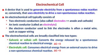
▪ Adevice that is used to generate electricity from a spontaneous redox reaction
or, conversely, that uses electricity to drive a non-spontaneous redox reaction.
▪ An electrochemical cell typically consists of
• Two electronic conductors (also called electrodes >> anode and cathode)
• An ionic conductor (called an electrolyte)
• the electron conductor used to link the electrodes is often a metal wire,
such as copper wiring
▪ The electrochemical cells are broadly classified into two types:
• Galvanic or voltaic cell: Converts the energy released by a spontaneous
chemical reaction to electrical energy.
• Electrolytic cell: Consumes electrical energy from an external source to drive
a non-spontaneous chemical reaction. ΔG > 0
ΔG < 0
4.
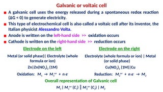
Galvanic or voltaiccell
▪ A galvanic cell uses the energy released during a spontaneous redox reaction
(ΔG < 0) to generate electricity.
▪ This type of electrochemical cell is also called a voltaic cell after its inventor, the
Italian physicist Alessandro Volta.
▪ Anode is written on the left-hand side >> oxidation occurs
▪ Cathode is written on the right-hand side >> reduction occurs
Electrode on the left Electrode on the right
Metal (or solid phase)| Electrolyte (whole
formula or ion)
Zn|Zn(NO3)2 (1M)
Oxidation: M1 → M1
n+
+ n e-
Electrolyte (whole formula or ion) | Metal
(or solid phase)
Cu(NO3)2 (1M)|Cu
Reduction: M2
n+
+ n e-
→ M2
Overall representation of Galvanic cell
M1 | M1
n+
(C1) ║ M2
n+
(C2) | M2
5.
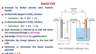
Daniel Cell
▪ Inventedby British chemist John Frederic
Daniell.
▪ Zn Electrode dipped in ZnSO4 solution:
• Oxidation: Zn → Zn2+
+ 2 e-
▪ Cu Electrode dipped in CuSO4 solution:
• Reduction: Cu2+
+ 2 e-
→ Cu
▪ Each electrode is referred to as half cell which
are connected through a salt bridge
▪ Salt bridge: KCl or NH4Cl in a gelatine form
▪ Maintains the charge balance in the two half
cells
▪ Minimizes or eliminates the liquid junction
potential
6.
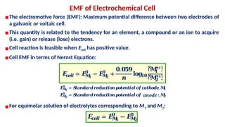
▪The electromotive force(EMF): Maximum potential difference between two electrodes of
a galvanic or voltaic cell.
▪This quantity is related to the tendency for an element, a compound or an ion to acquire
(i.e. gain) or release (lose) electrons.
▪Cell reaction is feasible when Ecell has positive value.
▪Cell EMF in terms of Nernst Equation:
EMF of Electrochemical Cell
▪For equimolar solution of electrolytes corresponding to M1 and M2:
𝑬
𝒄
𝒆𝒍𝒍 = 𝑬
𝑴
𝟏
𝟎
− 𝑬
𝑴
𝟐
𝟎
+
𝟎.𝟎𝟓𝟗
𝒏
𝐥𝐨𝐠
𝟏𝟎
ሾ
𝑴
𝟏
𝒏+ሿ
ሾ
𝑴
𝟐
𝒏+ሿ
𝑬
𝑴
𝟏
𝟎
= 𝑺
𝒕𝒂𝒏𝒅𝒂𝒓𝒅𝒓𝒆𝒅𝒖𝒄
𝒕𝒊𝒐𝒏𝒑
𝒐𝒕𝒆𝒏𝒕𝒊𝒂𝒍𝒐𝒇𝒄
𝒂𝒕𝒉𝒐𝒅𝒆,𝑴
𝟏
𝑬
𝑴
𝟐
𝟎
= 𝑺
𝒕𝒂𝒏𝒅𝒂𝒓𝒅𝒓𝒆𝒅𝒖𝒄
𝒕𝒊𝒐𝒏𝒑
𝒐𝒕𝒆𝒏𝒕𝒊𝒂𝒍𝒐𝒇𝒄
𝒂𝒕𝒉𝒐𝒅𝒆,𝑴
𝟐
anode
𝑬
𝒄
𝒆𝒍𝒍 = 𝑬
𝑴
𝟏
𝟎
− 𝑬
𝑴
𝟐
𝟎
7.
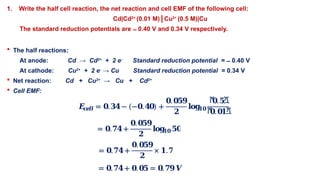
1. Write thehalf cell reaction, the net reaction and cell EMF of the following cell:
Cd|Cd2+
(0.01 M)║Cu2+
(0.5 M)|Cu
The standard reduction potentials are 0.40 V and 0.34 V respectively.
̶
The half reactions:
At anode: Cd → Cd2+
+ 2 e-
Standard reduction potential = 0.40 V
̶
At cathode: Cu2+
+ 2 e-
→ Cu Standard reduction potential = 0.34 V
Net reaction: Cd + Cu2+
→ Cu + Cd2+
Cell EMF:
𝑬
𝒄
𝒆𝒍𝒍 = 𝟎.𝟑𝟒− (−𝟎.𝟒𝟎) +
𝟎.𝟎𝟓𝟗
𝟐
𝐥𝐨𝐠
𝟏𝟎
ሾ
𝟎.𝟓ሿ
ሾ
𝟎.𝟎𝟏ሿ
= 𝟎.𝟕𝟒+
𝟎.𝟎𝟓𝟗
𝟐
𝐥𝐨𝐠
𝟏𝟎𝟓𝟎
= 𝟎.𝟕𝟒+
𝟎.𝟎𝟓𝟗
𝟐
× 𝟏.𝟕
= 𝟎.𝟕𝟒+ 𝟎.𝟎𝟓 = 𝟎.𝟕𝟗𝑽
8.
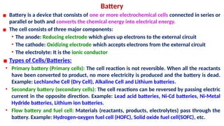
Battery
▪ Battery isa device that consists of one or more electrochemical cells connected in series or
parallel or both and converts the chemical energy into electrical energy.
▪ The cell consists of three major components:
• The anode: Reducing electrode which gives up electrons to the external circuit
• The cathode: Oxidizing electrode which accepts electrons from the external circuit
• The electrolyte: It is the ionic conductor
▪ Types of Cells/Batteries:
• Primary battery (Primary cells): The cell reaction is not reversible. When all the reactants
have been converted to product, no more electricity is produced and the battery is dead.
Example: Lechlanche Cell (Dry Cell), Alkaline Cell and Lithium batteries.
• Secondary battery (secondary cells): The cell reactions can be reversed by passing electric
current in the opposite direction. Example: Lead acid batteries, Ni-Cd batteries, Ni-Metal
Hydride batteries, Lithium ion batteries.
• Flow battery and fuel cell: Materials (reactants, products, electrolytes) pass through the
battery. Example: Hydrogen-oxygen fuel cell (HOFC), Solid oxide fuel cell(SOFC), etc.
9.
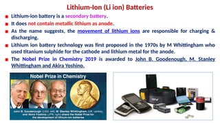
Lithium-Ion (Li ion)Batteries
▪ Lithium-ion battery is a secondary battery.
▪ It does not contain metallic lithium as anode.
▪ As the name suggests, the movement of lithium ions are responsible for charging &
discharging.
▪ Lithium ion battery technology was first proposed in the 1970s by M Whittingham who
used titanium sulphide for the cathode and lithium metal for the anode.
▪ The Nobel Prize in Chemistry 2019 is awarded to John B. Goodenough, M. Stanley
Whittingham and Akira Yoshino.
10.
Why lithium?
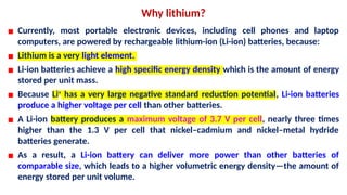
▪ Currently,most portable electronic devices, including cell phones and laptop
computers, are powered by rechargeable lithium-ion (Li-ion) batteries, because:
▪ Lithium is a very light element.
▪ Li-ion batteries achieve a high specific energy density which is the amount of energy
stored per unit mass.
▪ Because Li+
has a very large negative standard reduction potential, Li-ion batteries
produce a higher voltage per cell than other batteries.
▪ A Li-ion battery produces a maximum voltage of 3.7 V per cell, nearly three times
higher than the 1.3 V per cell that nickel–cadmium and nickel–metal hydride
batteries generate.
▪ As a result, a Li-ion battery can deliver more power than other batteries of
comparable size, which leads to a higher volumetric energy density—the amount of
energy stored per unit volume.
11.
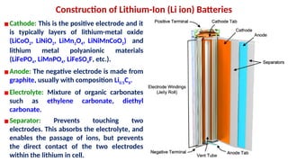
Construction of Lithium-Ion(Li ion) Batteries
▪Cathode: This is the positive electrode and it
is typically layers of lithium-metal oxide
(LiCoO2, LiNiO2, LiMn2O4, LiNiMnCoO2) and
lithium metal polyanionic materials
(LiFePO4, LiMnPO4, LiFeSO4F, etc.).
▪Anode: The negative electrode is made from
graphite, usually with composition Li0.5C6.
▪Electrolyte: Mixture of organic carbonates
such as ethylene carbonate, diethyl
carbonate.
▪Separator: Prevents touching two
electrodes. This absorbs the electrolyte, and
enables the passage of ions, but prevents
the direct contact of the two electrodes
within the lithium in cell.
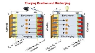
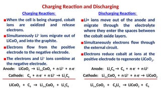
Charging Reaction andDischarging
Charging Reaction:
▪When the cell is being charged, cobalt
ions are oxidized and release
electrons.
▪Simultaneously Li+
ions migrate out of
LiCoO2 and into the graphite.
▪Electrons flow from the positive
electrode to the negative electrode.
▪The electrons and Li+
ions combine at
the negative electrode.
Discharging Reaction:
▪Li+ ions move out of the anode and
migrate through the electrolyte
where they enter the spaces between
the cobalt oxide layers.
▪Simultaneously electrons flow through
the external circuit.
▪Electrons reduce cobalt at ions at the
positive electrode to regenerate LiCoO2.
Anode: LiCoO2 → Li1-nCoO2 + n Li+
+ n e-
Cathode: C6 + n e-
+ n Li+
→ LinC6
LiCoO2 + C6 → Li1-nCoO2 + LinC6
Anode: LinC6 → C6 + n e-
+ n Li+
Cathode: Li1-nCoO2 + n Li+
+ n e-
→ LiCoO2
Li1-nCoO2 + C6Lin → LiCoO2 + C6
14.
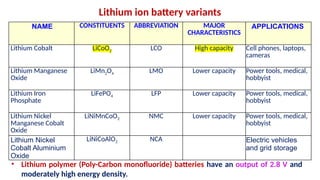
Lithium ion batteryvariants
NAME CONSTITUENTS ABBREVIATION MAJOR
CHARACTERISTICS
APPLICATIONS
Lithium Cobalt LiCoO2 LCO High capacity Cell phones, laptops,
cameras
Lithium Manganese
Oxide
LiMn2O4 LMO Lower capacity Power tools, medical,
hobbyist
Lithium Iron
Phosphate
LiFePO4 LFP Lower capacity Power tools, medical,
hobbyist
Lithium Nickel
Manganese Cobalt
Oxide
LiNiMnCoO2 NMC Lower capacity Power tools, medical,
hobbyist
Lithium Nickel
Cobalt Aluminium
Oxide
LiNiCoAlO2 NCA Electric vehicles
and grid storage
• Lithium polymer (Poly-Carbon monofluoride) batteries have an output of 2.8 V and
moderately high energy density.
15.
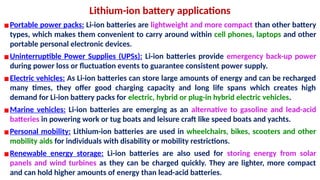
Lithium-ion battery applications
▪Portablepower packs: Li-ion batteries are lightweight and more compact than other battery
types, which makes them convenient to carry around within cell phones, laptops and other
portable personal electronic devices.
▪Uninterruptible Power Supplies (UPSs): Li-ion batteries provide emergency back-up power
during power loss or fluctuation events to guarantee consistent power supply.
▪Electric vehicles: As Li-ion batteries can store large amounts of energy and can be recharged
many times, they offer good charging capacity and long life spans which creates high
demand for Li-ion battery packs for electric, hybrid or plug-in hybrid electric vehicles.
▪Marine vehicles: Li-ion batteries are emerging as an alternative to gasoline and lead-acid
batteries in powering work or tug boats and leisure craft like speed boats and yachts.
▪Personal mobility: Lithium-ion batteries are used in wheelchairs, bikes, scooters and other
mobility aids for individuals with disability or mobility restrictions.
▪Renewable energy storage: Li-ion batteries are also used for storing energy from solar
panels and wind turbines as they can be charged quickly. They are lighter, more compact
and can hold higher amounts of energy than lead-acid batteries.
16.
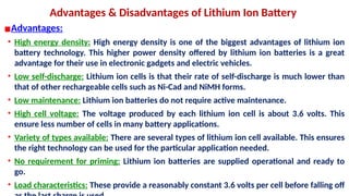
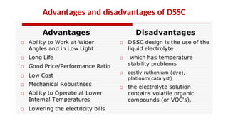
Advantages & Disadvantagesof Lithium Ion Battery
▪Advantages:
• High energy density: High energy density is one of the biggest advantages of lithium ion
battery technology. This higher power density offered by lithium ion batteries is a great
advantage for their use in electronic gadgets and electric vehicles.
• Low self-discharge: Lithium ion cells is that their rate of self-discharge is much lower than
that of other rechargeable cells such as Ni-Cad and NiMH forms.
• Low maintenance: Lithium ion batteries do not require active maintenance.
• High cell voltage: The voltage produced by each lithium ion cell is about 3.6 volts. This
ensure less number of cells in many battery applications.
• Variety of types available: There are several types of lithium ion cell available. This ensures
the right technology can be used for the particular application needed.
• No requirement for priming: Lithium ion batteries are supplied operational and ready to
go.
• Load characteristics: These provide a reasonably constant 3.6 volts per cell before falling off
17.
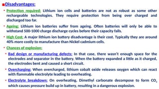
▪Disadvantages:
• Protection required:Lithium ion cells and batteries are not as robust as some other
rechargeable technologies. They require protection from being over charged and
discharged too far.
• Ageing: Lithium ion batteries suffer from ageing. Often batteries will only be able to
withstand 500-1000 charge discharge cycles before their capacity falls.
• High Cost: A major lithium ion battery disadvantage is their cost. Typically they are around
40% more costly to manufacture than Nickel cadmium cells.
• Chances of explosion:
• Bad design or manufacturing defects: In that case, there wasn’t enough space for the
electrodes and separator in the battery. When the battery expanded a little as it charged,
the electrodes bent and caused a short circuit.
• Overcharging: When overcharged, lithium cobalt oxide releases oxygen which can react
with flammable electrolyte leading to overheating.
• Electrolyte breakdown: On overheating, Dimethyl carbonate decompose to form CO2
which causes pressure build up in battery, resulting in a dangerous explosion.
18.
Fuel Cells
▪ Afuel cell is a device that converts chemical potential energy (energy stored in molecular
bonds) into electrical energy
▪ Electricity is generated without combustion by combining hydrogen and oxygen to
produce water and heat
▪ They offer higher electrical efficiency (≥ 40%) compared to conventional power
generation systems.
19.
Types of FuelCells
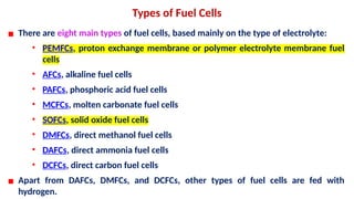
▪ There are eight main types of fuel cells, based mainly on the type of electrolyte:
• PEMFCs, proton exchange membrane or polymer electrolyte membrane fuel
cells
• AFCs, alkaline fuel cells
• PAFCs, phosphoric acid fuel cells
• MCFCs, molten carbonate fuel cells
• SOFCs, solid oxide fuel cells
• DMFCs, direct methanol fuel cells
• DAFCs, direct ammonia fuel cells
• DCFCs, direct carbon fuel cells
▪ Apart from DAFCs, DMFCs, and DCFCs, other types of fuel cells are fed with
hydrogen.
20.
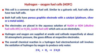
Hydrogen – oxygenfuel cells (HOFC)
▪ This cell is a common type of fuel cell. Similar to a galvanic cell, fuel cells also
have two half cells.
▪ Both half cells have porous graphite electrode with a catalyst (platinum, silver
or a metal oxide).
▪ The electrodes are placed in the aqueous solution of NaOH or KOH (alkaline
fuel cells-AFC) or H2SO4 (acidic fuel cell) which acts as an electrolyte.
▪ Hydrogen and oxygen are supplied at anode and cathode respectively at about
50 atmospheric pressure, the gases diffuse at respective electrodes.
▪ The overall chemical reaction in a hydrogen fuel electrochemical cell involves
the oxidation of hydrogen by oxygen to produce only water.
2 H2 + O2 → 2 H2O
22
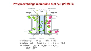
Proton exchange membranefuel cell (PEMFC)
This type of fuel cell utilize water-based, acidic polymer electrolyte
membranes (PEMs), such as Nafion, to conduct protons for ion exchange
purposes.
• Nafion membranes are composed mainly of a polytetrafluoroethylene (PTFE) backbone with side chains
containing ether groups and a sulfonic acid unit at its end.
PEMFC cells operate at relatively low temperatures (< 80°C).
Due to the relatively low temperatures and the use of precious metal-based electrodes, these cells
must be operated on pure hydrogen.
23.
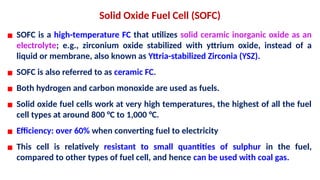
Solid Oxide FuelCell (SOFC)
▪ SOFC is a high-temperature FC that utilizes solid ceramic inorganic oxide as an
electrolyte; e.g., zirconium oxide stabilized with yttrium oxide, instead of a
liquid or membrane, also known as Yttria-stabilized Zirconia (YSZ).
▪ SOFC is also referred to as ceramic FC.
▪ Both hydrogen and carbon monoxide are used as fuels.
▪ Solid oxide fuel cells work at very high temperatures, the highest of all the fuel
cell types at around 800 °C to 1,000 °C.
▪ Efficiency: over 60% when converting fuel to electricity
▪ This cell is relatively resistant to small quantities of sulphur in the fuel,
compared to other types of fuel cell, and hence can be used with coal gas.
24.
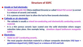
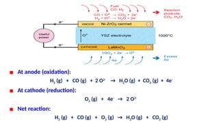
Structure of SOFC
▪Anode or fuel electrode:
• Nickel mixed with YSZ (Yttria stabilized Zirconia) or called Nickel-YSZ cermet (a cermet
is a mixture of ceramic and metal).
• It is a porous ceramic layer to allow the fuel to flow towards electrolyte.
▪ Cathode or air electrode:
• The cathode is usually a mixed ion-conducting and electronically conducting ceramic
material.
• It is a thin porous ceramic layer coated over the solid electrolyte where oxygen
reduction takes place. One example being, strontium doped lanthanum manganite
(LSM).
▪ Electrolyte:
• Oxide ion (O2-
) conducting ceramic.
• The most popular electrolyte material is a bilayer composite electrolyte (YSZ layer +
gadolinium doped CeO2) (GDC) layer) or a mixture of ZrO and CaO.
25.
▪ At anode(oxidation):
H2 (g) + CO (g) + 2 O2-
→ H2O (g) + CO2 (g) + 4e-
▪ At cathode (reduction):
O2 (g) + 4e-
→ 2 O2-
▪ Net reaction:
H2 (g) + CO (g) + O2 (g) → H2O (g) + CO2 (g)
26.
▪ Advantages ofSOFC:
• SOFCs have a number of advantages due to their solid materials and high
operating temperature.
• Since all the components are solid, as a result, there is no need for electrolyte
loss maintenance and electrode corrosion is eliminated.
• Also because of high-temperature operation, the SOFC has a better ability to
tolerate the presence of impurities as a result of life increasing.
• High efficiencies: Due to high-quality waste heat for cogeneration
applications and low activation losses, the efficiency for electricity
production is great.
• Low emissions. Releasing negligible pollution. It is the cleanest among all fuel
cells.
27.
▪ Disadvantages:
• Highoperating temperature (500 to 1,000 °C) which results in longer start up
times and mechanical/chemical compatibility issues.
• The cost and complex fabrication are also significant problems that need to be
solved.
• Applications:
• SOFCs are being considered for a wide range of applications, such as working
as power systems for trains, ships and vehicles; supplying electrical power for
residential or industrial utility.
• Stationary power generation
• By product gases are channeled to turbines to generate more electricity:
cogeneration of heat and power and improves overall efficiency.
• Auxiliary power units in vehicles
28.
Solar Energy Potential
▪Theoretical:1.2x10⁵
TW solar energy potential
(1.76 x10⁵
TW striking Earth; 0.30 Global mean albedo)
Energy in 1 hr of sunlight ↔ 14 TW for a year
▪Practical: ≈ 600 TW solar energy potential (50 TW - 1500 TW depending on land fraction
etc.; WEA 2000)
Onshore electricity generation potential of ≈ 60 TW (10% conversion efficiency)
Photosynthesis: 90 TW
29.
Types of solarenergy conversion cells
• Photovoltaic Cells
• Dye-sensitized solar cells
30.
Photovoltaic Cells
▪ Asolar cell is a device that converts the energy of sunlight directly into electricity
by the photovoltaic effect.
▪ The photovoltaic effect involves creation of a voltage (or a corresponding electric
current) in a material upon exposure to electro-magnetic radiation.
▪ Though the photovoltaic effect is directly related to the photoelectric effect, the
two processes are different.
▪ There are several different types of PV cells which all use semiconductors to
interact with incoming photons from the Sun in order to generate an electric
current.
▪ Highly purified silicon (Si) from sand, quartz, etc. is “doped” with intentional
impurities at controlled concentrations often used in Photovoltaic Cells.
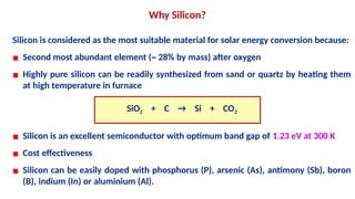
Silicon is consideredas the most suitable material for solar energy conversion because:
▪ Second most abundant element (~ 28% by mass) after oxygen
▪ Highly pure silicon can be readily synthesized from sand or quartz by heating them
at high temperature in furnace
SiO2 + C → Si + CO2
▪ Silicon is an excellent semiconductor with optimum band gap of 1.23 eV at 300 K
▪ Cost effectiveness
▪ Silicon can be easily doped with phosphorus (P), arsenic (As), antimony (Sb), boron
(B), indium (In) or aluminium (Al).
Why Silicon?
33.
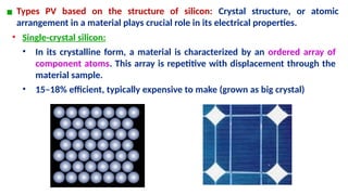
▪ Types PVbased on the structure of silicon: Crystal structure, or atomic
arrangement in a material plays crucial role in its electrical properties.
• Single-crystal silicon:
• In its crystalline form, a material is characterized by an ordered array of
component atoms. This array is repetitive with displacement through the
material sample.
• 15–18% efficient, typically expensive to make (grown as big crystal)
34.
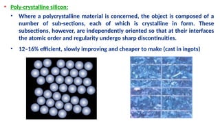
• Poly-crystalline silicon:
•Where a polycrystalline material is concerned, the object is composed of a
number of sub-sections, each of which is crystalline in form. These
subsections, however, are independently oriented so that at their interfaces
the atomic order and regularity undergo sharp discontinuities.
• 12–16% efficient, slowly improving and cheaper to make (cast in ingots)
35.
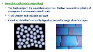
• Amorphous silicon(non-crystalline)
• The final category, the amorphous material, displays no atomic regularity of
arrangement on any macroscopic scale.
• 4–8% Efficient and cheapest per Watt
• Called as “thin film” and easily deposited on a wide range of surface types
36.
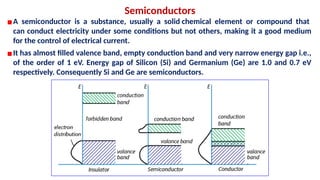
Semiconductors
▪A semiconductor isa substance, usually a solid chemical element or compound that
can conduct electricity under some conditions but not others, making it a good medium
for the control of electrical current.
▪It has almost filled valence band, empty conduction band and very narrow energy gap i.e.,
of the order of 1 eV. Energy gap of Silicon (Si) and Germanium (Ge) are 1.0 and 0.7 eV
respectively. Consequently Si and Ge are semiconductors.
37.
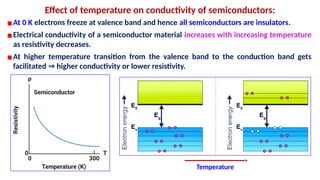
Effect of temperatureon conductivity of semiconductors:
▪At 0 K electrons freeze at valence band and hence all semiconductors are insulators.
▪Electrical conductivity of a semiconductor material increases with increasing temperature
as resistivity decreases.
▪At higher temperature transition from the valence band to the conduction band gets
facilitated higher conductivity or lower resistivity.
⇒
Temperature
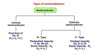
Intrinsic Semiconductor
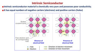
▪Intrinsic semiconductormaterial is chemically very pure and possesses poor conductivity.
▪It has equal numbers of negative carriers (electrons) and positive carriers (holes)
Absence of
electrical field
Presence of
electrical field
40.
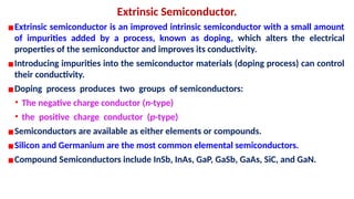
Extrinsic Semiconductor.
▪Extrinsic semiconductoris an improved intrinsic semiconductor with a small amount
of impurities added by a process, known as doping, which alters the electrical
properties of the semiconductor and improves its conductivity.
▪Introducing impurities into the semiconductor materials (doping process) can control
their conductivity.
▪Doping process produces two groups of semiconductors:
• The negative charge conductor (n-type)
• the positive charge conductor (p-type)
▪Semiconductors are available as either elements or compounds.
▪Silicon and Germanium are the most common elemental semiconductors.
▪Compound Semiconductors include InSb, InAs, GaP, GaSb, GaAs, SiC, and GaN.
41.
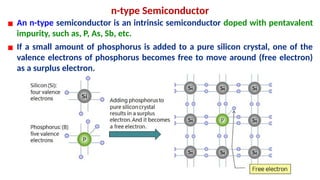
n-type Semiconductor
▪ Ann-type semiconductor is an intrinsic semiconductor doped with pentavalent
impurity, such as, P, As, Sb, etc.
▪ If a small amount of phosphorus is added to a pure silicon crystal, one of the
valence electrons of phosphorus becomes free to move around (free electron)
as a surplus electron.
42.
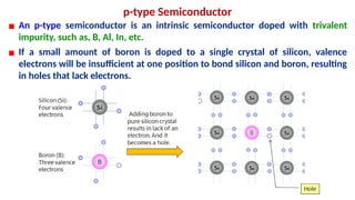
p-type Semiconductor
▪ Anp-type semiconductor is an intrinsic semiconductor doped with trivalent
impurity, such as, B, Al, In, etc.
▪ If a small amount of boron is doped to a single crystal of silicon, valence
electrons will be insufficient at one position to bond silicon and boron, resulting
in holes that lack electrons.
43.
Preparation of Semiconductors:~ 99.9999% pure Si and Ge
▪Distillation:
• Separation of materials is based on the difference in boiling points.
• For Ge GeCl
⇒ 4 and for Si SiHCl
⇒ 3
• As is removed from GeCl4 (b.p. 83.1 0 C) with the help of HCl.
• Pure GeCl4 is obtained by fractional distillation in presence of chlorine.
• After cooling, the pure GeCl4 is treated with extra pure water to get germanium
oxide.
• Subsequent reduction of GeCl4 with pure hydrogen affords highly pure elemental Ge.
GeCl4 + 2 H2O → GeO2 + 4 HCl
GeO2 + 2 H2 → Ge + 2 H2O
44.
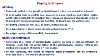
Doping techniques
▪Epitaxy:
• Involvesin unified crystal growth or deposition of a thin crystal on another substrate.
• Si or Ge wafer (kept in graphite boat) is placed in a long cylindrical quartz tube reactor,
which is then heated (by RF induction coil). Then gases containing compounds of Ge or
Si mixed with calculated/appropriate quantities of dopant over the wafer results.
• For getting Si epitaxial film, SiCl4, H2 and N2 mixture is used.
• For n-type doping above mixture is used with phosphine (PH
⇒ 3)
• For p-type doping Diborane (B
⇒ 2H6) is employed.
▪Diffusion technique:
• Conversion of a region of semiconductor material by solid or gaseous diffusion of
impurity atom into the crystal lattice of the semiconductor material without any
melting and it consists of heating a P-type dopant.
• By this technique, the extent of impurity atoms penetration can be controlled
even less than a few millions of a centimetre.
45.
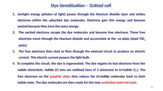
1. Sunlight energy(photon of light) passes through the titanium dioxide layer and strikes
electrons within the adsorbed dye molecules. Electrons gain this energy and become
excited because they have the extra energy.
2. The excited electrons escape the dye molecules and become free electrons. These free
electrons move through the titanium dioxide and accumulate at the -ve plate (dyed TiO2
plate).
3. The free electrons then start to flow through the external circuit to produce an electric
current. This electric current powers the light bulb.
4. To complete the circuit, the dye is regenerated. The dye regains its lost electrons from the
iodide electrolyte. Iodide (I-
) ions are oxidised (loss of 2 electrons) to tri-iodide (I3
-
). The
free electrons on the graphite plate then reduce the tri-iodide molecules back to their
iodide state. The dye molecules are then ready for the next excitation/oxid/red cycle.
Dye Sensitization - Grätzel cell
45
▪ Transparent andConductive Substrate
• Substrate for the deposition of the semiconductor and catalyst, acting also as
current collectors
• Characteristics of a substrate:
More than 80% of transparency
Should have a high electrical conductivity.
• The fluorine-doped tin oxide (FTO, SnO2: F) and indium-doped tin oxide (ITO,
In2O3: Sn) are usually applied as a conductive substrate in DSSCs.
• These substrates consist of soda lime glass coated with the layers of ITO and
FTO.
• The ITO films have a transmittance > 80% and 18 Ω /cm2
of sheet resistance,
• FTO films show a lower transmittance of ~ 75% in the visible region and sheet
resistance of 8.5 Ω /cm2
48.
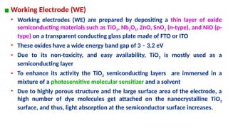
▪ Working Electrode(WE)
• Working electrodes (WE) are prepared by depositing a thin layer of oxide
semiconducting materials such as TiO2, Nb2O5, ZnO, SnO2 (n-type), and NiO (p-
type) on a transparent conducting glass plate made of FTO or ITO
• These oxides have a wide energy band gap of 3 – 3.2 eV
• Due to its non-toxicity, and easy availability, TiO2 is mostly used as a
semiconducting layer
• To enhance its activity the TiO2 semiconducting layers are immersed in a
mixture of a photosensitive molecular sensitizer and a solvent
• Due to highly porous structure and the large surface area of the electrode, a
high number of dye molecules get attached on the nanocrystalline TiO2
surface, and thus, light absorption at the semiconductor surface increases.
49.
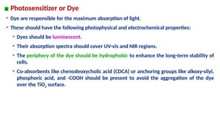
▪ Photosensitizer orDye
• Dye are responsible for the maximum absorption of light.
• These should have the following photophysical and electrochemical properties:
• Dyes should be luminescent.
• Their absorption spectra should cover UV-vis and NIR regions.
• The periphery of the dye should be hydrophobic to enhance the long-term stability of
cells.
• Co-absorbents like chenodeoxycholic acid (CDCA) or anchoring groups like alkoxy-silyl,
phosphoric acid, and -COOH should be present to avoid the aggregation of the dye
over the TiO2 surface.
50.
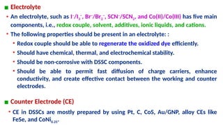
▪ Electrolyte
• Anelectrolyte, such as I−
/I3
−
, Br−
/Br2
−
, SCN−
/SCN2, and Co(II)/Co(III) has five main
components, i.e., redox couple, solvent, additives, ionic liquids, and cations.
• The following properties should be present in an electrolyte: :
• Redox couple should be able to regenerate the oxidized dye efficiently.
• Should have chemical, thermal, and electrochemical stability.
• Should be non-corrosive with DSSC components.
• Should be able to permit fast diffusion of charge carriers, enhance
conductivity, and create effective contact between the working and counter
electrodes.
▪ Counter Electrode (CE)
• CE in DSSCs are mostly prepared by using Pt, C, CoS, Au/GNP, alloy CEs like
FeSe, and CoNi0.25.
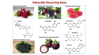
Construction of aGrätzel cell
o In Grätzel cell a range of organic dyes are used.
o Examples: Ruthenium-Polypyridine, Indoline dye & metal free organic dye.
o These dyes are extractable from simple foods such as hibiscus tea, tinned summer fruits,
blackberries.
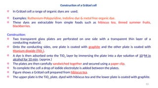
Construction:
o Two transparent glass plates are perforated on one side with a transparent thin layer of a
conducting material.
o Onto the conducting sides, one plate is coated with graphite and the other plate is coated with
titanium dioxide (TiO2).
o A dye is then adsorbed onto the TiO2 layer by immersing the plate into a dye solution of 10-4
M in
alcohol for 10 min. (approx.)
o The plates are then carefully sandwiched together and secured using a paper clip.
o To complete the cell a drop of iodide electrolyte is added between the plates.
o Figure shows a Grätzel cell prepared from hibiscus tea.
o The upper plate is the TiO2 plate, dyed with hibiscus tea and the lower plate is coated with graphite.
53
54.
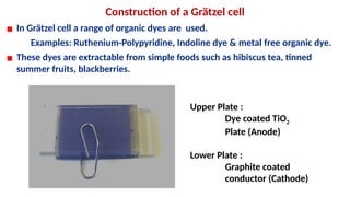
Construction of aGrätzel cell
▪ In Grätzel cell a range of organic dyes are used.
Examples: Ruthenium-Polypyridine, Indoline dye & metal free organic dye.
▪ These dyes are extractable from simple foods such as hibiscus tea, tinned
summer fruits, blackberries.
Upper Plate :
Dye coated TiO2
Plate (Anode)
Lower Plate :
Graphite coated
conductor (Cathode)
55.
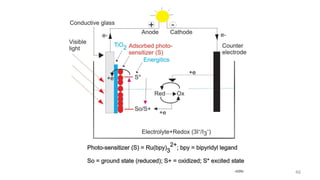
The working principleof DSSC involves four basic steps: light absorption, electron injection,
transportation of carrier, and collection of current.
Working Principle
▪ Sunlight energy (photon of light) passes through the titanium dioxide layer and absorbed
by the photosensitizer
▪ Due to the photon absorption, electrons get promoted from the ground state (Dye) to
the excited state (Dye*) of the dye
▪ Excited electrons with a lifetime of nanosecond range are injected into the conduction
band of nano-porous TiO2 electrode which lies below the excited state of the dye.
▪ As a result, the dye gets oxidized.
Dyeo + hν → Dye*
Dye* → Dye*+
+ e-
(TiO2)


![BATTERY CHEMISTRY [Autosaved].pptx](https://cdn.slidesharecdn.com/ss_thumbnails/batterychemistryautosaved-230306095147-71e692f9-thumbnail.jpg?width=640&height=640&fit=bounds)


