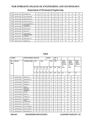
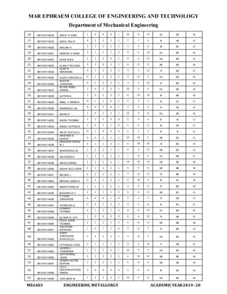
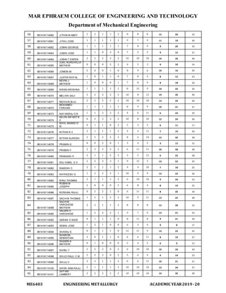
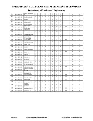
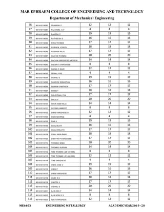
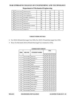
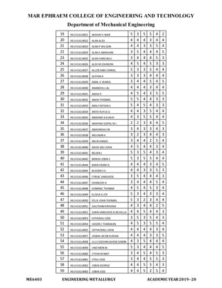
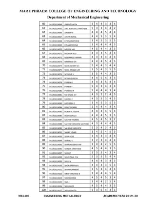
This document outlines the course content, outcomes, syllabus, assessment, and student list for the Engineering Metallurgy course at Mar Ephraem College of Engineering and Technology. The course is divided into 5 units covering alloy and phase diagrams, heat treatment, ferrous and non-ferrous metals, non-metallic materials, and mechanical properties testing. Assessment includes two continuous exams, assignments, a model exam, and an end of semester exam. The course aims to explain key metallurgical concepts and their applications in engineering. A list of 121 students enrolled in the course is also provided.
![MAR EPHRAEM COLLEGE OF ENGINEERING AND TECHNOLOGY
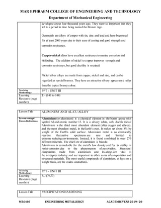
Department of Mechanical Engineering
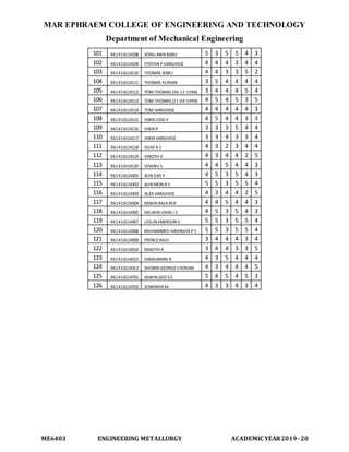
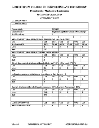
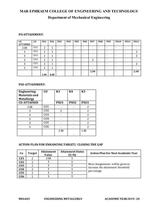
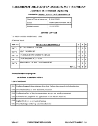
ME6403 ENGINEERING METALLURGY ACADEMIC YEAR2019-20
of steel with
Carbon. The depth of case obtained in components depends on the
time temperature, and type of carburizer used in the process.
There are three methods of carburizing namely
1) Pack or solid carburizing
2) Liquid carburizing (Liquid carburizing uses a molten potassium
cyanide salt
bath at a temp of 8500C and immersed in that bath)
3) Gas carburizing.
Pack carburizing or Solid carburizing
In this process components to be case hardened are packed
into a steel box along with carburizing and energizing mixture. The
mixture consists of a solid carburizer normally charcoal of 40 to
70%,barium carbonate of 20-25%, sodium carbonate of 3 to 12% (to
intensify the process) and CaCo3 of 3 to 5% (to prevent the carburizer
particles from caking). The box is covered and the lid is tightly sealed
with fire clay (to prevent the entry or escape of gases).
The box is then placed in a furnace and heated to a
temperature of 900 to 9800C for 6 to 72 hours. [The time depends on
case depth and temperature]. During heating the charcoal releases Co
gas which reacts with the metal and releases the desired carbon which
is absorbed in the austenite of the metal surface.
Gas carburizing
The parts to be gas carburized are kept in a tightly sealed
furnace chamber filled with a carburizing gas. Usually, the
carburizing gas is made to flow through the chambers at a given
speed. Any one of the saturated hydro carbons like methane (CH4),
ethane (C6H6),propane (C3H8) butane (C4H10) can be used for this
process. But Natural (having 96% CH4) is more commonly used. A
liquid hydrocarbon (Kerosene, benzene etc) is supplied drop wise into
the air tight furnace to activate the process.
Liquid carburizing
The process is suitable for case hardening small components. In this
both carbon and nitrogen are added to the steel surface. This is quite
similar to cyaniding. [except that the steel surface is higher in carbon](https://image.slidesharecdn.com/emmcoursefileupdated-220902045306-0caa10ec/85/EMM-COURSE-FILE-UPDATED-docx-29-320.jpg)
![MAR EPHRAEM COLLEGE OF ENGINEERING AND TECHNOLOGY
Department of Mechanical Engineering
ME6403 ENGINEERING METALLURGY ACADEMIC YEAR2019-20
and lower in nitrogen ].
In this process steel parts are immersed for I to 2 hours in a molten
cyanide salt bath [20 to 50% sodium cyanide, 30 to 40% sodium
carbonate and 18 to 30% sodium chloride ] kept at a temperature of
900o to 950oC. Now both carbon and nitrogen are added to the surface
of steel; producing a harder case than by gas carburizing. Case depth
obtained in liquid carburizing is very small, i.e., from 0.08 to 1.0 mm.
Nitriding
Nitriding is the process of diffusion saturation of certain alloy
steel surface with nitrogen. Alloying elements in steels like Al, Cr, V
and Mo would form very hard nitrides when they combine with
nitrogen. This is the basic principal of nitriding.
Nitriding is done at 5000-6000C. The parts to be nitrided are placed in
a tightly closed box which is installed in a heating furnace. Gaseous
ammonia is supplied to the box at a definite flow rate. Now atomic
nitrogen is formed due to the dissociation of NH3 by the reaction
NH3 = 3H + N
The Nitrogen gets diffused in the metal and forms very hard nitrides.
Nitriding is employed to increase the hardness, wear resistance,
endurance limit and corrosion resistance of steels. The process is
suitable for link pins, shafts, pump components, etc.
Cyaniding
It is also called as liquid carbonitriding. Cyaniding is a process of
diffusion saturation of steel with carbon and nitrogen at the same
time. In this process the parts to be case hardened are immersed in a
bath of molten cyanide bath. [The bath contains 20 – 25% NaCN, 25-
50%Nacl, and 25-50%Na2Co3] which is at a temperature slightly
above AC1 range.
The time of holding depends on the depth of case. Similar to
liquid carburzing carbon and nitrogen are absorbed into the steel
surface. [Less carbon and more Nitrogen]. Cyanided layers have a
higher wear resistance, higher hardness and higher corrosion
resistance as compared to carburized layers. It also increases fatigue
strength. Case depth is upto 0.3mm
Cyanides are poisonous therefore the process should be
carried out in special rooms and with strict observance of safety rules.](https://image.slidesharecdn.com/emmcoursefileupdated-220902045306-0caa10ec/85/EMM-COURSE-FILE-UPDATED-docx-30-320.jpg)
![MAR EPHRAEM COLLEGE OF ENGINEERING AND TECHNOLOGY
Department of Mechanical Engineering
ME6403 ENGINEERING METALLURGY ACADEMIC YEAR2019-20
austenite grain size.
Cobalt (Co) – improves strength at high temperatures and magnetic
permeability.
Zirconium (Zr) – increases strength and limits grain sizes.
Boron (B) – highly effective hardenability agent, improves
deformability and machinability.
Copper (Cu) – improves corrosion resistance.
Aluminum (Al) – deoxidizer, limits austenite grains growth
Teaching
Methodology:
PPT - UNIT III-FERROUS AND NON FERROUS
Learning
Resource (page
number)
T2- (235to 237)
Lesson Title STAINLESS AND TOOL STEELS
Lesson concept/
Points/Definitions
Stainless and Tool Steels
In metallurgy, stainless steel, also known as inox
steel or inox from French "inoxydable", is defined as a steel alloy with
a minimum of 10.5%[1] to 11% chromium content by mass.
Stainless steel does not readily corrode, rust or stain with
water as ordinary steel does, but despite the name it is not fully stain-
proof, most notably under low oxygen, high salinity, or poor
circulation environments.[3] It is also called corrosion-resistant
steel or CRESwhen the alloy type and grade are not detailed,
particularly in the aviation industry. There are different grades and
surface finishes of stainless steel to suit the environment the alloy
must endure. Stainless steel is used where both the properties of steel
and resistance to corrosion are required.
Stainless steel differs from carbon steel by the amount
of chromium present. Unprotected carbon steel rusts readily when
exposed to air and moisture. This iron oxide film (the rust) is active
and accelerates corrosion by forming more iron oxide, and due to the
dissimilar size of the iron and iron oxide molecules (iron oxide is
larger) these tend to flake and fall away. Stainless steels contain
sufficient chromium to form a passive film of chromium oxide, which
prevents further surface corrosion and blocks corrosion from
spreading into the metal's internal structure, and due to the similar size](https://image.slidesharecdn.com/emmcoursefileupdated-220902045306-0caa10ec/85/EMM-COURSE-FILE-UPDATED-docx-33-320.jpg)
![MAR EPHRAEM COLLEGE OF ENGINEERING AND TECHNOLOGY
Department of Mechanical Engineering
ME6403 ENGINEERING METALLURGY ACADEMIC YEAR2019-20
of the steel and oxide molecules they bond very strongly and remain
attached to the surface.[4]
Tool steel
Tool steel refers to a variety of carbon and alloy steels that
are particularly well-suited to be made into tools. Their suitability
comes from their distinctive hardness, resistance to abrasion, their
ability to hold a cutting edge, and/or their resistance to deformation at
elevated temperatures (red-hardness). Tool steel is generally used in
a heat-treated state. Many high carbon tool steels are also more
resistant to corrosion due to their higher ratios of elements such as
vanadium
With a carbon content between 0.7% and 1.5%, tool steels
are manufactured under carefully controlled conditions to produce the
required quality. The manganese content is often kept low to
minimize the possibility of cracking during water quenching.
However, proper heat treating of these steels is important for adequate
performance, and there are many suppliers who provide tooling
blanks intended for oil quenching.
Tool steels are made to a number of grades for different
applications. Choice of grade depends on, among other things,
whether a keen cutting edge is necessary, as in stamping dies, or
whether the tool has to withstand impact loading and service
conditions encountered with such hand tools as axes, pickaxes,
and quarrying implements. In general, the edge temperature under
expected use is an important determinant of both composition and
required heat treatment. The higher carbon grades are typically used
for such applications as stamping dies, metal cutting tools, etc.
Tool steels are also used for special applications
like injection molding because the resistance to abrasion is an
important criterion for a mold that will be used to produce hundreds
of thousands of parts.
Teaching
Methodology:
PPT - UNIT III-FERROUS AND NON FERROUS
Learning
Resource (page
number)
T2- (159 to 163)
Lesson Title HSLA - MARAGINGSTEELS
Lesson
concept/
HSLA - Maraging Steels](https://image.slidesharecdn.com/emmcoursefileupdated-220902045306-0caa10ec/85/EMM-COURSE-FILE-UPDATED-docx-34-320.jpg)
![MAR EPHRAEM COLLEGE OF ENGINEERING AND TECHNOLOGY
Department of Mechanical Engineering
ME6403 ENGINEERING METALLURGY ACADEMIC YEAR2019-20
Points/Definiti
ons
High-strength low-alloy steel (HSLA) is a type of alloy steel that
provides better mechanical properties or greater resistance to corrosion
than carbon steel. HSLA steels vary from other steels in that they are not made to
meet a specific chemical composition but rather to specific mechanical properties.
They have a carbon content between 0.05–0.25% to retain formability
and weldability. Other alloying elements include up to 2.0% manganese and small
quantities
of copper, nickel, niobium, nitrogen, vanadium, chromium,molybdenum, titanium,
calcium, rare earth elements, or zirconium.[1][2] Copper, titanium, vanadium, and
niobium are added for strengthening purposes.[2] These elements are intended to
alter the microstructure of carbon steels, which is usually a ferrite-
pearliteaggregate, to produce a very fine dispersion of alloy carbides in an almost
pure ferrite matrix. This eliminates the toughness-reducing effect of a pearlitic
volume fraction yet maintains and increases the material's strength by refining the
grain size, which in the case of ferrite increases yield strength by 50% for every
halving of the mean grain diameter. Precipitation strengthening plays a minor role,
too. Their yield strengths can be anywhere between 250–590 megapascals
(36,000–86,000 psi). Because of their higher strength and toughness HSLA steels
usually require 25 to 30% more power to form, as compared to carbon steels.[2]
Copper, silicon, nickel, chromium, and phosphorus are added to
increase corrosion resistance. Zirconium, calcium, and rare earth elements are
added for sulfide-inclusion shape control which increases formability. These are
needed because most HSLA steels have directionally sensitive properties.
Formability and impact strength can vary significantly when tested longitudinally
and transversely to the grain. Bends that are parallel to the longitudinal grain are
more likely to crack around the outer edge because it experiences tensile loads.
This directional characteristic is substantially reduced in HSLA steels that have
been treated for sulfide shape control.[2]
They are used in cars, trucks, cranes, bridges, roller coasters and
other structures that are designed to handle large amounts of stressor need a good
strength-to-weight ratio.[2] HSLA steels are usually 20 to 30% lighter than a
carbon steel with the same strength.[3][4]](https://image.slidesharecdn.com/emmcoursefileupdated-220902045306-0caa10ec/85/EMM-COURSE-FILE-UPDATED-docx-35-320.jpg)
![MAR EPHRAEM COLLEGE OF ENGINEERING AND TECHNOLOGY
Department of Mechanical Engineering
ME6403 ENGINEERING METALLURGY ACADEMIC YEAR2019-20
HSLA steels are also more resistant to rust than most carbon
steels because of their lack of pearlite – the fine layers of ferrite (almost pure iron)
and cementite in pearlite.[citation needed] HSLA steels usually have densities of around
7800 kg/m³.[5]
Maraging steels (a portmanteau of "martensitic" and "aging")
are steels (iron alloys) which are known for possessing superior strength and
toughness without losing malleability, although they cannot hold a good cutting
edge. Aging refers to the extended heat-treatment process. These steels are a
special class of low-carbon ultra-high-strength steels which derive their strength
not from carbon, but from precipitation of inter-metallic compounds. The principal
alloying element is 15 to 25 wt.% nickel.[1] Secondary alloying elements are added
to produce intermetallic precipitates, which include cobalt, molybdenum,
and titanium.[1] Original development was carried out on 20 and 25 wt.% Ni steels
to which small additions of Al, Ti, and Nb were made.
The common, non-stainless grades contain 17–19 wt.% nickel, 8–12 wt.% cobalt,
3–5 wt.% molybdenum, and 0.2–1.6 wt.% titanium. Addition of chromium
produces stainless grades resistant to corrosion. This also indirectly
increases hardenability as they require less nickel: high-chromium, high-nickel
steels are generally austenitic and unable to transform to martensite when heat
treated, while lower-nickel steels can transform to martensite. Alternative variants
of Ni-reduced maraging steels are based on alloys of Fe and Mn plus minor
additions of Al, Ni, and Ti where compositions between Fe-9wt.% Mn to Fe-
15wt.% Mn have been used. The Mn has a similar effect as Ni, i.e. it stabilizes the
austenite phase. Hence, depending on their Mn content, Fe-Mn maraging steels
can be fully martensitic after quenching them from the high temperature austenite
phase or they can contain retained austenite. The latter effect enables the design of
maraging-TRIP steels where TRIP stands for Transformation-Induced-Plasticity.[2]
Teaching
Methodology:
PPT - UNIT III-FERROUS AND NON FERROUS
Learning
Resource
(page
number)
T2- (303 to 304)
Lesson Title CAST IRONS - GREY, WHITE MALLEABLE, SPHEROIDAL](https://image.slidesharecdn.com/emmcoursefileupdated-220902045306-0caa10ec/85/EMM-COURSE-FILE-UPDATED-docx-36-320.jpg)
![MAR EPHRAEM COLLEGE OF ENGINEERING AND TECHNOLOGY
Department of Mechanical Engineering
ME6403 ENGINEERING METALLURGY ACADEMIC YEAR2019-20
Lesson concept/
Points/Definitions
Precipitation hardening, also called age hardening, is a heat
treatment technique used to increase the yield strength
of malleable materials, including most structural alloys of
aluminium, magnesium, nickel, titanium, and some stainless steels.
In superalloys, it is known to cause yield strength anomaly providing
excellent high temperature strength.
Precipitation hardening relies on changes in
solid solubility with temperature to produce fine particles of an
impurity phase, which impede the movement of dislocations, or defects in
a crystal's lattice. Since dislocations are often the dominant carriers
of plasticity, this serves to harden the material. The impurities play the same
role as the particle substances in particle-reinforced composite materials.
Just as the formation of ice in air can produce clouds, snow, or hail,
depending upon the thermal history of a given portion of the
atmosphere, precipitation in solids can produce many different sizes of
particles, which have radically different properties. Unlike
ordinary tempering, alloys must be kept at elevated temperature for hours to
allow precipitation to take place. This time delay is called aging.
Teaching
Methodology:
PPT - UNIT III
Learning
Resource (page
number)
R4-213;T2- (289)
Lesson Title BEARINGALLOYS.
Lesson concept/
Points/Definitions
Babbitt, also called Babbitt metal or bearing metal, is any of
severalalloys used for the bearing surface in a plain bearing.
The original Babbitt metal was invented in 1839 by Isaac
Babbitt[1] in Taunton, Massachusetts,USA.
Babbitt metal is most commonly used as a thin surface layer in a complex,
multi-metal structure, but its original use was as a cast-in-place bulk bearing
material. Babbitt metal is characterized by its resistance to galling. Babbitt
metal is soft and easily damaged, which suggests that it might be unsuitable
for a bearing surface. However, its structure is made up of small
hard crystals dispersed in a softer metal, which makes it a metal matrix
composite. As the bearing wears, the softer metal erodes somewhat, which
creates paths for lubricant between the hard high spots that provide the
actual bearing surface. When tin is used as the softer metal, friction causes
the tin to melt and function as a lubricant, which protects the bearing from
wear when other lubricants are absent.
Internal combustion engines use Babbitt metal which is primarily tin-based
because it can withstand cyclic loading. Lead-based Babbitt tends to work-
harden and develop cracks but it is suitable for constant-turning tools such as
sawblades.](https://image.slidesharecdn.com/emmcoursefileupdated-220902045306-0caa10ec/85/EMM-COURSE-FILE-UPDATED-docx-41-320.jpg)
![MAR EPHRAEM COLLEGE OF ENGINEERING AND TECHNOLOGY
Department of Mechanical Engineering
ME6403 ENGINEERING METALLURGY ACADEMIC YEAR2019-20
Teaching
Methodology:
PPT - UNIT III
Learning
Resource (page
number)
T2- (305-307);R4-218
Lesson Title POLYMERS
Lesson concept/
Points/Definitions
A polymer is a large molecule (macromolecule) composed of
repeating structural units. These subunits are typically connected by
covalent chemical bonds. Although the term polymer is sometimes
taken to refer to plastics, it actually encompasses a large class of
natural and synthetic materials with a wide variety of properties.
Because of the extraordinary range of properties of polymeric
materials,[2] they play an essential and ubiquitous role in everyday
life.[3] This role ranges from familiar synthetic plastics and elastomers
to natural biopolymers such as nucleic acids and proteins that are
essential for life.
Natural polymeric materials such as shellac, amber, and natural rubber have
been used for centuries. A variety of other natural polymers exist, such as
cellulose, which is the main constituent of wood and paper. The list of
synthetic polymers includes synthetic rubber, Bakelite, neoprene, nylon,
PVC, polystyrene, polyethylene, polypropylene, polyacrylonitrile, PVB,
silicone, and many more.
Most commonly, the continuously linked backbone of a polymer used
for the preparation of plastics consists mainly of carbon atoms. A
simple example is polyethylene, whose repeating unit is based on
ethylene monomer. However, other structures do exist; for example,
elements such as silicon form familiar materials such as silicones,
examples being silly putty and waterproof plumbing sealant. Oxygen
is also commonly present in polymer backbones, such as those of
polyethylene glycol, polysaccharides (in glycosidic bonds), and DNA
(in phosphodiester bonds).
Polymers are studied in the fields of polymer chemistry, polymer physics,
and polymer science
Teaching
Methodology:
PPT - UNIT IV
Learning
Resource (page
number)
T1- (183)
Lesson Title TYPES OF POLYMER
Lesson concept/
Points/Definitions
Polymer science is a broad field that includes many types of materials
which incorporate long chain structures with many repeated units. One](https://image.slidesharecdn.com/emmcoursefileupdated-220902045306-0caa10ec/85/EMM-COURSE-FILE-UPDATED-docx-42-320.jpg)