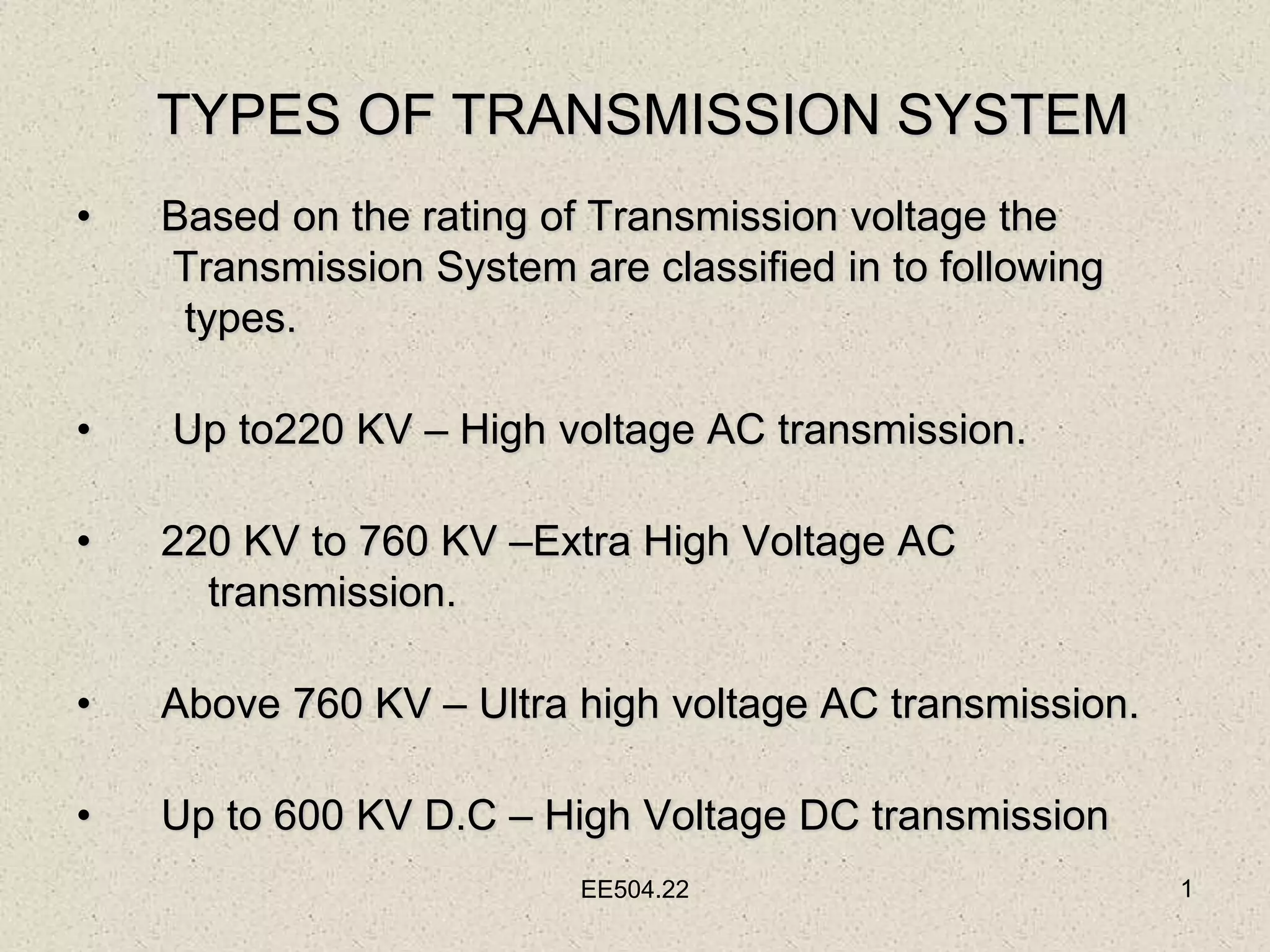
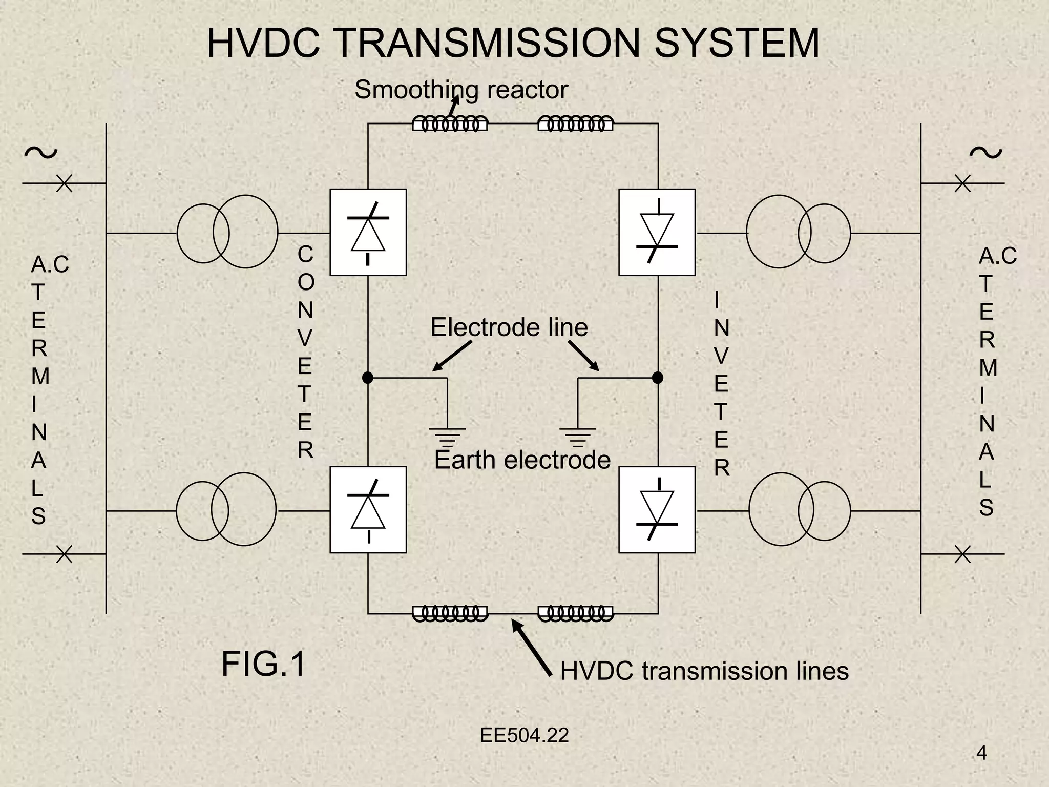
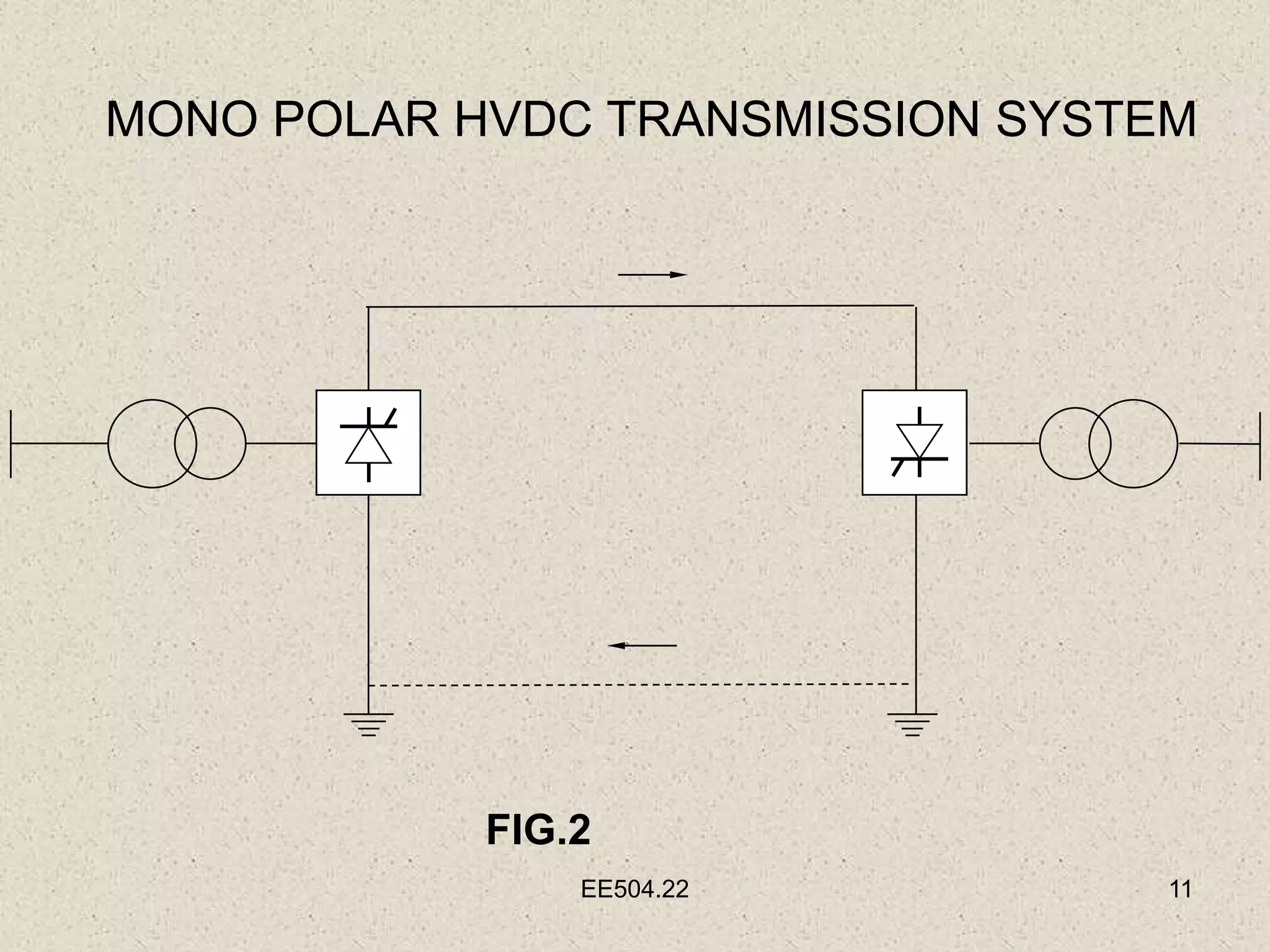
TYPES OF TRANSMISSION SYSTEM
• Based on the rating of Transmission voltage the
Transmission System are classified in to following
types.
• Up to220 KV – High voltage AC transmission.
• 220 KV to 760 KV –Extra High Voltage AC
transmission.
• Above 760 KV – Ultra high voltage AC transmission.
• Up to 600 KV D.C – High Voltage DC transmission
EE504.22 1
EE504.22 2
RATING OF HVDC TRANSMISSION SYSTEM
The following are the generally employed HVDC
Transmission systems.
Bipolar
HVDC
Transmission
line (Line to
Earth)
±
100
KV
±
200
KV
±
250
KV
±
300
KV
±
400
KV
±
500
KV
±
600
KV
Voltage
between
Two Lines
200
KV
400
KV
500
KV
600
KV
800
KV
1000
KV
1200
KV
TABLE.1
EE504.22 3
PRINCIPLE OF HVDC
TRANSMISSION SYSTEM
•The HVDC transmission system mainly consists of
1)At the sending end where conversion from AC to DC
Named as Converter station.
2)At the receiving end the DC power is inverted in to AC
Named as INVERTER station.
EE504.22
4
HVDC TRANSMISSION SYSTEM
A.C
T
E
R
M
I
N
A
L
S
A.C
T
E
R
M
I
N
A
L
S
Smoothing reactor
C
O
N
V
E
T
E
R
I
N
V
E
T
E
R
HVDC transmission lines
FIG.1
Electrode line
Earth electrode
EE504.22 5
• Smoothing reactor:
It is necessary for converter operation and for smoothing
the DC current.
• Electrode line:
It connects the mid-point of converter with a distant earth
electrode.
• Earth electrode :
It is located 5 to 20 km away from HVDC
substation in order to prevent the galvanic corrosion
of station.
EE504.22 6
CHOICE OF HVDC TRANSMISSION SYSTEM
•HVDC Transmission System mainly using Modern
transmission network.
•Bulk power can be transmitted over a long
distance With low initial cost and better control.
• It is possible to interconnected the Asynchronous
transmission systems.
EE504.22 7
• Power flow through the HVDC line can be quickly
controlled.
• It is also possible to interconnect a strong AC
network and week AC network.
• Frequency conversion is possible.
• It is also possible to interconnect Back-to-Back
HVDC station without cable/line.
EE504.22 8
Types of HVDC Systems
The HVDC transmission systems are mainly
classified in to following types on the basis of
arrangement of pole and earth return.
•Mono Polar HVDC Transmission System.
•Bipolar HVDC Transmission System.
•Homo polar HVDC Transmission System.
•Back-to-Back coupling System.
•Multi Terminal HVDC system.
EE504.22 9
MONO POLAR HVDC
TRANSMISSION SYSTEM
• one of the terminals of the rectifier is connected to earth
ground.
• The other terminal, at a potential high above, or below,
ground, is connected to a transmission line.
EE504.22 10
• Current flows in the earth between the earth electrodes
at the two stations.
• Therefore it is a type of Single wire earth return.
• Modern monopolar systems for pure overhead lines
carry typically 1500 MW.
EE504.22 11
MONO POLAR HVDC TRANSMISSION SYSTEM
FIG.2
EE504.22 12
BIPOLAR HVDC TRANSMISSION SYSTEM
• In bipolar transmission a pair of conductors is used, each
at a high potential with respect to ground, in opposite
polarity.
• Since these conductors must be insulated for the full
voltage, transmission line cost is higher than a monopole
with a return conductor.
cont
EE504.22 13
• However, there are a number of advantages to bipolar
transmission which can make it the attractive option.
• Bipolar systems may carry as much as 3000 MW at
voltages of +/-533 kV.
• Submarine cable installations initially commissioned as a
monopole may be upgraded with additional cables and
operated as a bipole
EE504.22 14
BIPOLAR HVDC TRANSMISSION SYSTEM
FIG.3
EE504.22 15
HOMO POLAR HVDC TRANSMISSION SYSTEM
•A newly conversion of existing AC transmission lines to HVDC.
• Two of the three circuit conductors are operated as a bipole.
• The third conductor is used as a parallel monopole, equipped
with reversing valves.
• The parallel monopole periodically relieves current from one
pole or the other, switching polarity over a span of several
minutes.
cont
EE504.22 16
• A tripole conversion of an existing AC line could allow up
to 80% more power to be transferred using the same
transmission towers, and conductors.
• Features:
Corona effect is substantially less with negative polarity
of the conductor as compared to the positive
conductor.
EE504.22 17
Homo Polar HVDC Transmission System
FIG.4
EE504.22 18
BACK-TO-BACK HVDC COUPLING SYSTEM
• A back-to-back station is a plant in which both static
inverters are in the same area, usually in the same
building.
• The length of the direct current line is only a few meters.
EE504.22 19
BACK-TO-BACK HVDC COUPLING SYSTEM
FIG.5
EE504.22
20
MULTI-TERMINAL HVDC SYSTEM
It has 3 or more terminal substations.
FIG.6
EE504.22 21
LIMITATIONS OF HVDC TRANSMISSION SYSTEM
1. HVDC system is only used for point to point transmission
Because
(a) It does not have step-up and step-down
Transformers.
(b) It does not have suitable rating HVDC circuit
breakers.
2. HVDC system is not economical for primary transmission
below 400kv, sub transmission and distribution
hence it is not used.
cont
EE504.22 22
3. HVDC Substation requires an additional harmonic filters
such as shunt capacitors.
4. It requires a continuous firing thyristor valves hence it is
complex .
5. HVDC Substation has an additional losses at converter
transformers and valves. These losses are
continuous.
6. Cost of HVDC terminal station is very high due to
additional equipment accessories etc.,
EE504.22 23
COMPARISON BETWEEN HVDC AND EHV AC
SYSTEMS
S.No Characteristics HVDC EHV-AC
1 Skin effect Absent Present
2 Corona & Radio
Interface
Less More
3 Earth return Possible Not Possible
4 Power transfer
ability
High Low
5 Capital cost Line cost is
less
Substation
cost is high
Line cost is
more
Substation cost
is less
TABLE 2 cont
EE504.22 24
S.No Characteristics HVDC EHV-AC
6 Control of power
flow
Fast,
accurate,Bi-
directional
Slow, difficult
7 Voltage control Easier as
reactive power
doesn’t flow
Difficult for long
lines due to shunt
capacitance &
series reactance
cont
EE504.22 25
8 Control system Difficult, costly Simpler, cheaper
9 Frequency
conversion
Possible Not Possible
10 Back-to-Back
conversion
coupling
Possible Not Possible
S.No Characteristics HVDC EHV-AC

Electrical Transmission System.ppt

  • 1.
    TYPES OF TRANSMISSIONSYSTEM • Based on the rating of Transmission voltage the Transmission System are classified in to following types. • Up to220 KV – High voltage AC transmission. • 220 KV to 760 KV –Extra High Voltage AC transmission. • Above 760 KV – Ultra high voltage AC transmission. • Up to 600 KV D.C – High Voltage DC transmission EE504.22 1
  • 2.
    EE504.22 2 RATING OFHVDC TRANSMISSION SYSTEM The following are the generally employed HVDC Transmission systems. Bipolar HVDC Transmission line (Line to Earth) ± 100 KV ± 200 KV ± 250 KV ± 300 KV ± 400 KV ± 500 KV ± 600 KV Voltage between Two Lines 200 KV 400 KV 500 KV 600 KV 800 KV 1000 KV 1200 KV TABLE.1
  • 3.
    EE504.22 3 PRINCIPLE OFHVDC TRANSMISSION SYSTEM •The HVDC transmission system mainly consists of 1)At the sending end where conversion from AC to DC Named as Converter station. 2)At the receiving end the DC power is inverted in to AC Named as INVERTER station.
  • 4.
    EE504.22 4 HVDC TRANSMISSION SYSTEM A.C T E R M I N A L S A.C T E R M I N A L S Smoothingreactor C O N V E T E R I N V E T E R HVDC transmission lines FIG.1 Electrode line Earth electrode
  • 5.
    EE504.22 5 • Smoothingreactor: It is necessary for converter operation and for smoothing the DC current. • Electrode line: It connects the mid-point of converter with a distant earth electrode. • Earth electrode : It is located 5 to 20 km away from HVDC substation in order to prevent the galvanic corrosion of station.
  • 6.
    EE504.22 6 CHOICE OFHVDC TRANSMISSION SYSTEM •HVDC Transmission System mainly using Modern transmission network. •Bulk power can be transmitted over a long distance With low initial cost and better control. • It is possible to interconnected the Asynchronous transmission systems.
  • 7.
    EE504.22 7 • Powerflow through the HVDC line can be quickly controlled. • It is also possible to interconnect a strong AC network and week AC network. • Frequency conversion is possible. • It is also possible to interconnect Back-to-Back HVDC station without cable/line.
  • 8.
    EE504.22 8 Types ofHVDC Systems The HVDC transmission systems are mainly classified in to following types on the basis of arrangement of pole and earth return. •Mono Polar HVDC Transmission System. •Bipolar HVDC Transmission System. •Homo polar HVDC Transmission System. •Back-to-Back coupling System. •Multi Terminal HVDC system.
  • 9.
    EE504.22 9 MONO POLARHVDC TRANSMISSION SYSTEM • one of the terminals of the rectifier is connected to earth ground. • The other terminal, at a potential high above, or below, ground, is connected to a transmission line.
  • 10.
    EE504.22 10 • Currentflows in the earth between the earth electrodes at the two stations. • Therefore it is a type of Single wire earth return. • Modern monopolar systems for pure overhead lines carry typically 1500 MW.
  • 11.
    EE504.22 11 MONO POLARHVDC TRANSMISSION SYSTEM FIG.2
  • 12.
    EE504.22 12 BIPOLAR HVDCTRANSMISSION SYSTEM • In bipolar transmission a pair of conductors is used, each at a high potential with respect to ground, in opposite polarity. • Since these conductors must be insulated for the full voltage, transmission line cost is higher than a monopole with a return conductor. cont
  • 13.
    EE504.22 13 • However,there are a number of advantages to bipolar transmission which can make it the attractive option. • Bipolar systems may carry as much as 3000 MW at voltages of +/-533 kV. • Submarine cable installations initially commissioned as a monopole may be upgraded with additional cables and operated as a bipole
  • 14.
    EE504.22 14 BIPOLAR HVDCTRANSMISSION SYSTEM FIG.3
  • 15.
    EE504.22 15 HOMO POLARHVDC TRANSMISSION SYSTEM •A newly conversion of existing AC transmission lines to HVDC. • Two of the three circuit conductors are operated as a bipole. • The third conductor is used as a parallel monopole, equipped with reversing valves. • The parallel monopole periodically relieves current from one pole or the other, switching polarity over a span of several minutes. cont
  • 16.
    EE504.22 16 • Atripole conversion of an existing AC line could allow up to 80% more power to be transferred using the same transmission towers, and conductors. • Features: Corona effect is substantially less with negative polarity of the conductor as compared to the positive conductor.
  • 17.
    EE504.22 17 Homo PolarHVDC Transmission System FIG.4
  • 18.
    EE504.22 18 BACK-TO-BACK HVDCCOUPLING SYSTEM • A back-to-back station is a plant in which both static inverters are in the same area, usually in the same building. • The length of the direct current line is only a few meters.
  • 19.
    EE504.22 19 BACK-TO-BACK HVDCCOUPLING SYSTEM FIG.5
  • 20.
    EE504.22 20 MULTI-TERMINAL HVDC SYSTEM Ithas 3 or more terminal substations. FIG.6
  • 21.
    EE504.22 21 LIMITATIONS OFHVDC TRANSMISSION SYSTEM 1. HVDC system is only used for point to point transmission Because (a) It does not have step-up and step-down Transformers. (b) It does not have suitable rating HVDC circuit breakers. 2. HVDC system is not economical for primary transmission below 400kv, sub transmission and distribution hence it is not used. cont
  • 22.
    EE504.22 22 3. HVDCSubstation requires an additional harmonic filters such as shunt capacitors. 4. It requires a continuous firing thyristor valves hence it is complex . 5. HVDC Substation has an additional losses at converter transformers and valves. These losses are continuous. 6. Cost of HVDC terminal station is very high due to additional equipment accessories etc.,
  • 23.
    EE504.22 23 COMPARISON BETWEENHVDC AND EHV AC SYSTEMS S.No Characteristics HVDC EHV-AC 1 Skin effect Absent Present 2 Corona & Radio Interface Less More 3 Earth return Possible Not Possible 4 Power transfer ability High Low 5 Capital cost Line cost is less Substation cost is high Line cost is more Substation cost is less TABLE 2 cont
  • 24.
    EE504.22 24 S.No CharacteristicsHVDC EHV-AC 6 Control of power flow Fast, accurate,Bi- directional Slow, difficult 7 Voltage control Easier as reactive power doesn’t flow Difficult for long lines due to shunt capacitance & series reactance cont
  • 25.
    EE504.22 25 8 Controlsystem Difficult, costly Simpler, cheaper 9 Frequency conversion Possible Not Possible 10 Back-to-Back conversion coupling Possible Not Possible S.No Characteristics HVDC EHV-AC