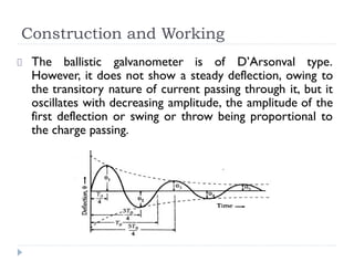
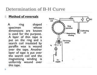
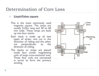
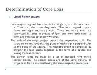
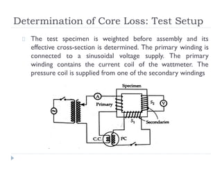
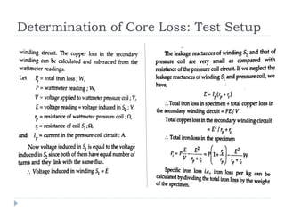
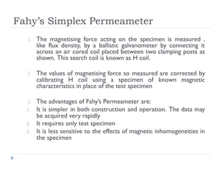
SlideShare a Scribd company logo
1 of 64
Download to read offline
MODULE 4
Prepared by
JEENA JOHN,ASST. PROF. IN EEE, SOE, CUSAT
Magnetic Measurements
Ballistic Galvanometer
It is used for measurement of quantity of electricity
(charge) passed through it. In magnetic measurements,
this quantity of electricity is due to an instantaneous emf
induced in a search coil connected across the ballistic
galvanometer
The instantaneous emf is induced in the search coil when
the flux linking with the search coil is changed. The
quantity of electricity passing through the galvanometer
is proportional to the emf induced and hence to the
change in flux linking with the search coil.
The galvanometer can therefore be calibrated to read
the charge directly.
Construction and Working
The ballistic galvanometer is of D’Arsonval type.
However, it does not show a steady deflection, owing to
the transitory nature of current passing through it, but it
oscillates with decreasing amplitude, the amplitude of the
first deflection or swing or throw being proportional to
the charge passing.
Construction and Working
The proportionality between the throw of the galvanometer and
the charge passing holds good only if the whole charge passes
through the galvanometer coil before any appreciable deflection of
the coil takes place.
This condition can be satisfied if the time taken by the charge to
pass is small and the period of the undamped oscillations of the
galvanometer is large. The time period for undamped oscillations of
a galvanometer is:
Thus to have a long time period, the moment of inertia J of the
moving system should be large and the control constant of the
suspension K should be small.
The above conditions can be satisfied by attaching small weights to
the moving system in order to increase its moment of inertia and
by using suspensions of smaller stiffness so as to decrease the
control constant K
Construction and Working
The damping of galvanometer should be small in order that
the amplitude of the first swing is large. After the first swing
has been observed, electromagnetic damping may be used to
bring the coil rapidly to rest.
This can be done by having a key connected across the
galvanometer terminals : this key short circuits the
galvanometer coil when closed. This is because the
electromagnetic torque produced on movement of the coil is
inversely proportional to resistance.
When the coil is short circuited, the resistance in the circuit
is only that of coil, which is small and so a large damping
torque is produced which brings the coil to rest in a short
time.
Except for the above special features the construction of a
ballistic galvanometer is similar to a D’Arsonval type
galvanometer
Hibbert Magnetic Standard
It consists of a circular bar magnet
and an iron yoke which have a
narrow annular gap between them.
A brass tube carrying a coil can
slide through the gap. The brass
tube is taken to its top position and
is then released with the help of a
trigger
It falls under gravity and as it slides
through the gap, its coil cuts
through the magnetic field of the
permanent magnet and therefore an
emf is produced in the coil.
Hibbert Magnetic Standard
The coil is connected across the terminals of a ballistic
galvanometer. The throw of the BG can be observed.
The rate at which the coil cuts through the field is
constant for a particular apparatus. Thus emf per turn is
constant.
By the use of the standard the flux linkages which
produce an observed throw of the galvanometer can be
known by knowing the airgap flux and the number of
turns in the coil. Hence the galvanometer constant can
be evaluated.
Flux Meter : Construction
It is a special type of ballistic galvanometer
in which the controlling torque is very
small and the electromagnetic damping is
heavy.
The construction is similar to a moving coil
milli ammeter. A coil of small cross-section
is suspended from a spring support by
means of a single silk thread. The coil
moves in the narrow gap of a permanent
magnet. There are no control springs
The current is led into the coil with the
help of a very loose helices of very thin,
annealed silver strips. The controlling
torque is thus reduced to minimum. The
coil is formerless and the air friction
damping is negligible
Flux Meter : Operation
The terminals of the flux meter are connected to a search
coil. The flux linking with the search coil is changed either by
removing the coil from the magnetic field or by reversing the
field. Due to change in the value of flux linking with the
search coil an emf is induced in it.
This emf sends a current through the flux meter which
deflects through an angle depending upon the change in the
value of flux linkages.
The instrument coil deflects during the period the flux
linkages change but as soon as the change ceases the coil
stops, owing to high electromagnetic damping in the coil
circuit. This high electromagnetic damping is obtained by
having a low resistance of the circuit comprising the flux
meter and the search coil.
Flux Meter: Advantages &Disadvantages
Advantages :
1. The industrial form of fluxmeter is portable.
2. Its scale is directly calibrated in weber turns
3. The indication of the meter is independent of the time
taken by the flux change. This is of great importance in
measurement of flux linking with highly inductive
circuits where the flux changes may be relatively slow
rendering the use of BGs impractical.
Disadvantages :
The fluxmeter is less sensitive and accurate than the
ballistic galvanometer.
Magnetic Measurements
Principal requirements in magnetic measurements are:
1. The measurement of magnetic field strength in air
2. The determination of B-H curve and hysteresis loop
for soft ferromagnetic materials.
3. The determination of eddy current and hysteresis
losses of soft ferromagnetic materials subjected to
alternating magnetic fields.
4. The testing of permanent magnets
Magnetic Measurements
Magnetic measurements have some inherent inaccuracies
due to which the measured values depart considerably
from the true values. The inaccuracies are due to the
following reasons:
1. The conditions in the magnetic specimen under test
are different from those assumed in calculations
2. The magnetic materials are not homogeneous
3. There is no uniformity between different batches of
test specimens even if such batches are of the same
composition
Determination of B-H Curve
Method of reversals
A ring shaped
specimen whose
dimensions are known
is used for the purpose.
A layer of thin tape is
put on the ring and a
search coil insulated by
paraffin wax is wound
over the tape. Another
layer of tape is put over
the search coil and the
magnetising winding is
uniformly wound over
this tape.
Determination of B-H Curve
Method of reversals
After demagnetizing the test is started by setting the magnetizing
current to its lowest test value. With the galvanometer key K
closed, the iron specimen is brought into a reproducible cyclic
magnetic state by throwing the reversing switch S backward and
forward for about 20 times.
Key K is now opened and the value of flux corresponding to this
value of H is measured by reversing the switch S and noting the
throw of galvanometer. The value of flux density corresponding to
this H can be calculated by dividing the flux by the area of the
specimen
The above procedure is repeated for various values of H upto the
maximum testing point. The B-H curve may be plotted from the
measured values of B corresponding to the various values of H.
Determination of B-H Curve
Step by step method
The magnetising winding
is supplied through a
potential divider having a
large number of tappings.
The tappings are arranged
so that the magnetising
force H may be increased,
in a number of suitable
steps, upto the desired
maximum value. The
specimen before being
tested is demagnetised.
Determination of B-H Curve
Step by step method
The tapping switch S2 is set on tapping 1 and the switch S1 is
closed. The throw of the galvanometer corresponding to this
increase in flux density in the specimen from zero to some
value B1 is observed.
The value of B1 can be calculated from the throw of the
galvanometer. The value of corresponding magnetising force
H1 may be calculated from the value of current flowing in the
magnetising winding at tapping 1. The magnetising force is
then increased to H2 by switching S2 suddenly to tapping 2,
and the corresponding increase in flux density ∆B is
determined from the throw of the galvanometer.
Determination of B-H Curve
Step by step method
Then flux density B2
corresponding to
magnetising force H2 is given
by B1+∆B. This process is
repeated for other values of
H upto the maximum point
and the complete B-H curve
is obtained
Determination of Hysteresis Loop
Step by step method
The determination of hysteresis loop
by this method is done by simply
continuing the procedure for
determination of B-H curve. After
reaching the point of maximum H, ie,
when switch S2 is at tapping 10, the
magnetising current is next reduced, in
steps to zero by moving switch S2
down through the tapping points 9, 8,
7….3,2,1. After reduction of
magnetising force to zero, negative
values of H are obtained by reversing
the supply to potential divider and
then moving the switch S2 up again in
order 1,2,3….8,9,10.
Determination of Core Loss
Wattmeter method
This method is most commonly used for measurement of iron
loss in strip(sheet) material. The strip material to be tested is
assembled as a closed magnetic circuit in the form of a square.
Therefore this arrangement is known as magnetic square. There
ate two common forms of this magnetic squares.
1. Epstein square
In this square there are four stacks of
strips. These stacks are bound and then
taped. The individual strips are insulated
from each other and each strip is in the
plane of the square. The stacks are slipped
into four magnetising coils with the strips
projecting beyond the coils. The ends of
the four strips are interleaved (as in
transformer core construction) and
clamped at corners
Determination of Core Loss
2. Lloyd-Fisher square
This is the most commonly used
magnetic square. The strips are
usually 0.25m long and 50 to 60
mm wide. These strips are built
up into four stacks.
Each stack is made up of two
types of strips- one cut in the
direction of rolling and the other
cut perpendicular to the
direction of rolling.
The stacks or strips are placed
inside four similar magnetising
coils of large cross-sectional area.
These four coils are connected
in series to form the primary
winding.
Determination of Core Loss
2. Lloyd-Fisher square
Each magnetising coil has two similar single layer coils underneath
it. They are called secondary coils. Thus in a magnetic square
there are eight secondary coils. These secondary coils are
connected in series in groups of four, one from each core, to
form two separate secondary windings.
The ends of the strips project beyond the magnetising coils. The
strips are so arranged that the plane of each strip is perpendicular
to the plane of the square. The magnetic circuit is completed by
bringing the four stacks together in the form of a square and
joining them at corners.
The corner joints are made by a set of standard right angled
corner pieces. The corner pieces are of the same material as
strips or at least a material having the same magnetic properties.
Lloyd-Fisher Square
Advantages:
1. In case allowance for corner pieces is known with sufficient
accuracy, the Lloyd-Fisher square gives rather more reliable
results than the Epstein square. In the case of Epstein square,
the value of flux density in the corners is quite different from
that of the square and an allowance of this is difficult to
make.
2. The Epstein square is also inferior for tests on anistropic
materials as the direction of flux at the corners is partially
perpendicular to the path of flux in other portions of the
strip. The use of corner piece in a Lloyd-Fisher square makes
it superior for testing anisotropic materials.
Determination of Core Loss: Test Setup
The test specimen is weighted before assembly and its
effective cross-section is determined. The primary winding is
connected to a sinusoidal voltage supply. The primary
winding contains the current coil of the wattmeter. The
pressure coil is supplied from one of the secondary windings
Determination of Core Loss: Test Setup
The wattmeter is designed for low power factor operation
as the power factor is usually about 0.2. The second
secondary winding supplies an electrostatic voltmeter or an
electrodynamic voltmeter of very high impedance. The
frequency of supply is adjusted to the correct value
The voltage applied to the primary winding is adjusted,
preferably with the help of a variable ratio transformer, till
the magnetising current is adjusted to give the required value
of Bm. The wattmeter and voltmeter readings are observed.
Determination of Core Loss: Test Setup
Fahy’s Simplex Permeameter
This permeameter is commonly used
for routine testing of magnetic
materials.
It consists of a single specimen in the
form of a bar. The specimen is
clamped against a laminated steel
yoke with the help of two iron posts.
The yoke carries a magnetising
winding.
The specimen is wound uniformly
with a search coil which extends
over its entire active length. This
search coil is connected to a ballistic
galvanometer for the measurement
of flux density and therefore this coil
is known as B coil.
Fahy’s Simplex Permeameter
The magnetising force acting on the specimen is measured ,
like flux density, by a ballistic galvanometer by connecting it
across an air cored coil placed between two clamping posts as
shown. This search coil is known as H coil.
The values of magnetising force so measured are corrected by
calibrating H coil using a specimen of known magnetic
characteristics in place of the test specimen
The advantages of Fahy’s Permeameter are:
1. It is simpler in both construction and operation. The data may
be acquired very rapidly
2. It requires only test specimen
3. It is less sensitive to the effects of magnetic inhomogeneities in
the specimen
Cathode Ray Oscilloscope (CRO)
CRO - Introduction
CRO is a very useful and
versatile laboratory
instrument used for
display, measurement and
analysis of waveforms and
other phenomena in
electrical and electronic
circuits
CROs are in fact very fast
X-Y plotters, displaying
an input signal versus
another signal or versus
time
Cathode Ray Tube (CRT)
The main parts of a CRT are :
1. Electron Gun Assembly
2. Deflection Plate Assembly
3. Fluorescent Screen
4. Glass Envelope
5. Base, trough which connections are made to various parts
Electron Gun Assembly
It produces a sharply focused beam of electrons which are
accelerated to high velocity
The electron gun, which emits electrons and forms them into a
beam consists of a heater, a cathode, a grid , a pre-accelerating
anode, a focusing anode and an accelerating anode
Electrons are emitted from indirectly heated cathode. A layer of
Barium and Strontium oxide is deposited on the end of the
cathode – which is a cylinder to obtain high emissions of electrons
at moderate temperature
These electrons pass through a small hole in the control grid. This
control is usually a nickel cylinder, with a centrally located hole, co-
axial with the CRT axis
Electron Gun Assembly (Ctnd…)
The intensity of electron beam depends upon the number of
electrons emitted from the cathode. The grid with its
negative bias controls the number of electrons emitted from
the cathode and hence the intensity is controlled by grid
The electrons are accelerated by the high positive potential
which is applied to the pre-accelerating and accelerating
anodes
The electron beam is focused by the focusing anode. There
are two methods of focusing an electron beam:
i. Electrostatic focusing
ii. Electromagnetic focusing
Deflection Plates
The electron beam, after leaving the electron gun, passes
through two pairs of deflection plates
One pair of plates is mounted horizontally and produces an
electric field in the vertical plane. This pair produces a vertical
deflection and is thus called Vertical Deflection Plates or Y
Plates
The other pair of plates is mounted vertically and produces a
horizontal deflection. This pair of plates is called Horizontal
Deflection Plates or X Plates
The plates are flared so as to allow the beam to pass through
them without striking the plates
Screen for CRTs
The front of CRT is called the face plate. It is formed by
pressing molten glass in mould and then annealing it. Some
CRTs have a face plate made entirely from fibre optics.
The inside surface of the face plate is coated with phosphor.
This consists of very pure inorganic crystalline phosphor
crystals, to which traces of other elements, called activators,
have been added
Activators affect the characteristics of phosphor, such as its
luminous efficiency, spectral emission and persistence
A phosphor converts electrical energy to light energy. When
an Electron beam strikes phosphor crystals it raises their
energy level. This is known as cathodoluminescence
Screen for CRTs (Cntd…)
Light is emitted during phosphor excitation and is called
fluorescence.
When the electron beam is switched off the phosphor crystals
return to their initial state, and release a quantum of light energy.
This is called phosphorescence or persistence
Graticule : It is a grid of lines that serves as a scale when making
time and amplitude measurements
Aquadag : The bombarding electrons, striking the screen release
secondary emission electrons. These secondary electrons are
collected by an aqueous solution of graphite called Aquadag.
Collection of secondary electrons is necessary to keep the CRT
screen in a state of electrical equilibrium.
Time Base Generator Circuit
Oscilloscopes are generally used to
display a waveform that varies as a
function of time.
If the waveform is to be accurately
reproduced, the beam must have a
constant horizontal velocity. Since beam
velocity is a function of deflecting
voltage, the deflecting voltage must
increase linearly with time.
A voltage with this characteristic is
called a ramp voltage. If the voltage
decreases rapidly to zero with the
waveform repeatedly reproduced, the
pattern is called a sawtooth waveform
Time Base Generator Circuit (Cntd..)
During the sweep time, Ts, the beam moves from left to right
across the CRT screen. The beam is deflected to the right by the
increasing amplitude of the ramp voltage and the fact that positive
voltage attracts the negative electrons.
During the retrace time or flyback time Tr, the beam returns
quickly to the left side of the screen. The control grid is gated off,
which blanks out the beam during retrace time and prevents an
undesirable retrace pattern from appearing on the screen
Since signals of different frequencies will be observed with the
oscilloscope, the sweep rate must be adjustable. We can change
the sweep rate in steps by switching different capacitors into the
circuit. The front panel control for this adjustment is marked time/
div or sec/div
Simple Sawtooth Generator
This is a simple sweep circuit in which
capacitor C charges through the
resistor R. The capacitor discharges
periodically through transistor Q1
When the transistor is turned on
completely , it presents a low-
resistance discharge path through
which the capacitor discharges quickly.
If the transistor is not turned on the
capacitor will charge exponentially to
the supply voltage Vcc according to
the equation,
Basic CRO Circuit
Basic CRO Circuits (Cntd…)
1) Vertical (Y) Deflection system : The signals to be examined
are usually applied to the vertical or Y deflection plates through
an input attenuator and a number of amplifier stages.
Vertical amplifier is required because the signals are not strong
enough to produce measurable deflection on the CRT screen.
The amplifier response must be wide enough to pass faithfully
the entire band of frequencies to be measured.
When high voltage signals are to be examined, they must be
attenuated to bring them within the range of vertical amplifiers
.
The vertical amplifier output is also applied to the synchronizing
amplifier through the synchronizer selector switch in the internal
position. This permits the horizontal sweep circuit to be
triggered by the signal being investigated
Basic CRO Circuits (Cntd…)
2) Horizontal (X) Deflection system : The horizontal
deflection plates are fed by a sweep voltage that provides a time
base.
The horizontal plates are supplied through an amplifier, but they
can be fed directly when voltages are of sufficient magnitude.
When external signals are to be applied to the horizontal
deflection system, they can also be fed through the horizontal
amplifier, via the sweep selector switch in the external position
.
When the sweep selector switch is in the internal position, the
horizontal amplifier receives an input from the sawtooth sweep
generator which is triggered by synchronizing amplifier
Basic CRO Circuits (Cntd…)
3) Synchronization : Whatever type of sweep is used, it must be
synchronized with the signal being measured. Synchronization has
to be done to obtain a pattern. This requires that the time base
be operated at a sub multiple frequency of the signal under
measurement. If synchronization is not done, the pattern is not
stationary, but appears to drift across the screen in random
fashion
Sources of Synchronization:
i. Internal : In this type of synchronization, the trigger is obtained
from the signal being measured through the vertical amplifier
ii. External : In this method, an external trigger source is also used
to trigger or initiate the signal being measured
iii. Line : In this case, the trigger is obtained from the power supply
to the CRO (say 230V, 50Hz)
Basic CRO Circuits (Cntd…)
4) Blanking circuit : The sawtooth sweep voltage applied to the X
plates moves the beam across the CRT tube in a straight
horizontal line from left to right during the sweep trace time, Ts
A comparatively slow movement of spot will appear as a solid line,
provided the rate of movement exceeds the threshold of
persistence of vision. Below this threshold limit, a moving spot is
perceived.
On the other hand, the comparatively rapid movement of spot
will appear as a thin and dim line, or may be invisible. Thus if the
retrace or flyback time is very small the spot remains invisible.
In an ideal case, the flyback time, Tr is zero and hence the spot
while moving from right to left remains invisible
Basic CRO Circuits (Cntd…)
However in actual practice the flyback time is not zero and
therefore the retrace may cause confusion. Thus the retrace
should be eliminated or blanked out.
The retrace is blanked out by applying a high negative voltage to
the grid during flyback period Tr .The blanking voltage is usually
developed by sweep generator.
5) Intensity (Z-axis) Modulation: It is done by inserting a signal
between the ground and the cathode. It is applied during
normally visible portion of the trace
The Z-axis modulation can be used for brightening the display.
Periodic positive pulses are applied to the grid to brighten the
beam during its sweep period. These periodically brightened
spots may be used as markers for time calibration of the main
waveform
Basic CRO Circuits (cntd…)
6) Positioning Controls : It is necessary to provide some means
of positioning the trace on the screen. The positioning of the
trace is done by applying small independent, internal dc voltages
to the deflecting plates and control can be exercised by varying
the voltage with help of potentiometers
7) Focus Control : The focusing electrode acts like a lens whose
focal length can be changed. This change can be brought about by
changing the potential of the focusing anode
8) Intensity Control : The intensity of the beam is varied by the
Intensity control potentiometer which changes the grid potential
with respect to cathode. The grid potential determines the
amount of electrons leaving the cathode and thus controls the
intensity of the beam
Basic CRO Circuits (cntd…)
9) Calibration circuit : Laboratory oscilloscopes
normally have an internally generated and stabilized
voltage of known amplitude which is used for
calibration purposes. Usually the calibrating voltage has
a square waveform
10) Astigmatism : This is used to correct an effect
which exactly is analogous to astigmatism in optical
lenses. To focus the spot correctly, it is necessary to
stop it near the centre of the screen by switching off
the time base and adjusting the X and Y positioning
controls. The spot is then made as sharp as possible by
successive adjustment of focus and astigmatism controls
Dual Trace Oscilloscope
Dual Trace Oscilloscope(cntd…)
There are two separate vertical input channels, A and B,
and these use separate attenuator and pre-amplifier
stages. Therefore, the amplitude of each input, as viewed
on the oscilloscope, can be individually controlled
After preamplification the two channels meet at an
electronic switch. This has the ability to pass one channel
at a time into the vertical amplifier, via the delay line.
There are two common operating modes for the
electronic switch, called alternate and chop and these are
selected from the front panel of instrument
Dual Trace Oscilloscope(cntd…)
Switch S2 allows the circuit to be triggered on either the A
or B channel waveforms, or on line frequency, or on an
external signal.
The horizontal amplifier can be fed from the sweep generator,
or the B channel via switch S1. This is the X-Y mode and the
oscilloscope operates from channel A as the vertical signal
and channel B as horizontal signal, giving very accurate X-Y
measurements
Several operating modes can be selected from the front panel
for display such as channel A only, channel B only, channels A
and B as two traces, etc
Dual Beam Oscilloscope
Dual Beam Oscilloscope (Cntd…)
The dual trace oscilloscope cannot capture two fast transient
events, as it cannot switch quickly enough between traces.
The dual beam oscilloscope has two separate electron beams,
and therefore two completely separate vertical channels
The two channels may have a common time base system or
independent time base circuits. An independent time base
allows different sweep rates for the two channels but
increases the size and weight of the oscilloscope
Two methods are used for generating the two electron beams
within the CRT. The first method uses a double gun tube.
This allows brightness and focus of each beam to be
controlled separately but is bulkier than a split beam tube
Dual Beam Oscilloscope (Cntd…)
In the second method, known as split beam, a single
electron gun is used. A horizontal splitter plate is placed
between the last anode and the Y deflection plates and
isolates the two channels
The split beam arrangement has half the brightness of a
single beam, which has disadvantages at high frequency
operation. Also the two display may have noticeably
different brightness, if operated at widely spaced sweep
speeds
Measurement of Voltages & Currents
The Y-shift control is adjusted so that positive peak of the
test voltage coincides with some datum line on the screen;
the shift control is then operated until the negative peak
coincides with the datum
The movement of the control is arranged to read directly the
peak-to-peak voltage. When dealing with sinusoidal voltages,
the rms value is given by dividing the peak-to-peak voltage by
2√2
The value of current can be obtained by measuring the
voltage drop across a known resistance connected in the
circuit
Measurement of Phase & Frequency
When sinusoidal voltages are simultaneously applied to the
vertical and horizontal plates, the patterns that appear on the
screen of a CRT are called Lissajous Patterns
When two sinusoidal voltages of equal frequency which are in
phase with each other are applied to the horizontal and
vertical deflection plates, the pattern appearing on the screen
is a straight line.
When two equal voltages of equal frequency but with 90
degree phase displacement are applied to a CRO, the trace
on the screen is a circle
Measurement of Phase & Frequency
When two equal voltages of equal frequency but with a
phase shift ϕ are applied to a CRO we obtain an
ellipse. An ellipse is also obtained when unequal
voltages of same frequency are applied to the
CRO
Regardless of the two amplitudes of the applied
voltages the ellipse provides a simple means of
finding phase difference between two voltages.
The sine of the phase angle between the voltages
is given by
Measurement of Phase & Frequency
For convenience, the gains of the vertical and
horizontal amplifiers are adjusted so that the
ellipse fits exactly into a square marked by the
lines on the graticule
If the major axis of the ellipse lies in the first
and third quadrants, ie its slope is positive, the
phase angle is either between 0° to 90° or
between 270° to 360°
When the major axis of the ellipse lies in second
and fourth quadrants, ie when its slope is
negative, the phase angle is either between 90°
and 180° or between 180° and
270°
Frequency Measurements
The signal whose frequency is to be measured is
applied to the Y plates. An accurately calibrated
standard variable frequency source is used to
supply voltage to the X plates, with the internal
sweep generator switched off
The standard frequency is adjusted until the
pattern appears as a circle or an ellipse,
indicating that both signals are of the same
frequency
Where it is not possible to adjust the standard
signal frequency to the exact frequency of the
unknown signal, the standard is adjusted to
multiple or sub multiple of the unknown source
so that the pattern appears stationary
Frequency Measurements (Example)
Let the frequency of the wave
applied to the Y plates is twice that
of the voltage applied to X plates
This means that the CRT spot travels
two complete cycles in the vertical
direction against one in the
horizontal direction
The two waves start at the same
instant. Lissajous pattern may be
constructed in the usual way and a 8
shaped pattern with two loops is
obtained
If the two waves donot start at the
same instant we get different
patterns for the same frequency ratio
Frequency Measurements (Example)
It can be shown that for all the
above cases, the ratio of the two
frequencies is
The above rule, however , doesnot
hold for the Lissajous pattern with
free ends.
Frequency Measurements (Example)
Two lines are drawn, one horizontal and the
other vertical so that they donot pass through
any intersections of different parts of the
Lissajous curve
The number of intersections of the horizontal
and the vertical lines with The Lissajous curve
are individually counted
The frequency ratio is given by
The ratio of frequencies when open ended
Lissajous patterns are obtained can also be
found by treating the open ends as half
tangencies
5:2

More Related Content

Similar to Electrical measurements and measuring instruments

Impulse current
Impulse currentImpulse current
Impulse currentsarunkutti
 
Unit 5 part 2 of transducers and it's importance
Unit 5 part 2 of transducers and it's importanceUnit 5 part 2 of transducers and it's importance
Unit 5 part 2 of transducers and it's importanceReshmaJose25
 
Microsoft PowerPoint - Unit II.pdf
Microsoft PowerPoint - Unit II.pdfMicrosoft PowerPoint - Unit II.pdf
Microsoft PowerPoint - Unit II.pdfsrevathiap
 
measurement of high voltage and high currents
 measurement of high voltage and high currents  measurement of high voltage and high currents
measurement of high voltage and high currents mukund mukund.m
 
What is Magnetron? Working Principle of Balanced Bolometer Bridge method for ...
What is Magnetron? Working Principle of Balanced Bolometer Bridge method for ...What is Magnetron? Working Principle of Balanced Bolometer Bridge method for ...
What is Magnetron? Working Principle of Balanced Bolometer Bridge method for ...AL- AMIN
 
PMRF_TA_LINEAR_AND_ANGULAR_MEASUREMENTS.pptx
PMRF_TA_LINEAR_AND_ANGULAR_MEASUREMENTS.pptxPMRF_TA_LINEAR_AND_ANGULAR_MEASUREMENTS.pptx
PMRF_TA_LINEAR_AND_ANGULAR_MEASUREMENTS.pptxJeevaJeeva410662
 
Permanent Magnet Moving Coil (PPMC)
Permanent Magnet Moving Coil (PPMC)Permanent Magnet Moving Coil (PPMC)
Permanent Magnet Moving Coil (PPMC)Shubham Mohindru
 
Ch20 Electromagnetic Induction
Ch20 Electromagnetic InductionCh20 Electromagnetic Induction
Ch20 Electromagnetic InductionRohit Mohd
 
Linear and angular measurement
Linear and angular measurementLinear and angular measurement
Linear and angular measurementEr Ashvin Deogade
 
Electromagnetism
ElectromagnetismElectromagnetism
ElectromagnetismChoong Hong
 
Electromagnetic induction
Electromagnetic inductionElectromagnetic induction
Electromagnetic inductionUgyenNamgay4
 
High direct current measurement
High direct current measurementHigh direct current measurement
High direct current measurementMd Ibrahim Khalil
 
single phase energy meter.pptx
single phase energy meter.pptxsingle phase energy meter.pptx
single phase energy meter.pptxtadi1padma
 
Unit 3- DC Machines.pdf
Unit 3- DC Machines.pdfUnit 3- DC Machines.pdf
Unit 3- DC Machines.pdfdeepaMS4
 
Ch 22 Electromagnetic Induction
Ch 22 Electromagnetic InductionCh 22 Electromagnetic Induction
Ch 22 Electromagnetic InductionScott Thomas
 
4_Inductance, Energy.pptx
4_Inductance, Energy.pptx4_Inductance, Energy.pptx
4_Inductance, Energy.pptxSungaleliYuen
 
4_Inductance, Energy.pptx
4_Inductance, Energy.pptx4_Inductance, Energy.pptx
4_Inductance, Energy.pptxSungaleliYuen
 

Similar to Electrical measurements and measuring instruments (20)

Impulse current
Impulse currentImpulse current
Impulse current
 
Unit 5 part 2 of transducers and it's importance
Unit 5 part 2 of transducers and it's importanceUnit 5 part 2 of transducers and it's importance
Unit 5 part 2 of transducers and it's importance
 
Hall effect
Hall effectHall effect
Hall effect
 
Microsoft PowerPoint - Unit II.pdf
Microsoft PowerPoint - Unit II.pdfMicrosoft PowerPoint - Unit II.pdf
Microsoft PowerPoint - Unit II.pdf
 
Lecture 6.pdf
Lecture 6.pdfLecture 6.pdf
Lecture 6.pdf
 
measurement of high voltage and high currents
 measurement of high voltage and high currents  measurement of high voltage and high currents
measurement of high voltage and high currents
 
What is Magnetron? Working Principle of Balanced Bolometer Bridge method for ...
What is Magnetron? Working Principle of Balanced Bolometer Bridge method for ...What is Magnetron? Working Principle of Balanced Bolometer Bridge method for ...
What is Magnetron? Working Principle of Balanced Bolometer Bridge method for ...
 
PMRF_TA_LINEAR_AND_ANGULAR_MEASUREMENTS.pptx
PMRF_TA_LINEAR_AND_ANGULAR_MEASUREMENTS.pptxPMRF_TA_LINEAR_AND_ANGULAR_MEASUREMENTS.pptx
PMRF_TA_LINEAR_AND_ANGULAR_MEASUREMENTS.pptx
 
Permanent Magnet Moving Coil (PPMC)
Permanent Magnet Moving Coil (PPMC)Permanent Magnet Moving Coil (PPMC)
Permanent Magnet Moving Coil (PPMC)
 
Ch20 Electromagnetic Induction
Ch20 Electromagnetic InductionCh20 Electromagnetic Induction
Ch20 Electromagnetic Induction
 
Linear and angular measurement
Linear and angular measurementLinear and angular measurement
Linear and angular measurement
 
Pressure Measurement Part II
Pressure Measurement   Part IIPressure Measurement   Part II
Pressure Measurement Part II
 
Electromagnetism
ElectromagnetismElectromagnetism
Electromagnetism
 
Electromagnetic induction
Electromagnetic inductionElectromagnetic induction
Electromagnetic induction
 
High direct current measurement
High direct current measurementHigh direct current measurement
High direct current measurement
 
single phase energy meter.pptx
single phase energy meter.pptxsingle phase energy meter.pptx
single phase energy meter.pptx
 
Unit 3- DC Machines.pdf
Unit 3- DC Machines.pdfUnit 3- DC Machines.pdf
Unit 3- DC Machines.pdf
 
Ch 22 Electromagnetic Induction
Ch 22 Electromagnetic InductionCh 22 Electromagnetic Induction
Ch 22 Electromagnetic Induction
 
4_Inductance, Energy.pptx
4_Inductance, Energy.pptx4_Inductance, Energy.pptx
4_Inductance, Energy.pptx
 
4_Inductance, Energy.pptx
4_Inductance, Energy.pptx4_Inductance, Energy.pptx
4_Inductance, Energy.pptx
 

Recently uploaded

(ANVI) Koregaon Park Call Girls Just Call 7001035870 [ Cash on Delivery ] Pun...
(ANVI) Koregaon Park Call Girls Just Call 7001035870 [ Cash on Delivery ] Pun...(ANVI) Koregaon Park Call Girls Just Call 7001035870 [ Cash on Delivery ] Pun...
(ANVI) Koregaon Park Call Girls Just Call 7001035870 [ Cash on Delivery ] Pun...ranjana rawat
 
Top Rated Pune Call Girls Budhwar Peth ⟟ 6297143586 ⟟ Call Me For Genuine Se...
Top Rated  Pune Call Girls Budhwar Peth ⟟ 6297143586 ⟟ Call Me For Genuine Se...Top Rated  Pune Call Girls Budhwar Peth ⟟ 6297143586 ⟟ Call Me For Genuine Se...
Top Rated Pune Call Girls Budhwar Peth ⟟ 6297143586 ⟟ Call Me For Genuine Se...Call Girls in Nagpur High Profile
 
Sheet Pile Wall Design and Construction: A Practical Guide for Civil Engineer...
Sheet Pile Wall Design and Construction: A Practical Guide for Civil Engineer...Sheet Pile Wall Design and Construction: A Practical Guide for Civil Engineer...
Sheet Pile Wall Design and Construction: A Practical Guide for Civil Engineer...Dr.Costas Sachpazis
 
UNIT-II FMM-Flow Through Circular Conduits
UNIT-II FMM-Flow Through Circular ConduitsUNIT-II FMM-Flow Through Circular Conduits
UNIT-II FMM-Flow Through Circular Conduitsrknatarajan
 
CCS335 _ Neural Networks and Deep Learning Laboratory_Lab Complete Record
CCS335 _ Neural Networks and Deep Learning Laboratory_Lab Complete RecordCCS335 _ Neural Networks and Deep Learning Laboratory_Lab Complete Record
CCS335 _ Neural Networks and Deep Learning Laboratory_Lab Complete RecordAsst.prof M.Gokilavani
 
Call Girls in Nagpur Suman Call 7001035870 Meet With Nagpur Escorts
Call Girls in Nagpur Suman Call 7001035870 Meet With Nagpur EscortsCall Girls in Nagpur Suman Call 7001035870 Meet With Nagpur Escorts
Call Girls in Nagpur Suman Call 7001035870 Meet With Nagpur EscortsCall Girls in Nagpur High Profile
 
(PRIYA) Rajgurunagar Call Girls Just Call 7001035870 [ Cash on Delivery ] Pun...
(PRIYA) Rajgurunagar Call Girls Just Call 7001035870 [ Cash on Delivery ] Pun...(PRIYA) Rajgurunagar Call Girls Just Call 7001035870 [ Cash on Delivery ] Pun...
(PRIYA) Rajgurunagar Call Girls Just Call 7001035870 [ Cash on Delivery ] Pun...ranjana rawat
 
VIP Call Girls Service Hitech City Hyderabad Call +91-8250192130
VIP Call Girls Service Hitech City Hyderabad Call +91-8250192130VIP Call Girls Service Hitech City Hyderabad Call +91-8250192130
VIP Call Girls Service Hitech City Hyderabad Call +91-8250192130Suhani Kapoor
 
UNIT - IV - Air Compressors and its Performance
UNIT - IV - Air Compressors and its PerformanceUNIT - IV - Air Compressors and its Performance
UNIT - IV - Air Compressors and its Performancesivaprakash250
 
Booking open Available Pune Call Girls Koregaon Park 6297143586 Call Hot Ind...
Booking open Available Pune Call Girls Koregaon Park  6297143586 Call Hot Ind...Booking open Available Pune Call Girls Koregaon Park  6297143586 Call Hot Ind...
Booking open Available Pune Call Girls Koregaon Park 6297143586 Call Hot Ind...Call Girls in Nagpur High Profile
 
College Call Girls Nashik Nehal 7001305949 Independent Escort Service Nashik
College Call Girls Nashik Nehal 7001305949 Independent Escort Service NashikCollege Call Girls Nashik Nehal 7001305949 Independent Escort Service Nashik
College Call Girls Nashik Nehal 7001305949 Independent Escort Service NashikCall Girls in Nagpur High Profile
 
UNIT-III FMM. DIMENSIONAL ANALYSIS
UNIT-III FMM.        DIMENSIONAL ANALYSISUNIT-III FMM.        DIMENSIONAL ANALYSIS
UNIT-III FMM. DIMENSIONAL ANALYSISrknatarajan
 
Structural Analysis and Design of Foundations: A Comprehensive Handbook for S...
Structural Analysis and Design of Foundations: A Comprehensive Handbook for S...Structural Analysis and Design of Foundations: A Comprehensive Handbook for S...
Structural Analysis and Design of Foundations: A Comprehensive Handbook for S...Dr.Costas Sachpazis
 
VIP Call Girls Service Kondapur Hyderabad Call +91-8250192130
VIP Call Girls Service Kondapur Hyderabad Call +91-8250192130VIP Call Girls Service Kondapur Hyderabad Call +91-8250192130
VIP Call Girls Service Kondapur Hyderabad Call +91-8250192130Suhani Kapoor
 
AKTU Computer Networks notes --- Unit 3.pdf
AKTU Computer Networks notes ---  Unit 3.pdfAKTU Computer Networks notes ---  Unit 3.pdf
AKTU Computer Networks notes --- Unit 3.pdfankushspencer015
 
Call Girls Pimpri Chinchwad Call Me 7737669865 Budget Friendly No Advance Boo...
Call Girls Pimpri Chinchwad Call Me 7737669865 Budget Friendly No Advance Boo...Call Girls Pimpri Chinchwad Call Me 7737669865 Budget Friendly No Advance Boo...
Call Girls Pimpri Chinchwad Call Me 7737669865 Budget Friendly No Advance Boo...roncy bisnoi
 
Introduction and different types of Ethernet.pptx
Introduction and different types of Ethernet.pptxIntroduction and different types of Ethernet.pptx
Introduction and different types of Ethernet.pptxupamatechverse
 
High Profile Call Girls Nagpur Isha Call 7001035870 Meet With Nagpur Escorts
High Profile Call Girls Nagpur Isha Call 7001035870 Meet With Nagpur EscortsHigh Profile Call Girls Nagpur Isha Call 7001035870 Meet With Nagpur Escorts
High Profile Call Girls Nagpur Isha Call 7001035870 Meet With Nagpur Escortsranjana rawat
 
High Profile Call Girls Nagpur Meera Call 7001035870 Meet With Nagpur Escorts
High Profile Call Girls Nagpur Meera Call 7001035870 Meet With Nagpur EscortsHigh Profile Call Girls Nagpur Meera Call 7001035870 Meet With Nagpur Escorts
High Profile Call Girls Nagpur Meera Call 7001035870 Meet With Nagpur EscortsCall Girls in Nagpur High Profile
 

Recently uploaded (20)

(ANVI) Koregaon Park Call Girls Just Call 7001035870 [ Cash on Delivery ] Pun...
(ANVI) Koregaon Park Call Girls Just Call 7001035870 [ Cash on Delivery ] Pun...(ANVI) Koregaon Park Call Girls Just Call 7001035870 [ Cash on Delivery ] Pun...
(ANVI) Koregaon Park Call Girls Just Call 7001035870 [ Cash on Delivery ] Pun...
 
Top Rated Pune Call Girls Budhwar Peth ⟟ 6297143586 ⟟ Call Me For Genuine Se...
Top Rated  Pune Call Girls Budhwar Peth ⟟ 6297143586 ⟟ Call Me For Genuine Se...Top Rated  Pune Call Girls Budhwar Peth ⟟ 6297143586 ⟟ Call Me For Genuine Se...
Top Rated Pune Call Girls Budhwar Peth ⟟ 6297143586 ⟟ Call Me For Genuine Se...
 
Sheet Pile Wall Design and Construction: A Practical Guide for Civil Engineer...
Sheet Pile Wall Design and Construction: A Practical Guide for Civil Engineer...Sheet Pile Wall Design and Construction: A Practical Guide for Civil Engineer...
Sheet Pile Wall Design and Construction: A Practical Guide for Civil Engineer...
 
UNIT-II FMM-Flow Through Circular Conduits
UNIT-II FMM-Flow Through Circular ConduitsUNIT-II FMM-Flow Through Circular Conduits
UNIT-II FMM-Flow Through Circular Conduits
 
CCS335 _ Neural Networks and Deep Learning Laboratory_Lab Complete Record
CCS335 _ Neural Networks and Deep Learning Laboratory_Lab Complete RecordCCS335 _ Neural Networks and Deep Learning Laboratory_Lab Complete Record
CCS335 _ Neural Networks and Deep Learning Laboratory_Lab Complete Record
 
Water Industry Process Automation & Control Monthly - April 2024
Water Industry Process Automation & Control Monthly - April 2024Water Industry Process Automation & Control Monthly - April 2024
Water Industry Process Automation & Control Monthly - April 2024
 
Call Girls in Nagpur Suman Call 7001035870 Meet With Nagpur Escorts
Call Girls in Nagpur Suman Call 7001035870 Meet With Nagpur EscortsCall Girls in Nagpur Suman Call 7001035870 Meet With Nagpur Escorts
Call Girls in Nagpur Suman Call 7001035870 Meet With Nagpur Escorts
 
(PRIYA) Rajgurunagar Call Girls Just Call 7001035870 [ Cash on Delivery ] Pun...
(PRIYA) Rajgurunagar Call Girls Just Call 7001035870 [ Cash on Delivery ] Pun...(PRIYA) Rajgurunagar Call Girls Just Call 7001035870 [ Cash on Delivery ] Pun...
(PRIYA) Rajgurunagar Call Girls Just Call 7001035870 [ Cash on Delivery ] Pun...
 
VIP Call Girls Service Hitech City Hyderabad Call +91-8250192130
VIP Call Girls Service Hitech City Hyderabad Call +91-8250192130VIP Call Girls Service Hitech City Hyderabad Call +91-8250192130
VIP Call Girls Service Hitech City Hyderabad Call +91-8250192130
 
UNIT - IV - Air Compressors and its Performance
UNIT - IV - Air Compressors and its PerformanceUNIT - IV - Air Compressors and its Performance
UNIT - IV - Air Compressors and its Performance
 
Booking open Available Pune Call Girls Koregaon Park 6297143586 Call Hot Ind...
Booking open Available Pune Call Girls Koregaon Park  6297143586 Call Hot Ind...Booking open Available Pune Call Girls Koregaon Park  6297143586 Call Hot Ind...
Booking open Available Pune Call Girls Koregaon Park 6297143586 Call Hot Ind...
 
College Call Girls Nashik Nehal 7001305949 Independent Escort Service Nashik
College Call Girls Nashik Nehal 7001305949 Independent Escort Service NashikCollege Call Girls Nashik Nehal 7001305949 Independent Escort Service Nashik
College Call Girls Nashik Nehal 7001305949 Independent Escort Service Nashik
 
UNIT-III FMM. DIMENSIONAL ANALYSIS
UNIT-III FMM.        DIMENSIONAL ANALYSISUNIT-III FMM.        DIMENSIONAL ANALYSIS
UNIT-III FMM. DIMENSIONAL ANALYSIS
 
Structural Analysis and Design of Foundations: A Comprehensive Handbook for S...
Structural Analysis and Design of Foundations: A Comprehensive Handbook for S...Structural Analysis and Design of Foundations: A Comprehensive Handbook for S...
Structural Analysis and Design of Foundations: A Comprehensive Handbook for S...
 
VIP Call Girls Service Kondapur Hyderabad Call +91-8250192130
VIP Call Girls Service Kondapur Hyderabad Call +91-8250192130VIP Call Girls Service Kondapur Hyderabad Call +91-8250192130
VIP Call Girls Service Kondapur Hyderabad Call +91-8250192130
 
AKTU Computer Networks notes --- Unit 3.pdf
AKTU Computer Networks notes ---  Unit 3.pdfAKTU Computer Networks notes ---  Unit 3.pdf
AKTU Computer Networks notes --- Unit 3.pdf
 
Call Girls Pimpri Chinchwad Call Me 7737669865 Budget Friendly No Advance Boo...
Call Girls Pimpri Chinchwad Call Me 7737669865 Budget Friendly No Advance Boo...Call Girls Pimpri Chinchwad Call Me 7737669865 Budget Friendly No Advance Boo...
Call Girls Pimpri Chinchwad Call Me 7737669865 Budget Friendly No Advance Boo...
 
Introduction and different types of Ethernet.pptx
Introduction and different types of Ethernet.pptxIntroduction and different types of Ethernet.pptx
Introduction and different types of Ethernet.pptx
 
High Profile Call Girls Nagpur Isha Call 7001035870 Meet With Nagpur Escorts
High Profile Call Girls Nagpur Isha Call 7001035870 Meet With Nagpur EscortsHigh Profile Call Girls Nagpur Isha Call 7001035870 Meet With Nagpur Escorts
High Profile Call Girls Nagpur Isha Call 7001035870 Meet With Nagpur Escorts
 
High Profile Call Girls Nagpur Meera Call 7001035870 Meet With Nagpur Escorts
High Profile Call Girls Nagpur Meera Call 7001035870 Meet With Nagpur EscortsHigh Profile Call Girls Nagpur Meera Call 7001035870 Meet With Nagpur Escorts
High Profile Call Girls Nagpur Meera Call 7001035870 Meet With Nagpur Escorts
 

Electrical measurements and measuring instruments

  • 1. MODULE 4 Prepared by JEENA JOHN,ASST. PROF. IN EEE, SOE, CUSAT
  • 3. Ballistic Galvanometer It is used for measurement of quantity of electricity (charge) passed through it. In magnetic measurements, this quantity of electricity is due to an instantaneous emf induced in a search coil connected across the ballistic galvanometer The instantaneous emf is induced in the search coil when the flux linking with the search coil is changed. The quantity of electricity passing through the galvanometer is proportional to the emf induced and hence to the change in flux linking with the search coil. The galvanometer can therefore be calibrated to read the charge directly.
  • 4. Construction and Working The ballistic galvanometer is of D’Arsonval type. However, it does not show a steady deflection, owing to the transitory nature of current passing through it, but it oscillates with decreasing amplitude, the amplitude of the first deflection or swing or throw being proportional to the charge passing.
  • 5. Construction and Working The proportionality between the throw of the galvanometer and the charge passing holds good only if the whole charge passes through the galvanometer coil before any appreciable deflection of the coil takes place. This condition can be satisfied if the time taken by the charge to pass is small and the period of the undamped oscillations of the galvanometer is large. The time period for undamped oscillations of a galvanometer is: Thus to have a long time period, the moment of inertia J of the moving system should be large and the control constant of the suspension K should be small. The above conditions can be satisfied by attaching small weights to the moving system in order to increase its moment of inertia and by using suspensions of smaller stiffness so as to decrease the control constant K
  • 6. Construction and Working The damping of galvanometer should be small in order that the amplitude of the first swing is large. After the first swing has been observed, electromagnetic damping may be used to bring the coil rapidly to rest. This can be done by having a key connected across the galvanometer terminals : this key short circuits the galvanometer coil when closed. This is because the electromagnetic torque produced on movement of the coil is inversely proportional to resistance. When the coil is short circuited, the resistance in the circuit is only that of coil, which is small and so a large damping torque is produced which brings the coil to rest in a short time. Except for the above special features the construction of a ballistic galvanometer is similar to a D’Arsonval type galvanometer
  • 7. Hibbert Magnetic Standard It consists of a circular bar magnet and an iron yoke which have a narrow annular gap between them. A brass tube carrying a coil can slide through the gap. The brass tube is taken to its top position and is then released with the help of a trigger It falls under gravity and as it slides through the gap, its coil cuts through the magnetic field of the permanent magnet and therefore an emf is produced in the coil.
  • 8. Hibbert Magnetic Standard The coil is connected across the terminals of a ballistic galvanometer. The throw of the BG can be observed. The rate at which the coil cuts through the field is constant for a particular apparatus. Thus emf per turn is constant. By the use of the standard the flux linkages which produce an observed throw of the galvanometer can be known by knowing the airgap flux and the number of turns in the coil. Hence the galvanometer constant can be evaluated.
  • 9. Flux Meter : Construction It is a special type of ballistic galvanometer in which the controlling torque is very small and the electromagnetic damping is heavy. The construction is similar to a moving coil milli ammeter. A coil of small cross-section is suspended from a spring support by means of a single silk thread. The coil moves in the narrow gap of a permanent magnet. There are no control springs The current is led into the coil with the help of a very loose helices of very thin, annealed silver strips. The controlling torque is thus reduced to minimum. The coil is formerless and the air friction damping is negligible
  • 10. Flux Meter : Operation The terminals of the flux meter are connected to a search coil. The flux linking with the search coil is changed either by removing the coil from the magnetic field or by reversing the field. Due to change in the value of flux linking with the search coil an emf is induced in it. This emf sends a current through the flux meter which deflects through an angle depending upon the change in the value of flux linkages. The instrument coil deflects during the period the flux linkages change but as soon as the change ceases the coil stops, owing to high electromagnetic damping in the coil circuit. This high electromagnetic damping is obtained by having a low resistance of the circuit comprising the flux meter and the search coil.
  • 11. Flux Meter: Advantages &Disadvantages Advantages : 1. The industrial form of fluxmeter is portable. 2. Its scale is directly calibrated in weber turns 3. The indication of the meter is independent of the time taken by the flux change. This is of great importance in measurement of flux linking with highly inductive circuits where the flux changes may be relatively slow rendering the use of BGs impractical. Disadvantages : The fluxmeter is less sensitive and accurate than the ballistic galvanometer.
  • 12. Magnetic Measurements Principal requirements in magnetic measurements are: 1. The measurement of magnetic field strength in air 2. The determination of B-H curve and hysteresis loop for soft ferromagnetic materials. 3. The determination of eddy current and hysteresis losses of soft ferromagnetic materials subjected to alternating magnetic fields. 4. The testing of permanent magnets
  • 13. Magnetic Measurements Magnetic measurements have some inherent inaccuracies due to which the measured values depart considerably from the true values. The inaccuracies are due to the following reasons: 1. The conditions in the magnetic specimen under test are different from those assumed in calculations 2. The magnetic materials are not homogeneous 3. There is no uniformity between different batches of test specimens even if such batches are of the same composition
  • 14. Determination of B-H Curve Method of reversals A ring shaped specimen whose dimensions are known is used for the purpose. A layer of thin tape is put on the ring and a search coil insulated by paraffin wax is wound over the tape. Another layer of tape is put over the search coil and the magnetising winding is uniformly wound over this tape.
  • 15. Determination of B-H Curve Method of reversals After demagnetizing the test is started by setting the magnetizing current to its lowest test value. With the galvanometer key K closed, the iron specimen is brought into a reproducible cyclic magnetic state by throwing the reversing switch S backward and forward for about 20 times. Key K is now opened and the value of flux corresponding to this value of H is measured by reversing the switch S and noting the throw of galvanometer. The value of flux density corresponding to this H can be calculated by dividing the flux by the area of the specimen The above procedure is repeated for various values of H upto the maximum testing point. The B-H curve may be plotted from the measured values of B corresponding to the various values of H.
  • 16. Determination of B-H Curve Step by step method The magnetising winding is supplied through a potential divider having a large number of tappings. The tappings are arranged so that the magnetising force H may be increased, in a number of suitable steps, upto the desired maximum value. The specimen before being tested is demagnetised.
  • 17. Determination of B-H Curve Step by step method The tapping switch S2 is set on tapping 1 and the switch S1 is closed. The throw of the galvanometer corresponding to this increase in flux density in the specimen from zero to some value B1 is observed. The value of B1 can be calculated from the throw of the galvanometer. The value of corresponding magnetising force H1 may be calculated from the value of current flowing in the magnetising winding at tapping 1. The magnetising force is then increased to H2 by switching S2 suddenly to tapping 2, and the corresponding increase in flux density ∆B is determined from the throw of the galvanometer.
  • 18. Determination of B-H Curve Step by step method Then flux density B2 corresponding to magnetising force H2 is given by B1+∆B. This process is repeated for other values of H upto the maximum point and the complete B-H curve is obtained
  • 19. Determination of Hysteresis Loop Step by step method The determination of hysteresis loop by this method is done by simply continuing the procedure for determination of B-H curve. After reaching the point of maximum H, ie, when switch S2 is at tapping 10, the magnetising current is next reduced, in steps to zero by moving switch S2 down through the tapping points 9, 8, 7….3,2,1. After reduction of magnetising force to zero, negative values of H are obtained by reversing the supply to potential divider and then moving the switch S2 up again in order 1,2,3….8,9,10.
  • 20. Determination of Core Loss Wattmeter method This method is most commonly used for measurement of iron loss in strip(sheet) material. The strip material to be tested is assembled as a closed magnetic circuit in the form of a square. Therefore this arrangement is known as magnetic square. There ate two common forms of this magnetic squares. 1. Epstein square In this square there are four stacks of strips. These stacks are bound and then taped. The individual strips are insulated from each other and each strip is in the plane of the square. The stacks are slipped into four magnetising coils with the strips projecting beyond the coils. The ends of the four strips are interleaved (as in transformer core construction) and clamped at corners
  • 21. Determination of Core Loss 2. Lloyd-Fisher square This is the most commonly used magnetic square. The strips are usually 0.25m long and 50 to 60 mm wide. These strips are built up into four stacks. Each stack is made up of two types of strips- one cut in the direction of rolling and the other cut perpendicular to the direction of rolling. The stacks or strips are placed inside four similar magnetising coils of large cross-sectional area. These four coils are connected in series to form the primary winding.
  • 22. Determination of Core Loss 2. Lloyd-Fisher square Each magnetising coil has two similar single layer coils underneath it. They are called secondary coils. Thus in a magnetic square there are eight secondary coils. These secondary coils are connected in series in groups of four, one from each core, to form two separate secondary windings. The ends of the strips project beyond the magnetising coils. The strips are so arranged that the plane of each strip is perpendicular to the plane of the square. The magnetic circuit is completed by bringing the four stacks together in the form of a square and joining them at corners. The corner joints are made by a set of standard right angled corner pieces. The corner pieces are of the same material as strips or at least a material having the same magnetic properties.
  • 23. Lloyd-Fisher Square Advantages: 1. In case allowance for corner pieces is known with sufficient accuracy, the Lloyd-Fisher square gives rather more reliable results than the Epstein square. In the case of Epstein square, the value of flux density in the corners is quite different from that of the square and an allowance of this is difficult to make. 2. The Epstein square is also inferior for tests on anistropic materials as the direction of flux at the corners is partially perpendicular to the path of flux in other portions of the strip. The use of corner piece in a Lloyd-Fisher square makes it superior for testing anisotropic materials.
  • 24. Determination of Core Loss: Test Setup The test specimen is weighted before assembly and its effective cross-section is determined. The primary winding is connected to a sinusoidal voltage supply. The primary winding contains the current coil of the wattmeter. The pressure coil is supplied from one of the secondary windings
  • 25. Determination of Core Loss: Test Setup The wattmeter is designed for low power factor operation as the power factor is usually about 0.2. The second secondary winding supplies an electrostatic voltmeter or an electrodynamic voltmeter of very high impedance. The frequency of supply is adjusted to the correct value The voltage applied to the primary winding is adjusted, preferably with the help of a variable ratio transformer, till the magnetising current is adjusted to give the required value of Bm. The wattmeter and voltmeter readings are observed.
  • 26. Determination of Core Loss: Test Setup
  • 27. Determination of Core Loss: Test Setup
  • 28. Fahy’s Simplex Permeameter This permeameter is commonly used for routine testing of magnetic materials. It consists of a single specimen in the form of a bar. The specimen is clamped against a laminated steel yoke with the help of two iron posts. The yoke carries a magnetising winding. The specimen is wound uniformly with a search coil which extends over its entire active length. This search coil is connected to a ballistic galvanometer for the measurement of flux density and therefore this coil is known as B coil.
  • 29. Fahy’s Simplex Permeameter The magnetising force acting on the specimen is measured , like flux density, by a ballistic galvanometer by connecting it across an air cored coil placed between two clamping posts as shown. This search coil is known as H coil. The values of magnetising force so measured are corrected by calibrating H coil using a specimen of known magnetic characteristics in place of the test specimen The advantages of Fahy’s Permeameter are: 1. It is simpler in both construction and operation. The data may be acquired very rapidly 2. It requires only test specimen 3. It is less sensitive to the effects of magnetic inhomogeneities in the specimen
  • 31. CRO - Introduction CRO is a very useful and versatile laboratory instrument used for display, measurement and analysis of waveforms and other phenomena in electrical and electronic circuits CROs are in fact very fast X-Y plotters, displaying an input signal versus another signal or versus time
  • 32. Cathode Ray Tube (CRT) The main parts of a CRT are : 1. Electron Gun Assembly 2. Deflection Plate Assembly 3. Fluorescent Screen 4. Glass Envelope 5. Base, trough which connections are made to various parts
  • 33. Electron Gun Assembly It produces a sharply focused beam of electrons which are accelerated to high velocity The electron gun, which emits electrons and forms them into a beam consists of a heater, a cathode, a grid , a pre-accelerating anode, a focusing anode and an accelerating anode Electrons are emitted from indirectly heated cathode. A layer of Barium and Strontium oxide is deposited on the end of the cathode – which is a cylinder to obtain high emissions of electrons at moderate temperature These electrons pass through a small hole in the control grid. This control is usually a nickel cylinder, with a centrally located hole, co- axial with the CRT axis
  • 34. Electron Gun Assembly (Ctnd…) The intensity of electron beam depends upon the number of electrons emitted from the cathode. The grid with its negative bias controls the number of electrons emitted from the cathode and hence the intensity is controlled by grid The electrons are accelerated by the high positive potential which is applied to the pre-accelerating and accelerating anodes The electron beam is focused by the focusing anode. There are two methods of focusing an electron beam: i. Electrostatic focusing ii. Electromagnetic focusing
  • 35. Deflection Plates The electron beam, after leaving the electron gun, passes through two pairs of deflection plates One pair of plates is mounted horizontally and produces an electric field in the vertical plane. This pair produces a vertical deflection and is thus called Vertical Deflection Plates or Y Plates The other pair of plates is mounted vertically and produces a horizontal deflection. This pair of plates is called Horizontal Deflection Plates or X Plates The plates are flared so as to allow the beam to pass through them without striking the plates
  • 36. Screen for CRTs The front of CRT is called the face plate. It is formed by pressing molten glass in mould and then annealing it. Some CRTs have a face plate made entirely from fibre optics. The inside surface of the face plate is coated with phosphor. This consists of very pure inorganic crystalline phosphor crystals, to which traces of other elements, called activators, have been added Activators affect the characteristics of phosphor, such as its luminous efficiency, spectral emission and persistence A phosphor converts electrical energy to light energy. When an Electron beam strikes phosphor crystals it raises their energy level. This is known as cathodoluminescence
  • 37. Screen for CRTs (Cntd…) Light is emitted during phosphor excitation and is called fluorescence. When the electron beam is switched off the phosphor crystals return to their initial state, and release a quantum of light energy. This is called phosphorescence or persistence Graticule : It is a grid of lines that serves as a scale when making time and amplitude measurements Aquadag : The bombarding electrons, striking the screen release secondary emission electrons. These secondary electrons are collected by an aqueous solution of graphite called Aquadag. Collection of secondary electrons is necessary to keep the CRT screen in a state of electrical equilibrium.
  • 38. Time Base Generator Circuit Oscilloscopes are generally used to display a waveform that varies as a function of time. If the waveform is to be accurately reproduced, the beam must have a constant horizontal velocity. Since beam velocity is a function of deflecting voltage, the deflecting voltage must increase linearly with time. A voltage with this characteristic is called a ramp voltage. If the voltage decreases rapidly to zero with the waveform repeatedly reproduced, the pattern is called a sawtooth waveform
  • 39. Time Base Generator Circuit (Cntd..) During the sweep time, Ts, the beam moves from left to right across the CRT screen. The beam is deflected to the right by the increasing amplitude of the ramp voltage and the fact that positive voltage attracts the negative electrons. During the retrace time or flyback time Tr, the beam returns quickly to the left side of the screen. The control grid is gated off, which blanks out the beam during retrace time and prevents an undesirable retrace pattern from appearing on the screen Since signals of different frequencies will be observed with the oscilloscope, the sweep rate must be adjustable. We can change the sweep rate in steps by switching different capacitors into the circuit. The front panel control for this adjustment is marked time/ div or sec/div
  • 40. Simple Sawtooth Generator This is a simple sweep circuit in which capacitor C charges through the resistor R. The capacitor discharges periodically through transistor Q1 When the transistor is turned on completely , it presents a low- resistance discharge path through which the capacitor discharges quickly. If the transistor is not turned on the capacitor will charge exponentially to the supply voltage Vcc according to the equation,
  • 42. Basic CRO Circuits (Cntd…) 1) Vertical (Y) Deflection system : The signals to be examined are usually applied to the vertical or Y deflection plates through an input attenuator and a number of amplifier stages. Vertical amplifier is required because the signals are not strong enough to produce measurable deflection on the CRT screen. The amplifier response must be wide enough to pass faithfully the entire band of frequencies to be measured. When high voltage signals are to be examined, they must be attenuated to bring them within the range of vertical amplifiers . The vertical amplifier output is also applied to the synchronizing amplifier through the synchronizer selector switch in the internal position. This permits the horizontal sweep circuit to be triggered by the signal being investigated
  • 43. Basic CRO Circuits (Cntd…) 2) Horizontal (X) Deflection system : The horizontal deflection plates are fed by a sweep voltage that provides a time base. The horizontal plates are supplied through an amplifier, but they can be fed directly when voltages are of sufficient magnitude. When external signals are to be applied to the horizontal deflection system, they can also be fed through the horizontal amplifier, via the sweep selector switch in the external position . When the sweep selector switch is in the internal position, the horizontal amplifier receives an input from the sawtooth sweep generator which is triggered by synchronizing amplifier
  • 44. Basic CRO Circuits (Cntd…) 3) Synchronization : Whatever type of sweep is used, it must be synchronized with the signal being measured. Synchronization has to be done to obtain a pattern. This requires that the time base be operated at a sub multiple frequency of the signal under measurement. If synchronization is not done, the pattern is not stationary, but appears to drift across the screen in random fashion Sources of Synchronization: i. Internal : In this type of synchronization, the trigger is obtained from the signal being measured through the vertical amplifier ii. External : In this method, an external trigger source is also used to trigger or initiate the signal being measured iii. Line : In this case, the trigger is obtained from the power supply to the CRO (say 230V, 50Hz)
  • 45. Basic CRO Circuits (Cntd…) 4) Blanking circuit : The sawtooth sweep voltage applied to the X plates moves the beam across the CRT tube in a straight horizontal line from left to right during the sweep trace time, Ts A comparatively slow movement of spot will appear as a solid line, provided the rate of movement exceeds the threshold of persistence of vision. Below this threshold limit, a moving spot is perceived. On the other hand, the comparatively rapid movement of spot will appear as a thin and dim line, or may be invisible. Thus if the retrace or flyback time is very small the spot remains invisible. In an ideal case, the flyback time, Tr is zero and hence the spot while moving from right to left remains invisible
  • 46. Basic CRO Circuits (Cntd…) However in actual practice the flyback time is not zero and therefore the retrace may cause confusion. Thus the retrace should be eliminated or blanked out. The retrace is blanked out by applying a high negative voltage to the grid during flyback period Tr .The blanking voltage is usually developed by sweep generator. 5) Intensity (Z-axis) Modulation: It is done by inserting a signal between the ground and the cathode. It is applied during normally visible portion of the trace The Z-axis modulation can be used for brightening the display. Periodic positive pulses are applied to the grid to brighten the beam during its sweep period. These periodically brightened spots may be used as markers for time calibration of the main waveform
  • 47. Basic CRO Circuits (cntd…) 6) Positioning Controls : It is necessary to provide some means of positioning the trace on the screen. The positioning of the trace is done by applying small independent, internal dc voltages to the deflecting plates and control can be exercised by varying the voltage with help of potentiometers 7) Focus Control : The focusing electrode acts like a lens whose focal length can be changed. This change can be brought about by changing the potential of the focusing anode 8) Intensity Control : The intensity of the beam is varied by the Intensity control potentiometer which changes the grid potential with respect to cathode. The grid potential determines the amount of electrons leaving the cathode and thus controls the intensity of the beam
  • 48. Basic CRO Circuits (cntd…) 9) Calibration circuit : Laboratory oscilloscopes normally have an internally generated and stabilized voltage of known amplitude which is used for calibration purposes. Usually the calibrating voltage has a square waveform 10) Astigmatism : This is used to correct an effect which exactly is analogous to astigmatism in optical lenses. To focus the spot correctly, it is necessary to stop it near the centre of the screen by switching off the time base and adjusting the X and Y positioning controls. The spot is then made as sharp as possible by successive adjustment of focus and astigmatism controls
  • 50. Dual Trace Oscilloscope(cntd…) There are two separate vertical input channels, A and B, and these use separate attenuator and pre-amplifier stages. Therefore, the amplitude of each input, as viewed on the oscilloscope, can be individually controlled After preamplification the two channels meet at an electronic switch. This has the ability to pass one channel at a time into the vertical amplifier, via the delay line. There are two common operating modes for the electronic switch, called alternate and chop and these are selected from the front panel of instrument
  • 51. Dual Trace Oscilloscope(cntd…) Switch S2 allows the circuit to be triggered on either the A or B channel waveforms, or on line frequency, or on an external signal. The horizontal amplifier can be fed from the sweep generator, or the B channel via switch S1. This is the X-Y mode and the oscilloscope operates from channel A as the vertical signal and channel B as horizontal signal, giving very accurate X-Y measurements Several operating modes can be selected from the front panel for display such as channel A only, channel B only, channels A and B as two traces, etc
  • 53. Dual Beam Oscilloscope (Cntd…) The dual trace oscilloscope cannot capture two fast transient events, as it cannot switch quickly enough between traces. The dual beam oscilloscope has two separate electron beams, and therefore two completely separate vertical channels The two channels may have a common time base system or independent time base circuits. An independent time base allows different sweep rates for the two channels but increases the size and weight of the oscilloscope Two methods are used for generating the two electron beams within the CRT. The first method uses a double gun tube. This allows brightness and focus of each beam to be controlled separately but is bulkier than a split beam tube
  • 54. Dual Beam Oscilloscope (Cntd…) In the second method, known as split beam, a single electron gun is used. A horizontal splitter plate is placed between the last anode and the Y deflection plates and isolates the two channels The split beam arrangement has half the brightness of a single beam, which has disadvantages at high frequency operation. Also the two display may have noticeably different brightness, if operated at widely spaced sweep speeds
  • 55. Measurement of Voltages & Currents The Y-shift control is adjusted so that positive peak of the test voltage coincides with some datum line on the screen; the shift control is then operated until the negative peak coincides with the datum The movement of the control is arranged to read directly the peak-to-peak voltage. When dealing with sinusoidal voltages, the rms value is given by dividing the peak-to-peak voltage by 2√2 The value of current can be obtained by measuring the voltage drop across a known resistance connected in the circuit
  • 56. Measurement of Phase & Frequency When sinusoidal voltages are simultaneously applied to the vertical and horizontal plates, the patterns that appear on the screen of a CRT are called Lissajous Patterns When two sinusoidal voltages of equal frequency which are in phase with each other are applied to the horizontal and vertical deflection plates, the pattern appearing on the screen is a straight line. When two equal voltages of equal frequency but with 90 degree phase displacement are applied to a CRO, the trace on the screen is a circle
  • 57. Measurement of Phase & Frequency
  • 58. Measurement of Phase & Frequency When two equal voltages of equal frequency but with a phase shift ϕ are applied to a CRO we obtain an ellipse. An ellipse is also obtained when unequal voltages of same frequency are applied to the CRO Regardless of the two amplitudes of the applied voltages the ellipse provides a simple means of finding phase difference between two voltages. The sine of the phase angle between the voltages is given by
  • 59. Measurement of Phase & Frequency
  • 60. Measurement of Phase & Frequency For convenience, the gains of the vertical and horizontal amplifiers are adjusted so that the ellipse fits exactly into a square marked by the lines on the graticule If the major axis of the ellipse lies in the first and third quadrants, ie its slope is positive, the phase angle is either between 0° to 90° or between 270° to 360° When the major axis of the ellipse lies in second and fourth quadrants, ie when its slope is negative, the phase angle is either between 90° and 180° or between 180° and 270°
  • 61. Frequency Measurements The signal whose frequency is to be measured is applied to the Y plates. An accurately calibrated standard variable frequency source is used to supply voltage to the X plates, with the internal sweep generator switched off The standard frequency is adjusted until the pattern appears as a circle or an ellipse, indicating that both signals are of the same frequency Where it is not possible to adjust the standard signal frequency to the exact frequency of the unknown signal, the standard is adjusted to multiple or sub multiple of the unknown source so that the pattern appears stationary
  • 62. Frequency Measurements (Example) Let the frequency of the wave applied to the Y plates is twice that of the voltage applied to X plates This means that the CRT spot travels two complete cycles in the vertical direction against one in the horizontal direction The two waves start at the same instant. Lissajous pattern may be constructed in the usual way and a 8 shaped pattern with two loops is obtained If the two waves donot start at the same instant we get different patterns for the same frequency ratio
  • 63. Frequency Measurements (Example) It can be shown that for all the above cases, the ratio of the two frequencies is The above rule, however , doesnot hold for the Lissajous pattern with free ends.
  • 64. Frequency Measurements (Example) Two lines are drawn, one horizontal and the other vertical so that they donot pass through any intersections of different parts of the Lissajous curve The number of intersections of the horizontal and the vertical lines with The Lissajous curve are individually counted The frequency ratio is given by The ratio of frequencies when open ended Lissajous patterns are obtained can also be found by treating the open ends as half tangencies 5:2