The document outlines a draft learner's material for Grade 10 focusing on Electrical Installation and Maintenance, published by the Department of Education in the Philippines. It emphasizes the assessment and development of personal entrepreneurial competencies (PECs) relevant to the electrical field, including the necessary skills and attributes of successful entrepreneurs. Additionally, the document includes instructional content, objectives, and activities aimed at enhancing students' understanding of entrepreneurship within the context of electrical installation.


![183
DRAFT
The GFCI protection requirement for commercial kitchens
was clarified by adding a definition of a kitchen. New requirement
expands the GFCI protection requirements for 15 or 20A,
125V receptacles to include receptacles located outdoors
that are accessible to the public. A new requirement expands
the GFCI protection requirements for the required 15 or 20A,
125V receptacle for heating, air-conditioning, and refrigeration
equipment [Article 210.63 of National Electrical Code series of
2005 p 54].
Since there have been at least three electrocutions reported
over a three-year period from boat hoists, a new subsection was
added. The rule specifies that GFCI protection is required for
“outlets” that supply boat hoists, not just “receptacle outlet.” This
will ensure GFCI protection regardless of whether the unit is cord-
and plug-connected or hard-wired.
The Philippine Electrical Code (PEC) requires that all
exposed metal on equipment and appliances be connected to
an equipment grounding conductor (Article 2.50). Under normal
circumstances, no current flows in the equipment grounding
conductor. The following example illustrates the purpose of the
equipment grounding conductor.
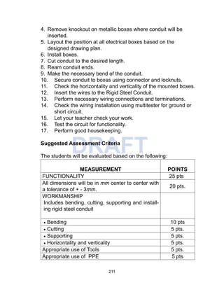
Figure 1: Show the schematic diagram of an appliance
without an equipment conductor connected to the metal chassis.
The appliance is sitting on a wood table, and therefore isolated
from earth ground. The appliance is “turned off”, but a wire
insulation fault has occurred before the switch. The chassis of
the appliance is at an electrical potential of 110 volts with respect
to ground. Since it is switched “off” and there is no path for fault
current to flow, no current flows in this circuit. Hence, the circuit
breaker will not trip, and the fault will go undetected.](https://image.slidesharecdn.com/electricalinstallationandmaintenancemodule10-190615094852-240724084137-2fe70a22/85/ELECTRICAL-INSTALLATION-AND-MAINTENANCE1-183-320.jpg)


![K-12 Module in TLE - ICT Grade 9 [All Gradings]](https://cdn.slidesharecdn.com/ss_thumbnails/k-12moduleintle-ictgrade9allgradings-150622124134-lva1-app6892-thumbnail.jpg?width=640&height=640&fit=bounds)


