C VENKATESH KUMAR
UNITIII - HEATING AND WELDING
Introduction - advantages of electric heating – modes of heat
transfer - methods of electric heating -resistance heating - arc
furnaces - induction heating - dielectric heating - electric welding
– types -resistance welding - arc welding - power supply for arc
welding - radiation welding.
3.
Domestic and industrialapplications of electric
heating.
Domestic applications include :
1. Room Heaters
2. Immersion Heaters For Water Heating
3. Hot Plates For Cooking
4. Electric Kettles
5. Electric Irons
6. Pop-corn Plants
7. Electric Ovens For Bakeries
8. Electric toasters etc.
Industrial applications of electric heating include:
9. Melting Of Metals
10. heat treatment of metals like annealing, tempering, soldering
and brazing etc.
3. Moulding Of Glass
4. Baking of insulators
5. Enamelling of copper wires etc.
4.
Advantages of electric
heating
1.This system is most clean system of heating. This is free
from dirt.
2. This electric heating process does not produce any flue gas.
3. This is much controlled method of heating.
4. Initial and running costs of electric furnaces are much lower
than other types of furnaces.
5. Automatic protection schemes for over loading and over
current can easily be provided in this system with help of
electrical switchgear system.
6. The overall efficiency of electric heating systemis
much more than other systems of heating.
7. There is no upper limit of producing temperature.
8. Electric heating is quite safe because it responds
quickly to the controlled signals.
5.
Modes / Methodsof Heat
Transfer
1.Conduction
In this mode of heat transfer, one molecule of the body
gets heated and transfers some of the heat to the
adjacent molecule and so on. There is a temperature
gradient between the two ends of the body being
heated.
2.Convection
In this process, heat is transferred by the flow of hot
and cold air. This process is applied in the heating of
water by immersion heater or heating of buildings.
3.Radiation
It is the transfer of heat from a hot body to a cold body
in a straight line without affecting the intervening
medium.
7.
PARTICULAR CONDUCTION CONVECTIONRADIATION
Meaning
Conduction is a
process in which
transfer of heat
takes place
between objects
by direct contact.
Convection refers
to the form of heat
transfer in which
energy transition
occurs within the
fluid.
Radiation is the
mechanism in which
heat is transmitted
without any physical
contact between
objects.
Represent
How heat travels
between objects
in direct contact.
How heat passes
through fluids.
How heat flows
through empty
spaces.
Cause
Due to
temperature
difference.
Due to density
difference.
Occurs from all
objects, at
temperature greater
than 0 K.
Differentiate between the methods of heat
transfer
8.
Occurrence
Occurs in
solids,
through
molecular
collisions.
Occurs influids,
by actual flow of
matter.
Occurs at a
distance and
does not heat
the intervening
substance.
Transfer of heat
Uses heated
solid
substance.
Uses
intermediate
substance.
Uses
electromagnetic
waves.
Speed Slow Slow Fast
Law of
reflection and
refraction
Does not
follow
Does not follow Follow
9.
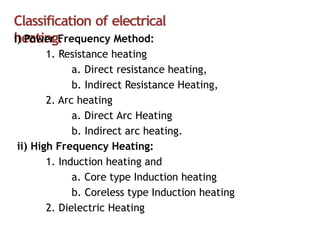
Classification of electrical
heating.
i)Power Frequency Method:
1. Resistance heating
a. Direct resistance heating,
b. Indirect Resistance Heating,
2. Arc heating
a. Direct Arc Heating
b. Indirect arc heating.
ii) High Frequency Heating:
1. Induction heating and
a. Core type Induction heating
b. Coreless type Induction heating
2. Dielectric Heating
10.
Resistance heating.
It isbased on the I2R effect.
When current is passed
through a resistance
element I2R loss takes place
which produces heat.
There are two methods of resistance heating.
1. Direct methods of resistance heating.
2. Indirect Resistance Heating.
In this methodthe material (or charge) to be heated is
treated as a resistance and current is passed through it. The
charge may be in the form of powder, small solid pieces or
liquid. The two electrodes are inserted in the charge and
connected to either a.c. or d.c. supply .
Two electrodes will be required in the case of d.c. or
single-phase a.c. supply but there would be three electrodes
in the case of 3-phase supply. When the charge is in the
form of small pieces, a powder of high resistivity material is
sprinkled over the surface of the charge to avoid direct short
circuit.
Heat is produced when current passes through it. This
method of heating has high efficiency because the heat is
produced in the charge itself.
13.
Applications of direct
heating
•This method of heating is used in
1. Resistance welding
2. The electrode boiler for heating
water
tool
s
3. Salt bath furnace which is used for
hardening steel and prevents oxidation
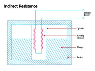
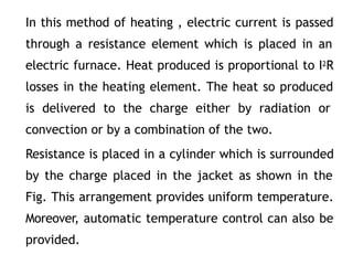
In this methodof heating , electric current is passed
through a resistance element which is placed in an
electric furnace. Heat produced is proportional to I2R
losses in the heating element. The heat so produced
is delivered to the charge either by radiation or
convection or by a combination of the two.
Resistance is placed in a cylinder which is surrounded
by the charge placed in the jacket as shown in the
Fig. This arrangement provides uniform temperature.
Moreover, automatic temperature control can also be
provided.
16.
Applications of indirect
heating
•This method of heating is used in
1. Room heaters
2. Water heater i.e. immersion
heater
3. Ovens like domestic cooking
17.
Requirement of goodheating
element.
• High-specific resistance
so that small length of wire may be required to provide given amount of heat.
• High-melting point
so that it can withstand for high temperature, a small increase in temperature
will not destroy the element.
• Low temperature coefficient of resistance
For accurate temperature control, the variation of resistance with the operating
temperature should be very low. Thiscan be obtained only if the material has
low temperature coefficient of resistance
• Free from oxidation
The formation of oxidized layers will shorten its life.
• High-mechanical strength
Should withstand for mechanical vibrations.
• Non-corrosive
The element should not corrode when exposed to atmosphere or any other
chemical fumes.
• Economical
The cost of material should not be so high
causes for failureof heating elements
1. Formation of Hot Spot
Hot spots are the points in the heating element which are formed at
higher temperature.
2. Contamination and Corrosion
Oil fumes caused by heat treatment of components contaminated with
lubricant contaminate the elements and produce dry corrosion.
3.Oxidation of the element and intermittency ofoperation.
4.Vibration Break
Excessive vibration may cause the heating element to break, resulting
to failure
20.
Temperature control methodsof resistance
furnace
The temperature of a resistance furnace can
be changed by controlling the I2R or V2/R losses.
1. Intermittent Switching.
2. By Changing the Number of Heating Elements
3. Variation in Circuit Configuration.
4. Change of Applied Voltage.
(a)Lesser the magnitude of the voltage applied to the load.
(b)Bucking-Boosting the Secondary Voltage
(c)Autotransformer Control.
(d)Series Reactor Voltage.
21.
(1)Intermittent Switching.
In thiscase, the furnace voltage is switched ON
and OFF intermittently. Hence, by this simple
method, the furnace temperature can be limited
between two limits.
(2)By Changing the Number of Heating Elements.
In this case, the number of heating elements is
changed without cutting off the supply to the
entire furnace. Smaller the number of heating
elements, lesser the heat produced . In the case of
a 3-phase circuit, equal number of heating
elements is switched off from each phase in order
to maintain a balanced load condition.
22.
(3) Variation inCircuit
Configuration.
In the case of 3-phase secondary load, the heating elements
give less heat when connected in a star than when connected
in delta because in the two cases, voltages across the elements
is different (Fig. 1). In single-phase circuits, series and parallel
grouping of the heating elements causes change in power
dissipation resulting in change of furnace temperature.
23.
As shown inFig.1 heat produced is more when all
these elements are connected in parallel than when
they are connected in series or series-parallel.
24.
Change of Applied
Voltage.
Lesserthe magnitude of the voltage applied to the load, lesser the
power dissipated and hence, lesser the temperature produced. In
the case of a furnace transformer having high voltage primary, the
tapping control is kept in the primary winding because the
magnitude of the primary current is less. Consider the multi-tap
step-down transformer shown in Fig.
25.
Autotransformer
Control.
Fig. shows theuse of tapped autotransformer used for
decreasing the furnace voltage and, hence, temperature of
small electric furnaces. The required voltage can be
selected with the help of a voltage selector.
26.
Arc
Furnace
If a sufficientlyhigh voltage is applied across an
air-gap, the air becomes ionized and starts
conducting in the form of a continuous spark or
arc thereby producing intense heat. When
electrodes are made of carbon/graphite, the
temperature obtained is in the range of 3000°C-
3500°C. The high voltage required for striking the
arc can be obtained by using a step-up
transformer fed from a variable a.c. supply as
shown in
Fig. (a).An arccan also be obtained by using low
voltage across two electrodes initially in contact
with each other as shown in Fig. (b). The low
voltage required for this purpose can be obtained
by using a step-down transformer. Initially, the low
voltage is applied, when the two electrodes are
in contact with each other. Next, when the two
electrodes are gradually separated from each
other, an arc is established between the two.
• Inthiscase,arc isformed between the
two
electrodes and the charge in such a way that electric
current passes through the body of the charge as
shown in Fig. Such furnaces produce very high
temperatures.
• It could be either of conducting-bottom type Fig. (a)
or non-conducting bottom type Fig. (b) .
• As seen from Fig. (a), bottom of the furnace forms
part of the electric circuit so that current passes
through the body of the charge which offers very
low resistance. Hence, it is possible to obtain high
temperatures in such furnaces. Moreover, it
produces uniform heating of charge without stirring
it mechanically.
• In Fig. (b), no current passes through the body of
the furnace.
31.
• Applications
These furnacesis in the production of
steel
composition of the final product
can
because of the ease with which the
be
controlled during refining. Most of the
furnaces in general use are of non-conducting
bottom type due to insulation problem faced
in case of conducting bottom.
Fig. shows asingle-phase indirect arc furnace
which is cylindrical in shape. The arc is struck
by short circuiting the electrodes manually or
automatically for a moment and then ,
withdrawing them apart. The heat from the
arc and the hot refractory lining is transferred
to the top layer of the charge by radiation.
The heat from the hot top layer of the charge
is further transferred to other parts of the
charge by conduction.
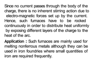
34.
Since no currentpasses through the body of the
charge, there is no inherent stirring action due to
electro-magnetic forces set up by the current.
Hence, such furnaces have to be rocked
continuously in order to distribute heat uniformly
by exposing different layers of the charge to the
heat of the arc.
Application : Such furnaces are mainly used for
melting nonferrous metals although they can be
used in iron foundries where small quantities of
iron are required frequently.
35.
Induction
Heating
This heating processmakes use of the currents
induced by the electro-magnetic action in the charge
to be heated. In fact, induction heating is based on
the principle of transformer working. The primary
winding which is supplied from an a.c. source is
magnetically coupled to the charge which acts as a
short circuited secondary of single turn.
heat produced = V 2/R.
The value of current induced in the charge depends
on-
(i ) Magnitude Of The Primary Current
(ii) Turn ratio of the transformer.
(iii) Co-efficient of magnetic coupling.
36.
Types of Induction
Heating
(a)Core-type Furnaces -
which operate just like a two winding
transformer.
These can be further sub-divided into
(i)Direct core-type furnaces
(ii)Vertical core-type furnaces and
(iii)Indirect core-type furnaces.
(b) Coreless-type Furnaces- In which an inductively-
heated element is made to transfer heat to the charge
by radiation.
• It isshown in Fig.. and is essentially a transformer in
which the charge to be heated forms a single-turn
short-circuited secondary and is magnetically coupled
to the primary by an iron core. The furnace consists
of a circular hearth which contains the charge to be
melted in the form of an annular ring.
• When there is no molten metal in the ring, the
secondary becomes open-circuited there-by cutting
off the secondary current. Hence, to start the
furnace, molted metal has to be poured in the
annular hearth.
• Since, magnetic coupling between the primary and
secondary is very poor, it results in high leakage and
low power factor. In order to nullify the effect of
increased leakage reactance, low primary frequency
of the order of 10 Hz is used.
39.
Advantages of DirectCore Type Induction
Furnace
1. Rapid melting.
2. Accurate control of the temperature.
3. Clean heating.
4. The furnace inherently has stirring action of
the molten material and this result in
uniform end material.
40.
Disadvantages Of DirectCore Type Induction
Furnace
1. Pinch effect – at high current densities the
current flowing through the melt will interact
with magnetic field of the core.
2. The furnace cannot be started with a solid
material as it may open circuit the
3. The furnace is not suitable for intermittent
operation.
41.
Application
s
1. Used infoundries for melting and
refining brass, zinc and other non-
ferrous metals
2. Used for heat treatment of metals
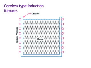
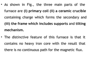
• As shownin Fig., the three main parts of the
furnace are (i) primary coil (ii) a ceramic crucible
containing charge which forms the secondary and
(iii) the frame which includes supports and tilting
mechanism.
• The distinctive feature of this furnace is that it
contains no heavy iron core with the result that
there is no continuous path for the magnetic flux.
44.
• The
crucible
construction
and thecoil are
relatively light in and can
be conveniently tilted for
pouring. The charge is put into the crucible and
primary winding is connected to a high-frequency
a.c. supply. The flux produce by the primary sets up
eddy- currents in the charge and heats it up to the
melting point.
• The charge need not be in the molten state at the
start as was required by core-type furnaces. The
eddy- currents also set up electromotive forces
which produce stirring action which is essential for
obtaining uniforms quality of metal. Since flux
density is low (due to the absence of the magnetic
core) high frequency supply has to be used because
eddy- current loss We∝ B2f 2.
45.
• Since magneticcoupling between the primary
and secondary windings is low, the furnace
p.f. lies between 0.1 and 0.3. Hence, static
capacitors are invariably used in parallel with
the furnace to improve its p.f.
46.
Advantages of corelessinduction furnaces are as
follows :
1. High speed of
heating
2. Well suited for intermittent operation
3. High quality of product
4. Low operating cost
5. They produce most uniform quality of product.
6. Their operation is free from smoke, dirt, dust
and noises.
7. They
can
be used for all industrial
applications
requiring heating and melting.
8. They have low erection and operating
costs.
9. Their charging and pouring is simple.
47.
Applications
.
1. These areused for steel production
2. These are used for melting of non-ferrous
metals like brass , copper, aluminium along
with various alloys of these elements
3. The production of carbon from ferrous alloys
48.
High frequency eddycurrent
heating.
For heating an article by eddy-currents, it is placed inside a high
frequency a.c. current-carrying coil.
it is the eddy-current loss which is responsible for the production of
heat through hysteresis loss also contributes to some extent in the
case of non-magnetic materials. The eddy-current loss We ∝ B2 ƒ2.
Hence, this loss can be controlled by controlling flux density B and
the supply frequency ƒ. This loss is greatest on the surface of the
material but decreases as we go deep inside.
49.
The depth ofthe material upto which the eddy-
current loss penetrates is given by-
50.
Advantages of Eddy-currentHeating
(1)There is negligible wastage of heat because
the heat is produced in the body to be heated.
(2)It can take place in vacuum or other special
environs where other types of heating are not
possible.
(3)Heat can be made to penetrate any depth of
the body by selecting proper supply frequently.
51.
Applications of eddycurrent
heating.
1. Surface Hardening. The bar whose surface is to
be hardened by heat treatment is placed within
the working coil which is connected to an a.c.
supply of high frequency.
2. Annealing. Normally, annealing process takes long
time resulting in scaling of the metal which is
undesirable. However, in eddy-current heating,
time taken is much lessso that no scale formation
takes place.
3. Soldering. Eddy-current heating is economical for
precise high-temperature soldering where silver,
copper and their alloys are used as solders.
52.
• Di-electric
heating
It isalso called high-frequency capacitative heating
and
is used for heating insulators like wood, plastics and
ceramics etc. which cannot be heated easily and
uniformly by other methods. The supply frequency
required for dielectric heating is between 10-50 MHz
and the applied voltage is upto 20 kV. The overall
efficiency of dielectric heating is about 50%.
53.
• When apractical capacitor is connected across an
a.c. supply, it draws a current which leads the
voltage by an angle φ, which is a little less than 90°
or falls short of 90° by an angle δ. It means that
there is a certain component of the current which is
in phase with the voltage and hence produces some
loss called dielectric loss. At the normal supply
frequency of 50 Hz, this loss is negligibly small but at
higher frequencies of 50 MHz or so, this loss
becomes so large that it is sufficient to heat the
dielectric in which it takes place. The insulating
material to be heated is placed between two
conducting plates in order to form a parallel-plate
capacitor as shown in Fig
54.
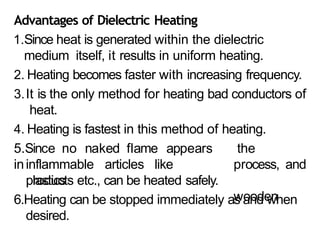
Advantages of DielectricHeating
1.Since heat is generated within the dielectric
medium itself, it results in uniform heating.
2. Heating becomes faster with increasing frequency.
3.It is the only method for heating bad conductors of
heat.
4. Heating is fastest in this method of heating.
5.Since no naked flame appears
ininflammable articles like
plastics
the
process, and
wooden
products etc., can be heated safely.
6.Heating can be stopped immediately as and when
desired.
55.
Principle of microwave
heating.
Microwaveheating is a multi-physics phenomenon that
involves electromagnetic waves and heat transfer; any
material that is exposed to electromagnetic radiation
will be heated up. The rapidly varying electric and
magnetic fields lead to four sources of heating.
Any electric field applied to a conductive material will
cause current to flow. In addition, a time-varying electric
field will cause dipolar molecules, such as water, to
oscillate back and forth. A time-varying magnetic field
applied to a conductive material will also induce current
flow. There can also be hysteresis losses in certain types
of magnetic materials.
56.
Applications of Microwave
Heating
1.Heating Food
One obvious example of microwave heating is in a
microwave oven. When you place food in a microwave
oven and press the "start" button, electromagnetic
waves oscillate within the oven at a frequency of 2.45
GHz. These fields interact with the food, leading to
heat generation and a rise in temperature.
2. Treating Cancer
Another application that leverages the effects of
microwave heating is cancer treatment, in particular
hyperthermic oncology. This type of cancer therapy
involves subjecting tumor tissue to localized heating,
without damaging the healthy tissue around it.
57.
Definition of
Welding
It isthe process of joining two pieces of
metal or non-metal at faces rendered
plastic or liquid by the application of heat
or pressure or both. Filler material may be
used to effect the union.
58.
Welding
Processes
All welding processesfall into two distinct categories :
1. Fusion Welding- It involves melting of the parent metal. Examples are:
• Carbon arc welding, metal arc welding, electron beam welding, electro slag
welding and electro-gas welding which utilize electric energy and
• Gas welding and thermit welding which utilize chemical energy for the melting
purpose.
2. Non-fusion Welding- It does not involve melting of the parent metal. Examples
are:
• Forge welding and gas non-fusion welding which use chemical energy.
• Explosive welding, friction welding and ultrasonic welding etc., which
use mechanical energy.
• Resistance welding which uses electrical energy.
Proper selection of the welding process depends on the (a) kind of metals to
be joined (b) cost involved (c) nature of products to be fabricated and (d)
production techniques adopted
59.
Types of electricwelding.
1. Resistance welding
a) Seam welding
b) Projection welding
c) Flash welding.
d) spot welding
2. Arc welding
e)Carbon arc welding
f) Metal arc welding
g) Atomic hydrogen arc welding
h) Inert gas metal arc welding
i) Submerged arc welding.
The process dependson two factors :
1.Resistance heating of small portions of the two
work pieces to plastic state and
2.Application of forging pressure for welding
the two work pieces.
Heat produced is H = I2 Rt/J. The resistance R is
made up of (i) resistance of the electrodes and
metals themselves (ii) contact resistance between
electrodes and work pieces and (iii) contact
resistance between the two work pieces.
Generally ,contact resistance between the two
work pieces is the greatest.
63.
As shown inFig (b), mechanical pressure is
applied by the tips of the two electrodes. In
fact, these electrodes not only provide the
forging pressure but also carry the welding
current and concentrate the welding heat on
the weld spot directly below them. Fig. (a)
shows diagrammatically the basic parts of a
modern spot welding. It consists of a step-
down transformer which can supply huge
currents (upto 5,000 A) for short duration of
time. The metals under the pressure zone get
heated upto about 950°C and fuse together
64.
Application:
Spot welding isused for galvanized, tinned
and lead coated sheets and mild steel sheet
work. This technique is also applied to non-
ferrous materials such as brass, aluminium,
nickel and bronze etc.
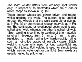
The seam welderdiffers from ordinary spot welder
only in respect of its electrodes which are of disc or
roller shape as shown in Fig. (a).
These copper wheels are power driven and rotate
whilst gripping the work. The current is so applied
through the wheels that the weld spots either overlap
as in Fig. (b) or are made at regular intervals as in Fig.
(c). The continuous or overlapped seam weld is also
called stitch weld whereas the other is called roll weld.
Seam welding is confined to welding of thin materials
ranging in thickness from 2 mm to 5 mm. It is also
restricted to metals having low harden-ability rating
such as hot-rolled grades of low-alloy steels. Stitch
welding is commonly used for long water-tight and
gas- tight joints. Roll welding is used for simple joints
which are not water-tight or gas-tight. Seam welds are
usually tested by pillow test.
Welding is neverdone directly from the supply mains.
Instead, special welding machines are used which
provided currents of various characteristics. Use of such
machines is essential for the following reasons :
T
o reduce the high supply voltage to a safer and
suitable voltage for welding purposes.
T
o provide high current necessary for arc welding
without drawing a corresponding high current from the
supply mains.
T
o provide suitable voltage/current relationships
necessary for arc welding at minimum.
As shown in Fig. it consists of a step-down transformer
with a tapped secondary having an adjustable reactor
in series with it for obtaining drooping V/I
characteristics. The secondary is tapped to give
different voltage/ current settings.
70.
Advantages of ARCwelding
1. Low initial cost
2. Low operation and maintenance cost
3. Low wear
4. No arc blow
Disadvantages ARC welding .
5. its polarity cannot be changed
6. it is not suitable for welding of cast iron and
non-ferrous metals.
• It usesan extremely concentrated beam of
coherent monochromatic light i.e. light of only
one colour (or wavelength). It concentrates
tremendous amount of energy on a very small
area of the workpiece to produce fusion. It
uses solid laser (ruby, saphire), gas laser (CO2)
and semiconductor laser. Both the gas laser
and solid laser need capacitor storage to store
energy for later injection into the flash tube
which produces the required laser beam.
73.
• The gaslaser welding equipment consists of
(i)capacitor bank for energy storage (ii) a
triggering device (iii) a flash tube that is
wrapped with wire (iv) lasing material (v)
focusing lens and (vi) a worktable that can
rotate in the three X, Y and Z directions.
When triggered, the capacitor bank supplies
electrical energy to the flash tube through
the wire. This energy is then converted into
short- duration beam of laser light which is
pin- pointed on the work-piece as shown in
Fig.. Fusion takes place immediately and
weld is completed fast.
74.
Since duration oflaser weld beam is very
short (2 ms or so), two basic welding
methods have been adopted. In the first
method, the work piece is moved so fast that
the entire joint is welded in a single burst of
the light. The other method uses a number of
pulses one after the other to form the weld
joint similar to that formed in electric
resistance seam welding.
75.
Advantages of laser
welding
1.It produces high weld quality.
2. it can be easily automated with robotic machinery for
large volume production.
3. No electrode is required.
4. No tool wears because it is a non-contact process.
5. The time taken for welding thick section is reduced.
6. It is capable of welding in those areas which is not
easily accessible.
7. It has the ability to weld metals with dissimilar
physical properties.
8. It can be weld through air and no vacuum is required.
9. It can be focused on small areas for welding. This is
because of its narrower beam of high energy.
10. Wide variety of materials can be welded by using laser
beam welding.
76.
Disadvantages of laserwelding.
1. Rapid cooling rate may cause cracking in some metals
2. High capital cost for equipment
3. Optical surfaces of the laser are easily damaged
4. High maintenance costs
5. Energy conversion efficiency is too low, usually below 10%.
6. laser welding machine is expensive.
7. Max welding thickness is 19mm, and it isn’t suitable for production
line.
Applications of laser welding
Laser welding is used in the Automotive, aircraft and
electronic
industries for lighter gauge metals