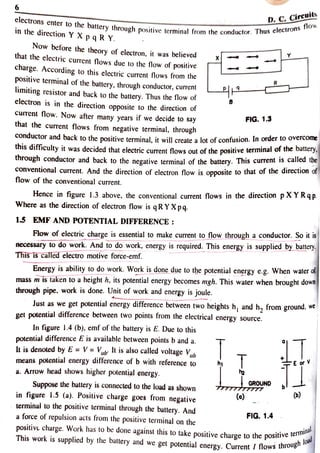
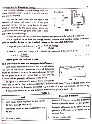
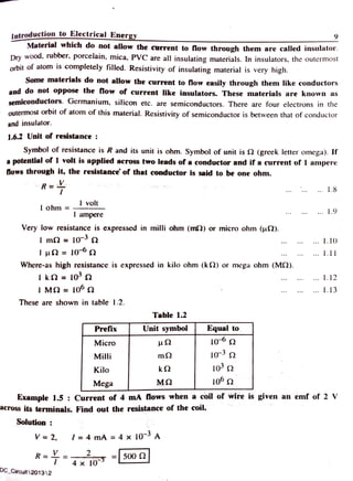
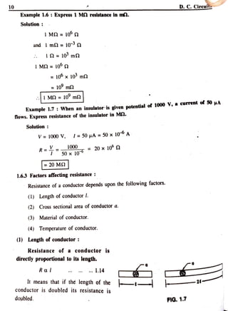
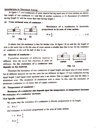
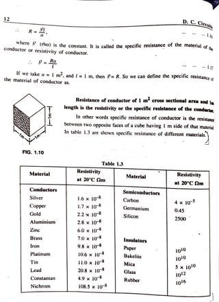
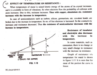
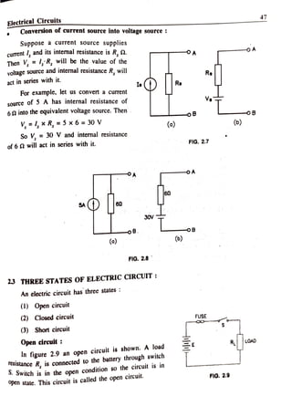
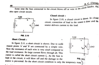
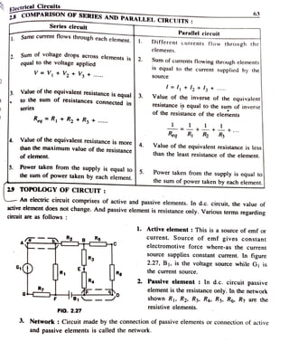
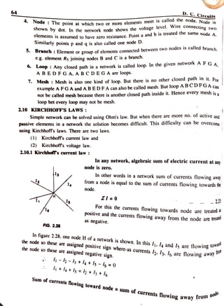
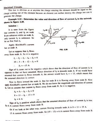
Energy is available in various forms like, mechanical, chemical, heat, electrical etc. Amon
all these electrical energy is widely used. This is because it can be produced in bulk, can b
transmitted from one place to another through electrical conductor and can be converted int
other fom like heat, light, mechanical etc. In this unit, we shall study the basic concepts like
1.1 INTRODUCTION:
charge, current, emf resistance, work power, etc.
1.2 ELECTRICCHARGE:
When a rod of abonite is rubbed with woolen clothe or a
glass rod is rubbed with silk
clothe, small pieces of paper, dust particals, dry leaves are attracted to the end of the rod, This
is because electric charge is produced at the end of the rod. Thus when two different materials
are rubbed with each other electric charge is produced.
Electric charge is of two types (1) Positive electric charge and (2) Negative
electric charge
Symbol of electric charge is Q or q. Its unit is coulomb and its symbol is
C.
1.3 ATOM AND ITSSTRUCTUREE
All matter comprise of the fundamental particles known as atoms. Acco.
model, an atom has a central core called the nucleus, which contain parotons an8 to Bohr's
protons are positively charged particles and the neutrons have no
charge. So th
ng to Bohr's
utrons. The
narge of the
orbits
elliptical in
shape.
nucleus is positive. Electrons revolve round the nucleus in different orbits ell:.
The charge of electron is negative.
3
Introduction toElectrical Energy
Diameter of atom is in the order of 10-1 m where -as that of nucleus is in the order of
10 m. Electrons are light particles. Protons and neutrons are heavy particles. These are about
1837 times heavier than electrons. Hence mass of an atom is mainly due to the mass of protons
and neutrons.
Protons, neutrons and electrons are the NUCLEUS
fundamental particles. Protons of all the elements are
identical and so also the electrons and the neutrons.
For example, protons of copper and gold are identical
The neutrons and the electrons of these two elements
ELECTRONS
are also identical, eventhough the physical and thee
chemical properties of these elements are quite
different. This is because the number of protons,
- ELLIPTICAL
ORBIT
+PROTONSs
n NEUTRONS
neutrons and electrons and their arrangement in
different elements are different. However all the atoms
FIG. 1.1
of a particular element are identical.
In any element. the number of protons and electorns are equal. This number is called the
atomic number and is denoted by letter Z. The sum of number of protons and neutrons is called
the atomic mass number and is represented by symbol A. Hence A- Z = number of neutrons.
The element is represented by its symbol, with the atomic number and the atomic mass nunmber
16
as 7 (Symbol of the element). For example oxygen is represented byO. carbon byC
copper by 9 Cu etc. Since the number of protons and electrons in an atom are equal, the net
charge of an atom is zero. So an atom is electrically neutral
All the electrons in an atom revolve round the nucleus in different orbits rather in a single
orbit. The maximum number of electrons in a particular orbit is fixed. It is given by the relation
2n, where n is the number of the orbit. So the first orbit near to the nucleus can accomodate
maximum of 2(1)? =2 electrons. Then the second orbit can accomodate maximum of 2(2)2 = 8
electrons. This way the maximum number of electrons in successive orbits will be 2. 8, 18, 32..
respectively. However the outermost orbit can not accomodate more than 8 electrons. The electrons
in the outermost orbit are called the valence electrons.
1.3.1 Charge and mass of electron :
Charge of an electron is l.602 x 10-1 coulomb and its symbol is q. Its mass is
9.108 x 10⁻³¹ kg. and its symbol is m.
Ratio ofcharge to mass is called the q/m ratio and for electron its value is 1.750 x 10' Clkg.
Ratio of mass of proton to that of electron is 1.837 x 10³.
4
D.C. Circuits
1.3.2 Bound and free electrons
We leamt that the ealectrons revolve round the nucleus in various orbits.
accomodate.
orbit
nearest to the nucleus is filled with the maximum number of electrons which it can
i t c a n a c c o m o d a t e .
Then the further orbits are filled in turn. So depending upon the number of
electro ac in
atom,
the
the outermost orbit may be filled completely or may remain incomplete. The
ns in
electrons
the outermost
"
inner complete shells or orbits are called the bound electrons and the electrons
in
mnlet
incomplete shell are called the free electrons, These free electrons in the outermost inco
Snell are called the free electrons. These free electrons are called the valence elecron
C ciectrons or valance electrons take part in the chemical reaction and in the conducuon or
current, where-as bound electrons can not do so.
The charge of electron is negative and that of nucleus is positive. So electrons are
continuously attracted towards nucleus. This force according to Coulomb's law is inversly
proportional to the square ofthe distance. So this force is less for the electrons in the outer shell
compared to that in the inner shell. Hence valence electrons experience lesser force of attraction
compared to the bound electrons.
14 ELECTRICCURRENT
When there are less than four electrons in the outermost orbit of atom, these electrons are
called the free electrons. In metal such an arrangement exists. When electric potential is applied
across the two ends of a conductor, these free electrons move from one end to the other. Electron
has electric charge. So charge move from one end to the other. Flow of these electrons or
charge is called electric current.
Current/ A .. 1.I
Unit of charge is coulomb. When charge of 1 coulomb passes through a point in !
second, it is said that a current of I ampere is lowing.
Ampere =Coulomb
Second
A
Thus charge flowing per second through cross section of a conductor is electric curren
And when a charge I is coulomb is flowing per second, the current is said to be 1 ampere
current is constant, the charge is transferred at the constant rate, and
If
Q I xi
But when the value of current is not constant and is changing continuously,
1.2
i= A4
Ar . 1.3
where A is charge transterred in very small time At.
Introductionto ElectricalEnergy_
Ag
lim
i= dq
dt
1 . 4
*
Example 1.1: Charge of 60 coulomb nows in 15 second through the cross section of a
conductor, what is the value of current nowing ?
Solution
1.4.1 Current flow and number of electrons
One coulomb per second means 1 ampere of current.
Now charage of electron is 1.602 x 10- C. So one coulomb =
1.602 x 101
= 6.242 x
10 electron.
Hence when a current of
ampere flows through a conductor
6.242 x 10⁸ electrons are flowing
through its cross sections.
Electric be
(o) PLOW OF ELECTRONS (6) FLOW OF WATER
current can
compared with the flow of water
through a pipe. Just as water flows
through the pipe, electrons flow through the conducto.
FIG. 1.2
Example 1.2 Current of15 A lows through a conductor. How many numbers of
electrons are flowing in one second through the cross section ?
Solution
15 ampere =15 oulomb
sec
= 15 x 6.242 x 108 electron/sec.
= 93.63 x 10⁸ electron/sec.
14.2 Conventional current and direction of electron flow
In figure 1.3, a conductor XY is connected across terminals p and q of a bettery B. R is
the resistance connected to limit the current.
When battery B is connected as shown, the electrons in the conductor are attracted towardss
the positive terminal of the battery as the charge of electrons is negative. That many number of
electrons enter the conductor from the negative terminal of the battery as that many number of
6 D. C. Circuits
ns flow
eIectrons enter to the battery through positive terminal from the conductor. nus
in the direction Y X p qR Y.
Now before the theory of electron, it was believed
that the electric current flows due to the flow of positive
charge. According to this electric current flows from the
positive terminal of the battery, through conductor, current
limiting resistor and back to the battery. Thus the flow of
electron is in the direction opposite to the direction of
curent flow. Now after many years if we decide to say
that the current flows from negative terminal, through
FIG. 1.3
OTctor and back to the positive terminal, it will create a lot of confusion. In order to overcome
this difficulty it was decided that electric current flows out of the positive terminal of thebattery
tnrough conductor and back to the negative terminal of the battery. This current is called the
conventional current. And the direction of electron flow is opposite to that of the direction of
flow of the conventional current.
Hence in figure 1.3 above, the conventional current flows in the direction pXYRqp
Where as the direction of electron flow is qRYXpq
1.5 EMF AND POTENTIAL DIFFERENCE
Flow of electric charge is essential to make current to flow through a conductor. So it is
necessary to do work. And to do work, energy, is required. This energy is supplied bybattery.
This is calledelectro motive force-emf.
Energy is ability to do work. Work is done due to the potential energy e.g. When water of
mass m is taken to a height h, its potential energy becomes mgh. This water when brought down
through pipe, work is done. Unit of work and energy is joule.
Just as we get potential energy difference between two heights h, and h, from ground, we
get potential difference between two points from the electrical energy source.
In figure 1.4 (b), emf of the battery is E. Due to this
potential difference E is available between points b and a.
It is denoted by E = V= Vab lt is also called voltage Vah
means potential energy difference of b with reference to
a. Arrow head shows higher potential energy.
T
E or V
Suppose the battery is connected to the load as shown
in figure 1.5 (a). Positive charge goes from negative
terminal to the positive terminal through the battery. And
a force of repulsion acts from the positive terminal on the
positive charge. Work has to be done against this to take positive charge to the positive d
GROUND
(o) (b)
FIG. 1.4
This work is supplied by the battery and we get potential energy. Current I flows throu
erminak
l o a d
Introductlon to Electrical Energy
which flows from higher potential energy level a to
lower potential encrgy level b. It is said that the
TANK
potential is dropped.
This can be understood with the help of the
LOAD
exumple of pump und water tank. Water gets
potential energy. For this work has to be done
which is supplied by the pump motor. When this
water comes down through pipe, then work is done
due to the potential energy.
PUMP
(o) (b)
FIG. 1.5
Voltage or potential energy difference between two points can be defined as follows.
Work requlred to be done (or energy needed) to move unit positive charge from one
polnt to another In the circuit is called voltage or the potential difference.
Voltuge or potential difference . Work orEnergy 1.5
Charge
If
work is I joule and charge is I coulomb, then potential difference is volt.
volt= JOule
I coulomb
. 1.6
Hence Joule per coulomb is volt.
1.5.1 Diterence between emf and potential difference:
emf means electromotive force due to which charge
can flow in the circuit. Where-as potential difference
means the difference between the potential energy between
the two points in a circuit. Unit of both are volt. But emf
is cause and the potential difference is the effect.
In figure 1.6, current of / ampere flows through the
circuit due to emf E. Due to this current flow. potential difference Vab is produced across two
terminals of resistor R1. Potential difference Ved is produced across two terminals of resistor R2.
Comparison between emf and potential difference is given in table l.1.
R R2
FIG. 1.6
Table 1.1
Potential difference
emf
|. emf means force required for the current . Potential difference means thedifference
to flow through the circuit.
between potential energy of two points
emf is the cause because curent flows due 2. Potential difference is the effect because
potential difference is produced due to
2.
to emf
current flow.
3. Its unit is also volt.
Its unit is volt.
8
1.5.2 Absolutepotential:
Force on a charge situated at infinite distance in an electric field is zero. So the infinie
distance is treated as zero potential. Absolute potential can be defined as follows :
D. C. Circuits
In electric field, work required to be done in bringing a charge of 1 coulomb from inimy
to a point is called the potential of that point.
t charge is 1 coulomb and work required to be done is 1 joule, then the potential o
that point is 1 volt.
1 joule
volt 1 coulomb
. 7
Example 13 : Work of 300 joule has to be done to bring a charge of 5 coulomb from
infinity to point a in an electric field. Find the potential of point a.
Solution
Potential =Workdone
Charge
=60 volt
Example 1.4: Electric potential ofa point is 100 volt. What work is required to be
done to bring a charge of 4 coulomb from infinity to that point ?
Solution:
Potential = Workdone
Charge
100= Work done
Work done = 100 x 4 =|400 joule
16 RESISTANCE:
Property of a material to oppose the flow of electric current through it is called resistance
We studied that when a conductor is given emf, electric current flows due to the flow of fiee
electrons. When these electrons move, they collide with the atoms. So flow of electric curren
opposed. Due to this collison, some kinetic energy is converted in to heat energy. Cyou
structures of different materials are different. So all materials do not oppose the flow Or c
current equally. That means resistance of different material is different.
Ystalline
1.6.1 Conductor, insulator and semiconductor:
Materials wlhich allow the current to low easily through them are called
ue
Metals are good conductors of current. In this also, silver, copper and alu
conductors. Metal, salt solutions, acids also are good conductors. In atomOr
are less than four electrons in the outermost orbit. Resistivity of conducto
l e d t h e c o n d u c t o r
aregow
/ sthere
Conductorsthee
is low
Introductionto Electrical Energy
Material which do not allow the current to flow through them are called insulator.
Dry wood, rubber, porcelain, mica, PVC are all insulating materials. In insulators, the outermost
orbit of atom is completely filled. Resistivity of insulating material is very high.
9
Some materials do not allow the current to fow easily through them like conductors
and do not oppose the flow of current like insulators. These materials are known asS
semiconductors. Germanium, silicon etc. are semiconductors. There are four electrons in the
outermost orbit of atom of this material. Resistivity of semiconductor is between that of conductor
and insulator.
1.6.2 Unit of resistance
Symbol of resistance is R and its unit is ohm. Symbol of unit is 2 (greek letter omega). If
a potential of I volt is applied across two leads of a conductor and if a current of 1 anmpere
fows through it, the resistance' of that conductor is said to be one ohm.
R 1 . 8
I volt
I ohm = 1.9
ampere
Very low resistance is expressed in milli ohm (mi2) or micro ohm (u2).
I m2 =10- n
I uN = 100 n
.. 1.10
1.11
Where-as high resistance is expressed in kilo ohm (k2) or mega ohm (M2).
IkN = 10 n 1 1 2
I MN = l0° Q 1.13
These are shown in table 1.2.
Table 1.2
Prefix Unit symbol Equal to
Micro 102
Milli m2
Kilo 10 Q
Mega M2
Example 1.5: Current of 4 mA lows when a coil of wire is given an emf of 2 V
across its terminals. Find out the resistance of the coil.
Solution
V 2, l= 4 mA =4 x 10 A
R 4x10 -500
DC_Circuit1201312
10 D. C. Circuít
Example 1.6 : Express 1 MQ resistance in ma.
Solution
I MQ = 10 n
and I m2 = 10 Q
19= 10 mQ
I MQ = 10° n
= 10 x 10 m2
1 0 m2
I MQ =10 m2
Example 1.7: When an insulatoris given potential of 1000 V, a current of 50 uA
Nows. Express resistance of the insulator in M9.
Solution
V 1000 V, I=50 uA = 50 x 10 A
R
1000 = 20 x 10° 2
50 x 100
20 M2
1.6.3 Factorsaffecting resistance:
Resistance of a conductor depends upon the following factors.
(1) Length of conductor .
(2) Cross sectional area of conductor a.
(3) Material of conductor.
(4) Temperature of conductor.
(1) Length of conductor:
Resistance of a conductor is
directly proportional to its length.
C
Ral .. 1.14
It means that if the length of the
conductor is doubled its resistance is
-2
doubled. FIG. 1.7
Introductionto Electrical Energy 11
In figure 1.7, two conductors of same material having equal area of cross section are shown.
But length of one conductor is l and that of another conductor is 21. Resistance of conductor
having length 2/ wil be twice than that having length .
(2) Cross sectional area of conductor:
20 Resistance of a conductor is inversely
proportional to its area of cross section.
Ra 1.15
(o) (b)
FIG. 1.8
It means that the resistance is less for thicker wire. In figure 1.8 (a) and (b), the length of
wire is the same but in (b) the area of cross section is double than that in (a). So the resistance
of conductor in (b) will be half of that in (a).
(3) Material of conductor:
Crystalline structure of different material is
different. Also the no.of free electrons in atom are
-t-
cOPPER ALUMINIUM
different. So the resistance of a conductor also
FIG. 1.9
depends on the material.
Therefore the hesistance of two conductors of equal length and equal area of cross section
but of different material are not the same but are different. In figure 1.9 two conductors having
equal length 7 and equal cross sectional area a are shown. One is copper wire and the other is
aluminium wire. The resistance of aluminium wire is more. In this case the resistance of
aluminium conductor is 1.6 times that of copper conductor.
(4) Temperature ofconductor:
Resistance of a conductor also depends upon the temperature. As temperature increases
the resisiance of a conductor increases.
1.6.4 Specific resistance:
We learnt that the resistance of a conductor is directly proportional to its length.
i.e. R oal
and resistance is in versely proportional to the area of cross section.
i. e. Ra
R a L
a
D. C. Cireuitt
12
R
..16
where S (rho) is the constant. It is called the specific resistance of the materiai ofth
rial of the
conductor or
resistivity of conductor.
9 =
17
It we take a = 1 m, and = 1 m, then S= R. So we can define the specitic resistanceof
the material of conductor as.
Resistance of conductor of 1 m cross sectional area and Im
length is the resistivity or the specific resistance of the conductor
In other words specific resistance of conductor is the resistance
between two opposite faces of a cube having I m side of that material.
In table 1.3 are shown specific resistance of different materials.
Im - 1 m
FIG. 1.10
Table 1.3
Resistivity Resistivity
Material
Material
at 20°C Qm
at 20°C Qm
Conductors
Semiconductors
Silver 1.6 x 10 Carbon 4x 10⁵
Copper 1.7 x 10⁻⁸
Germanium 0.45
Gold 2.2 x 10⁻⁸ Silicon 2500
Aluminium 2.8 x 10⁸
Zinc 6.0x 10⁻⁸
Brass 7.0x 10⁻⁸ Insulators
Iron 9.8 x 10⁻⁸
Paper 1o10
Platinumn 10.6 x 10⁻⁸ Bakelite
Tin T1.0 x 10-8 Mica Sx 1010
Lead 20.8x 10⁻⁸ Glass
4.9x 10⁸ Rubber 1ol6
Constantan
Nichrom 108.5x 10⁻⁸
1.7 EFFECT OFTEMPERATURE ON RESISTANCE:
When temperature of metal is raised kinetic energy of the atoms of its crystal increases.
and it is available in form of vibrations. So when electrons flow the probability of collision with
atom increases. Due to this, resistane increases. Thus with copper, aluminium etc. resistance
increases with the increase in temperature.
In case of semiconductors such as carbon, silicon, germanium, etc. covalent bonds are
broken due to the increase in temperature. So no. of free electrons is increased. So the conductivity
increases and resistance decreases. Thus the resistance of semiconductor decreases with the
increase in temperature.
Resistance of insulator
.17
and electrolyte also decreases
with the increase in
temperature.
In some materials, such as
R
constantan, there is no change or
Ro very small change in resistance
with the increase in resistance.
-273C D O t1 A
Graph of resistance v/s
temperature for metal is shown
in figure 1.13. lt is seen that for
most of the portion the curve is
ABSOLUTE INFERED
ERO
EMP
TEMPERATURE 'C-
ZERO
(-234.5C FOR COPPER)
FIG. 1.13
linear.
DC_Circuit 201313
D.
At absolute zero temperature (-273° C or 0 K), resistance of any metal become
When linear curve is extended up to x- axis, itcuts at point D. This iscalled
o m e s
the
z e r o .
nfered
zero temperature. For copper, its value is -234.5°C.
1.9 OHM'S LAW:
Ohm's law establishes relation between the voltage V applied to a couductor and current
passing through it. It can be given as below:
If the temperature remains constant, ratio, of voltage V applied across the conductor
and current 1 flowing through it remains constant.
- constant
This constant is the resistance R.
R= 1.38
If V = 1 volt and if current I becomes I ampere, then R = I Q.
Graph of voltage Vapplied to the conductor and current flowing
through it is linear as shown in figure 1.14. FIG. 1.14
D.C. Circuits
1.9.1 Applications of Ohm's law
Unknown resistance R can be found using Ohms law. Known voltage V is given
across it and current flowing is measured. Then using equation R = . resistance
can be calculated.
Value of the voltage drop V across a resistor B in the circuit can be found using the
2
relation V = I x R.
. Equivalent resistance of a circuit can be found.
1.9.2 Limitations of Olm's law :
Ohm's law can be applied only when the temperature is constant. Because when
temperature changes, the resistance changes.
.
Ohm's law is not applicable to all materials. For example the characteristicsof
2
semiconductor, silicon carbide etc. are not linear.
In a.c. circuit, Ohm's law can be applied to resistance only. This law can not be
3
applied to inductor or capacitor.
1.10 WORK, POWER AND ENERG¥:
1.10.1 Work
We know that when force of 1 newton moves the body through a distance of 1lm in the
direction of force, 1 joule work is done.
. 1.39
Work done = Force x distance
=INx I m
= I Nm
= 1 Joule
Nm is mechanical unit of work.
Electrical work W = Vlt
If V == I Volt
I =l Ampere
and = I Second,then
W IxIx l = l joule
1.10.2 Power
Rate of doing work is called power.
Work
time
Power =
Iniroducti
ction to ElectricalEnergy
25
P
.. 1.41
f W= 1 joule and r =I second, then P==IWatt
e x a m p l e
p e r s o n
This means, to do same work it time taken is more or less, the power is less or more. For
le if a person does a work of 100 joule in 1 second, then his power is 100 watt. If another
does the same work of
100joule in 4 second, then his power becomes 25 watt.
Very small power 1S measured in milliwatt (mW) or micro watt (u W).
I micro watt = 1 uW =10 w
I milli watt = I mW = 10 w
And large power is expressed in kilowatt or megawatt.
I Kilo watt = 1 kW = 103 w
I Mega watt I MW =
10° w
Unit of mechanical power is horse power.
hp 735.5 W .1.42
.
Now P and W = Vlt
P = VI
P VI
And V = IR
P = IRI = lR
And = V
R
.
P =VI
1.43
V R R
1.44
Hence P =
Vl=
IR =R
1.10.3 Energy
Energy= power * time
P x t 1.45
= Vlt joule
DC_Circuit 201314
26 D. C. Circuits
There are different units of energy depending upon the units of power and time.
Energy = Power x time .. 1.46
Watt x second... watt second Ws
orwatt x minute.. watt min
or watt x hour ... watt hour Wh
or kilowatt x second .. kilowatt second kWs
or kilowatt x minute... kilowatt minute
or kilowatt x hour .. kilowatt hour kWh
Popular unit is kWVh
IkWh =IkW x 1lh . 1.47
44
D. C.Cir
2.15 Tutorial problems
Important points to remember
Exercise
MCQ Type Questions
2.1 INTRODUCTION:
An electrical circuit comprises of the active and the passive elements. In d.e. circt
active elements are the voltage source and the curgent source, while the passive, elements are
resistors. Exrrivalent resistance of the circuit is found to solve the circuits and the value of the
current supplied by the source is calculated. In this unit first we shall study the voltage source
and the current source, their conversion, series and parallel circuits. Then We sna Suuy
Kirchhoff s laws used to solve d.c. circuit.
2.2 ENERGY SOURCES :
Two types of energy sources are used in circuit.
(1) Voltage source
(2) Curent source
2.2.1 Voltage Sourcee:
A voltage source may be of d.c. type or a.c. type. The voltage source supplies voltage.
Ideal voltagesourcee:
The voltage source which can supply constant voltage for any value of laod current s
called the ideal voltage source. The internal resistance (impedance) of ideal yoltage sources
zero. In practice, ideal voltage source does not exist. But it is useful to understand the practica
volage source.
Vs
s
Vs
-oB
LOAD CURRENT IL
-LOAD IMPEDANCE
(C)
(o) ()
FIG. 2.1
Electrical Circuits
Practical voltagesource
45
A practical voltage source has definite internal
resistance (impedance). lt acts in series with it. When
load current increases the voltage drop across the
internal resistance increases so the terminal voltage
decreases. The characteristic is shown in figure 2.2.
IDEAL
Vs
ACTUAL
2.2.2 Current source :
Current source supplies current. Current source LOAD CURRENT
is also of d.c. type or a.c. type. LOAD IMPEDANCE
FIG. 2.2
Ideel
ldeal current source:
An ideal current source supplies constant current to any value of the load resistance
(impedance). An ideal current source had infinite internal resistance (impedance).
-o A
Is
LOAD IMPEDANCE
(b)
-oB
(o)
FIG. 2.3
Practical currentsource: IDEAL CURRENT
A practical current source has definite internal
resistance (impedance) and it acts in parallel to it. It
does not give the constant current but the value of
Curentdecreases with the increase in lo¡d resistance
ACTUAL CURRENT
LOAD IMPEDANCE
FIG. 2.4
rcui
46
2.2.3 Conversion of energy source
Some times
t it becomes easy to solve a circuit when a voltage source is converted
ing
current source or a current source is converted into voltage sourc
Conversion ofvoltage source into current source
In figure 2.5 (a), a voltage source with voltage V. and internal resistance , 1S sho
Then for equivalent current source, the current will be I, = and the intermal resistance R
Rg
will be in its parallel as shown in figure (b).
Ra
Re
V
oB -oB
(o) (6)
FIG. 2.5
For example, let us convert the voltage source of 16 V and internal resistance of 2o into
16
anequivalentcurrent source. Then current /, = = = 8 A. So the current source will be of
8 A and the internal resistance will be 2 2 and it will act in its parallel.
OA
20
20
16V
OB
(o) (6)
47
Electrical Circuits
Conversion of current source into voltage source
Suppose a current source supplies
-O A
current, and its internal resistance is R, Q.
Then V, =I,;R, will be the value of the
voltage source and internal resistance R, will
OA
Rs
act in series with it.
Re
For example, let us convert a current
Ve
source of 5 A has internal resistance of
60 into the equivalent voltage source. Then
-o8 -OB
V,=, xR, = 5 x6 = 30 V
(o) (6)
So V, = 30 V and internal resistance
of62 will act in series with it. FIG. 2.7
-OA
60
60
30V
-OB
oB.
(b)
FIG. 2.8
2.3 THREE STATES OFELECTRICCIRCUIT:
An electric circuit has three states
(1) Open circuit
(2) Closed circuit FUSE
(3) Short circuit
Open circuit: LOAD
n figure 2.9 an open
circuit is shown. A load
esistance R, is connected to the battery through switch
SSwitch is in the open
condition so the circuit is in
pen state. This circuit is called the open
circuit. FIG. 2.9
D.C. Circuit
aks, then
48 the circuit breaks
Some time the fuse connected in the circuit blows off or wire in the
c
also open circuit occurs.
Closed circuit
FUSE
n figure 2.10, a closed circuit is shown. In closed
Circuit, connection of load to the source is done and the
source delivers current to the load.
S
RL LOAD
FIG. 2.10
FUSE
Short Circuit
In figure 2.11, a short circuit is shown. Due to some
reason points 'a" and 'b' are connected by a simple wire.
Now the resistance of such wire is very small compared to
the load resistance. So large current flows through ab. This
curent is called the short circuit current . As the fuse is
kept in the circuit, it will blow off and the damage to the
source is prevented. So the short circuit condition is only the temporary state.
E LOAD
Ish
FIG. 2.11
Electrical Circuits
2.8 cOMPARISON OF SERIES AND PARALLEL CIRCUITS:
63
Series circuit
Parallel circuit
Same current flows through each element. 1. Different currents flow through the|
elements.
2. Sum of voltage drops across elements is2. Sum of currents flowing through elements
equal to the voltage applied
V V +
V2 +
V3 +
is cqual to the current supplied by the
Source
I = I + l2 + Iy +
Value of the equivalent resistance is equal 3.
3.
Value of the inverse of the equivalent
resistance is equal to the sum of inverse
to the sum of resistances connected in
series
of the resistance of the elements
ReqR + R2 + R3 .
+..
Req R R
Value ofthe equivalent resistance is more 4.
than the maximunm value of the resistance
Value of the equivalent resistance is less|
than the least resistance of the element.
of element.
5. Power taken from the supply is equal to
Power taken from the supply is equal to
the sum of power taken by each element.
5.
the sum of power taken by each element.
2.9 TOPOLOGY OF CIRCUIT:
An electric circuit comprises of active and passive elements. In d.c. circuit, the value of
active element does not change. And passive element is resistance only. Various terms regarding
circuitare as follows:
1. Active element: This is a source ofemf or
current. Source of emf gives constant
electromotive force where-as the current
source supplies constant current. In figure
2.27, B. is the voltage source while G is
Rs
E
R1 the curTent source.
Rg
L
2. Passive element: In d.c. circuit passive
element is the resistance only. In the network
shown Ri, R2, R3. R4, R5. R6. R7 are the
resistive elements.
FIG. 2.27
3. Network : Circuit made by the connection of passive elements or connection of active
and passive elements is called the network.
64 D. C. Cireuits
Node : The point at which two or more elements meet is calea tne node. Node is
Shown by dot. In the network node shows the voltage level. wire connecting two
CICments is assumed to have zero resistance. Point a andb is treated the same node AA.
Similarly points p and q is also called one node D.
D a c n : Element or group ofelements connected between two nodes is called branch
e-g. element Rs joining nodes B and C is a branch.
.Loop: Any closed path in a network is called loop. In the given network
AF GA.
ABEDFGA. A BCDEGA are loops.
7. Mesh : Mesh is also one kind of loop. But there is no other closed path in it. For
example AFGA and ABED FA can also be called mesh. But loop ABCDFGA can
not be called mesh because there is another closed path inside it. Hence every mesh is a
loop bet every loop may not be mesh.
2.10 KIRCHHOFF'S LAWS:
Simple network can be solved using Ohm's law. But when there are more no. of active and
passive elements in a network the solution becomes difficult. This difficulty can be overcome
using Kirchhoffs laws. There are two laws.
(1) Kirchhoffs current law and
(2) Kirchhoff's voltage law.
2.10.1 Kirchholf's current law :
In any network, algebraic sum of electric current at any
node is zero.
In other words in a network sum of currents flowing away
from a node is equal to the sum of currents flowing towards the
12 4
node.
El = 0
11 2.23
For this the currents flowing towards node are treated a
positive and the currents flowing away from the node are trea
as negative.
FIG. 2.28
In figure 2.28, one node H of a network is shown. In this I, l4 and Is are flowing .
the node so these are
assigned positive sign where-as currents l2, l3, lo are flowing awo
the node so these are
assigned negative sign.
w
fron
-2 -lh +
l4+ls -
I6 =0
+l4 +Is =lh + lh +I6
Sum of currents Nowing toward node =
sum of currents flowing away ro
m node
Electrical Circuits
This law is obvious as at anytime the charge entering the element should be equal to the
charge coming out of the clement because an element can neither destroy the charge nor can it
65
generate the charge.
Example 2.10: Determine the value and direction of flow of current / in the network
shown in figure 2.29.
Solution
It is seen from the figure I4 12
that currents I5 and /g on node 1
B are unknown while on node A.
only current Is is unknown. So
let us first find I5.
12-3 Is-?
Apply Kirchhoff's current
DI-
law at node A.
FIG. 2.29
Let us suppose that /s flows
away from node A. So it is negative.
- 2 -
ls -
l4 -
Is = 0
10 3 8 12 - I5 =0
Is= - 13 A
Sign of l5 came out to be negative which shows that the direction of flow of current ls is
opposite to that we have assumed. Hence direction of Is is towards node A. If we would have
assumed that current 5 flows towards A. the answer would have I5 = + 13, which meant that
the assumed direction is correct.
Now 5 flows toward the node A. But for node B it is flowing away from node B. Now
apply Kirchhoff's current law at node B. We do not know the magnitude and direction of current
8Let us assume that current /s flows away from node B. So it is negative.
6+7-Is -
Is = 00
8+11 I8 - 13 =0
Is = 6 A
Sign of Ilg is positive which shows that the assumed direction of flow of current /g is true.
S0 6 A current flows away from node B.
Or if we look at the other way, current flowing towards node A is 8 + 11 =19 A.
13 A curent flows away from node. So (19 -
13) = 6 A current flows away from node B.
D n:. on42a

EEE Chapter 1_Part 1.pdf

  • 1.
    Energy is availablein various forms like, mechanical, chemical, heat, electrical etc. Amon all these electrical energy is widely used. This is because it can be produced in bulk, can b transmitted from one place to another through electrical conductor and can be converted int other fom like heat, light, mechanical etc. In this unit, we shall study the basic concepts like 1.1 INTRODUCTION: charge, current, emf resistance, work power, etc. 1.2 ELECTRICCHARGE: When a rod of abonite is rubbed with woolen clothe or a glass rod is rubbed with silk clothe, small pieces of paper, dust particals, dry leaves are attracted to the end of the rod, This is because electric charge is produced at the end of the rod. Thus when two different materials are rubbed with each other electric charge is produced. Electric charge is of two types (1) Positive electric charge and (2) Negative electric charge Symbol of electric charge is Q or q. Its unit is coulomb and its symbol is C. 1.3 ATOM AND ITSSTRUCTUREE All matter comprise of the fundamental particles known as atoms. Acco. model, an atom has a central core called the nucleus, which contain parotons an8 to Bohr's protons are positively charged particles and the neutrons have no charge. So th ng to Bohr's utrons. The narge of the orbits elliptical in shape. nucleus is positive. Electrons revolve round the nucleus in different orbits ell:. The charge of electron is negative.
  • 2.
    3 Introduction toElectrical Energy Diameterof atom is in the order of 10-1 m where -as that of nucleus is in the order of 10 m. Electrons are light particles. Protons and neutrons are heavy particles. These are about 1837 times heavier than electrons. Hence mass of an atom is mainly due to the mass of protons and neutrons. Protons, neutrons and electrons are the NUCLEUS fundamental particles. Protons of all the elements are identical and so also the electrons and the neutrons. For example, protons of copper and gold are identical The neutrons and the electrons of these two elements ELECTRONS are also identical, eventhough the physical and thee chemical properties of these elements are quite different. This is because the number of protons, - ELLIPTICAL ORBIT +PROTONSs n NEUTRONS neutrons and electrons and their arrangement in different elements are different. However all the atoms FIG. 1.1 of a particular element are identical. In any element. the number of protons and electorns are equal. This number is called the atomic number and is denoted by letter Z. The sum of number of protons and neutrons is called the atomic mass number and is represented by symbol A. Hence A- Z = number of neutrons. The element is represented by its symbol, with the atomic number and the atomic mass nunmber 16 as 7 (Symbol of the element). For example oxygen is represented byO. carbon byC copper by 9 Cu etc. Since the number of protons and electrons in an atom are equal, the net charge of an atom is zero. So an atom is electrically neutral All the electrons in an atom revolve round the nucleus in different orbits rather in a single orbit. The maximum number of electrons in a particular orbit is fixed. It is given by the relation 2n, where n is the number of the orbit. So the first orbit near to the nucleus can accomodate maximum of 2(1)? =2 electrons. Then the second orbit can accomodate maximum of 2(2)2 = 8 electrons. This way the maximum number of electrons in successive orbits will be 2. 8, 18, 32.. respectively. However the outermost orbit can not accomodate more than 8 electrons. The electrons in the outermost orbit are called the valence electrons. 1.3.1 Charge and mass of electron : Charge of an electron is l.602 x 10-1 coulomb and its symbol is q. Its mass is 9.108 x 10⁻³¹ kg. and its symbol is m. Ratio ofcharge to mass is called the q/m ratio and for electron its value is 1.750 x 10' Clkg. Ratio of mass of proton to that of electron is 1.837 x 10³.
  • 3.
    4 D.C. Circuits 1.3.2 Boundand free electrons We leamt that the ealectrons revolve round the nucleus in various orbits. accomodate. orbit nearest to the nucleus is filled with the maximum number of electrons which it can i t c a n a c c o m o d a t e . Then the further orbits are filled in turn. So depending upon the number of electro ac in atom, the the outermost orbit may be filled completely or may remain incomplete. The ns in electrons the outermost " inner complete shells or orbits are called the bound electrons and the electrons in mnlet incomplete shell are called the free electrons, These free electrons in the outermost inco Snell are called the free electrons. These free electrons are called the valence elecron C ciectrons or valance electrons take part in the chemical reaction and in the conducuon or current, where-as bound electrons can not do so. The charge of electron is negative and that of nucleus is positive. So electrons are continuously attracted towards nucleus. This force according to Coulomb's law is inversly proportional to the square ofthe distance. So this force is less for the electrons in the outer shell compared to that in the inner shell. Hence valence electrons experience lesser force of attraction compared to the bound electrons. 14 ELECTRICCURRENT When there are less than four electrons in the outermost orbit of atom, these electrons are called the free electrons. In metal such an arrangement exists. When electric potential is applied across the two ends of a conductor, these free electrons move from one end to the other. Electron has electric charge. So charge move from one end to the other. Flow of these electrons or charge is called electric current. Current/ A .. 1.I Unit of charge is coulomb. When charge of 1 coulomb passes through a point in ! second, it is said that a current of I ampere is lowing. Ampere =Coulomb Second A Thus charge flowing per second through cross section of a conductor is electric curren And when a charge I is coulomb is flowing per second, the current is said to be 1 ampere current is constant, the charge is transferred at the constant rate, and If Q I xi But when the value of current is not constant and is changing continuously, 1.2 i= A4 Ar . 1.3 where A is charge transterred in very small time At.
  • 4.
    Introductionto ElectricalEnergy_ Ag lim i= dq dt 1. 4 * Example 1.1: Charge of 60 coulomb nows in 15 second through the cross section of a conductor, what is the value of current nowing ? Solution 1.4.1 Current flow and number of electrons One coulomb per second means 1 ampere of current. Now charage of electron is 1.602 x 10- C. So one coulomb = 1.602 x 101 = 6.242 x 10 electron. Hence when a current of ampere flows through a conductor 6.242 x 10⁸ electrons are flowing through its cross sections. Electric be (o) PLOW OF ELECTRONS (6) FLOW OF WATER current can compared with the flow of water through a pipe. Just as water flows through the pipe, electrons flow through the conducto. FIG. 1.2 Example 1.2 Current of15 A lows through a conductor. How many numbers of electrons are flowing in one second through the cross section ? Solution 15 ampere =15 oulomb sec = 15 x 6.242 x 108 electron/sec. = 93.63 x 10⁸ electron/sec. 14.2 Conventional current and direction of electron flow In figure 1.3, a conductor XY is connected across terminals p and q of a bettery B. R is the resistance connected to limit the current. When battery B is connected as shown, the electrons in the conductor are attracted towardss the positive terminal of the battery as the charge of electrons is negative. That many number of electrons enter the conductor from the negative terminal of the battery as that many number of
  • 5.
    6 D. C.Circuits ns flow eIectrons enter to the battery through positive terminal from the conductor. nus in the direction Y X p qR Y. Now before the theory of electron, it was believed that the electric current flows due to the flow of positive charge. According to this electric current flows from the positive terminal of the battery, through conductor, current limiting resistor and back to the battery. Thus the flow of electron is in the direction opposite to the direction of curent flow. Now after many years if we decide to say that the current flows from negative terminal, through FIG. 1.3 OTctor and back to the positive terminal, it will create a lot of confusion. In order to overcome this difficulty it was decided that electric current flows out of the positive terminal of thebattery tnrough conductor and back to the negative terminal of the battery. This current is called the conventional current. And the direction of electron flow is opposite to that of the direction of flow of the conventional current. Hence in figure 1.3 above, the conventional current flows in the direction pXYRqp Where as the direction of electron flow is qRYXpq 1.5 EMF AND POTENTIAL DIFFERENCE Flow of electric charge is essential to make current to flow through a conductor. So it is necessary to do work. And to do work, energy, is required. This energy is supplied bybattery. This is calledelectro motive force-emf. Energy is ability to do work. Work is done due to the potential energy e.g. When water of mass m is taken to a height h, its potential energy becomes mgh. This water when brought down through pipe, work is done. Unit of work and energy is joule. Just as we get potential energy difference between two heights h, and h, from ground, we get potential difference between two points from the electrical energy source. In figure 1.4 (b), emf of the battery is E. Due to this potential difference E is available between points b and a. It is denoted by E = V= Vab lt is also called voltage Vah means potential energy difference of b with reference to a. Arrow head shows higher potential energy. T E or V Suppose the battery is connected to the load as shown in figure 1.5 (a). Positive charge goes from negative terminal to the positive terminal through the battery. And a force of repulsion acts from the positive terminal on the positive charge. Work has to be done against this to take positive charge to the positive d GROUND (o) (b) FIG. 1.4 This work is supplied by the battery and we get potential energy. Current I flows throu erminak l o a d
  • 6.
    Introductlon to ElectricalEnergy which flows from higher potential energy level a to lower potential encrgy level b. It is said that the TANK potential is dropped. This can be understood with the help of the LOAD exumple of pump und water tank. Water gets potential energy. For this work has to be done which is supplied by the pump motor. When this water comes down through pipe, then work is done due to the potential energy. PUMP (o) (b) FIG. 1.5 Voltage or potential energy difference between two points can be defined as follows. Work requlred to be done (or energy needed) to move unit positive charge from one polnt to another In the circuit is called voltage or the potential difference. Voltuge or potential difference . Work orEnergy 1.5 Charge If work is I joule and charge is I coulomb, then potential difference is volt. volt= JOule I coulomb . 1.6 Hence Joule per coulomb is volt. 1.5.1 Diterence between emf and potential difference: emf means electromotive force due to which charge can flow in the circuit. Where-as potential difference means the difference between the potential energy between the two points in a circuit. Unit of both are volt. But emf is cause and the potential difference is the effect. In figure 1.6, current of / ampere flows through the circuit due to emf E. Due to this current flow. potential difference Vab is produced across two terminals of resistor R1. Potential difference Ved is produced across two terminals of resistor R2. Comparison between emf and potential difference is given in table l.1. R R2 FIG. 1.6 Table 1.1 Potential difference emf |. emf means force required for the current . Potential difference means thedifference to flow through the circuit. between potential energy of two points emf is the cause because curent flows due 2. Potential difference is the effect because potential difference is produced due to 2. to emf current flow. 3. Its unit is also volt. Its unit is volt.
  • 7.
    8 1.5.2 Absolutepotential: Force ona charge situated at infinite distance in an electric field is zero. So the infinie distance is treated as zero potential. Absolute potential can be defined as follows : D. C. Circuits In electric field, work required to be done in bringing a charge of 1 coulomb from inimy to a point is called the potential of that point. t charge is 1 coulomb and work required to be done is 1 joule, then the potential o that point is 1 volt. 1 joule volt 1 coulomb . 7 Example 13 : Work of 300 joule has to be done to bring a charge of 5 coulomb from infinity to point a in an electric field. Find the potential of point a. Solution Potential =Workdone Charge =60 volt Example 1.4: Electric potential ofa point is 100 volt. What work is required to be done to bring a charge of 4 coulomb from infinity to that point ? Solution: Potential = Workdone Charge 100= Work done Work done = 100 x 4 =|400 joule 16 RESISTANCE: Property of a material to oppose the flow of electric current through it is called resistance We studied that when a conductor is given emf, electric current flows due to the flow of fiee electrons. When these electrons move, they collide with the atoms. So flow of electric curren opposed. Due to this collison, some kinetic energy is converted in to heat energy. Cyou structures of different materials are different. So all materials do not oppose the flow Or c current equally. That means resistance of different material is different. Ystalline 1.6.1 Conductor, insulator and semiconductor: Materials wlhich allow the current to low easily through them are called ue Metals are good conductors of current. In this also, silver, copper and alu conductors. Metal, salt solutions, acids also are good conductors. In atomOr are less than four electrons in the outermost orbit. Resistivity of conducto l e d t h e c o n d u c t o r aregow / sthere Conductorsthee is low
  • 8.
    Introductionto Electrical Energy Materialwhich do not allow the current to flow through them are called insulator. Dry wood, rubber, porcelain, mica, PVC are all insulating materials. In insulators, the outermost orbit of atom is completely filled. Resistivity of insulating material is very high. 9 Some materials do not allow the current to fow easily through them like conductors and do not oppose the flow of current like insulators. These materials are known asS semiconductors. Germanium, silicon etc. are semiconductors. There are four electrons in the outermost orbit of atom of this material. Resistivity of semiconductor is between that of conductor and insulator. 1.6.2 Unit of resistance Symbol of resistance is R and its unit is ohm. Symbol of unit is 2 (greek letter omega). If a potential of I volt is applied across two leads of a conductor and if a current of 1 anmpere fows through it, the resistance' of that conductor is said to be one ohm. R 1 . 8 I volt I ohm = 1.9 ampere Very low resistance is expressed in milli ohm (mi2) or micro ohm (u2). I m2 =10- n I uN = 100 n .. 1.10 1.11 Where-as high resistance is expressed in kilo ohm (k2) or mega ohm (M2). IkN = 10 n 1 1 2 I MN = l0° Q 1.13 These are shown in table 1.2. Table 1.2 Prefix Unit symbol Equal to Micro 102 Milli m2 Kilo 10 Q Mega M2 Example 1.5: Current of 4 mA lows when a coil of wire is given an emf of 2 V across its terminals. Find out the resistance of the coil. Solution V 2, l= 4 mA =4 x 10 A R 4x10 -500 DC_Circuit1201312
  • 9.
    10 D. C.Circuít Example 1.6 : Express 1 MQ resistance in ma. Solution I MQ = 10 n and I m2 = 10 Q 19= 10 mQ I MQ = 10° n = 10 x 10 m2 1 0 m2 I MQ =10 m2 Example 1.7: When an insulatoris given potential of 1000 V, a current of 50 uA Nows. Express resistance of the insulator in M9. Solution V 1000 V, I=50 uA = 50 x 10 A R 1000 = 20 x 10° 2 50 x 100 20 M2 1.6.3 Factorsaffecting resistance: Resistance of a conductor depends upon the following factors. (1) Length of conductor . (2) Cross sectional area of conductor a. (3) Material of conductor. (4) Temperature of conductor. (1) Length of conductor: Resistance of a conductor is directly proportional to its length. C Ral .. 1.14 It means that if the length of the conductor is doubled its resistance is -2 doubled. FIG. 1.7
  • 10.
    Introductionto Electrical Energy11 In figure 1.7, two conductors of same material having equal area of cross section are shown. But length of one conductor is l and that of another conductor is 21. Resistance of conductor having length 2/ wil be twice than that having length . (2) Cross sectional area of conductor: 20 Resistance of a conductor is inversely proportional to its area of cross section. Ra 1.15 (o) (b) FIG. 1.8 It means that the resistance is less for thicker wire. In figure 1.8 (a) and (b), the length of wire is the same but in (b) the area of cross section is double than that in (a). So the resistance of conductor in (b) will be half of that in (a). (3) Material of conductor: Crystalline structure of different material is different. Also the no.of free electrons in atom are -t- cOPPER ALUMINIUM different. So the resistance of a conductor also FIG. 1.9 depends on the material. Therefore the hesistance of two conductors of equal length and equal area of cross section but of different material are not the same but are different. In figure 1.9 two conductors having equal length 7 and equal cross sectional area a are shown. One is copper wire and the other is aluminium wire. The resistance of aluminium wire is more. In this case the resistance of aluminium conductor is 1.6 times that of copper conductor. (4) Temperature ofconductor: Resistance of a conductor also depends upon the temperature. As temperature increases the resisiance of a conductor increases. 1.6.4 Specific resistance: We learnt that the resistance of a conductor is directly proportional to its length. i.e. R oal and resistance is in versely proportional to the area of cross section. i. e. Ra R a L a
  • 11.
    D. C. Cireuitt 12 R ..16 whereS (rho) is the constant. It is called the specific resistance of the materiai ofth rial of the conductor or resistivity of conductor. 9 = 17 It we take a = 1 m, and = 1 m, then S= R. So we can define the specitic resistanceof the material of conductor as. Resistance of conductor of 1 m cross sectional area and Im length is the resistivity or the specific resistance of the conductor In other words specific resistance of conductor is the resistance between two opposite faces of a cube having I m side of that material. In table 1.3 are shown specific resistance of different materials. Im - 1 m FIG. 1.10 Table 1.3 Resistivity Resistivity Material Material at 20°C Qm at 20°C Qm Conductors Semiconductors Silver 1.6 x 10 Carbon 4x 10⁵ Copper 1.7 x 10⁻⁸ Germanium 0.45 Gold 2.2 x 10⁻⁸ Silicon 2500 Aluminium 2.8 x 10⁸ Zinc 6.0x 10⁻⁸ Brass 7.0x 10⁻⁸ Insulators Iron 9.8 x 10⁻⁸ Paper 1o10 Platinumn 10.6 x 10⁻⁸ Bakelite Tin T1.0 x 10-8 Mica Sx 1010 Lead 20.8x 10⁻⁸ Glass 4.9x 10⁸ Rubber 1ol6 Constantan Nichrom 108.5x 10⁻⁸
  • 12.
    1.7 EFFECT OFTEMPERATUREON RESISTANCE: When temperature of metal is raised kinetic energy of the atoms of its crystal increases. and it is available in form of vibrations. So when electrons flow the probability of collision with atom increases. Due to this, resistane increases. Thus with copper, aluminium etc. resistance increases with the increase in temperature. In case of semiconductors such as carbon, silicon, germanium, etc. covalent bonds are broken due to the increase in temperature. So no. of free electrons is increased. So the conductivity increases and resistance decreases. Thus the resistance of semiconductor decreases with the increase in temperature. Resistance of insulator .17 and electrolyte also decreases with the increase in temperature. In some materials, such as R constantan, there is no change or Ro very small change in resistance with the increase in resistance. -273C D O t1 A Graph of resistance v/s temperature for metal is shown in figure 1.13. lt is seen that for most of the portion the curve is ABSOLUTE INFERED ERO EMP TEMPERATURE 'C- ZERO (-234.5C FOR COPPER) FIG. 1.13 linear. DC_Circuit 201313
  • 13.
    D. At absolute zerotemperature (-273° C or 0 K), resistance of any metal become When linear curve is extended up to x- axis, itcuts at point D. This iscalled o m e s the z e r o . nfered zero temperature. For copper, its value is -234.5°C.
  • 14.
    1.9 OHM'S LAW: Ohm'slaw establishes relation between the voltage V applied to a couductor and current passing through it. It can be given as below: If the temperature remains constant, ratio, of voltage V applied across the conductor and current 1 flowing through it remains constant. - constant This constant is the resistance R. R= 1.38 If V = 1 volt and if current I becomes I ampere, then R = I Q. Graph of voltage Vapplied to the conductor and current flowing through it is linear as shown in figure 1.14. FIG. 1.14
  • 15.
    D.C. Circuits 1.9.1 Applicationsof Ohm's law Unknown resistance R can be found using Ohms law. Known voltage V is given across it and current flowing is measured. Then using equation R = . resistance can be calculated. Value of the voltage drop V across a resistor B in the circuit can be found using the 2 relation V = I x R. . Equivalent resistance of a circuit can be found. 1.9.2 Limitations of Olm's law : Ohm's law can be applied only when the temperature is constant. Because when temperature changes, the resistance changes. . Ohm's law is not applicable to all materials. For example the characteristicsof 2 semiconductor, silicon carbide etc. are not linear. In a.c. circuit, Ohm's law can be applied to resistance only. This law can not be 3 applied to inductor or capacitor. 1.10 WORK, POWER AND ENERG¥: 1.10.1 Work We know that when force of 1 newton moves the body through a distance of 1lm in the direction of force, 1 joule work is done. . 1.39 Work done = Force x distance =INx I m = I Nm = 1 Joule Nm is mechanical unit of work. Electrical work W = Vlt If V == I Volt I =l Ampere and = I Second,then W IxIx l = l joule 1.10.2 Power Rate of doing work is called power. Work time Power =
  • 16.
    Iniroducti ction to ElectricalEnergy 25 P ..1.41 f W= 1 joule and r =I second, then P==IWatt e x a m p l e p e r s o n This means, to do same work it time taken is more or less, the power is less or more. For le if a person does a work of 100 joule in 1 second, then his power is 100 watt. If another does the same work of 100joule in 4 second, then his power becomes 25 watt. Very small power 1S measured in milliwatt (mW) or micro watt (u W). I micro watt = 1 uW =10 w I milli watt = I mW = 10 w And large power is expressed in kilowatt or megawatt. I Kilo watt = 1 kW = 103 w I Mega watt I MW = 10° w Unit of mechanical power is horse power. hp 735.5 W .1.42 . Now P and W = Vlt P = VI P VI And V = IR P = IRI = lR And = V R . P =VI 1.43 V R R 1.44 Hence P = Vl= IR =R 1.10.3 Energy Energy= power * time P x t 1.45 = Vlt joule DC_Circuit 201314
  • 17.
    26 D. C.Circuits There are different units of energy depending upon the units of power and time. Energy = Power x time .. 1.46 Watt x second... watt second Ws orwatt x minute.. watt min or watt x hour ... watt hour Wh or kilowatt x second .. kilowatt second kWs or kilowatt x minute... kilowatt minute or kilowatt x hour .. kilowatt hour kWh Popular unit is kWVh IkWh =IkW x 1lh . 1.47
  • 18.
    44 D. C.Cir 2.15 Tutorialproblems Important points to remember Exercise MCQ Type Questions 2.1 INTRODUCTION: An electrical circuit comprises of the active and the passive elements. In d.e. circt active elements are the voltage source and the curgent source, while the passive, elements are resistors. Exrrivalent resistance of the circuit is found to solve the circuits and the value of the current supplied by the source is calculated. In this unit first we shall study the voltage source and the current source, their conversion, series and parallel circuits. Then We sna Suuy Kirchhoff s laws used to solve d.c. circuit. 2.2 ENERGY SOURCES : Two types of energy sources are used in circuit. (1) Voltage source (2) Curent source 2.2.1 Voltage Sourcee: A voltage source may be of d.c. type or a.c. type. The voltage source supplies voltage. Ideal voltagesourcee: The voltage source which can supply constant voltage for any value of laod current s called the ideal voltage source. The internal resistance (impedance) of ideal yoltage sources zero. In practice, ideal voltage source does not exist. But it is useful to understand the practica volage source. Vs s Vs -oB LOAD CURRENT IL -LOAD IMPEDANCE (C) (o) () FIG. 2.1
  • 19.
    Electrical Circuits Practical voltagesource 45 Apractical voltage source has definite internal resistance (impedance). lt acts in series with it. When load current increases the voltage drop across the internal resistance increases so the terminal voltage decreases. The characteristic is shown in figure 2.2. IDEAL Vs ACTUAL 2.2.2 Current source : Current source supplies current. Current source LOAD CURRENT is also of d.c. type or a.c. type. LOAD IMPEDANCE FIG. 2.2 Ideel ldeal current source: An ideal current source supplies constant current to any value of the load resistance (impedance). An ideal current source had infinite internal resistance (impedance). -o A Is LOAD IMPEDANCE (b) -oB (o) FIG. 2.3 Practical currentsource: IDEAL CURRENT A practical current source has definite internal resistance (impedance) and it acts in parallel to it. It does not give the constant current but the value of Curentdecreases with the increase in lo¡d resistance ACTUAL CURRENT LOAD IMPEDANCE FIG. 2.4
  • 20.
    rcui 46 2.2.3 Conversion ofenergy source Some times t it becomes easy to solve a circuit when a voltage source is converted ing current source or a current source is converted into voltage sourc Conversion ofvoltage source into current source In figure 2.5 (a), a voltage source with voltage V. and internal resistance , 1S sho Then for equivalent current source, the current will be I, = and the intermal resistance R Rg will be in its parallel as shown in figure (b). Ra Re V oB -oB (o) (6) FIG. 2.5 For example, let us convert the voltage source of 16 V and internal resistance of 2o into 16 anequivalentcurrent source. Then current /, = = = 8 A. So the current source will be of 8 A and the internal resistance will be 2 2 and it will act in its parallel. OA 20 20 16V OB (o) (6)
  • 21.
    47 Electrical Circuits Conversion ofcurrent source into voltage source Suppose a current source supplies -O A current, and its internal resistance is R, Q. Then V, =I,;R, will be the value of the voltage source and internal resistance R, will OA Rs act in series with it. Re For example, let us convert a current Ve source of 5 A has internal resistance of 60 into the equivalent voltage source. Then -o8 -OB V,=, xR, = 5 x6 = 30 V (o) (6) So V, = 30 V and internal resistance of62 will act in series with it. FIG. 2.7 -OA 60 60 30V -OB oB. (b) FIG. 2.8 2.3 THREE STATES OFELECTRICCIRCUIT: An electric circuit has three states (1) Open circuit (2) Closed circuit FUSE (3) Short circuit Open circuit: LOAD n figure 2.9 an open circuit is shown. A load esistance R, is connected to the battery through switch SSwitch is in the open condition so the circuit is in pen state. This circuit is called the open circuit. FIG. 2.9
  • 22.
    D.C. Circuit aks, then 48the circuit breaks Some time the fuse connected in the circuit blows off or wire in the c also open circuit occurs. Closed circuit FUSE n figure 2.10, a closed circuit is shown. In closed Circuit, connection of load to the source is done and the source delivers current to the load. S RL LOAD FIG. 2.10 FUSE Short Circuit In figure 2.11, a short circuit is shown. Due to some reason points 'a" and 'b' are connected by a simple wire. Now the resistance of such wire is very small compared to the load resistance. So large current flows through ab. This curent is called the short circuit current . As the fuse is kept in the circuit, it will blow off and the damage to the source is prevented. So the short circuit condition is only the temporary state. E LOAD Ish FIG. 2.11
  • 23.
    Electrical Circuits 2.8 cOMPARISONOF SERIES AND PARALLEL CIRCUITS: 63 Series circuit Parallel circuit Same current flows through each element. 1. Different currents flow through the| elements. 2. Sum of voltage drops across elements is2. Sum of currents flowing through elements equal to the voltage applied V V + V2 + V3 + is cqual to the current supplied by the Source I = I + l2 + Iy + Value of the equivalent resistance is equal 3. 3. Value of the inverse of the equivalent resistance is equal to the sum of inverse to the sum of resistances connected in series of the resistance of the elements ReqR + R2 + R3 . +.. Req R R Value ofthe equivalent resistance is more 4. than the maximunm value of the resistance Value of the equivalent resistance is less| than the least resistance of the element. of element. 5. Power taken from the supply is equal to Power taken from the supply is equal to the sum of power taken by each element. 5. the sum of power taken by each element. 2.9 TOPOLOGY OF CIRCUIT: An electric circuit comprises of active and passive elements. In d.c. circuit, the value of active element does not change. And passive element is resistance only. Various terms regarding circuitare as follows: 1. Active element: This is a source ofemf or current. Source of emf gives constant electromotive force where-as the current source supplies constant current. In figure 2.27, B. is the voltage source while G is Rs E R1 the curTent source. Rg L 2. Passive element: In d.c. circuit passive element is the resistance only. In the network shown Ri, R2, R3. R4, R5. R6. R7 are the resistive elements. FIG. 2.27 3. Network : Circuit made by the connection of passive elements or connection of active and passive elements is called the network.
  • 24.
    64 D. C.Cireuits Node : The point at which two or more elements meet is calea tne node. Node is Shown by dot. In the network node shows the voltage level. wire connecting two CICments is assumed to have zero resistance. Point a andb is treated the same node AA. Similarly points p and q is also called one node D. D a c n : Element or group ofelements connected between two nodes is called branch e-g. element Rs joining nodes B and C is a branch. .Loop: Any closed path in a network is called loop. In the given network AF GA. ABEDFGA. A BCDEGA are loops. 7. Mesh : Mesh is also one kind of loop. But there is no other closed path in it. For example AFGA and ABED FA can also be called mesh. But loop ABCDFGA can not be called mesh because there is another closed path inside it. Hence every mesh is a loop bet every loop may not be mesh. 2.10 KIRCHHOFF'S LAWS: Simple network can be solved using Ohm's law. But when there are more no. of active and passive elements in a network the solution becomes difficult. This difficulty can be overcome using Kirchhoffs laws. There are two laws. (1) Kirchhoffs current law and (2) Kirchhoff's voltage law. 2.10.1 Kirchholf's current law : In any network, algebraic sum of electric current at any node is zero. In other words in a network sum of currents flowing away from a node is equal to the sum of currents flowing towards the 12 4 node. El = 0 11 2.23 For this the currents flowing towards node are treated a positive and the currents flowing away from the node are trea as negative. FIG. 2.28 In figure 2.28, one node H of a network is shown. In this I, l4 and Is are flowing . the node so these are assigned positive sign where-as currents l2, l3, lo are flowing awo the node so these are assigned negative sign. w fron -2 -lh + l4+ls - I6 =0 +l4 +Is =lh + lh +I6 Sum of currents Nowing toward node = sum of currents flowing away ro m node
  • 25.
    Electrical Circuits This lawis obvious as at anytime the charge entering the element should be equal to the charge coming out of the clement because an element can neither destroy the charge nor can it 65 generate the charge. Example 2.10: Determine the value and direction of flow of current / in the network shown in figure 2.29. Solution It is seen from the figure I4 12 that currents I5 and /g on node 1 B are unknown while on node A. only current Is is unknown. So let us first find I5. 12-3 Is-? Apply Kirchhoff's current DI- law at node A. FIG. 2.29 Let us suppose that /s flows away from node A. So it is negative. - 2 - ls - l4 - Is = 0 10 3 8 12 - I5 =0 Is= - 13 A Sign of l5 came out to be negative which shows that the direction of flow of current ls is opposite to that we have assumed. Hence direction of Is is towards node A. If we would have assumed that current 5 flows towards A. the answer would have I5 = + 13, which meant that the assumed direction is correct. Now 5 flows toward the node A. But for node B it is flowing away from node B. Now apply Kirchhoff's current law at node B. We do not know the magnitude and direction of current 8Let us assume that current /s flows away from node B. So it is negative. 6+7-Is - Is = 00 8+11 I8 - 13 =0 Is = 6 A Sign of Ilg is positive which shows that the assumed direction of flow of current /g is true. S0 6 A current flows away from node B. Or if we look at the other way, current flowing towards node A is 8 + 11 =19 A. 13 A curent flows away from node. So (19 - 13) = 6 A current flows away from node B. D n:. on42a