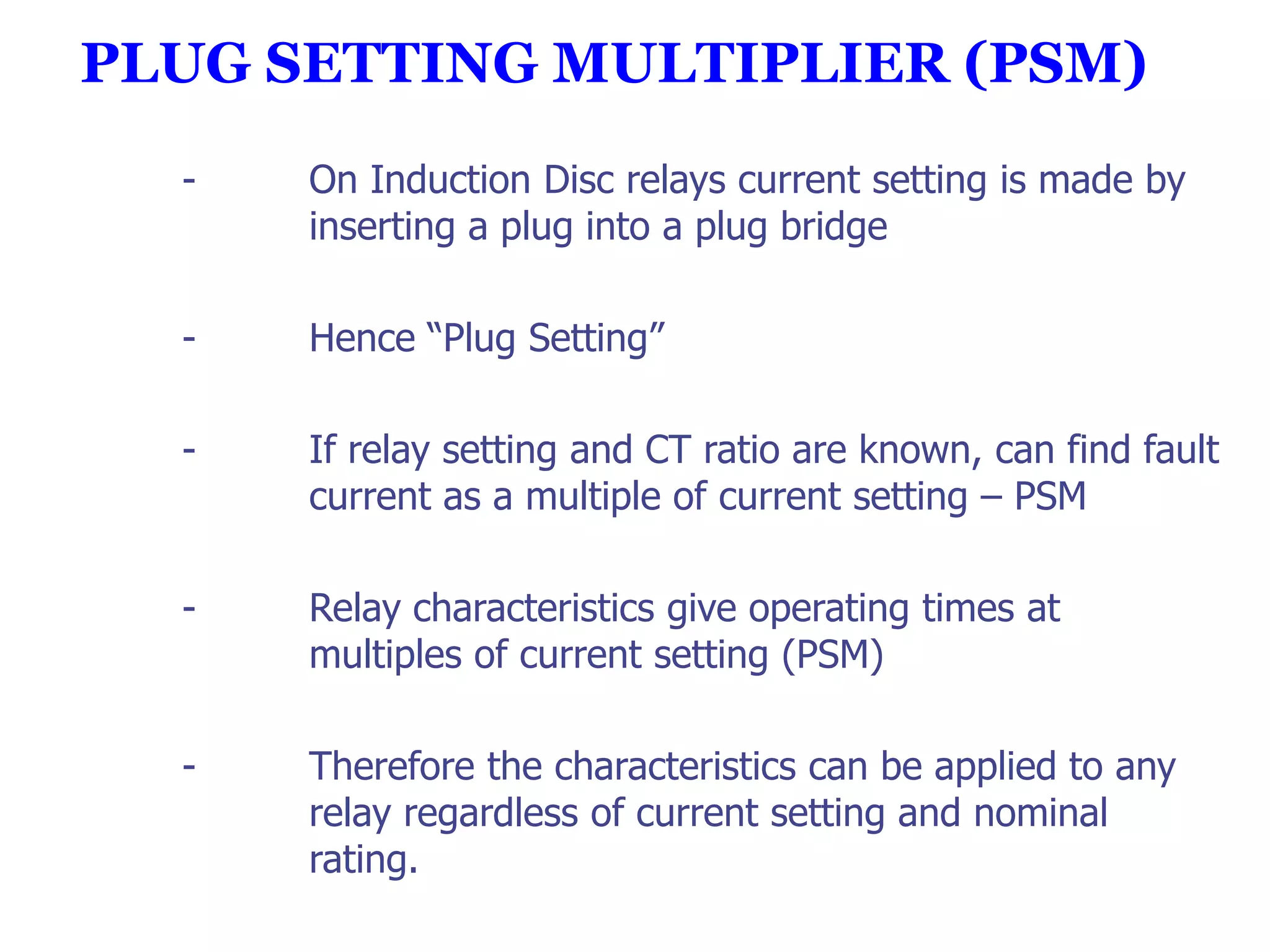
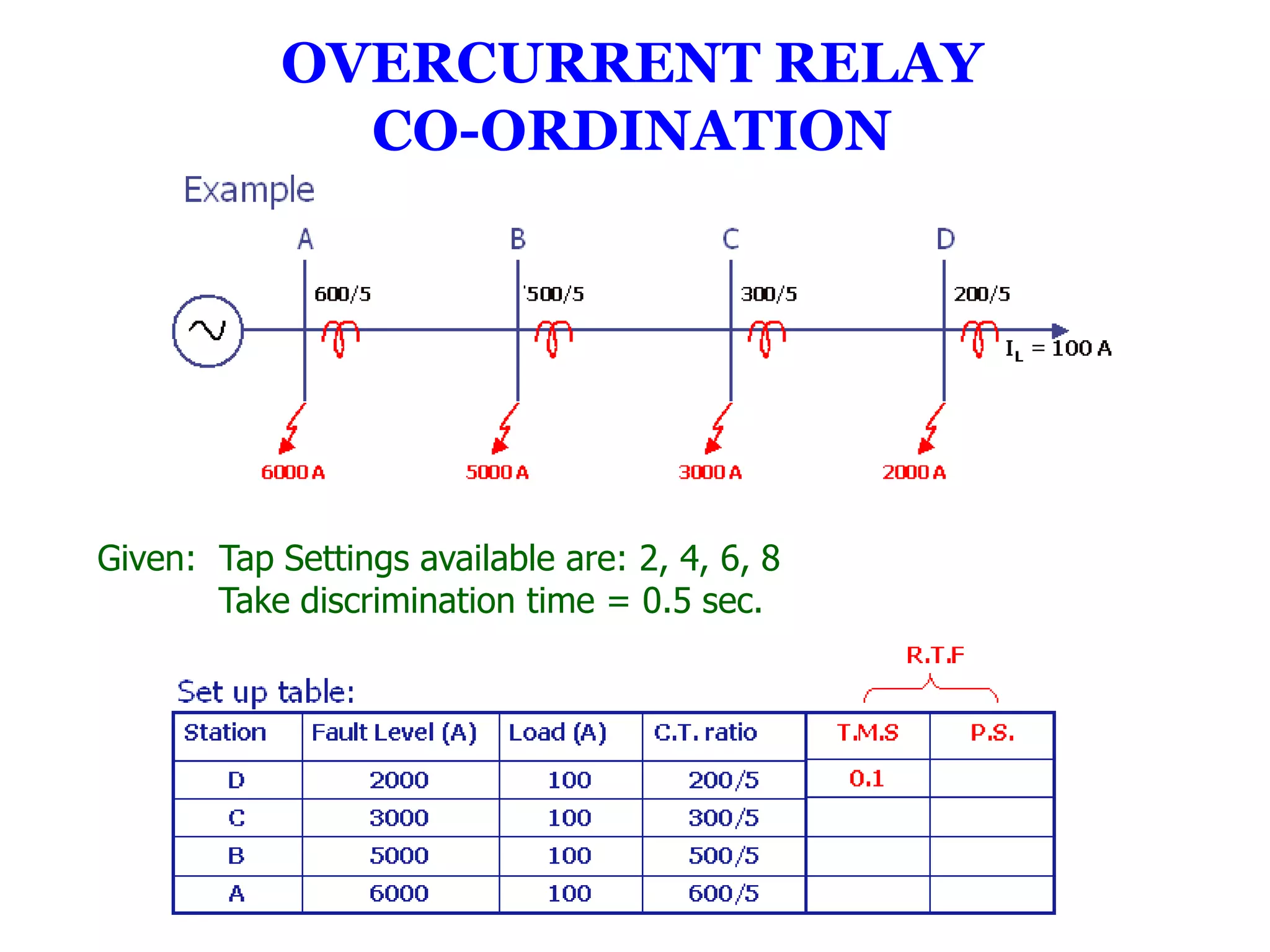
ECNG 3015
Industrial and Commercial
    Electrical Systems


        Lecturer
Prof Chandrabhan Sharma
          #4
   Overcurrent Relays
PLUG SETTING MULTIPLIER (PSM)
  -   On Induction Disc relays current setting is made by
      inserting a plug into a plug bridge

  -   Hence “Plug Setting”

  -   If relay setting and CT ratio are known, can find fault
      current as a multiple of current setting – PSM

  -   Relay characteristics give operating times at
      multiples of current setting (PSM)

  -   Therefore the characteristics can be applied to any
      relay regardless of current setting and nominal
      rating.
EXAMPLE
       CT Ratio = 100/1 A
       Fault Current = 1000 A


Relay current settings are made in % of CT ratings
       Is = 100% of 100 A
       Is = 100 A primary


PSM = If/Is    =      1000/100 = 10


So read off operating time at 10 x current setting
TIME MULTIPLIER SETTING (TMS)
      -      Not a time setting in seconds

      -      Multiplying factor which is applied to the basic
             relay operating time characteristic

For Grading:
Required operating time = TMS x operating time at TMS=1
IDMT RELAYS


      Grade „B‟ with „A‟ at IFMAX
      Both Relays Normal IDMT (3/10)
Relay A
      Current Setting = 5 AMP = 100 AMP (Pr)
      IFMAX = 1400 AMP = 14 x Setting
            PSM = 14
      Relay operating time at 14 x Setting and TMS of 0.05 is 0.13 seconds
Relay B
       Current Setting = 5 AMP = 200 AMP (Pr)


       IFMAX =1400 AMP = 7 x Setting


Relay operating time at 7 x setting and TMS of 1.0 is 3.6 sec.


Required operating time = 0.13 + 0.4 = 0.53 seconds


Therefore required TMS = 0.53/3.6 = 0.147


       Use TMS = 0.15 for relay B
OVERCURRENT RELAY
              CO-ORDINATION


Given: Tap Settings available are: 2, 4, 6, 8
       Take discrimination time = 0.5 sec.
Typical time/current characteristics of 3 seconds standard I.D.M.T.
                     – Available p.s. = 2, 4, 6, 8
Step 1: Start grading from extreme point i.e. load point
                Select the lowest TMS = 0.1


               ∴Select P.S. = 4
For fault at D bus:


       From IDMT curve for PSM 12.5 and TMS 1.0
       Operating time = 2.7 sec.
∴Actual operating time = (2.7)(0.1) = 0.27 sec.
Step 2:
        Relay C:
        For fault at D at 2000A
                Relay C should take (0.27 + 0.5) =0.77 sec.


  ∴Set P.S. for C at 2
  For fault at D:


Operating time from characteristic (TMS =1.0, PSMC 16.67)=2.45 s
       But relay must operate in 0.77 s
For Fault at C:


        ∴From characteristic, op. time = 2.2 s
        ∴ Actual op. time = (2.2)(.314) = 0.69 s
 Step 3: Relay B.
        For Fault of 3000 A (at C)
                  Operate TimeB = 0.69 + 0.5 = 1.19 s
 IL(B)= 100A


∴ Select P.S. = 2
∴ From characteristic → op. time = 2.5 s
         But breaker should operate in 1.19 s


For fault at B:


         ∴ Operating time =2.2 s
            Actual Operating time = 2.2 x 0.476 = 1.05 s

  For Relay at A: IL = 100


                                     ∴ P.S. =2
For fault at B(5000A), relay A should back up = 1.05 + 0.5 = 1.55 s


 ∴ Time to operate from characteristics = 2.32 s
EARTH FAULT PROTECTION

-   Earth fault current may be limited.


-   Sensitivity and speed requirements may not be
    met by overcurrrent relays.


-   Use separate earth fault relays.


-   Connect to measure residual (zero sequence)
    currents.


-   Therefore can be set to values less than full load
    current.
EARTH FAULT CONNECTIONS

Combined with Overcurrent Relays
For Economy, can use 2 x Overcurrent Relays
4-Wire Systems


 Earth Fault relay setting must be greater than “Normal” IN
DIFFERENTIAL PROTECTION
                   (Merz-Price Systems)
                     (Unit Protection)

                    3 Categories of Protection:

           •    Input and Output Terminals are close
                                       → transformer

       •       Where ends are Geographically Separate
                              → overhead/underground cables
                              → pilots at supply frequency used

               •   Very long lines          P.L.C.
                                → end → end signalling achieved
  by                              modulated carrier waveform.

Main difference is in way signals derived & transmitted.
Why needed?:-

      Overcomes application difficulties of simple O.C. Relays
       when applied to complex networks e.g. Co-ordination
          problems and excessive fault clearance times.

                         Principle:-

         Measurement of current at each end of feeder and
      transmission of information between each end of feeder.

Protection should operate for fault inside protected Zone only
                            →Stable for others.

           i.e. Instantaneous Operation Possible!
MERZ-PRICE SYSTEM
       Circulating Current Mode


-   Current confined to series path. No currents in relay


-   Both breakers tripped..
ANALYSIS OF THE MERZ-PRICE UNIT PROTECTION


              Relay operates when IA≠ IB
            but IC = IA- IB              ……… (1)
         ∴ Relay operates when


Let Nr = kNo where o<k<1               ………. (3)

        Sub into (2) equations (1) and (3)
          ∴ From which for threshold we have:
Question:
A 1 100kVA 2400/240V transformer is to be differentially protected.
Choose the C.T. ratios. Determine the ratio Nr/No if the relay is to tolerate
a mismatch in current of up to 20% of primary current (bias).
Solution:
Rated Primary Current of T/F : = 100/2.4 = 41.7 A
               ∴ Rated secondary = 41.7 x 10 = 417 A
                   For C.T. Secondary = 1A
                    Primary C.T. ratio   = 500:5
                    Secondary C.T. ratio = 5000:5

      For 20% mismatch (bias) → Reduction in Sensitivity
                  → IA = 0.8 IB (At threshold)


  or 2 - k = 1.6 + 0.8k          k = 0.222
OVERALL DIFFERENTIAL PROTECTION OF STAR/DELTA
             POWER TRANSFORMER
Recall:
Three-phase connections (Y/d)
For the above:


       Must Consider:       *       Magnetising inrush

         • Phase shift between primary and secondary

                        • Turns ratio

                    • Zero sequence cct.

      These can be compensated for by C.T. Connection

ECNG 3015 - Overcurrent Protection

  • 1.
    ECNG 3015 Industrial andCommercial Electrical Systems Lecturer Prof Chandrabhan Sharma #4 Overcurrent Relays
  • 2.
    PLUG SETTING MULTIPLIER(PSM) - On Induction Disc relays current setting is made by inserting a plug into a plug bridge - Hence “Plug Setting” - If relay setting and CT ratio are known, can find fault current as a multiple of current setting – PSM - Relay characteristics give operating times at multiples of current setting (PSM) - Therefore the characteristics can be applied to any relay regardless of current setting and nominal rating.
  • 3.
    EXAMPLE CT Ratio = 100/1 A Fault Current = 1000 A Relay current settings are made in % of CT ratings Is = 100% of 100 A Is = 100 A primary PSM = If/Is = 1000/100 = 10 So read off operating time at 10 x current setting
  • 4.
    TIME MULTIPLIER SETTING(TMS) - Not a time setting in seconds - Multiplying factor which is applied to the basic relay operating time characteristic For Grading: Required operating time = TMS x operating time at TMS=1
  • 5.
    IDMT RELAYS Grade „B‟ with „A‟ at IFMAX Both Relays Normal IDMT (3/10) Relay A Current Setting = 5 AMP = 100 AMP (Pr) IFMAX = 1400 AMP = 14 x Setting PSM = 14 Relay operating time at 14 x Setting and TMS of 0.05 is 0.13 seconds
  • 6.
    Relay B Current Setting = 5 AMP = 200 AMP (Pr) IFMAX =1400 AMP = 7 x Setting Relay operating time at 7 x setting and TMS of 1.0 is 3.6 sec. Required operating time = 0.13 + 0.4 = 0.53 seconds Therefore required TMS = 0.53/3.6 = 0.147 Use TMS = 0.15 for relay B
  • 8.
    OVERCURRENT RELAY CO-ORDINATION Given: Tap Settings available are: 2, 4, 6, 8 Take discrimination time = 0.5 sec.
  • 9.
    Typical time/current characteristicsof 3 seconds standard I.D.M.T. – Available p.s. = 2, 4, 6, 8
  • 10.
    Step 1: Startgrading from extreme point i.e. load point Select the lowest TMS = 0.1 ∴Select P.S. = 4 For fault at D bus: From IDMT curve for PSM 12.5 and TMS 1.0 Operating time = 2.7 sec. ∴Actual operating time = (2.7)(0.1) = 0.27 sec.
  • 11.
    Step 2: Relay C: For fault at D at 2000A Relay C should take (0.27 + 0.5) =0.77 sec. ∴Set P.S. for C at 2 For fault at D: Operating time from characteristic (TMS =1.0, PSMC 16.67)=2.45 s But relay must operate in 0.77 s
  • 12.
    For Fault atC: ∴From characteristic, op. time = 2.2 s ∴ Actual op. time = (2.2)(.314) = 0.69 s Step 3: Relay B. For Fault of 3000 A (at C) Operate TimeB = 0.69 + 0.5 = 1.19 s IL(B)= 100A ∴ Select P.S. = 2
  • 13.
    ∴ From characteristic→ op. time = 2.5 s But breaker should operate in 1.19 s For fault at B: ∴ Operating time =2.2 s Actual Operating time = 2.2 x 0.476 = 1.05 s For Relay at A: IL = 100 ∴ P.S. =2
  • 14.
    For fault atB(5000A), relay A should back up = 1.05 + 0.5 = 1.55 s ∴ Time to operate from characteristics = 2.32 s
  • 15.
    EARTH FAULT PROTECTION - Earth fault current may be limited. - Sensitivity and speed requirements may not be met by overcurrrent relays. - Use separate earth fault relays. - Connect to measure residual (zero sequence) currents. - Therefore can be set to values less than full load current.
  • 16.
    EARTH FAULT CONNECTIONS Combinedwith Overcurrent Relays
  • 17.
    For Economy, canuse 2 x Overcurrent Relays
  • 18.
    4-Wire Systems EarthFault relay setting must be greater than “Normal” IN
  • 19.
    DIFFERENTIAL PROTECTION (Merz-Price Systems) (Unit Protection) 3 Categories of Protection: • Input and Output Terminals are close → transformer • Where ends are Geographically Separate → overhead/underground cables → pilots at supply frequency used • Very long lines P.L.C. → end → end signalling achieved by modulated carrier waveform. Main difference is in way signals derived & transmitted.
  • 20.
    Why needed?:- Overcomes application difficulties of simple O.C. Relays when applied to complex networks e.g. Co-ordination problems and excessive fault clearance times. Principle:- Measurement of current at each end of feeder and transmission of information between each end of feeder. Protection should operate for fault inside protected Zone only →Stable for others. i.e. Instantaneous Operation Possible!
  • 21.
    MERZ-PRICE SYSTEM Circulating Current Mode - Current confined to series path. No currents in relay - Both breakers tripped..
  • 22.
    ANALYSIS OF THEMERZ-PRICE UNIT PROTECTION Relay operates when IA≠ IB but IC = IA- IB ……… (1) ∴ Relay operates when Let Nr = kNo where o<k<1 ………. (3) Sub into (2) equations (1) and (3) ∴ From which for threshold we have:
  • 23.
    Question: A 1 100kVA2400/240V transformer is to be differentially protected. Choose the C.T. ratios. Determine the ratio Nr/No if the relay is to tolerate a mismatch in current of up to 20% of primary current (bias).
  • 24.
    Solution: Rated Primary Currentof T/F : = 100/2.4 = 41.7 A ∴ Rated secondary = 41.7 x 10 = 417 A For C.T. Secondary = 1A Primary C.T. ratio = 500:5 Secondary C.T. ratio = 5000:5 For 20% mismatch (bias) → Reduction in Sensitivity → IA = 0.8 IB (At threshold) or 2 - k = 1.6 + 0.8k k = 0.222
  • 25.
    OVERALL DIFFERENTIAL PROTECTIONOF STAR/DELTA POWER TRANSFORMER
  • 26.
  • 27.
    For the above: Must Consider: * Magnetising inrush • Phase shift between primary and secondary • Turns ratio • Zero sequence cct. These can be compensated for by C.T. Connection