

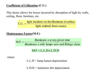
![Symbol Concept English Unit Metric Unit
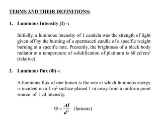
I Luminous Intensity
or Candle Power
Candela (cd) Candela (cd)
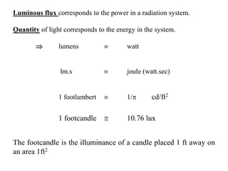
Luminous Flux Lumen (lm) Lumen (lm)
E Illuminance Lumen/ft2
(footcandle [fc])
Lumen/m2
(lux or lx)
M Luminous Exitance Lumen/ft2 Lumen/m2
L Luminance cd/ft2
(footlambert)
cd/m2 (nit)
Q Quantity of Light lm.s lm.s
ENTITIES IN ILLUMINATION ENGINEERING](https://image.slidesharecdn.com/ices-chapter8-illuminationengineering-180224162300/85/Ices-chapter-8-illumination-engineering-8-320.jpg)
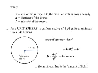
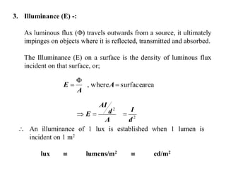
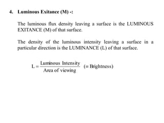
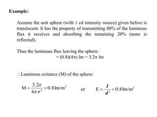
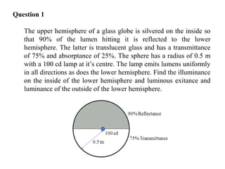
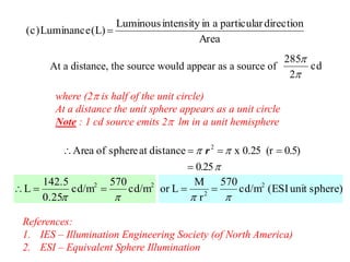
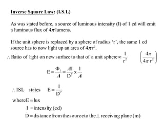
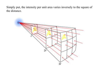
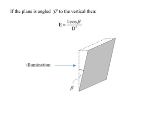
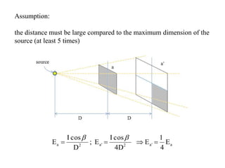
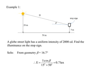
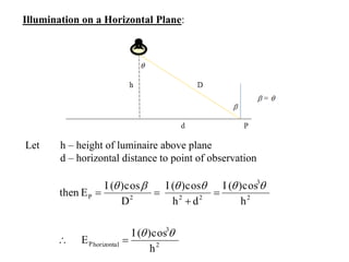
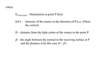
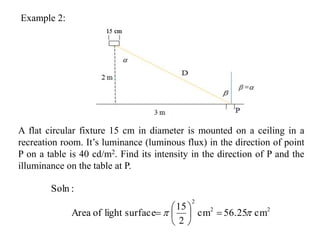
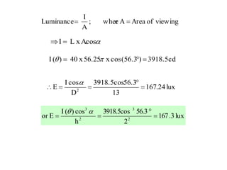
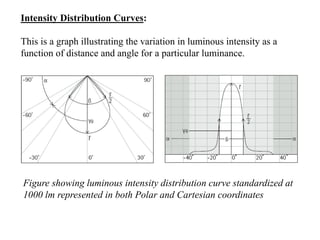
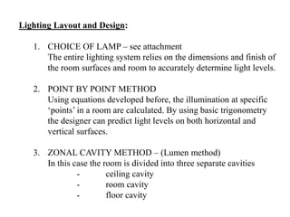
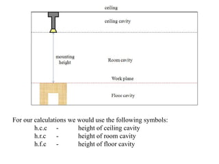
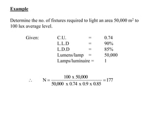
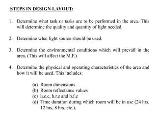
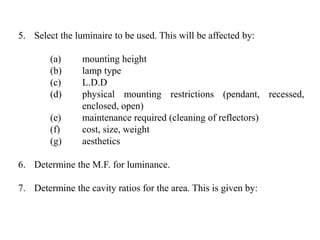
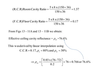
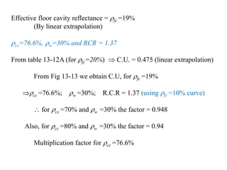
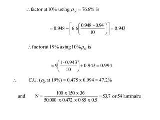
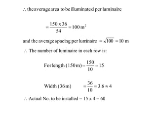

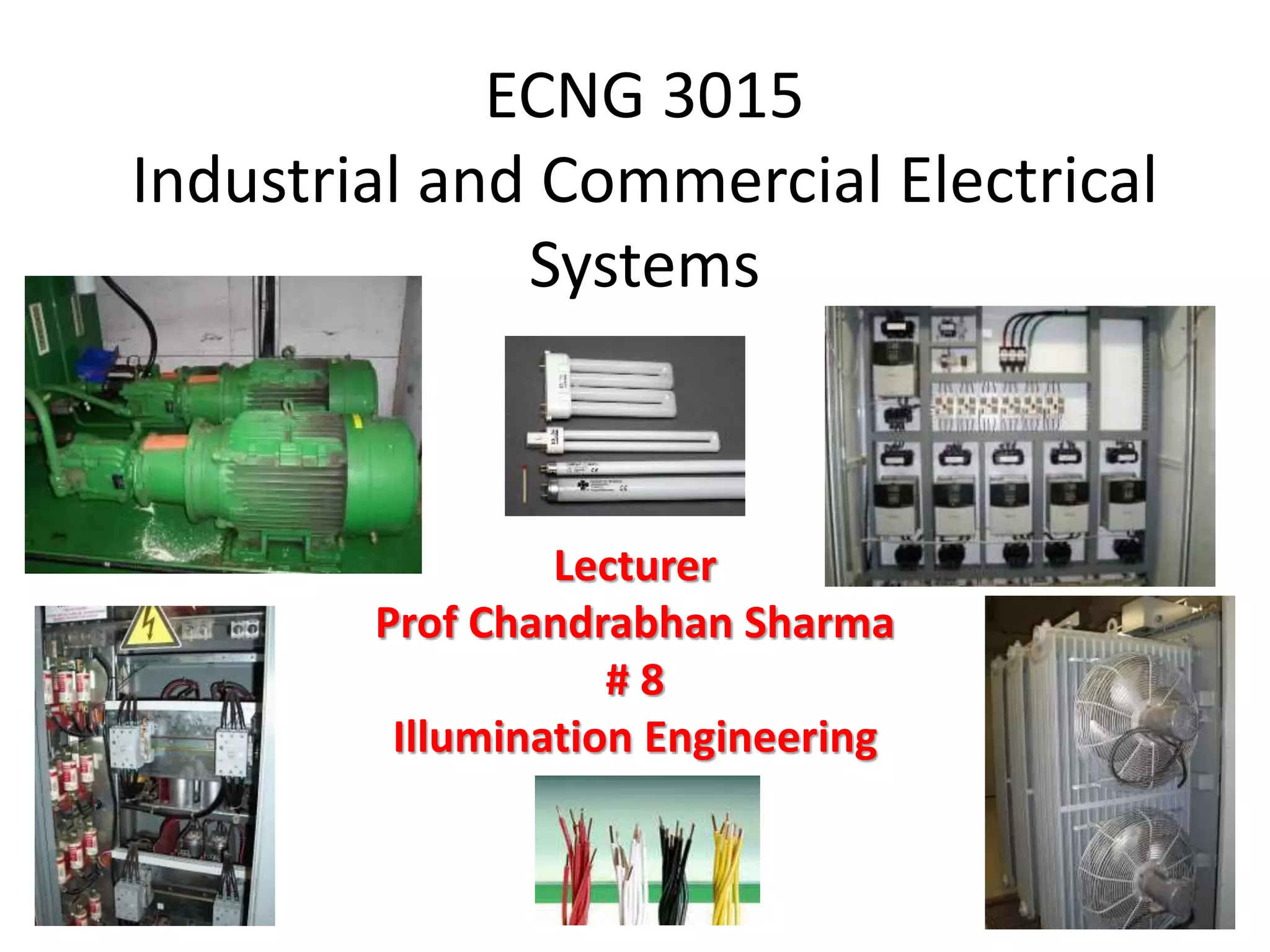
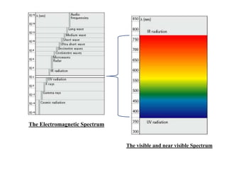
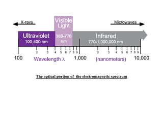
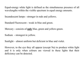
This document discusses illumination engineering and provides definitions and formulas for key terms. It describes: 1. The electromagnetic spectrum and visible light spectrum. 2. Terms like luminous intensity, luminous flux, illuminance, luminous exitance, and luminance and their definitions and relationships. 3. How to calculate illuminance on surfaces using the inverse square law and other formulas, accounting for factors like source intensity, distance, and angle to the surface. 4. Intensity distribution curves and how they illustrate light output as a function of angle. 5. The zonal cavity method for lighting layout and design, which divides a room into cavities and calculates light levels based on factors like room dimensions


