


![1
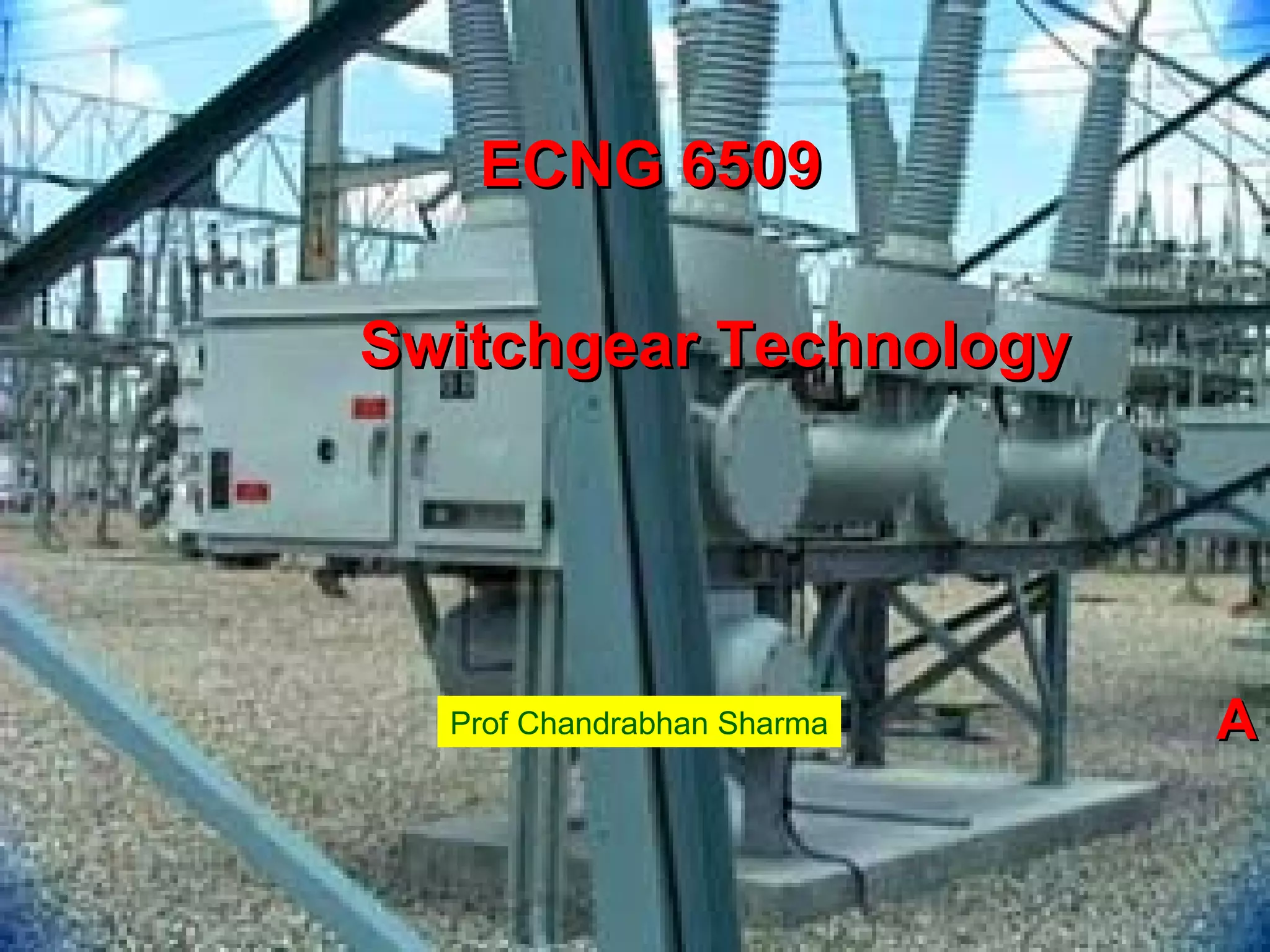
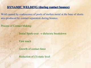
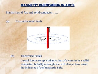
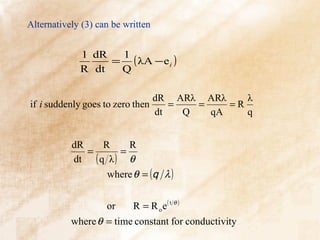
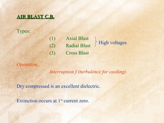
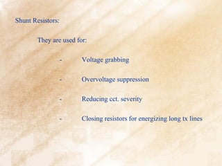
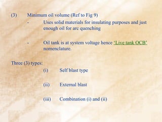
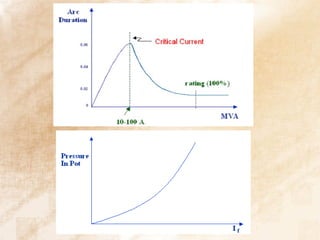
Also, = f (Q) where Q - energy content/unit length
R
From the 1st Law of Thermodynamics :
dQ
W=N+ + w ; where w - work done by arc
dt
neglecting w
⇒ Q = ∫ (W − N)dt
1
and = f (Q) = f [ ∫(W − N)dt] ..............................(1)
R
f ' (Q) dQ f ' (Q)
R d( 1 R ) = = (W − N) ................................(2)
f (Q) dt f (Q)](https://image.slidesharecdn.com/switchgeartechnologyanimatedwithbackground-130226163314-phpapp01/85/ECNG-6509-Switchgear-Technology-17-320.jpg)

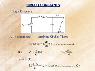
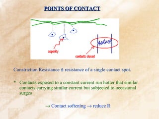
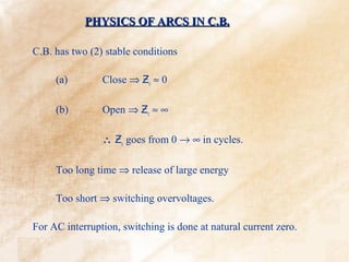
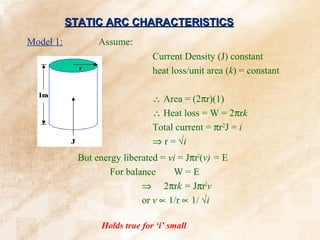
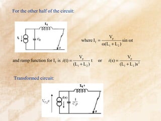
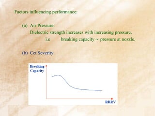
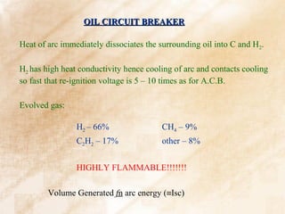
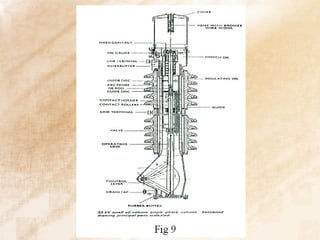
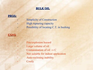
![Also VC(0) = arc voltage ; which is negligible
2
s ω0
⇒ VC (s) = Vm 2 2
.......................(7)
(s + ω )(s + ω0 )
2 2
From partial fraction analysis:
s 1 s s
= 2 2 2
− 2 2
(s + ω )(s + ω0 ) (ω0 − ω ) (s + ω ) (s + ω0 )
2 2 2 2 2
Sub into (7)
ω02
s s
VC (s) = Vm 2 − 2 2
(ω0 − ω 2 ) (s 2 + ω 2 ) (s + ω0 )
Taking inverse:
2
ω0 1
VC (t) = 2 Vm [ cos ωt - cos ω0 t ] ; where ω0 =
(ω0 − ω 2 ) LC](https://image.slidesharecdn.com/switchgeartechnologyanimatedwithbackground-130226163314-phpapp01/85/ECNG-6509-Switchgear-Technology-24-320.jpg)
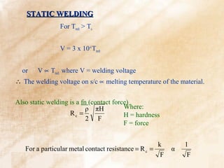
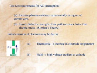
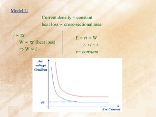
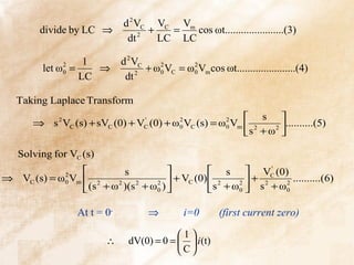
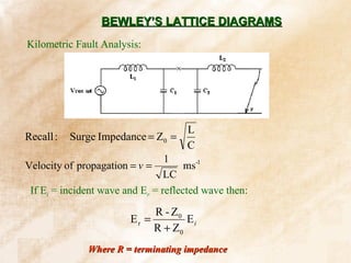
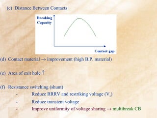
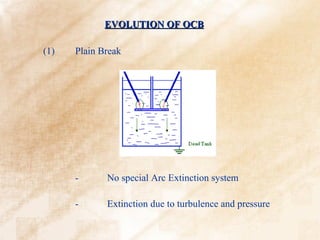
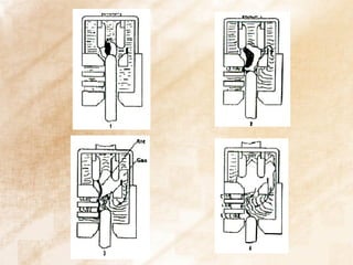
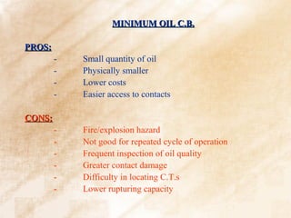
![For most circuits: C << small and ω0 >> ω
2
ω0
∴ 2 →1
(ω0 − ω )
2
∴ VC (t) = Vm [ cos ωt - cos ω0 t ]
Also for period of analysis, the power terms is constant w.r.t. ω0
∴ equation becomes VC (t) = Vm [1 - cos ω0 t ]
(1) Max. restrike voltage = VC(max)(t) = 2 Vm
π
which occurs at t = or π LC
ω0
1
and f 0 =
2π LC](https://image.slidesharecdn.com/switchgeartechnologyanimatedwithbackground-130226163314-phpapp01/85/ECNG-6509-Switchgear-Technology-25-320.jpg)
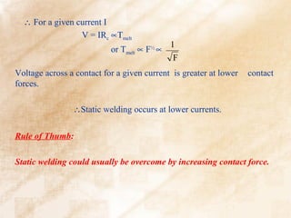
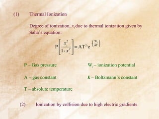
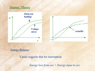
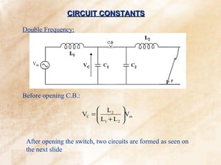
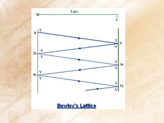
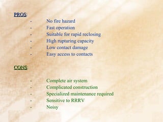
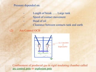
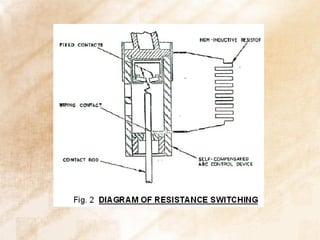
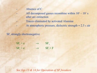
![Rate of Rise of Recovery Voltage [RRRV]
dVC
RRRV = (kV/µs)
dt max
2Vm
⇒ RRRV = (kV/µs)
t
π 2V ω
when t = ⇒ RRRV = m 0
ω0 π
dVC
Aside : = Vm ω0 sin ω0 t
dt
dVC π
For ⇒ Vm ω0 sin ω0 t = 0 ⇒ sin ω0 t = 0 or t =
dt maximum ω0](https://image.slidesharecdn.com/switchgeartechnologyanimatedwithbackground-130226163314-phpapp01/85/ECNG-6509-Switchgear-Technology-26-320.jpg)
![2
ω1 1 s
But = − 2
s(s + ω1 ) s s + ω1
2 2 2
L1 1 s
∴ VC (s) =
L + L s s + ω2
Vp − 2
1 2 1
L1
⇒ L + L Vp [1 - cos ω1t ]
VC (t) =
1 2
L2
From before VC ss =
L + L Vp cos ωt
1 2
L2 L1
∴ VC = VC ss + VT =
L +L L + L Vp [1 - cos ω1t ]
Vp cos ωt +
1 2 1 2 ](https://image.slidesharecdn.com/switchgeartechnologyanimatedwithbackground-130226163314-phpapp01/85/ECNG-6509-Switchgear-Technology-33-320.jpg)
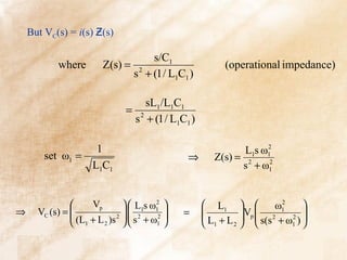
![From circuit VC(s) = - i(s) Ƶ(s)
L 2 /C 2 L 2s ω 2 1
where Z(s) = = 2 2
and ω 2 =
L 2s + 1 / C 2s s + ω 2 2 L 2C 2
L2 1 s
∴ VC (s) = −
L + L s s + ω2
Vp − 2
1 2 2
L2
⇒ L + L Vp [ cos ω 2 t - 1]
VC (t) =
1 2
∴ VC 2 = VC ss + VT
L2 L2
L + L Vp + L + L Vp [ cos ω 2 t - 1]
=
1 2 1 2 ](https://image.slidesharecdn.com/switchgeartechnologyanimatedwithbackground-130226163314-phpapp01/85/ECNG-6509-Switchgear-Technology-35-320.jpg)
![ L2
=
L + L Vp cos ω 2 t
1 2
L2 L1 L2
=
L +L Vp cos ωt +
L +L Vp [1 - cos ω1t ] −
L + L Vp cos ω 2 t
1 2 1 2 1 2 ](https://image.slidesharecdn.com/switchgeartechnologyanimatedwithbackground-130226163314-phpapp01/85/ECNG-6509-Switchgear-Technology-36-320.jpg)


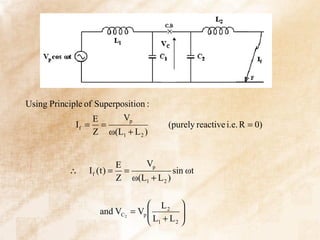
The document discusses switchgear technology and circuit breaker operation. It covers several topics in 3 sentences or less: Static welding of contacts can be overcome by increasing contact force and occurs at lower currents than dynamic welding. Arc interruption requires increasing plasma resistance at current zero and ensuring dielectric strength increases faster than electric stress. In a double frequency circuit, the voltages on the two circuits after opening will be proportional to the inductances in each circuit divided by the total inductance.


