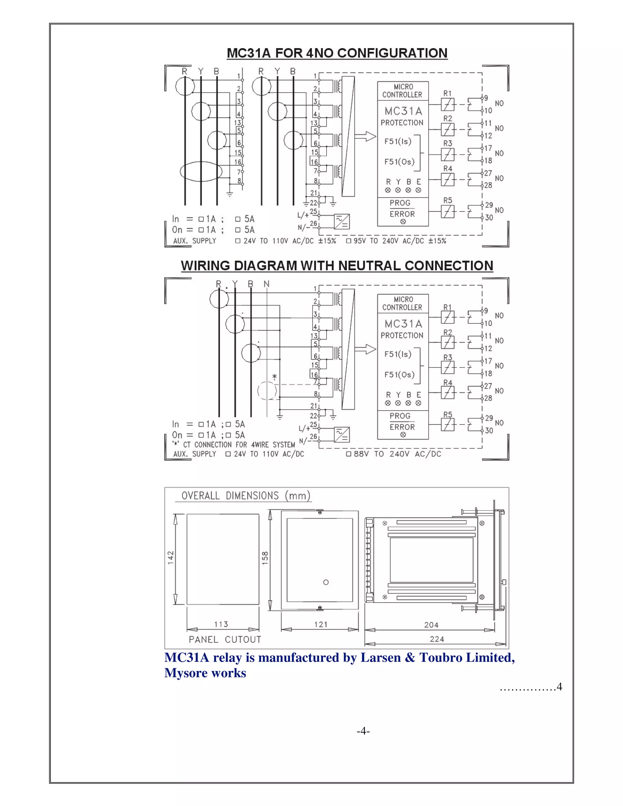
THREE PHASE OVER CURRENT +
EARTH FAULT RELAY
TYPE MC31A
Relay MC31A is a three phase over current + Earth fault relay with 4 measuring elements.
The relay can be used for feeder protection in all low voltage, medium voltage and high
voltage sub-stations. The relay has a front panel 4 digit seven segment LED display to read
various settings,on line values, switch on values, last trip data etc. User has a choice of 7 trip
time characteristics.
TECHNICAL SPECIFICATIONS
1.0 Rated Current 1A or 5A (Field selectable)
2.0 Rated Frequency 50Hz ± 2.5 Hz
3.0 Auxiliary Power Supply 24V to 110V AC/DC ± 15% or
95V to 240V AC/DC ± 15%
4.0 Relay Settings :
Over Current (Is) 0.2 to 2.0 times In, in steps of 0.05In
Earth Fault (Os) 0.05 to 0.8 times On in steps of 0.05 On
Time Multiplier 0.1 to 1.6 in steps of 0.05 (independent settings for O/C
& E/F modes)
5.0 Operating Characteristics Front panel programmable , using push buttons.
Time /Current Separate characteristics can be selected for O/C &
characteristics E/F modes.
a) Normal Inverse (NI) 3s
b) Normal Inverse (NI) 1.3s
c) Very Inverse (VI)
d) Extremely Inverse (EI)
e) Definite Time (DT) 1s
f) Definite time (DT) 10s
g) Definite time (DT) 100s
……………….2
-2-
Three Phase Over current
Earth Fault
Inverse & Definite time trip Characteristics
4 digit display
CT secondary 1A / 5A field selectable
50 / 51, 50N/ 51N
Accuracy As per Error class 5 of IS: 3231: 1987
Pick up current Same as set current
Reset Current 95% to 90% of pick up current
Reset time 0.1 to 10sec in steps of 0.1 sec or less than 50 ms
6.0 Burden Less than 0.25 VA/ phase at CT inputs
Less than 10 VA at Auxiliary Power supply
7.0 Operation Indicators Separate LED indications for :
• Power on
• Trip status for R, Y, B & E
(these LEDs blink when input crosses set point and
become steady on when relay has tripped. LEDs
have to be manually reset)
• 4 digit , seven segment LEDs for parameter display
8.0 Output Relay Contacts • 4 contacts for trip signal on feeder faults
( one version with 2N/O + 2 N/C and
other version with 4 N/O).
• 1 N/C contact for internal relay fault
9.0 Output contact rating
Rated voltage 250 V AC / 30 V DC
Rated current 8A
Rated Breaking Capacity 2000VA / 240 W (Resistive)
10.0 Over Load capacity 2 times rated current continuously
20 times rated current for 1 sec
11.0 Electrical performance Please refer separate document
Specifications “General Electrical Characteristics”
12.0 Case
Front Bezel 158 x 136 mm
Panel Cutout 142 x 113 mm
Depth 224 mm
13.0 Weight 1.5 kG approx.
……………….3
-3-
MC31A relay is manufactured by Larsen & Toubro Limited,
Mysore works
……………4
-4-
………….5
-5-
CATALOG NOs.
MC31AAXX000
MC31AAXX001
MC31ABXX000
MC31ABXX001
ORDERING INFORMATION :
1) Auxiliary Power supply Type A or Type B
2) Contact configuration 4 N/O or 2 N/0 + 2 N/C
3 1 A AC X XM 0 0 0
Contact Configuration
0 = 4 N/O
1 = 2 N/O + 2 N/C
Aux. Power supply
A = 24 to 110 V AC/DC ±±±± 10%
B = 110 to 240 V AC/DC ±±±± 10%

Over-current-earth-fault-relay-MC-31

  • 1.
    THREE PHASE OVERCURRENT + EARTH FAULT RELAY TYPE MC31A Relay MC31A is a three phase over current + Earth fault relay with 4 measuring elements. The relay can be used for feeder protection in all low voltage, medium voltage and high voltage sub-stations. The relay has a front panel 4 digit seven segment LED display to read various settings,on line values, switch on values, last trip data etc. User has a choice of 7 trip time characteristics. TECHNICAL SPECIFICATIONS 1.0 Rated Current 1A or 5A (Field selectable) 2.0 Rated Frequency 50Hz ± 2.5 Hz 3.0 Auxiliary Power Supply 24V to 110V AC/DC ± 15% or 95V to 240V AC/DC ± 15% 4.0 Relay Settings : Over Current (Is) 0.2 to 2.0 times In, in steps of 0.05In Earth Fault (Os) 0.05 to 0.8 times On in steps of 0.05 On Time Multiplier 0.1 to 1.6 in steps of 0.05 (independent settings for O/C & E/F modes) 5.0 Operating Characteristics Front panel programmable , using push buttons. Time /Current Separate characteristics can be selected for O/C & characteristics E/F modes. a) Normal Inverse (NI) 3s b) Normal Inverse (NI) 1.3s c) Very Inverse (VI) d) Extremely Inverse (EI) e) Definite Time (DT) 1s f) Definite time (DT) 10s g) Definite time (DT) 100s ……………….2 -2- Three Phase Over current Earth Fault Inverse & Definite time trip Characteristics 4 digit display CT secondary 1A / 5A field selectable 50 / 51, 50N/ 51N
  • 2.
    Accuracy As perError class 5 of IS: 3231: 1987 Pick up current Same as set current Reset Current 95% to 90% of pick up current Reset time 0.1 to 10sec in steps of 0.1 sec or less than 50 ms 6.0 Burden Less than 0.25 VA/ phase at CT inputs Less than 10 VA at Auxiliary Power supply 7.0 Operation Indicators Separate LED indications for : • Power on • Trip status for R, Y, B & E (these LEDs blink when input crosses set point and become steady on when relay has tripped. LEDs have to be manually reset) • 4 digit , seven segment LEDs for parameter display 8.0 Output Relay Contacts • 4 contacts for trip signal on feeder faults ( one version with 2N/O + 2 N/C and other version with 4 N/O). • 1 N/C contact for internal relay fault 9.0 Output contact rating Rated voltage 250 V AC / 30 V DC Rated current 8A Rated Breaking Capacity 2000VA / 240 W (Resistive) 10.0 Over Load capacity 2 times rated current continuously 20 times rated current for 1 sec 11.0 Electrical performance Please refer separate document Specifications “General Electrical Characteristics” 12.0 Case Front Bezel 158 x 136 mm Panel Cutout 142 x 113 mm Depth 224 mm 13.0 Weight 1.5 kG approx. ……………….3 -3-
  • 3.
    MC31A relay ismanufactured by Larsen & Toubro Limited, Mysore works ……………4 -4-
  • 4.
  • 5.
    MC31AAXX000 MC31AAXX001 MC31ABXX000 MC31ABXX001 ORDERING INFORMATION : 1)Auxiliary Power supply Type A or Type B 2) Contact configuration 4 N/O or 2 N/0 + 2 N/C 3 1 A AC X XM 0 0 0 Contact Configuration 0 = 4 N/O 1 = 2 N/O + 2 N/C Aux. Power supply A = 24 to 110 V AC/DC ±±±± 10% B = 110 to 240 V AC/DC ±±±± 10%