The document is a British Standard BS 7430:2011+A1:2015 that outlines the code of practice for protective earthing of electrical installations. It provides recommendations and guidance to ensure safety in low voltage and high voltage electrical systems, detailing the principles of earthing, types of installations, and inspection protocols. The standard applies specifically to land-based installations and does not cover equipment such as ships or offshore installations.
![Foreword
Publishing information
This British Standard is published by BSI Standards Limited, under licence from
The British Standards Institution, and came into effect on 31 December 2011. It
was prepared by Technical Committee GEL/600, Earthing. A list of organizations
represented on this committee can be obtained on request to its secretary.
Supersession
This British Standard supersedes BS 7430:2011, which is withdrawn.
Information about this document
Text introduced or altered by Amendment No. 1 is indicated in the text by tags
. Minor editorial changes are not tagged.
Relationship with other publications
This revision of BS 7430 takes into account changes in legislation
(implementation of the Electricity Safety, Quality and Continuity
Regulations 2002 as amended [1]) and changes in and publication of other
relevant industry standards such as BS 7671:2008+A3:2015,
BS EN IEC 61936-1:2011 and BS EN 50522:2011.
Legislation
In Great Britain earthing of an electricity supply system is governed by the
Electricity Safety, Quality and Continuity Regulations 2002 as amended
(ESQCR) [1] and the Electricity at Work Regulations 1989 [2]. In Northern
Ireland, the Electricity Safety, Quality and Continuity Regulations 2012 (Northern
Ireland) as amended [ESQCR (NI)] apply [3].
Presentational conventions
The provisions in this standard are presented in roman (i.e. upright) type. Its
recommendations are expressed in sentences in which the principal auxiliary
verb is “should”.
Commentary, explanation and general informative material is presented in
smaller italic type, and does not constitute a normative element.
The word “should” is used to express recommendations of this standard. The
word “may” is used in the text to express permissibility, e.g. as an alternative to
the primary recommendation of the Clause. The word “can” is used to express
possibility, e.g. a consequence of an action or an event.
Notes and commentaries are provided throughout the text of this standard.
Notes give references and additional information that are important but do not
form part of the recommendations. Commentaries give background information.
Contractual and legal considerations
This publication does not purport to include all the necessary provisions of a
contract. Users are responsible for its correct application.
Compliance with a British Standard cannot confer immunity from legal
obligations.
BRITISH STANDARD BS 7430:2011+A1:2015
© The British Standards Institution 2015 • iii
www.TeraStandard.com
--``,`,`,`,,,,`,,,,,,,`,,`,,```,-`-`,,`,,`,`,,`---](https://image.slidesharecdn.com/560446183-kz1o3nvhwcbs-7430-a1-2015-250126112157-f88d272d/85/EARTHING-SYSTEM-CALCULATION-WITH-EARTHIG-STRIP-SIZE-5-320.jpg)
![1 Scope
This British Standard primarily provides recommendations and guidance on
meeting the requirements for the earthing of electrical installations, including:
a) protective earthing of low voltage installations to
BS 7671:2008+A3:2015;
b) the interface between LV and HV substations of 11 000/400 V to
BS EN 61936-1:2010+A1:2014 within buildings; and
c) protective earthing and changeover switch arrangements for generators
supplying low voltage installations.
The earthing of a system or installation is generally provided for reasons of
safety.
This British Standard applies only to land-based installations in and around
buildings. It does not apply to:
1) ships, aircraft or offshore installations;
2) earthing of medical equipment [see BS EN 60601 (all parts)];
3) special problems encountered with solid state electronic components;
4) equipment sensitive to static electricity;
5) requirements for functional earthing;
6) earthing of overhead lines between electrical installations; or
7) the internal earthing of equipment.
2 Normative references
The following referenced documents are indispensable for the application of
this document. For dated references, only the edition cited applies. For undated
references, the latest edition of the referenced document (including any
amendments) applies.
BS 215-2:1970, Specification for aluminium conductors and aluminium
conductors, steel-reinforced for overhead power transmission – Aluminium
conductors, steel-reinforced (withdrawn)
BS 729, Specification for hot dip galvanized coatings on iron and steel articles
(withdrawn)
BS 951, Electrical earthing – Clamps for earthing and bonding – Specification
BS 1400, Specification for copper alloy ingots and copper alloy and high
conductivity copper castings (withdrawn)
BS 1449:1991 (all parts), Steel plate, sheet and strip (withdrawn)
BS 1473:1972, Specification for wrought aluminium and aluminium alloys for
general engineering purposes – Rivet, bolt and screw stock
BS 1474:1987, Specification for wrought aluminium and aluminium alloys for
general engineering purposes: bars, extruded round tubes and sections
(withdrawn)
BS 1561:1997, Founding – Grey cast irons
BS 1562:1997, Founding – Malleable cast irons
BS 1377-3, Methods of test for soils for civil engineering purposes – Part 3:
Chemical and electro-chemical tests
Text deleted
BRITISH STANDARD BS 7430:2011+A1:2015
© The British Standards Institution 2015 • 1
www.TeraStandard.com
--``,`,`,`,,,,`,,,,,,,`,,`,,```,-`-`,,`,,`,`,,`---](https://image.slidesharecdn.com/560446183-kz1o3nvhwcbs-7430-a1-2015-250126112157-f88d272d/85/EARTHING-SYSTEM-CALCULATION-WITH-EARTHIG-STRIP-SIZE-7-320.jpg)
![3 Terms and definitions
For the purposes of this British Standard, the terms and definitions given in
BS 7671:2008+A3 and BS IEC 60050-195, together with the following
apply.
3.1 earth grid
earth electrode in the form of two overlapping groups of buried, parallel,
horizontal electrodes, usually laid approximately at right angles to each other,
with the electrodes bonded at each intersection
3.2 earth potential
electric potential with respect to the general mass of earth which occurs in, or
on the surface of, the ground around an earth electrode when an electric
current flows from the electrode to earth
3.3 earth potential rise
voltage between an earthing system and reference earth
[BS EN 50522:2011]
3.4 earth resistance
resistance to earth of an earth electrode or earth grid
3.5 earthing system
arrangement of connections and devices necessary to earth equipment or a
system separately or jointly
[IEC 60050-604, 604-04-02]
3.6 global earthing system
equivalent earthing system created by the interconnection of local earthing
systems that ensures, by the proximity of the earthing systems, that there are no
dangerous touch voltages
NOTE 1 Such systems permit the division of the earth fault current in a way that
results in a reduction of the earth potential rise at the local earthing system. Such a
system could be said to form a quasi equipotential surface.
NOTE 2 The existence of a global earthing system may be determined by sample
measurements or calculation for typical systems. Typical examples of global earthing
systems are in city centres; urban or industrial areas with distributed low- and
high-voltage earthing.
[BS EN 50522:2011]
3.7 hot site
substation where the rise of earth potential, under the maximum earth fault
condition, can exceed the value either 430 V or 650 V depending upon the fault
clearance time
3.8 potential gradient (at a point)
rate of change of voltage measured at that point in the direction in which it is a
maximum
3.9 transferred potential
potential rise of an earthing system caused by a current to earth transferred by
means of a connected conductor (for example a metallic cable sheath,
PEN conductor, pipeline, rail) into areas with low or no potential rise relative to
reference earth resulting in a potential difference occurring between the
conductor and its surroundings
BRITISH STANDARD
BS 7430:2011+A1:2015
4 • © The British Standards Institution 2015
www.TeraStandard.com
--``,`,`,`,,,,`,,,,,,,`,,`,,```,-`-`,,`,,`,`,,`---](https://image.slidesharecdn.com/560446183-kz1o3nvhwcbs-7430-a1-2015-250126112157-f88d272d/85/EARTHING-SYSTEM-CALCULATION-WITH-EARTHIG-STRIP-SIZE-10-320.jpg)
![NOTE 1 The definition also applies where a conductor, which is connected to
reference earth, leads into the area of the potential rise.
NOTE 2 Transferred potentials can result in electrocution paths through the human
body other than the “touch voltage” path, e.g. hand to hand.
[BS EN 50522:2011]
3.10 (effective) touch potential
voltage between conductive parts when touched simultaneously
NOTE The value of the effective touch voltage may be appreciably influenced by
the impedance of the person in electric contact with these conductive parts.
[BS IEC 60050-195, 195-05-11, modified]
3.11 prospective touch potential
voltage between simultaneously accessible conductive parts when those
conductive parts are not being touched
[IEV 195-05-09, modified]
3.12 step voltage
step potential
voltage between two points on the earth’s surface that are 1 m distant from
each other, which is considered to be the stride length of a person
[BS IEC 60050-195, 195-05-12]
3.13 transferred potential
potential rise of an earthing system caused by a current to earth transferred by
means of a connected conductor (for example a metallic cable sheath,
PEN conductor, pipeline, rail) into areas with low or no potential rise relative to
reference earth resulting in a potential difference occurring between the
conductor and its surroundings
NOTE 1 The definition also applies where a conductor, which is connected to
reference earth, leads into the area of the potential rise.
NOTE 2 Transferred potentials can result in electrocution paths through the human
body other than the “touch voltage” path, e.g. hand to hand.
[BS EN 50522:2011]
4 Earthing principles
4.1 Fundamental rule of protection against electric shock
BS EN 61140 gives fundamental principles and requirements which are common
to electrical installations, systems and equipment or necessary for their
co-ordination, for installations, systems and equipment without a voltage limit.
BS EN 61140 states that the fundamental rule of protection against electric
shock is that:
• …hazardous-live-parts shall not be accessible and accessible conductive
parts shall not be hazardous live:
• either under normal conditions (operation in intended use,
see ISO/IEC Guide 51, 3.13 and absence of a fault); or
• under single-fault conditions (see also IEC Guide 104, 2.8).
The system and equipment standards are being amended to comply with
BS EN 61140 so that the fundamental rule is met and to adopt the same
terminology.
BRITISH STANDARD BS 7430:2011+A1:2015
© The British Standards Institution 2015 • 5
www.TeraStandard.com
--``,`,`,`,,,,`,,,,,,,`,,`,,```,-`-`,,`,,`,`,,`---](https://image.slidesharecdn.com/560446183-kz1o3nvhwcbs-7430-a1-2015-250126112157-f88d272d/85/EARTHING-SYSTEM-CALCULATION-WITH-EARTHIG-STRIP-SIZE-11-320.jpg)
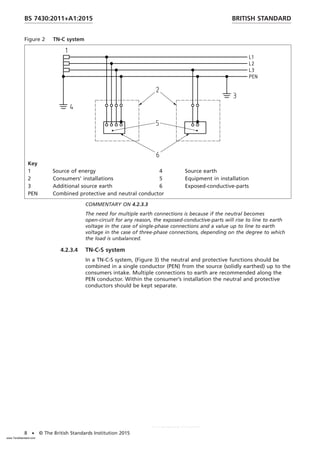
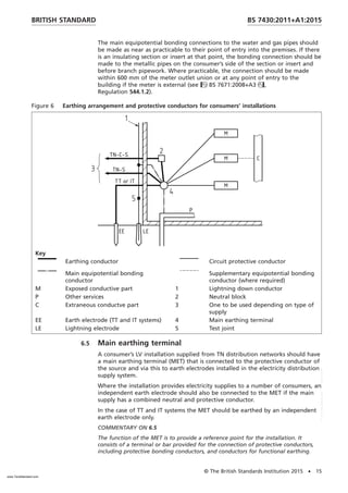
![In order to achieve the principles within BS EN 61140 within electrical
installations standards, BS 7671:2008+A3 makes certain requirements for
the earthing of an installation and its sub-structure in order to achieve safety.
With the exception of earth free locations, the main requirement under single
fault conditions is for automatic disconnection of supply with selecting cable
impedances in order to achieve certain touch voltages.
4.2 Supply system earthing
4.2.1 Legislation
In Great Britain the earthing of an electricity supply system is covered by the
requirements of the Electricity Safety Quality and Continuity Regulations 2002 as
amended (ESQCR) [1]. Part II, Protection and Earthing is particularly relevant to
users of this standard. Guidance is given in DTI publication Guidance on the
Electricity Safety, Quality and Continuity Regulations [4].
In Northern Ireland, the Electricity Safety, Quality and Continuity
Regulations 2012 (Northern Ireland) as amended [ESQCR (NI)] apply [3]. The
general provisions in the ESQCR [1] apply to both overhead and underground
systems of supply.
The regulations require that every network at whatever voltage be connected
with Earth and that the connection is maintained under fault conditions
[Regulation 8(1)]. This requirement is designed primarily to preserve the security
of the system by ensuring that the potential on each conductor is restricted to
such a value as is consistent with the level of insulation applied. Every supply
neutral conductor (of LV networks) is required to be connected with earth
generally at the source of voltage [Regulation 8 (3(b))].
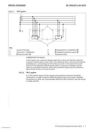
The regulations include a particular requirement where the neutral and
protective conductors are combined that is in protective multiply earthed (PME)
systems (see Regulation 9). This is the most common system adopted,
see Figure 3.
4.2.2 High voltage (HV) power supply systems
NOTE Requirements for earthing HV installations are given in
BS EN 61936-1:2010+A1:2014 and BS EN 50522:2011. See also Clause 5.
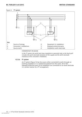
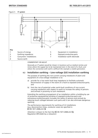
4.2.3 Classification of low voltage systems
4.2.3.1 General
For the purpose of this standard the following earthing systems are defined:
TN-S, TN-C, TN-C-S, TT and IT.
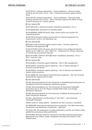
4.2.3.2 TN-S system
In a TN-S (Figure 1) the Neutral and Protective conductors should be kept
separate throughout the system and the source is solidly earthed.
BRITISH STANDARD
BS 7430:2011+A1:2015
6 • © The British Standards Institution 2015
www.TeraStandard.com
--``,`,`,`,,,,`,,,,,,,`,,`,,```,-`-`,,`,,`,`,,`---](https://image.slidesharecdn.com/560446183-kz1o3nvhwcbs-7430-a1-2015-250126112157-f88d272d/85/EARTHING-SYSTEM-CALCULATION-WITH-EARTHIG-STRIP-SIZE-12-320.jpg)
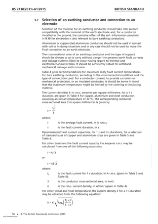
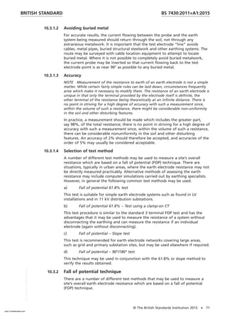
![The earth fault current can also be of such magnitude and duration as to cause an
excessive temperature rise in the conductors through which it flows, thereby
creating a fire hazard.
BS 7671:2008+A3 includes a number of protective measures which can be
applied for protection against earth faults. However, this standard only considers the
protective measure known as automatic disconnection of supply. This is the most
commonly utilised of the protective measures contained in BS 7671:2008+A3.
Furthermore, the others do not depend on earthing and have very limited
applications.
ADS is a protective measure in which:
a) basic protection is provided by basic insulation of live parts or by barriers or
enclosures; and
b) fault protection is provided by protective earthing, protective equipotential
bonding and automatic disconnection in case of a fault.
A brief summary of the requirements of BS 7671:2008+A3 for automatic
disconnection of supply is given in 6.2 to 6.11.
Where automatic disconnection of supply is applied, Class I and Class II
equipment may be used.
In designing the protective system of any installation, due account should be
taken of the need to ensure that periodic inspection, testing and maintenance
can be readily and safely undertaken.
6.2 Earthing of installations
Most installations are part of either a TN system or a TT system, and in both
types of installation the exposed-conductive-parts of all the electrical equipment
of an installation should be connected by means of circuit protective conductors
to the main earthing terminal. The earth fault loop impedance should be
sufficiently low for the protective device (fuse, circuit breaker, RCD) to operate
in the required time in the event of a fault to earth.
Class II equipment, whether metal encased or insulation encased, embodies in its
construction not only basic insulation but also supplementary or reinforced
insulation; exposed metalwork of such equipment should not be considered to
become live under fault conditions, i.e. is not considered to be an
exposed-conductive-part.
The various earthing systems are considered in 4.2.
6.3 Information to be provided on request
As necessary, the owner of an installation, the employer or a contractor should
determine from the electricity distributor the relevant information as described
in the ESQCR [1] and ESQCR (NI) [3]. The owner or his agent should satisfy
themselves that the characteristics of the earth fault current path, including any
part of that path provided by a supply undertaking, are suitable for operation
of the type of earth fault protection intended for use in the installation
concerned.
COMMENTARY ON 6.3
When it is intended to install standby supplies to operate in parallel with the
normal supply provided by a supply undertaking, the arrangements have to be
agreed with the distributor {see regulation 22(1)(d) of the ESQCR [1] and
Regulation 23(1)(d) of the ESQCR (NI) [3]}.
Regulation 28 of the ESQCR [1] and Regulation 29 of the ESQCR (NI) [3] require the
distributor to provide certain information as follows (the exact text here is taken
from the ESQCR [1]):
BRITISH STANDARD BS 7430:2011+A1:2015
© The British Standards Institution 2015 • 13
www.TeraStandard.com
--``,`,`,`,,,,`,,,,,,,`,,`,,```,-`-`,,`,,`,`,,`---](https://image.slidesharecdn.com/560446183-kz1o3nvhwcbs-7430-a1-2015-250126112157-f88d272d/85/EARTHING-SYSTEM-CALCULATION-WITH-EARTHIG-STRIP-SIZE-19-320.jpg)
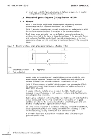
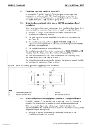
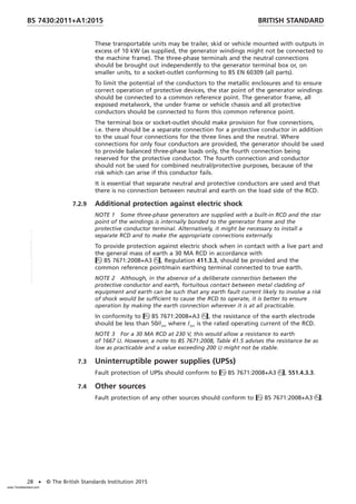
![Where an installation is supplied by more than one source of energy (e.g. a
supply from a distributor and a supply from a generating set), the earthing
system of the installation should be designed so that each source that can
operate independently of other sources and remain earthed if all the other
sources are not connected.
NOTE 3 There are many variations in system design and, for any particular
application, the precise method of earthing of each energy source is subject to the
recommendations of the equipment supplier and to the system parameters.
NOTE 4 Public low voltage distribution networks have to be directly earthed in
conformity to the current ESQCR (Regulations 7 to 10) [1] and ESQCR (NI) [3].
Since an installation connected to a distributors network might be expected to be
designed accordingly, direct earthing is also normally adopted for any generating set
which supplies such an installation.
Whenever it is intended that a private generating set be used to supply any part
of a consumer’s system normally supplied by a distributor, the distributor and
supplier should be consulted.
NOTE 5 The ESQCR [Regulation 22(1)(d)] [1] and ESQCR (NI) Regulation 23(1)(d)
[3] require that, where operation in parallel with a distributors network is intended,
the agreement of the distributor has to be obtained first, subject to Regulation 22(2)
{Regulation 23(2) in ESQCR (NI) [3]} for generators rated up to a total of 16 A per
phase.
7.2.2 References
The following ENA Engineering Recommendations should be consulted where
relevant:
• ER G59, Recommendations for the connection of embedded generating
plant to the Regional Electricity Companies’ distribution systems;
• ER G83, Recommendations For The Connection Of Small-Scale Embedded
Generators (Up To 16 A Per Phase) In Parallel With Public Low-Voltage
Distribution Networks;
• ER G84, Recommendations for the Connection of Mobile Generating Sets to
Public Distribution Networks.
NOTE ER G84 gives recommend working procedures for the connection of
small portable generating sets and larger mobile generating sets for the
purposes of providing a temporary supply to customers or for network support.
It addresses direct connections to the low voltage network and connections via a
step-up unit to the high voltage network.
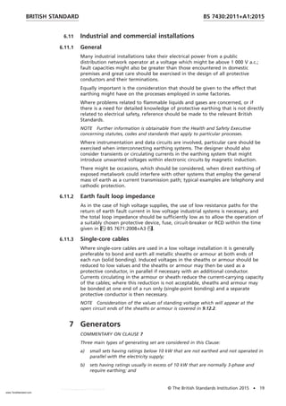
7.2.3 Generating sets having ratings above 10 kW
Generating sets with outputs above 10 kW are normally 3-phase; these types of
set may be permanently installed in buildings, enclosed in weatherproof and
sound attenuated enclosure, and vehicle or trolley mounted. It should not be
assumed that they will be provided with the generator windings connected to a
mounting frame.
An independent generator may be installed to supply construction sites
(BS 7671:2008, Section 704) or temporary electrical installations (BS 7671:2008,
Section 740) as an alternative to a distributor’s supply which is as yet
unavailable. Such installations though temporary should be robust and conform
to the requirements of BS 7671:2008, with a main earthing terminal provided
connected to earth, usually by an earth electrode.
BRITISH STANDARD BS 7430:2011+A1:2015
© The British Standards Institution 2015 • 23
www.TeraStandard.com
--``,`,`,`,,,,`,,,,,,,`,,`,,```,-`-`,,`,,`,`,,`---](https://image.slidesharecdn.com/560446183-kz1o3nvhwcbs-7430-a1-2015-250126112157-f88d272d/85/EARTHING-SYSTEM-CALCULATION-WITH-EARTHIG-STRIP-SIZE-29-320.jpg)
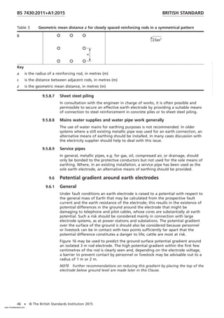
![8 Special installations
8.1 Temporary scaffolding and similar metallic structures
8.1.1 Metallic structures assembled by means of bolted joints or screw
clamps
NOTE 1 Where structures are assembled using bolted joints or screw clamps, a
multiplicity of such connections is likely to provide several paths of relatively low
resistance. Although such structures are not designed to be electrically continuous, it
is reasonable to assume that they have a low value of electrical resistance.
Whatever type of structural fastenings or footings in contact with the ground
are employed, and however a temporary structure may be fastened to a
permanent structure, it should not be assumed that a temporary metallic
structure is effectively earthed.
NOTE 2 Most erections of metallic scaffolding are the subject of statutory
regulations concerning construction work.
The distribution of electricity on construction sites should conform to BS 7375.
Except where it is necessary for lightning protection purposes (see 8.2),
scaffolding external to a structure should not be connected to the means of
earthing within the structure that is afforded by supply authorities.
Where scaffolding is erected against or around a structure which does not have
electrical services, and electrical equipment is not likely to be used for
construction work, electrical bonding for shock protection purposes may be
omitted.
Where protective conductors are required, they should be of copper and
protected against corrosion by a covering at least equivalent to the insulation of
a single non-sheathed cable, and should be routed to avoid damage from work
equipment and work activities. A conductor should be connected to scaffolding
by a corrosion-resistant clamp conforming to BS 951, and which is suitably
protected against mechanical damage.
For extensive scaffolding structures, where earthed, connections should be made
at points not more than 20 m apart laterally.
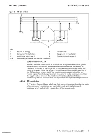
8.1.2 Structures forming part of precautions to avoid danger from live
overhead electric lines
COMMENTARY ON 8.1.2
The Health and Safety Executive publishes guidance on the dangers of live overhead
power lines, see Guidance Note GS6 Avoidance of Danger from Overhead Electrical
Lines [5].
Paragraph 20 b) of GS6 refers to the use of a tensioned wire fence as a high level
barrier, and notes that the electricity distributor has to be consulted about the
erection and earthing of the barrier.
8.2 Lightning protection
If scaffolding is associated with an existing structure which has an external
lightning protection system (LPS), it should be bonded to the earth termination
network and the air termination network of the LPS. Lightning protection
should otherwise be provided where indicated by risk assessment performed in
accordance with BS EN 62305-2.
BRITISH STANDARD BS 7430:2011+A1:2015
© The British Standards Institution 2015 • 29
www.TeraStandard.com
--``,`,`,`,,,,`,,,,,,,`,,`,,```,-`-`,,`,,`,`,,`---](https://image.slidesharecdn.com/560446183-kz1o3nvhwcbs-7430-a1-2015-250126112157-f88d272d/85/EARTHING-SYSTEM-CALCULATION-WITH-EARTHIG-STRIP-SIZE-35-320.jpg)
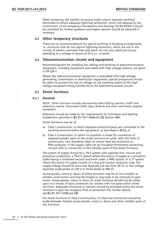
![For street furniture of class I construction, the characteristics of the supply
system, the characteristics of the earthing system, including consumer earthing
provisions, the material of the street furniture and any surface protection, and
that of the access panels, covers or doors together with whether they are
hinged or have to be lifted off to gain access should inform the designer’s risk
assessment as to whether they do or do not require any electrical connection.
In coming to a reasoned engineering judgement, note should be taken of the
recorded instances and future possibility of reversed polarity of the supply or
the loss of the neutral connection on the supply side of a TN-C-S system (for
example, it would be reasonable for small isolated metal doors of
non-conductive columns such as concrete columns, supplied from a PME
distribution system that conform to the ESQCR [1] and ESQCR (NI) [3], not
to be earthed).
In all cases, the distributor should be consulted before design work on new
street furniture is commenced to ascertain the type of system that will supply
the new installation.
8.5.2 Supply systems for street furniture
8.5.2.1 General
Street furniture may normally be fed from TN-S or TN-C-S systems.
8.5.2.2 TN-S systems
Street furniture may be fed from and protected by a TN-S system and in such
arrangements a supply cable with separate line, neutral and protective
conductors should be used. In Class I street furniture the wiring on the load side
of the protective device in the unit should consist of separate line, neutral and
circuit protective conductors. Exposed-conductive-parts of the item of street
furniture being supplied should be earthed by connecting them to the earthing
terminal within the equipment. The earthing terminal itself should be connected
to the supply protective conductor.
If an installation is all Class II, no protective conductor is required and the wiring
on the load side of the protective device should consist of line and neutral
conductors only.
It is recommended that a circuit supplying one or more items of Class II
equipment or a mixture of Class I and Class II should have a circuit protective
conductor run to and appropriately terminated at each point in wiring and at
each accessory.
8.5.2.3 TN-C-S systems
An alternative method of supplying and protecting street furniture that may be
used is by means of a TN-C-S system. In such cases a combined neutral and earth
conductor cable may normally be used at the source of supply (for example to
an individual lighting column or for larger installations a local supply authority
PME supply into a feeder pillar, with cables using separate line, neutral and
circuit protective conductors to feed individual items of street furniture as might
be used on footpaths, or to feed items of street furniture in the carriageway).
In the case of circuits feeding more than one item of street furniture, e.g. by
looping using a cable with separate line, neutral and protective conductors,
an earth electrode should be installed both at the point of supply and at the
last or penultimate unit and this electrode should be such as to make the
resistance to earth of the neutral at any point less than 20 Ω before the
connection of any circuit protective or bonding conductors to the neutral
terminal. If a single electrode produces a resistance of more than 20 Ω, other
earth electrodes equally spaced along the circuit should be installed.
BRITISH STANDARD BS 7430:2011+A1:2015
© The British Standards Institution 2015 • 31
www.TeraStandard.com
--``,`,`,`,,,,`,,,,,,,`,,`,,```,-`-`,,`,,`,`,,`---](https://image.slidesharecdn.com/560446183-kz1o3nvhwcbs-7430-a1-2015-250126112157-f88d272d/85/EARTHING-SYSTEM-CALCULATION-WITH-EARTHIG-STRIP-SIZE-37-320.jpg)
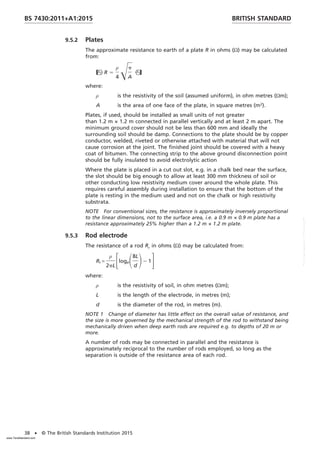
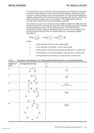
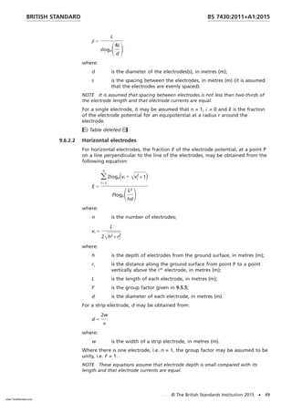
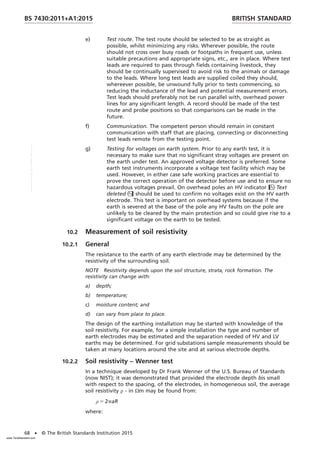
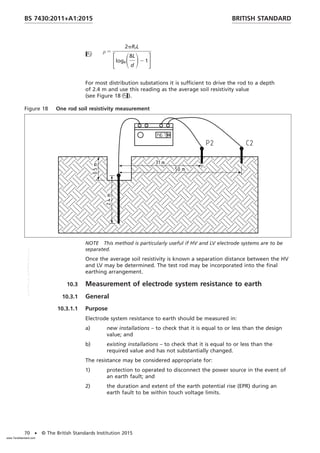
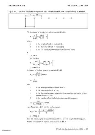
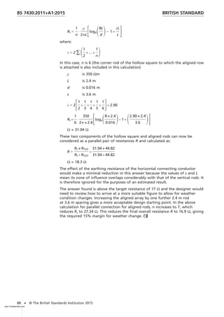
![ρ is the resistivity of soil, in ohm metres (Ωm);
ρc is the resistivity of the conducting material used for the backfill,
in ohm metres (Ωm);
L is the length of rod, in metres (m);
d is the diameter of the rod, in metres (m)
D is the diameter of the in-fill, in metres (m).
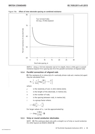
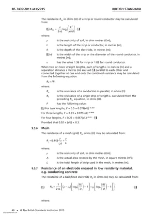
9.5.8 Miscellaneous electrodes
NOTE There are many configurations that can be set out under this heading, but a
few of those which one is most likely to try first in order to achieve the required
value are included especially when dealing with deep reinforced piles, etc.
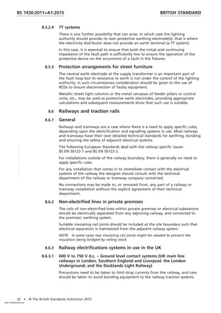
9.5.8.1 Three rods at the vertices of an equilateral triangle
The resistance Re in ohms (Ω) of three interconnected rods set out at the vertices
of an equilateral triangle [see Figure 15a)] of side s metres length may be
calculated from:
Re 5
1
3
·
ρ
2pL
FlogeS8L
d
D2 1+
2L
s
G
where:
ρ is the resistivity of soil, in ohm metres (Ωm);
L is the length of rod, in metres (m);
d is the diameter of rod, in metres (m);
s is the length of one side of the equilateral triangle, in metres (m).
Figure 15 Miscellaneous electrode configurations
a) Three rods at the vertices of an equilateral triangle b) Two strips set at right angles to each
other meeting at one corner
c) Three strips set at 120° meeting at the star point all
of equal length
d) Four strips set in a cruciform
e) Vertical electrodes arranged in a hollow square
BRITISH STANDARD BS 7430:2011+A1:2015
© The British Standards Institution 2015 • 41
www.TeraStandard.com
--``,`,`,`,,,,`,,,,,,,`,,`,,```,-`-`,,`,,`,`,,`---](https://image.slidesharecdn.com/560446183-kz1o3nvhwcbs-7430-a1-2015-250126112157-f88d272d/85/EARTHING-SYSTEM-CALCULATION-WITH-EARTHIG-STRIP-SIZE-47-320.jpg)
![9.5.8.2 Two equal length conductors set at right angles to each other,
meeting at one corner
The resistance RL in ohms (Ω) of two strips or round conductors of equal length
set at 90° with one corner touching [see Figure 15b)] may be calculated from:
RL 5
ρ
2pL
logeSL2
κhd
D
where:
ρ is the resistivity of soil, in ohm metres (Ωm);
L is the total length of strip or round conductor in metres (m);
h is the depth of burial in metres (m);
d is the width of the strip or the diameter of the round
conductor in metres (m);
κ has the value 1.21 for strip or 0.813 for round conductor.
9.5.8.3 Three equal length conductors set at 120°, meeting at the star point
The resistance RS in ohms (Ω) of three star arranged strips or round conductors
of equal length [see Figure 15c)] may be calculated from:
Rs 5
ρ
2pL
logeSL2
κhd
D
where:
ρ is the resistivity of soil, in ohm metres (Ωm);
L is the total length of strip or round conductor in metres (m);
h is the depth of burial in metres (m);
d is the width of the strip or the diameter of the round
conductor in metres (m);
κ has the value 0.734 for strip or 0.499 for round conductor.
9.5.8.4 Four equal length conductors set in a cruciform
The resistance Rcr in ohms (Ω) of four strips or round conductors of equal length
set out in a cruciform [see Figure 15d)] may be calculated from:
Rcr 5
ρ
2pL
logeSL2
κhd
D
where:
ρ is the resistivity of soil, in ohm metres (Ωm);
L is the total length of strip or round conductor in metres (m);
h is the depth of burial in metres (m);
d is the width of the strip or the diameter of the round
conductor in metres (m);
κ has the value 0.219 for strip or 0.133 for round conductor.
BRITISH STANDARD
BS 7430:2011+A1:2015
42 • © The British Standards Institution 2015
www.TeraStandard.com
--``,`,`,`,,,,`,,,,,,,`,,`,,```,-`-`,,`,,`,`,,`---](https://image.slidesharecdn.com/560446183-kz1o3nvhwcbs-7430-a1-2015-250126112157-f88d272d/85/EARTHING-SYSTEM-CALCULATION-WITH-EARTHIG-STRIP-SIZE-48-320.jpg)
![9.5.8.5 Vertical rods in a hollow square
The resistance RTOT of rods set out in a hollow square [see Figure 15e)] may
be calculated from:
RTOT = RrS1 + λα
N
D
where:
α 5
ρ
2pRrs
Rr is the resistance of one rod, in oms (Ω);
λ is the factor in Table 2;
ρ is the resistivity of soil, in ohm metres (Ωm);
s is the spacing of rods, in metres (m);
N is the number of rods used as electrodes (see the note to
Table 2).
Table 2 Factors for vertical electrodes arranged in a hollow square
Number of electrodes (n) along the
side of the square
Factor λ Number of electrodes (n) along the
side of the square
Factor λ
2 2.71 9 7.65
3 4.51 10 7.90
4 5.46 12 8.22
5 6.14 14 8.67
6 6.63 16 8.95
7 7.03 18 9.22
8 7.30 20 9.40
NOTE The number of electrodes N around the square is 4(n − 1).
NOTE Table 2 may also be used for electrodes arranged in a rectangle, where n
is given by n 5
N
4
+1 , where N is the total number of electrodes. Provided that the
length to width ratio of the rectangle does not exceed 2, the error will be smaller
than 6%.
9.5.8.6 Structural steelwork
Foundation metalwork in concrete may be used as a ready made and effective
earth electrode. The total electrode area formed by the underground metalwork
of large structure may often be used to provide an earth resistance lower then
that obtainable by other methods; overall values well below 1 Ω are obtainable.
It is important that consideration is given to the possibility of corrosion of the
metalwork reinforcement; the products of corrosion occupy a greater volume
than the original metal and cracking might occur. In particular, continuous earth
currents should be given attention; a possible source of such current might be
incompatibility with other buried metalwork, including other types of earth
electrode to which foundation metalwork may be bonded (see 9.6).
NOTE 1 It might be necessary to consider the need for cathodic protection.
BRITISH STANDARD BS 7430:2011+A1:2015
© The British Standards Institution 2015 • 43
www.TeraStandard.com
--``,`,`,`,,,,`,,,,,,,`,,`,,```,-`-`,,`,,`,`,,`---](https://image.slidesharecdn.com/560446183-kz1o3nvhwcbs-7430-a1-2015-250126112157-f88d272d/85/EARTHING-SYSTEM-CALCULATION-WITH-EARTHIG-STRIP-SIZE-49-320.jpg)
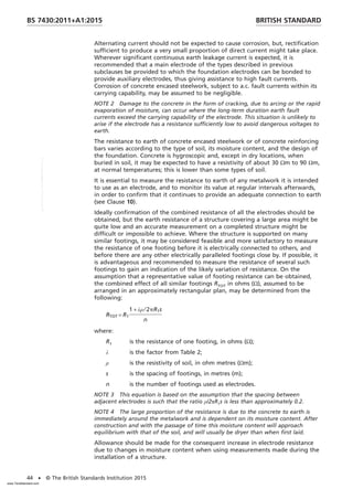
![Table 10 Minimum sizes of components for earth electrodes
Electrode type Cross-sectional area Diameter or thickness
mm2
mm
Copper strip 50 3
Hard drawn or annealed copper
rods or solid wires for driving or
laying in ground
50 8
Copper-clad or galvanized steel
rods (see notes) for harder
ground
153 14
Stranded copper 50 3 per strand
For copper-clad steel rods the core should be of a low carbon steel with a
tensile strength of approximately 600 N/mm2
and a quality not inferior to grade
S275 conforming to BS EN 10025. The cladding should be of 99.9% purity
electrolytic copper, molecularly bonded to the steel core. The radial thickness of
the copper should be not less than 0.25 mm.
Couplings for copper-clad steel rods should be made from copper-silicon alloy or
aluminium bronze alloy with a minimum copper content of 75%.
For galvanized steel rods, steel of grade S275 conforming to BS EN 10025 should
be used, the threads being cut before hot-dip galvanizing in accordance with
BS 729.
The current carrying capability of the type of joints used (especially bolted
joints) should also be taken into account. Reference should be made to
BS EN 50164-2 for minimum earthing conductor and earth electrode dimensions.
9.11 Selection of a material for an earth electrode or a buried
uninsulated earthing conductor
Although the material does not affect the earth resistance of an electrode, care
should be taken to select a material that is resistant to corrosion in the type of
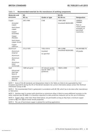
soil in which it will be used. Some recommended materials for the manufacture
of earthing components are listed in Table 11.
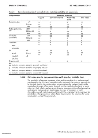
There are two aspects which should be considered regarding the corrosion
resistance of an earth electrode or an earthing conductor: compatibility with the
soil itself and possible galvanic effects when it is connected electrically to
neighbouring metalwork; the latter is most likely to come about when the
earthing system is bonded to exposed metal structural components.
Table 11 Recommended materials for the manufacture of earthing components
Materials and
processes
BS BS EN
BS no. Grade or type BS EN no. Designation
Ingots for cast components
Leaded gunmetal 1982:2008 CB490K, CB491K
Aluminium silicon
bronze
1400 AB3 [no equivalent
in EN 1982]
1982:2008 CB331G,
Aluminium alloy 1780-1:2002 EN AB-44000,
EN AB-42000
Cast iron 1561:1997
Malleable iron 1562:1997
Forgings and stampings (hot and cold formed)
BRITISH STANDARD BS 7430:2011+A1:2015
© The British Standards Institution 2015 • 63
www.TeraStandard.com
--``,`,`,`,,,,`,,,,,,,`,,`,,```,-`-`,,`,,`,`,,`---](https://image.slidesharecdn.com/560446183-kz1o3nvhwcbs-7430-a1-2015-250126112157-f88d272d/85/EARTHING-SYSTEM-CALCULATION-WITH-EARTHIG-STRIP-SIZE-69-320.jpg)
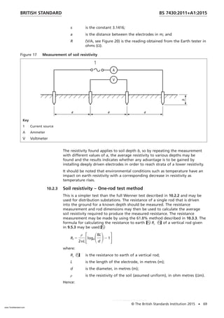
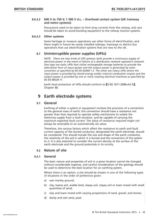
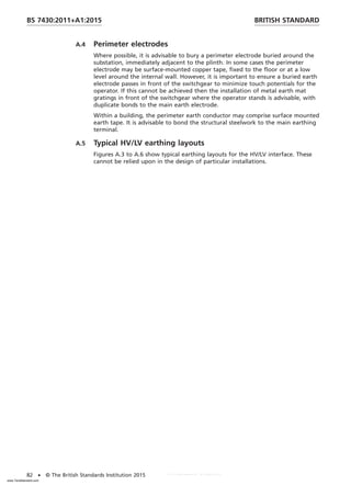
![Figure A.2 TN-S system with common HV equipment and LV neutral earth
U1 = U0, U2 = U1 = U0, and Uf = REIE
Key
1 Substation 2 LV installation
A.2 Legislation
The Electricity Supply Regulations (replaced by The Electricity Safety, Quality
and Continuity Regulations [1], [3]) required that where in a substation the
HV equipment earth and the LV neutral earth were common, that the resistance
to earth has to not exceed 1 Ω. For most substations this value was provided by
the un-insulated protective sheaths of the older types of cables in use and was
normally sufficient to lower the impedance of these cable sheaths to ensure
sufficiently low earth potential rise (EPR) for general combination of HV and LV
earth systems even with very high earth-fault current. However this simple
requirement is no longer adequate.
Regulation 8(2) of The ESQCR [1],[3] requires that in respect of any
high-voltage installation, the earthing has to be designed, installed and
maintained so as to prevent danger in any low-voltage network occurring as a
result of any fault in the high-voltage network. The advice in the Guidance on
the ESQCR [4] and the Guidance on the ESQCR (NI) [6] is:
Duty holders must ensure that persons are not at risk of danger from low
voltage networks due to the rise in potential of the earthing system caused
by the release of earth fault current from the high voltage system. In practice
duty holders will either interconnect the earthing conductors connected to
high voltage equipment and those connected to low voltage system where
the combined resistance to earth is very low or alternatively operate separate
earth electrodes in which case the effect of overlapping resistance areas
should be minimal.
The current advice of the Health and Safety Executive is that touch voltages
should not exceed curve the recommendations of BS EN 50522:2011, National
Annex NA.2.
A.3 Combined HV/LV earth resistance
BS EN 50522:2011 gives requirements for determining if the HV and LV Earth
nests can be connected together and to determine the combined HV/LV earth
resistance.
BRITISH STANDARD BS 7430:2011+A1:2015
© The British Standards Institution 2015 • 81
www.TeraStandard.com
--``,`,`,`,,,,`,,,,,,,`,,`,,```,-`-`,,`,,`,`,,`---](https://image.slidesharecdn.com/560446183-kz1o3nvhwcbs-7430-a1-2015-250126112157-f88d272d/85/EARTHING-SYSTEM-CALCULATION-WITH-EARTHIG-STRIP-SIZE-87-320.jpg)
![Bibliography
Standards publications
For dated references, only the edition cited applies. For undated references, the
latest edition of the referenced document (including any amendments) applies.
Text deleted
BS 7454/IEC 60909, Method for calculation of thermally permissible
short-circuit currents, taking into account non-adiabatic heating effects
Text deleted
BS EN 14505, Cathodic protection of complex structures
BS EN 88528-11, Reciprocating internal combustion engine driven alternating
current generating sets – Part 11: Rotary uninterruptible power systems –
Performance requirements and test methods
BS EN 50173 (all parts), Information technology – Generic cabling systems
BS EN 60335-1:2012+A11:2014, Household and similar electrical appliances
– Safety – Part 1: General requirements
BS EN 60601 (all parts), Medical electrical equipment
BS EN 61140/IEC 61140, Protection against electric shock – Common aspects for
installation and equipment
BS EN 62040-1-2, Uninterruptible power systems (UPS) – General and safety
requirements for UPS used in restricted access locations
Text deleted
PD 6484, Commentary on corrosion at bimetallic contacts and its alleviation
BS EN ISO 1460, Metallic coatings – Hot dip galvanized coatings on ferrous
materials – Gravimetric determination of the mass per unit area
BS EN ISO 1461:1999, Hot dip galvanized coatings on fabricated iron and steel
articles. Specifications and test methods
Other publications
[1] GREAT BRITAIN. Electricity Safety, Quality and Continuity
Regulations 2002 (incorporating any amendments).
[2] GREAT BRITAIN. The Electricity at Work Regulations 1989.
[3] NORTHERN IRELAND. Electricity Safety, Quality & Continuity Regulations
(Northern Ireland), 2012 1)
(incorporating any amendments).
[4] DTI, Guidance on Regulations. Guidance on the Electricity Safety, Quality
and Continuity Regulations 2002 2)
. URN 02/1544.
[5] HSE, Guidance Note GS6. Avoiding danger from overhead power lines. 2013.
[6] DEPARTMENT OF ENTERPRISE, TRADE AND INVESTMENT, NORTHERN
IRELAND. Guidance on the Electricity Safety, Quality and Continuity
Regulations (Northern Ireland) 2012. Belfast. December 2012.
1)
http://www.legislation.gov.uk/nisr/2012/381/made (Last accessed 27th
August 2015.)
2)
http://www.legislation.gov.uk/uksi/2002/2665/contents/made (Last accessed 27th
August
2015.)
BRITISH STANDARD BS 7430:2011+A1:2015
© The British Standards Institution 2015 • 89
www.TeraStandard.com
--``,`,`,`,,,,`,,,,,,,`,,`,,```,-`-`,,`,,`,`,,`---](https://image.slidesharecdn.com/560446183-kz1o3nvhwcbs-7430-a1-2015-250126112157-f88d272d/85/EARTHING-SYSTEM-CALCULATION-WITH-EARTHIG-STRIP-SIZE-95-320.jpg)