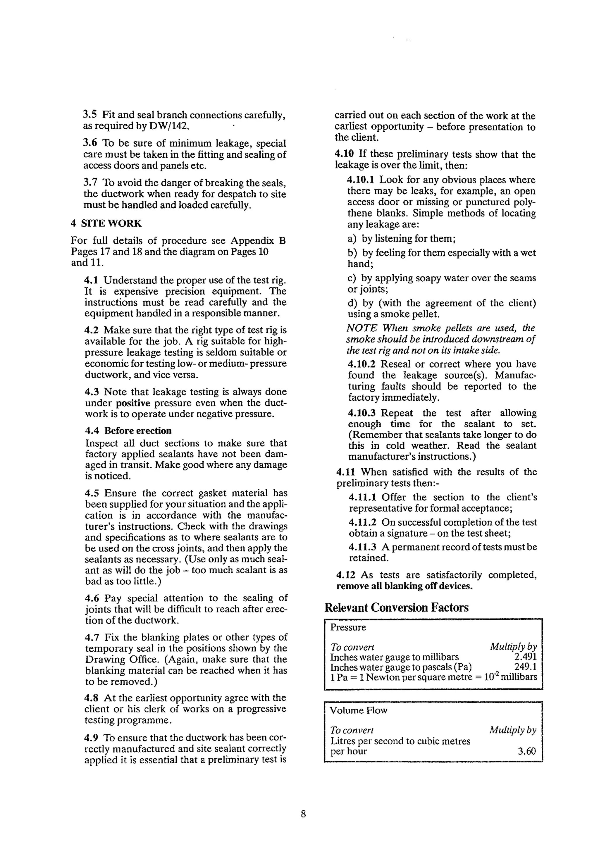
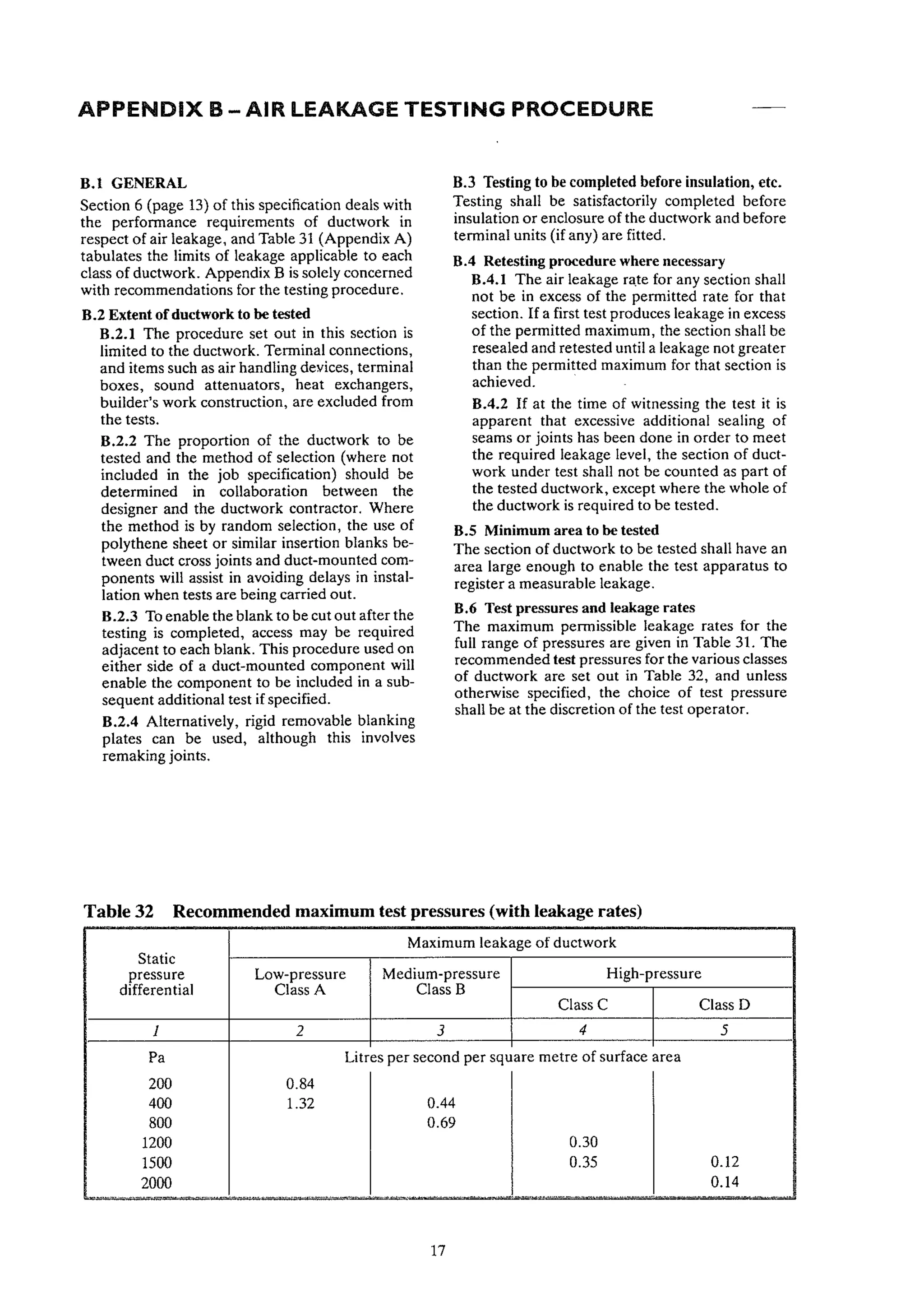
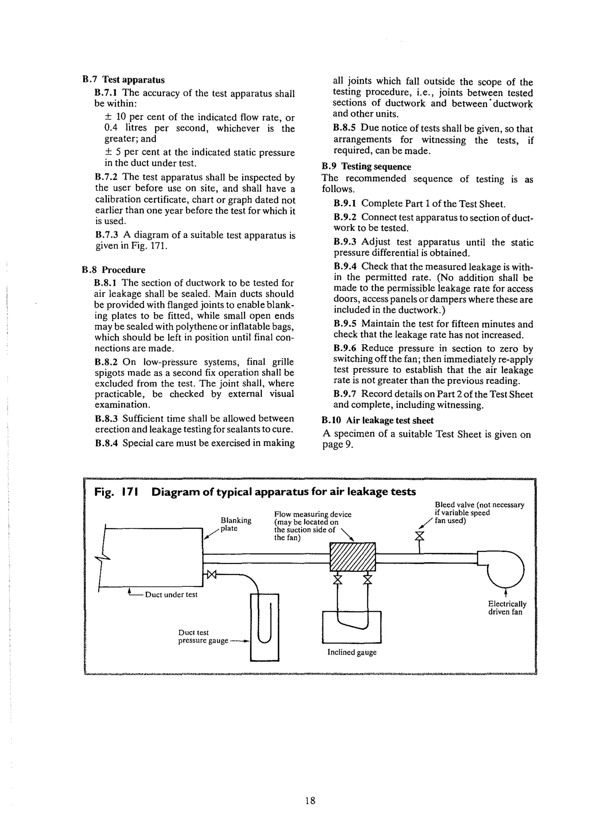
CVSfB
I (57.91 I Ih I (A3ul
143
A practical guide to
DUCTWORK LEAKAGE TESTING
Based on the requirements of DW/142 specification for sheet metal ductwork
COPYRIGHT © 1983 by the
Heating and Ventilating
Contractors' Association
All rights reserved
HEATING AND VENTILATING
CONTRACTORS' ASSOCIATION
Esca House, 34 Palace Court,
London W2 4JG
Telephone: 071 229 2488
Fax: 071 727 9268
Obtainable from: HVCA Publications,
Old Mansion House, Eamont Bridge, Penrith,
Cumbria, CAIO 2BX
Telephone: (0768) 64771 Fax: (0768) 67138
Price: £9 (including inland postage)
Overseas: Surface mail £10.50 Air mail £11.00
3
Contents
Part One
Acknowledgements .
Preface .
Financial Caution .
Practical Guide to leakage testing .
Example ofcomplete test sheet .
Hints on leakage testing .
Part Two
Air leakage from ductwork
Nomogram converting area basis to percentage of airflow .
Air leakage testing procedure .
ACKNOWLEDGEMENTS
The HVCA records its appreciation and thanks to the persons and
organisations who have freely contributed to this work, and in
particular to the members of the Drafting Panel.
DW/143 Drafting Panel
J. H. G. Gardner (Chairman)
K. Angood
P. Doyle
K. Wheatley
K. Waldron
H. Brocklehurst
H. Brierley
J. M. Paynton (Former Secretary, Duct Work Group)
R. J. Miller (Secretary, Duct Work Group)
4
Page
4
5
6
7-8
9
10-11
Page
13-15
16
17-18
PREFACE
Ductwork Specification DW/142, published by the HVCA in 1982, provides
for the first time in a long series ofsuch publications for leakage limits over the
whole range of air pressures covered by the specification and (where
required) a test procedure to establish conformity.
Although leakage testing of high-pressure ductwork is mandatory in
DW/142 (as was the case in previous ductwork specifications issued by
HVCA) the leakage testing of ductwork designed to operate at low and
medium pressures is required only where so specified in individual job
specifications.
With the introduction offour pressure classifications in DWI142 it is hoped
that the designer, having selectional control ofconstructional standards, will
find leakage testing an unnecessary contract expense with regard to low and
medium pressure ductwork. However, it is possible that initially the advent of
more stringent constructional requirements may be followed by an increased
demand by clients and specifiers for the testing oflow-and medium- pressure
ductwork and this booklet has been prepared in order to assist ductwork
contractors to minimise the cost ofthis unfamiliar operation.
It will be noted that the leakage limits specified in Appendix A of DW/142
are expressed in litres per second persquare metre ofduct area. It is however
possible that some ductwork specifications will still quote leakage limits as a
percentage of air flow. In order that the area basis can be converted to a
percentage equivalent a nomogram from DW/142 has been reproduced in
this booklet on Page 16.
Ductwork contractors faced with a job calling for leakage testing should
take this requirement very seriously and satisfy themselves as the job
progresses that the required leakage rate or rates are within the limits set by
the designer or the client. The cost of making good an installation that has
been found on completion to have failed in this respect can be very expensive
indeed.
DW/142 specifies leakage limits for the ductwork alone, not for the
complete air distribution system. This is because the ductwork contractor has
no control over the leakage characteristics of the various components which
go to make up the whole of the air distribution system. Where a job
specification calls for a leakage limit for the whole system, it will be for the
designer or client to ensure that the leakage rates of the components are also
within the required limits.
J. H. G. Gardner,
Chairman, Executive Committee,
Duct Work Group, 1982/83.
5
FINANCIAL CAUTION
As highlighted in the Prefaces ofboth this document and DWI142 not
enough emphasis can be placed on the fact that the much tighter ductwork
constructional standards brought about by the general acceptance of
DW/142, virtually negates the requirement for leakage testing, except for the
high pressure classes C & D.
It is essential to realise that except where it is mandatory this document is
not an endorsement ofthe routine testing ofducts but purely a guide to
outline the procedures, necessary for testing ducts for conformity with air
leakage limits set forth in a designer's specification.
When proper methods ofassembly and sealing ofducts are used a visual
inspection will ordinarily suffice for verification ofwell engineered
reasonably air right construction.
WHERE NOTMANDATORY, DUCTLEAKAGE TESTING IS
GENERALLYAN UNJUSTIFIED SUBSTANTIAL EXPENSE.
6
Part One - A practical guide tel ductwork
leakage testing
I GENERAL
With regard to air leakage, the responsibility for
ensuring the achievement of a satisfactory job is
divided between the Drawing Office, the Factory
and the Site Erection Operatives. It is essential
that there is full co-operation between them.
2 THE DRAWING OFFICE
The drawing office must:
2.1 Establish with the client or his represent-
atives the class of ductwork called for in the
job specification, i.e.:
Class A: up to 500 Pa positive
Class B: up to 1000 Pa positive
Class C: up to 2000 Pa positive
Class D: up to 2500 Pa positive
2.2 Establish with the client or his represent-
ative that the required leakage rate or rates are
for the ductwork alone i.e. excluding dampers,
fire dampers, air handling units, fans, heater
batteries, silencers, terminal boxes, etc.
Additionally, establish the type of gasket
material required in relation to the pressure
class/velocity of the system.
Note:- Specific gasket material may be re-
quired in locations such as clean rooms,
hospitals etc.
H a leakage limit is laid down for the whole
system, it will be for the client or the designer
to ensure that the leakage characteristics of
the components are acceptable.
2.3 Agree with the client or designer the test
pressure for each section of the installation.
(Note that whilst duct construction
specification is related to the highest test class
ofthe duct installation it is important that each
duct test zone should only be tested to a
pressure to cover the mean working pressure of
that particularsection ofducting - see A.2.5(b).
2.4 Decide on the best way to isolate the
installation into test zones. When doing so, the
drawing office should bear in mind the test
pressures called for, the allowable air losses,
the work sequence on site and the capacity of
the test equipment.
7
2.5 Arrange for the supply ofsuitable blanking
medium, e.g. heavy-duty polythene sheet.
2.6 Make sure that all test points and blanking
devices can be reached with the minimum of
difficulty after the ductwork has been installed.
2.7 To ensure that a reading can be obtained,
plan test sections to have a permitted loss of
approximately 25 per cent less than the total
volume generated by the test rig at the pres-
sure required for each section.
2.8 Provide the erectors with details of the
test zones, duct operating pressures and test
pressures; and indicate the nature of the
blanking devices, gasket material and sealant
to be used.
2.9 Prepare test sheets giving the information
called for on the sample test sheet shown on
page 9.
This information should indicate the test
content, the surface area of the ductwork to be
tested, and the permitted loss for each section
to be tested (this loss is to be expressed in litres
per second per square metre ofthe ductwork).
3 THE FACTORY
3.1 Ductwork specification DW/142 requires
the sealing of more joints than was the case in
previous specifications. Care must therefore
be taken to make components with a good fit,
and to use only enough sealant to make a
satisfactory joint. A poor fit cannot be
remedied by the use of more sealant - it will
not work.
3.2 Seal all longitudinal seams, laps, cross
joints, rivets and duct penetrations generally,
in accordance with the requirements of
DW/142.
3.3 Make sure that sealant is properly applied
to the ends of all lock forms and other types of
longitudinal seam, and to the corners and
junctions between those seams and the cross
joints.
3.4 Take special care to have as small a clear-
ance as possible where there are penetrations
of the duct, as for example, damper spindles.
Pressure
Relevant Conversion Factors
To convert Multiply by
Inches water gauge to millibars 2.491
Inches water gauge to pascals (Pa) 249.1
I Pa =1Newton per square metre = 10,2 millibars
carried out on each section of the work at the
earliest opportunity - before presentation to
the client.
4.10 If these preliminary tests show that the
leakage is over the limit, then:
4.10.1 Look for any obvious places where
there may be leaks, for example, an open
access door or missing or punctured poly-
thene blanks. Simple methods of locating
any leakage are:
a) by listening for them;
b) by feeling for them especially with a wet
hand;
c) by applying soapy water over the seams
or joints;
d) by (with the agreement of the client)
using a smoke pellet.
NOTE When smoke pellets are used, the
smoke should be introduced downstream of
the test rig and not on its intake side.
4.10.2 Reseal or correct where you have
found the leakage source(s). Manufac-
turing faults should be reported to the
factory immediately.
4.10.3 Repeat the test after allowing
enough time for the sealant to set.
(Remember that sealants take longer to do
this in cold weather. Read the sealant
manufacturer's instructions.)
4.11 When satisfied with the results of the
preliminary tests then:-
4.11.1 Offer the section to the client's
representative for formal acceptance;
4.11.2 On successful completion ofthe test
obtain a signature - on the test sheet;
4.11.3 A permanent record oftests must be
retained.
4.12 As tests are satisfactorily completed,
remove all blanking olT devices.
3.60
Multiply by
To convert
Litres per second to cubic metres
per hour
Volume Flow
3.5 Fit and seal branch connections carefully,
as required by DW/142.
3.6 To be sure of minimum leakage, special
care must be taken in the fitting and sealing of
access doors and panels etc.
3.7 To avoid the danger of breaking the seals,
the ductwork when ready for despatch to site
must be handled and loaded carefully.
4 SITE WORK
For full details of procedure see Appendix B
Pages 17 and 18 and the diagram on Pages 10
and II.
4.1 Understand the proper use of the test rig.
It is expensive precision equipment. The
instructions must be read carefully and the
equipment handled in a responsible manner.
4.2 Make sure that the right type of test rig is
available for the job. A rig suitable for high-
pressure leakage testing is seldom suitable or
economic for testing low- or medium- pressure
ductwork, and vice versa.
4.3 Note that leakage testing is always done
under positive pressure even when the duct-
work is to operate under negative pressure.
4.4 Before erection
Inspect all duct sections to make sure that
factory applied sealants have not been dam-
aged in transit. Make good where any damage
is noticed.
4.5 Ensure the correct gasket material has
been supplied for your situation and the appli-
cation is in accordance with the manufac-
turer's instructions. Check with the drawings
and specifications as to where sealants are to
be used on the cross joints, and then apply the
sealants as necessary. (Use only as much seal-
ant as will do the job - too much sealant is as
bad as too little.)
4.6 Pay special attention to the sealing of
joints that will be difficult to reach after erec-
tion of the ductwork.
4.7 Fix the blanking plates or other types of
temporary seal in the positions shown by the
Drawing Office. (Again, make sure that the
blanking material can be reached when it has
to be removed.)
4.8 At the earliest opportunity agree with the
client or his clerk of works on a progressive
testing programme.
4.9 To ensure that the ductwork has been cor-
rectly manufactured and site sealant correctly
applied it is essential that a preliminary test is
8
a con1pleted test sheet
Based on dllldwod{ shownn oun page 10 and 11
Test No .
General N.ew +It>~ Pt'Ciecl
Name of job
Building Ref. ·wiM~···%iit··i~' .
.....................................................................................................................
Part 1- Physical details
a Section of ductwork to be tested ..~.. ~~.. ~ .:s.~ul..~ .
b Drawing Number , .:?:c:>i~~.1.~~ .
c Pressure Classification Oass B. (PROVIDED BY DESIGNERS)
d Test static pressure :::::::::~::~::.::::::::::::::::::::::::::::~~~~~~~~:~~~~:~~~:~~:~;~~:3~~
e Leakage factor S?:#.J!~/~I.~f (I'R?".'.~f.T~!~~~31~~.'.2.l
f Surface area of duct under test ~~ ~ ~ ~~.C?~.~~~.l!~~~9!".~~~~??:'~
g Maximum permitted leakage @y:.,~)~~: (5?B':':~.1?B:.~~TIPL:.ll<':' .•.~D.O
Part 2 - Test particulars
a Duct static pressure reading ~ ~~ ~~~~~'::.~~~~.~~~.~~.~!c:~
b Type of flow measuring device ~.. ~ ~ .r''5 (~??!~TE.~.'!f!'.~~~~ Y!:I:E!
c Range of measurement of flow measuring device Q..~ ~..~/~~.: .(~~~.R'.G.M.~~(~~~~!
d Reading of flow measuring device ~~.. ~ (I'R0 ~IG!
'2D 5 ~~ 1-r:::.1u (DERIVED FROM CHARTSUPPLIED wm-t RIG USING "d")
e Interpreted air flow leakage rate : ; <:-?Y.I,.!••.•(~~t:1.~.~I.~~.~~.~!~.~~.~~?~ ~I.~~:~ .
f Duration of test (normally 15 miuutes) IS ~
Date of test ...?:.~.'..~?.... Carried out ~~.::~:::::.::::::.... ~~;~~~~~~.~~.~::kl.~
Width and depth
Periphery Length Area
or diameter
millimetres millimetres metres square metres
800 x 750 3100 17.550 54.405
600 x 650 2500 5.570 13.925
300 x 300 1200 1.200 1.440
305 dia. 958 7.000 6.706
250 dia. 785 4.500 3.533
TOTAL 80.009
9
Hints on Ductwork Leakage Testing
305 dia.
250 dia.---~
600 x 650
800 x 750
475
Take special care
with inaccessible
joints
4595
500
300 x300 ---Jt-t'J..::::.llj
FLEX
Keep length to a minimum
and make sure that both
end connections are
correctly sealed and that
the flexible duct itself
has no leaks.
In order to avoid
incorrect readings
of duct pressure
the tube from the
vertical manometer
should be connected
directly to the
ductwork under test.
TEST APPARATUS
Site on firm level base and
ensure gauges are topped up
with correct fluid and
zeroed prior to
commencing test.
Fit correct flow measuring
device.
Inclined manometer to
read leakage rate
SEQUENCE OF TEST
1. Prepare test sheet.
2. Connect and adjust test apparatus to correct pressure.
3. Read off leakage rate.
4. Reseal if necessary (allow time to cure).
5. Maintain test for 15 mins.
6. Switch off and allow to zero.
7. Reapply test pressure and check reading.
8. Record details on test sheet and obtain signature.
WARNING
Take care not to over pt"essurise
system under test
10
The dimensions on this ductwork are used in an example on page 9
5925
800 x750
700
50
Blank off all open
ends with polythene
carefully taped into
position to avoid leaks.
Remember to blank
instrument tappings
and test holes.
4175
rtical manometer to
d duct pressure Blank at convenient
place with access
for ease of removal
800 x 750
HOW TO FIND LEAKS
1. Look - particularly at blanks, access openings
and difficult joints.
2. Listen - with test apparatus running, leaks
should be audible.
3. Feel- running your hand (particularly if wet)
over joints can help to locate leaks.
4. Soap and Water- paint over joints and look for bubbles
5. Smoke Pellet-placed inside ductwork (obtain permission for use)
DRG No. 20433112
11
Hints on Ductwork Leakage Testing The dimensions on this ductwork are used in an example on page 9
I~~~ ~ Take special care
/
~ with 1""""lbl,
.------ joints
r-..... aoo'750
y /
~
250dia.
i 250dl,j--
~
~
---.1J!Q
/ ,/
~~ 600 x650
~
I~
j ~
BOOx 750
==- ~305dl'. I 3500
A-
~
~
~  250 dia,'::::: - V ~
t+ ~ 250 dia.
./
,::::, "- ,
F'1 / I L'f' r
300,300 -
~
t
111
-
~
I~./ V
""
;
305di~ LJJ V
/ ~ ~~
FLEX
~459S
/
Keep length to a minimum
~ 7450
and make sure Ihal both 475
cnd connections are
correctly sealed and that
I
Blank off all open
the flexible duct itself
ends with polylhene
has no leaks. carefully taped into
position to avoid leaks.
~
Remember to blank
In order to avoid instrument tappings
incorrect readings
TEST APPARATUS and test holes.
ofduct pressure ~
/
Site on firm level base and
the tube from the
ensure gauges are lopped up
vertical manomeler
with correct fluid and
should be connected
- zeroed prior to
directly to the
commencing test.
ductwork under test.
Fit correct flow measuring
p device.
~ ::..----
~
~~V ~ i~ BI"k" 'O"~---- 0
I~
,Yertical manometer to
~el!d duct pressure
PI"OWlth""'~~
.t for ease of removal
Inclined manometer to , 800 x750
read leakage rate
............
SEQUENCE OF TEST HOW TO FIND LEAKS
I. Prepare test sheet. 1. Look - particularly at blanks, access openings
2. Connect and adjust lest apparatus 10 correct pressure. and difficult joints.
3. Read off leakage rate. 2. Lislen - with test apparatus running, leaks
4. Reseal if necessary (allow time to cure). should be audible.
5. Maintain test for 15 mins.
WARNING
3. Feel- running your hand (particularly if wet)
6. Switch offand allow to zero. over joints can help to locate leaks.
7. Reapply test pressure and check reading. Take care not to over pressurise 4. Soap and Water- paint over joints and look for bubbles
8. Record details on test sheet and obtain signature. system under test 5. Smoke Pellet- placed inside ductwork (obtain permission for use)
DRG No. 20433/12
10 11
Part Two
This section is predominantly extracted from DW/142 - Specification for Sheet Metal Ductwork, and for ease
of reference the numbering as in DW/142 has been retained. The leakage limits for EUROVENT classifi-
cations A, Band C, as set out in their document 2/2 (Air Leakage in Ductwork) have been adopted for the low
pressure, medium pressure and high pressure Class C classifications. EUROVENT document 2/2 has no
standard for a leakage class equivalent to our Class D and therefore the leakage limits for high pressure
ductwork used in DW/141 (the predecessor to DW/142) have been retained.
(5 AIR LEAKAGE STANDARDS
6.1 Limits for each pressure class
Permitted air leakage is related to four standards
of airtightness, as set out in Table 2.
6.2 Compatibility with EUROVENT
The leakage factors used in Table 2 for Classes A,
Band C are the same as those used for the classes
similarly designated in the Eurovent Document
2/2 (Air Leakage in Ductwork).
6.3 Leakage at various pressures; and other
relationships
Applying the limits specified in Table 2,
Appendix A (Table 31) sets out the permitted
leakage at each of a series of pressures up to the
maximum for each class. Included in that
appendix is a graphical presentation of the
pressure/leakage relationship; and also charts
from which may be determined leakage as a per-
centage of airflow for classes A, B or C.
Appendix A also gives details of the basis for the
leakage limits specfied in Table 2.
6.4 Testing for air leakage
All ductwork operating at pressures classified in
this specification as 'high pressure' shall be tested
to establish conformity with the relevant leakage
limits'set out in Table 2.
Testing for leakage of ductwork within the low
and medium ranges of pressure in this specifica-
tion will not form part of the ductwork contract
unless this requirement is set out in the job speci-
fication - see also Note (2) on page 1 ofDW 142.
Table 2 Air Leakage Limits
Air leakage Leakage limit
J 2
Iitres per second per square
metre of duct surface area
Low-pressure- 0.027 x p'.65
Class A
Medium-pressure- 0.009 x pO.65
Class B
High-pressure- 0.003 X po."
Class C
High-pressure- 0.001 x p"'"
Class D
where p IS the differential pressure In pascals
APPENDIX A - AIR LEAKAGE FROM DUCTWORK
A.I GENERAL CONSIDERATIONS
A.I.I Leakage points in ductwork
Air leakage in installed ductwork occurs almost
entirely at the longitudinal seams and the cross
joints, particularly at the corners, and at the
intersection of the seams and cross joints.
A.I.2 Leakage related to duct area
In practice, leakage can be taken as proportional
to the surface area of the ductwork, whether
rectangular or circular, even though there may be
considerable variation in different sections of a
complete system because of the changing sizes of
the ducts and the number and variety of the fit-
tings. The surface area is easily calculable as part
of the design procedure.
13
A.I.3 Pressure/leakage relationship
For a given pressure, the leakage through an
orifice of a given area will vary according to its
shape. With installed ductwork, the leakage
orifices are of differing shapes, so a precise value
cannot be given to the pressure/leakage relation-
ship. However, Swedish tests on a variety of con-
structions have shown that for ductwork oper-
ating within the range covered in this specifi-
cation, leakage can be taken as proportional to
pressure to the power of 0.65. (This value has
been adopted by EUROVENT in preparing their
Document 2/2 - Air Leakage in Ductwork - see
Appendix L - and has also been adopted in this
specification (see Table 2) and has been applied
in Table 31.
A.2 LEAKAGE LIMITS - RELATIONSHIPS
A.2.t Limits for each pressure class
Applying the values given in Table 2 (page 13).
the permitted leakage at each of a series of pres-
sures up to the maximum for each class is set out
in Table 31.
A.2.2 Graphical presentation
The pressure/leakage relationships given In
Table 31 are expressed graphically in Fig. 169.
A.2.3 Leakage as a percentage of airflow
As air leakage is related to surface area of the
ductwork, it cannot in advance of the detailed
calculations be expressed as a percentage of total
airflow, nor will a percentage loss be acceptable
as a standard of performance. However, applica-
tion of the leakage limits to a variety of ductwork
systems indicates that under oparating conditions
air losses will usually be within 6 per cent of total
airflow for the low-pressure class and 3 per cent
for the medium-pressure class. For the high-
pressure class, air loss is likely to be between 2
and 0.5 per cent, according to which leakage limit
is applied.
A.2.4 Special cases
The percentages mentioned in A.2.3 apply to
normal ratios of duct area to airflow; but where
the ratio is high (e.g. long runs of small ducts), it
may be necessary for the designer to specify a
higher standard of airtightness in order to keep
the actual leakage within an acceptable limit.
A.2.5 Designer's required calculations
Designers will be concerned with the total loss of
air through leakage which must be allowed for
the ductwork, and will need to:
(a) calculate the pressure class;
(b) calculate the surface area and estimate
the mean system pressure difference for
the ductwork system (or part ofsystem);
Definition of mean pressure
Pm = PI + P2, where:-
2
Pm = mean or average pressure.
P I = operating pressure at the beginning of the
ductwork system or part of system.
P2 = operating pressure at the end of the duct-
work system or part of system.
IT IS RECOMMENDED THAT MAXIMUM
TEST PRESSURES AND LEAKAGE RATES
SHOWN IN TABLE 32, PAGE /7, BE
ADOPTED.
(c) calculate the total leakage using the appro-
priate rate from Table 31.
14
Alternatively, the designer may:
(d) decide on the maximum total leakage that
he can accept;
(e) calculate the surface area and estimate the
mean system pressure difference for the
ductwork system (or part of system) and
from these determine the required pres-
sure class.
A.2.6 Leakage of complete system
DW/142 deals only with the ductwork. The leak-
age characteristics of plant items and accessories
are not within the control of the ductwork con-
tractor, and therefore any leakage limits and leak-
age testing called for under DW/142 shall be
understood to apply only to the ductwork itself.
Table 31 Air leakage rates
Static Maximum leakage of ductwork
pressure Low-pressure Med-prcssure High-pressure
differential Class A Class B Class C I Class D
J 2 3 4 I 5
Pa
Litres per second per square metre of surface area
100 0.54 0.18
200 0.84 0.28
300 1.10 0.37
400 1.32 0.44
500 1.53 0.51
600 0.58 0.19
700 0.64 0.21
800 0.69 0.23
9ml 0.75 0.25
10m) 0.80 0.27
IHXI 0.29 0.10
1200 0.30 0.10
1300 0.32 0.11
14(XI 0.33 0.11
15m) 0.35 0.12
1600 0.36 0.12
17m) 11.38 0.13
1800 0.39 0.13
1900 0.40 0.14
2000 0.42 0.14
2100 0.14
2200 0.15
23ml 0.15
2400 0.16
2500 0.16
Fig. 169 Permitted leakage at various pressures
(a) LOW & MEDIUM PRESSURE CLASSES - LEAKAGE LIMITS
1::
~
6l 1.5
~
b 1.25
e
~
0" 1.0
"'
..
ill.
""
g0.75
~
"'
..
"
c. 0.5
~
() IIKl 21Xl 31Ml -lOO son 600 7110 XOO t)O(l
Pressure difference in pascals
11l()O
'"
~
'"
~ 0.40
't:
=
"'
~ 0.35
""
~
~IU()
~
'"
&(1.25
"'
..
ill. ,
"C ILO
=
o
~
:: lJ.IS
.5
~(UIS
.!.'i
3
(b) HIGH PRESSURE CLASSES - LEAKAGE LIMITS
() }50 500 750 1000 12;i(J 1500 1750
Pressure difference in pascals
15
200ll 25(}()
Fig. 170 Leakage as percentage of airflow
1000
f-- ..- 600
1000
/' 600
600 1-- .. .-
/'
200 600 2000
/' ~
l-
V
'00
/'
100
1000 200
'00
60
200 6001-
60 .
,..e.- 100
I- 400 -- ,
80
40- b"L.- .. ~
100
60
80 V /'
20 60
200
~
V ./
l/
-
If V
40-
/'
10
100
f.:-- --
80 20
,
20 60
6
- . 10
, 40
V
10
br' I ./
, 1
2 6
20
Y
l/
j,.L
I
4
lO L
0
,
"
, , , ! I, t ,
"
< 200 '00 600 800 1000 2000
" ~
S 5
u u
LEAKAGE(Us) MEAN DIFFERENTIAL PRESSURE (Pal
Examples of use ofcharts
1--
V V
1/1/
1/ v:V 1/
40
- ~
2O!?L- V 1/ 1/
1/1/ I i/
101~1//V
1/
-,. .
6
,
21-/
....
j'/ +
1/ I
/ 1 I
1 I
CLASS A !
, , I! ! I, ! , ,
2 3 4 5 6 I , 10
CLASS 8
, ! I , , , , , '
1 2 3 4 5 6 ,
CLASSC ! !
, ! ! !
.5 1 2 3 ,
PERCENTAGE lEAKAGE
Mean differential pressure .
Duct area .
Airflow .
Maximum permitted leakage
Percentage of airflow .
Based on charts prepared by EUROVENT.
reproduced by kind permission.
Example I
Class A
320Pa
80m2
2 m3/s
Calculated
91.8
4.58
16
Example 2
ClassB
800Pa
200m2
6m3/s
Chart Calculated Chart
reading reading
92 138.8 139
4.6 2.31 2.3
APPENDIX B - AIR LEAKAGE TESTING PROCEDURE
B.l GENERAL
Section 6 (page 13) of this specification deals with
the performance requirements of ductwork in
respect of air leakage, and Table 31 (Appendix A)
tabulates the limits of leakage applicable to each
class of ductwork. Appendix B is solely concerned
with recommendations for the testing procedure.
B.2 Extent ofductwork to be tested
B.2.1 The procedure set out in this section is
limited to the ductwork. Terminal connections,
and items such as air handling deYices, terminal
boxes, sound attenuators, heat exchangers,
builder's work construction, are excluded from
the tests.
B.2.2 The proportion of the ductwork to be
tested and the method of selection (where not
included in the job specification) should be
determined in collaboration between the
designer and the ductwork contractor. Where
the method is by random selection, the use of
polythene sheet or similar insertion blanks be-
tween duct cross joints and duct-mounted com-
ponents will assist in avoiding delays in instal-
lation when tests are being carried out.
B.2.3 To enable the blank to be cut out after the
testing is completed, access may be required
adjacent to each blank. This procedure used on
either side of a duct-mounted component will
enable the component to be included in a sub-
sequent additional test if specified.
B.2.4 Alternatively, rigid removable blanking
plates can be used, although this involves
remaking joints.
B.3 Testing to be completed before insulation, etc.
Testing shall be satisfactorily completed before
insulation or enclosure of the ductwork and before
terminal units (if any) are fitted.
B.4 Retesting procedure where necessary
B.4.1 The air leakage ra.te for any section shall
not be in excess of the permitted rate for that
section. If a first test produces leakage in excess
of the permitted maximum, the section shall be
resealed and retested until a leakage not greater
than the permitted maximum for that section is
achieved.
B.4.2 If at the time of witnessing the test it is
apparent that excessive additional sealing of
seams or joints has been done in order to meet
the required leakage level, the section of duct-
work under test shall not be counted as part of
the tested ductwork, except where the whole of
the ductwork is required to be tested.
B.S Minimum area to be tested
The section of ductwork to be tested shall have an
area large enough to enable the test apparatus to
register a measurable leakage.
8.6 Test pressures and leakage rates
The maximum pennissible leakage rates for the
full range of pressures are given in Table 31. The
recommended test pressures for the various classes
of ductwork are set out in Table 32, and unless
otherwise specified, the choice of test pressure
shall be at the discretion of the test operator.
Table 32 Recommended maximum test pressures (with leakage rates)
Static
Maximum leakage of ductwork
pressure Low-pressure Medium-pressure High-pressure
differential Class A Class B
Class C Class D
J 2 3 4 5
Pa Litres per second per square metre of surface area
200 0.84
400 1.32 0.44
800 0.69
1200 0.30
1500 0.35 0.12
2000 0.14
-- .. ~ '" . ..,""'........ .... -
17
B.7 Test apparatus
B.7.1 The accuracy of the test apparatus shall
be within:
± 10 per cent of the indicated flow rate, or
0.4 litres per second, whichever is the
greater; and
± 5 per cent at the indicated static pressure
in the duct under test.
B.7.2 The test apparatus shall be inspected by
the user before use on site, and shall have a
calibration certificate, chart or graph dated not
earlier than one year before the test for which it
is used.
B.7.3 A diagram of a suitable test apparatus is
given in Fig. 171.
B.8 Procedure
B.8.1 The section of ductwork to be tested for
air leakage shall be sealed. Main ducts should
be provided with flanged joints to enable blank-
ing plates to be fitted, while small open ends
may be sealed with polythene or inflatable bags,
which should be left in position until final con-
nections are made.
B.8.2 On low-pressure systems, final grille
spigots made as a second fix operation shall be
excluded from the test. The joint shall, where
practicable, be checked by external visual
examination.
B.8.3 Sufficient time shall be allowed between
erection and leakage testing for sealants to cure.
B.8.4 Special care must be exercised in making
all joints which fall outside the scope of the
testing procedure, Le., joints between tested
sections of ductwork and between' ductwork
and other units.
B.8.5 Due notice of tests shall be given, so that
arrangements for witnessing the tests, if
required, can be made.
B.9 Testing sequence
The recommended sequence of testing is as
follows.
B.9.1 Complete Part 1 of the Test Sheet.
B.9.2 Connect test apparatus to section ofduct-
work to be tested.
B.9.3 Adjust test apparatus until the static
pressure differential is obtained.
B.9.4 Check that the measured leakage is with-
in the permitted rate. (No addition shall be
made to the permissible leakage rate for access
doors, access panels or dampers where these are
included in the ductwork.)
B.9.5 Maintain the test for fifteen minutes and
check that the leakage rate has not increased.
B.9.6 Reduce pressure in section to zero by
switching off the fan; then immediately re-apply
test pressure to establish that the air leakage
rate is not greater than the previous reading.
B.9.7 Record details on Part 2 of the Test Sheet
and complete, including witnessing.
B.I0 Air leakage test sheet
A specimen of a suitable Test Sheet is given on
page 9.
Fig. 171 Diagram of typical apparatus for air leakage tests
Blanking
/plate
L Duct under test
Duct tcst
pressure gauge _
Flow measuring device
(may be located on
the suction side of "-
the fan) "
Inclined gauge
18
Bleed valve (not necessary
ifvariable speed
/fanused)
Electrically
driven fan

DW143-Ductwork-Leakage-Testing.pdf

  • 1.
    CVSfB I (57.91 IIh I (A3ul 143 A practical guide to DUCTWORK LEAKAGE TESTING Based on the requirements of DW/142 specification for sheet metal ductwork
  • 2.
    COPYRIGHT © 1983by the Heating and Ventilating Contractors' Association All rights reserved HEATING AND VENTILATING CONTRACTORS' ASSOCIATION Esca House, 34 Palace Court, London W2 4JG Telephone: 071 229 2488 Fax: 071 727 9268 Obtainable from: HVCA Publications, Old Mansion House, Eamont Bridge, Penrith, Cumbria, CAIO 2BX Telephone: (0768) 64771 Fax: (0768) 67138 Price: £9 (including inland postage) Overseas: Surface mail £10.50 Air mail £11.00 3
  • 3.
    Contents Part One Acknowledgements . Preface. Financial Caution . Practical Guide to leakage testing . Example ofcomplete test sheet . Hints on leakage testing . Part Two Air leakage from ductwork Nomogram converting area basis to percentage of airflow . Air leakage testing procedure . ACKNOWLEDGEMENTS The HVCA records its appreciation and thanks to the persons and organisations who have freely contributed to this work, and in particular to the members of the Drafting Panel. DW/143 Drafting Panel J. H. G. Gardner (Chairman) K. Angood P. Doyle K. Wheatley K. Waldron H. Brocklehurst H. Brierley J. M. Paynton (Former Secretary, Duct Work Group) R. J. Miller (Secretary, Duct Work Group) 4 Page 4 5 6 7-8 9 10-11 Page 13-15 16 17-18
  • 4.
    PREFACE Ductwork Specification DW/142,published by the HVCA in 1982, provides for the first time in a long series ofsuch publications for leakage limits over the whole range of air pressures covered by the specification and (where required) a test procedure to establish conformity. Although leakage testing of high-pressure ductwork is mandatory in DW/142 (as was the case in previous ductwork specifications issued by HVCA) the leakage testing of ductwork designed to operate at low and medium pressures is required only where so specified in individual job specifications. With the introduction offour pressure classifications in DWI142 it is hoped that the designer, having selectional control ofconstructional standards, will find leakage testing an unnecessary contract expense with regard to low and medium pressure ductwork. However, it is possible that initially the advent of more stringent constructional requirements may be followed by an increased demand by clients and specifiers for the testing oflow-and medium- pressure ductwork and this booklet has been prepared in order to assist ductwork contractors to minimise the cost ofthis unfamiliar operation. It will be noted that the leakage limits specified in Appendix A of DW/142 are expressed in litres per second persquare metre ofduct area. It is however possible that some ductwork specifications will still quote leakage limits as a percentage of air flow. In order that the area basis can be converted to a percentage equivalent a nomogram from DW/142 has been reproduced in this booklet on Page 16. Ductwork contractors faced with a job calling for leakage testing should take this requirement very seriously and satisfy themselves as the job progresses that the required leakage rate or rates are within the limits set by the designer or the client. The cost of making good an installation that has been found on completion to have failed in this respect can be very expensive indeed. DW/142 specifies leakage limits for the ductwork alone, not for the complete air distribution system. This is because the ductwork contractor has no control over the leakage characteristics of the various components which go to make up the whole of the air distribution system. Where a job specification calls for a leakage limit for the whole system, it will be for the designer or client to ensure that the leakage rates of the components are also within the required limits. J. H. G. Gardner, Chairman, Executive Committee, Duct Work Group, 1982/83. 5
  • 5.
    FINANCIAL CAUTION As highlightedin the Prefaces ofboth this document and DWI142 not enough emphasis can be placed on the fact that the much tighter ductwork constructional standards brought about by the general acceptance of DW/142, virtually negates the requirement for leakage testing, except for the high pressure classes C & D. It is essential to realise that except where it is mandatory this document is not an endorsement ofthe routine testing ofducts but purely a guide to outline the procedures, necessary for testing ducts for conformity with air leakage limits set forth in a designer's specification. When proper methods ofassembly and sealing ofducts are used a visual inspection will ordinarily suffice for verification ofwell engineered reasonably air right construction. WHERE NOTMANDATORY, DUCTLEAKAGE TESTING IS GENERALLYAN UNJUSTIFIED SUBSTANTIAL EXPENSE. 6
  • 6.
    Part One -A practical guide tel ductwork leakage testing I GENERAL With regard to air leakage, the responsibility for ensuring the achievement of a satisfactory job is divided between the Drawing Office, the Factory and the Site Erection Operatives. It is essential that there is full co-operation between them. 2 THE DRAWING OFFICE The drawing office must: 2.1 Establish with the client or his represent- atives the class of ductwork called for in the job specification, i.e.: Class A: up to 500 Pa positive Class B: up to 1000 Pa positive Class C: up to 2000 Pa positive Class D: up to 2500 Pa positive 2.2 Establish with the client or his represent- ative that the required leakage rate or rates are for the ductwork alone i.e. excluding dampers, fire dampers, air handling units, fans, heater batteries, silencers, terminal boxes, etc. Additionally, establish the type of gasket material required in relation to the pressure class/velocity of the system. Note:- Specific gasket material may be re- quired in locations such as clean rooms, hospitals etc. H a leakage limit is laid down for the whole system, it will be for the client or the designer to ensure that the leakage characteristics of the components are acceptable. 2.3 Agree with the client or designer the test pressure for each section of the installation. (Note that whilst duct construction specification is related to the highest test class ofthe duct installation it is important that each duct test zone should only be tested to a pressure to cover the mean working pressure of that particularsection ofducting - see A.2.5(b). 2.4 Decide on the best way to isolate the installation into test zones. When doing so, the drawing office should bear in mind the test pressures called for, the allowable air losses, the work sequence on site and the capacity of the test equipment. 7 2.5 Arrange for the supply ofsuitable blanking medium, e.g. heavy-duty polythene sheet. 2.6 Make sure that all test points and blanking devices can be reached with the minimum of difficulty after the ductwork has been installed. 2.7 To ensure that a reading can be obtained, plan test sections to have a permitted loss of approximately 25 per cent less than the total volume generated by the test rig at the pres- sure required for each section. 2.8 Provide the erectors with details of the test zones, duct operating pressures and test pressures; and indicate the nature of the blanking devices, gasket material and sealant to be used. 2.9 Prepare test sheets giving the information called for on the sample test sheet shown on page 9. This information should indicate the test content, the surface area of the ductwork to be tested, and the permitted loss for each section to be tested (this loss is to be expressed in litres per second per square metre ofthe ductwork). 3 THE FACTORY 3.1 Ductwork specification DW/142 requires the sealing of more joints than was the case in previous specifications. Care must therefore be taken to make components with a good fit, and to use only enough sealant to make a satisfactory joint. A poor fit cannot be remedied by the use of more sealant - it will not work. 3.2 Seal all longitudinal seams, laps, cross joints, rivets and duct penetrations generally, in accordance with the requirements of DW/142. 3.3 Make sure that sealant is properly applied to the ends of all lock forms and other types of longitudinal seam, and to the corners and junctions between those seams and the cross joints. 3.4 Take special care to have as small a clear- ance as possible where there are penetrations of the duct, as for example, damper spindles.
  • 7.
    Pressure Relevant Conversion Factors Toconvert Multiply by Inches water gauge to millibars 2.491 Inches water gauge to pascals (Pa) 249.1 I Pa =1Newton per square metre = 10,2 millibars carried out on each section of the work at the earliest opportunity - before presentation to the client. 4.10 If these preliminary tests show that the leakage is over the limit, then: 4.10.1 Look for any obvious places where there may be leaks, for example, an open access door or missing or punctured poly- thene blanks. Simple methods of locating any leakage are: a) by listening for them; b) by feeling for them especially with a wet hand; c) by applying soapy water over the seams or joints; d) by (with the agreement of the client) using a smoke pellet. NOTE When smoke pellets are used, the smoke should be introduced downstream of the test rig and not on its intake side. 4.10.2 Reseal or correct where you have found the leakage source(s). Manufac- turing faults should be reported to the factory immediately. 4.10.3 Repeat the test after allowing enough time for the sealant to set. (Remember that sealants take longer to do this in cold weather. Read the sealant manufacturer's instructions.) 4.11 When satisfied with the results of the preliminary tests then:- 4.11.1 Offer the section to the client's representative for formal acceptance; 4.11.2 On successful completion ofthe test obtain a signature - on the test sheet; 4.11.3 A permanent record oftests must be retained. 4.12 As tests are satisfactorily completed, remove all blanking olT devices. 3.60 Multiply by To convert Litres per second to cubic metres per hour Volume Flow 3.5 Fit and seal branch connections carefully, as required by DW/142. 3.6 To be sure of minimum leakage, special care must be taken in the fitting and sealing of access doors and panels etc. 3.7 To avoid the danger of breaking the seals, the ductwork when ready for despatch to site must be handled and loaded carefully. 4 SITE WORK For full details of procedure see Appendix B Pages 17 and 18 and the diagram on Pages 10 and II. 4.1 Understand the proper use of the test rig. It is expensive precision equipment. The instructions must be read carefully and the equipment handled in a responsible manner. 4.2 Make sure that the right type of test rig is available for the job. A rig suitable for high- pressure leakage testing is seldom suitable or economic for testing low- or medium- pressure ductwork, and vice versa. 4.3 Note that leakage testing is always done under positive pressure even when the duct- work is to operate under negative pressure. 4.4 Before erection Inspect all duct sections to make sure that factory applied sealants have not been dam- aged in transit. Make good where any damage is noticed. 4.5 Ensure the correct gasket material has been supplied for your situation and the appli- cation is in accordance with the manufac- turer's instructions. Check with the drawings and specifications as to where sealants are to be used on the cross joints, and then apply the sealants as necessary. (Use only as much seal- ant as will do the job - too much sealant is as bad as too little.) 4.6 Pay special attention to the sealing of joints that will be difficult to reach after erec- tion of the ductwork. 4.7 Fix the blanking plates or other types of temporary seal in the positions shown by the Drawing Office. (Again, make sure that the blanking material can be reached when it has to be removed.) 4.8 At the earliest opportunity agree with the client or his clerk of works on a progressive testing programme. 4.9 To ensure that the ductwork has been cor- rectly manufactured and site sealant correctly applied it is essential that a preliminary test is 8
  • 8.
    a con1pleted testsheet Based on dllldwod{ shownn oun page 10 and 11 Test No . General N.ew +It>~ Pt'Ciecl Name of job Building Ref. ·wiM~···%iit··i~' . ..................................................................................................................... Part 1- Physical details a Section of ductwork to be tested ..~.. ~~.. ~ .:s.~ul..~ . b Drawing Number , .:?:c:>i~~.1.~~ . c Pressure Classification Oass B. (PROVIDED BY DESIGNERS) d Test static pressure :::::::::~::~::.::::::::::::::::::::::::::::~~~~~~~~:~~~~:~~~:~~:~;~~:3~~ e Leakage factor S?:#.J!~/~I.~f (I'R?".'.~f.T~!~~~31~~.'.2.l f Surface area of duct under test ~~ ~ ~ ~~.C?~.~~~.l!~~~9!".~~~~??:'~ g Maximum permitted leakage @y:.,~)~~: (5?B':':~.1?B:.~~TIPL:.ll<':' .•.~D.O Part 2 - Test particulars a Duct static pressure reading ~ ~~ ~~~~~'::.~~~~.~~~.~~.~!c:~ b Type of flow measuring device ~.. ~ ~ .r''5 (~??!~TE.~.'!f!'.~~~~ Y!:I:E! c Range of measurement of flow measuring device Q..~ ~..~/~~.: .(~~~.R'.G.M.~~(~~~~! d Reading of flow measuring device ~~.. ~ (I'R0 ~IG! '2D 5 ~~ 1-r:::.1u (DERIVED FROM CHARTSUPPLIED wm-t RIG USING "d") e Interpreted air flow leakage rate : ; <:-?Y.I,.!••.•(~~t:1.~.~I.~~.~~.~!~.~~.~~?~ ~I.~~:~ . f Duration of test (normally 15 miuutes) IS ~ Date of test ...?:.~.'..~?.... Carried out ~~.::~:::::.::::::.... ~~;~~~~~~.~~.~::kl.~ Width and depth Periphery Length Area or diameter millimetres millimetres metres square metres 800 x 750 3100 17.550 54.405 600 x 650 2500 5.570 13.925 300 x 300 1200 1.200 1.440 305 dia. 958 7.000 6.706 250 dia. 785 4.500 3.533 TOTAL 80.009 9
  • 9.
    Hints on DuctworkLeakage Testing 305 dia. 250 dia.---~ 600 x 650 800 x 750 475 Take special care with inaccessible joints 4595 500 300 x300 ---Jt-t'J..::::.llj FLEX Keep length to a minimum and make sure that both end connections are correctly sealed and that the flexible duct itself has no leaks. In order to avoid incorrect readings of duct pressure the tube from the vertical manometer should be connected directly to the ductwork under test. TEST APPARATUS Site on firm level base and ensure gauges are topped up with correct fluid and zeroed prior to commencing test. Fit correct flow measuring device. Inclined manometer to read leakage rate SEQUENCE OF TEST 1. Prepare test sheet. 2. Connect and adjust test apparatus to correct pressure. 3. Read off leakage rate. 4. Reseal if necessary (allow time to cure). 5. Maintain test for 15 mins. 6. Switch off and allow to zero. 7. Reapply test pressure and check reading. 8. Record details on test sheet and obtain signature. WARNING Take care not to over pt"essurise system under test 10
  • 10.
    The dimensions onthis ductwork are used in an example on page 9 5925 800 x750 700 50 Blank off all open ends with polythene carefully taped into position to avoid leaks. Remember to blank instrument tappings and test holes. 4175 rtical manometer to d duct pressure Blank at convenient place with access for ease of removal 800 x 750 HOW TO FIND LEAKS 1. Look - particularly at blanks, access openings and difficult joints. 2. Listen - with test apparatus running, leaks should be audible. 3. Feel- running your hand (particularly if wet) over joints can help to locate leaks. 4. Soap and Water- paint over joints and look for bubbles 5. Smoke Pellet-placed inside ductwork (obtain permission for use) DRG No. 20433112 11
  • 11.
    Hints on DuctworkLeakage Testing The dimensions on this ductwork are used in an example on page 9 I~~~ ~ Take special care / ~ with 1""""lbl, .------ joints r-..... aoo'750 y / ~ 250dia. i 250dl,j-- ~ ~ ---.1J!Q / ,/ ~~ 600 x650 ~ I~ j ~ BOOx 750 ==- ~305dl'. I 3500 A- ~ ~ ~ 250 dia,'::::: - V ~ t+ ~ 250 dia. ./ ,::::, "- , F'1 / I L'f' r 300,300 - ~ t 111 - ~ I~./ V "" ; 305di~ LJJ V / ~ ~~ FLEX ~459S / Keep length to a minimum ~ 7450 and make sure Ihal both 475 cnd connections are correctly sealed and that I Blank off all open the flexible duct itself ends with polylhene has no leaks. carefully taped into position to avoid leaks. ~ Remember to blank In order to avoid instrument tappings incorrect readings TEST APPARATUS and test holes. ofduct pressure ~ / Site on firm level base and the tube from the ensure gauges are lopped up vertical manomeler with correct fluid and should be connected - zeroed prior to directly to the commencing test. ductwork under test. Fit correct flow measuring p device. ~ ::..---- ~ ~~V ~ i~ BI"k" 'O"~---- 0 I~ ,Yertical manometer to ~el!d duct pressure PI"OWlth""'~~ .t for ease of removal Inclined manometer to , 800 x750 read leakage rate ............ SEQUENCE OF TEST HOW TO FIND LEAKS I. Prepare test sheet. 1. Look - particularly at blanks, access openings 2. Connect and adjust lest apparatus 10 correct pressure. and difficult joints. 3. Read off leakage rate. 2. Lislen - with test apparatus running, leaks 4. Reseal if necessary (allow time to cure). should be audible. 5. Maintain test for 15 mins. WARNING 3. Feel- running your hand (particularly if wet) 6. Switch offand allow to zero. over joints can help to locate leaks. 7. Reapply test pressure and check reading. Take care not to over pressurise 4. Soap and Water- paint over joints and look for bubbles 8. Record details on test sheet and obtain signature. system under test 5. Smoke Pellet- placed inside ductwork (obtain permission for use) DRG No. 20433/12 10 11
  • 12.
    Part Two This sectionis predominantly extracted from DW/142 - Specification for Sheet Metal Ductwork, and for ease of reference the numbering as in DW/142 has been retained. The leakage limits for EUROVENT classifi- cations A, Band C, as set out in their document 2/2 (Air Leakage in Ductwork) have been adopted for the low pressure, medium pressure and high pressure Class C classifications. EUROVENT document 2/2 has no standard for a leakage class equivalent to our Class D and therefore the leakage limits for high pressure ductwork used in DW/141 (the predecessor to DW/142) have been retained. (5 AIR LEAKAGE STANDARDS 6.1 Limits for each pressure class Permitted air leakage is related to four standards of airtightness, as set out in Table 2. 6.2 Compatibility with EUROVENT The leakage factors used in Table 2 for Classes A, Band C are the same as those used for the classes similarly designated in the Eurovent Document 2/2 (Air Leakage in Ductwork). 6.3 Leakage at various pressures; and other relationships Applying the limits specified in Table 2, Appendix A (Table 31) sets out the permitted leakage at each of a series of pressures up to the maximum for each class. Included in that appendix is a graphical presentation of the pressure/leakage relationship; and also charts from which may be determined leakage as a per- centage of airflow for classes A, B or C. Appendix A also gives details of the basis for the leakage limits specfied in Table 2. 6.4 Testing for air leakage All ductwork operating at pressures classified in this specification as 'high pressure' shall be tested to establish conformity with the relevant leakage limits'set out in Table 2. Testing for leakage of ductwork within the low and medium ranges of pressure in this specifica- tion will not form part of the ductwork contract unless this requirement is set out in the job speci- fication - see also Note (2) on page 1 ofDW 142. Table 2 Air Leakage Limits Air leakage Leakage limit J 2 Iitres per second per square metre of duct surface area Low-pressure- 0.027 x p'.65 Class A Medium-pressure- 0.009 x pO.65 Class B High-pressure- 0.003 X po." Class C High-pressure- 0.001 x p"'" Class D where p IS the differential pressure In pascals APPENDIX A - AIR LEAKAGE FROM DUCTWORK A.I GENERAL CONSIDERATIONS A.I.I Leakage points in ductwork Air leakage in installed ductwork occurs almost entirely at the longitudinal seams and the cross joints, particularly at the corners, and at the intersection of the seams and cross joints. A.I.2 Leakage related to duct area In practice, leakage can be taken as proportional to the surface area of the ductwork, whether rectangular or circular, even though there may be considerable variation in different sections of a complete system because of the changing sizes of the ducts and the number and variety of the fit- tings. The surface area is easily calculable as part of the design procedure. 13 A.I.3 Pressure/leakage relationship For a given pressure, the leakage through an orifice of a given area will vary according to its shape. With installed ductwork, the leakage orifices are of differing shapes, so a precise value cannot be given to the pressure/leakage relation- ship. However, Swedish tests on a variety of con- structions have shown that for ductwork oper- ating within the range covered in this specifi- cation, leakage can be taken as proportional to pressure to the power of 0.65. (This value has been adopted by EUROVENT in preparing their Document 2/2 - Air Leakage in Ductwork - see Appendix L - and has also been adopted in this specification (see Table 2) and has been applied in Table 31.
  • 13.
    A.2 LEAKAGE LIMITS- RELATIONSHIPS A.2.t Limits for each pressure class Applying the values given in Table 2 (page 13). the permitted leakage at each of a series of pres- sures up to the maximum for each class is set out in Table 31. A.2.2 Graphical presentation The pressure/leakage relationships given In Table 31 are expressed graphically in Fig. 169. A.2.3 Leakage as a percentage of airflow As air leakage is related to surface area of the ductwork, it cannot in advance of the detailed calculations be expressed as a percentage of total airflow, nor will a percentage loss be acceptable as a standard of performance. However, applica- tion of the leakage limits to a variety of ductwork systems indicates that under oparating conditions air losses will usually be within 6 per cent of total airflow for the low-pressure class and 3 per cent for the medium-pressure class. For the high- pressure class, air loss is likely to be between 2 and 0.5 per cent, according to which leakage limit is applied. A.2.4 Special cases The percentages mentioned in A.2.3 apply to normal ratios of duct area to airflow; but where the ratio is high (e.g. long runs of small ducts), it may be necessary for the designer to specify a higher standard of airtightness in order to keep the actual leakage within an acceptable limit. A.2.5 Designer's required calculations Designers will be concerned with the total loss of air through leakage which must be allowed for the ductwork, and will need to: (a) calculate the pressure class; (b) calculate the surface area and estimate the mean system pressure difference for the ductwork system (or part ofsystem); Definition of mean pressure Pm = PI + P2, where:- 2 Pm = mean or average pressure. P I = operating pressure at the beginning of the ductwork system or part of system. P2 = operating pressure at the end of the duct- work system or part of system. IT IS RECOMMENDED THAT MAXIMUM TEST PRESSURES AND LEAKAGE RATES SHOWN IN TABLE 32, PAGE /7, BE ADOPTED. (c) calculate the total leakage using the appro- priate rate from Table 31. 14 Alternatively, the designer may: (d) decide on the maximum total leakage that he can accept; (e) calculate the surface area and estimate the mean system pressure difference for the ductwork system (or part of system) and from these determine the required pres- sure class. A.2.6 Leakage of complete system DW/142 deals only with the ductwork. The leak- age characteristics of plant items and accessories are not within the control of the ductwork con- tractor, and therefore any leakage limits and leak- age testing called for under DW/142 shall be understood to apply only to the ductwork itself. Table 31 Air leakage rates Static Maximum leakage of ductwork pressure Low-pressure Med-prcssure High-pressure differential Class A Class B Class C I Class D J 2 3 4 I 5 Pa Litres per second per square metre of surface area 100 0.54 0.18 200 0.84 0.28 300 1.10 0.37 400 1.32 0.44 500 1.53 0.51 600 0.58 0.19 700 0.64 0.21 800 0.69 0.23 9ml 0.75 0.25 10m) 0.80 0.27 IHXI 0.29 0.10 1200 0.30 0.10 1300 0.32 0.11 14(XI 0.33 0.11 15m) 0.35 0.12 1600 0.36 0.12 17m) 11.38 0.13 1800 0.39 0.13 1900 0.40 0.14 2000 0.42 0.14 2100 0.14 2200 0.15 23ml 0.15 2400 0.16 2500 0.16
  • 14.
    Fig. 169 Permittedleakage at various pressures (a) LOW & MEDIUM PRESSURE CLASSES - LEAKAGE LIMITS 1:: ~ 6l 1.5 ~ b 1.25 e ~ 0" 1.0 "' .. ill. "" g0.75 ~ "' .. " c. 0.5 ~ () IIKl 21Xl 31Ml -lOO son 600 7110 XOO t)O(l Pressure difference in pascals 11l()O '" ~ '" ~ 0.40 't: = "' ~ 0.35 "" ~ ~IU() ~ '" &(1.25 "' .. ill. , "C ILO = o ~ :: lJ.IS .5 ~(UIS .!.'i 3 (b) HIGH PRESSURE CLASSES - LEAKAGE LIMITS () }50 500 750 1000 12;i(J 1500 1750 Pressure difference in pascals 15 200ll 25(}()
  • 15.
    Fig. 170 Leakageas percentage of airflow 1000 f-- ..- 600 1000 /' 600 600 1-- .. .- /' 200 600 2000 /' ~ l- V '00 /' 100 1000 200 '00 60 200 6001- 60 . ,..e.- 100 I- 400 -- , 80 40- b"L.- .. ~ 100 60 80 V /' 20 60 200 ~ V ./ l/ - If V 40- /' 10 100 f.:-- -- 80 20 , 20 60 6 - . 10 , 40 V 10 br' I ./ , 1 2 6 20 Y l/ j,.L I 4 lO L 0 , " , , , ! I, t , " < 200 '00 600 800 1000 2000 " ~ S 5 u u LEAKAGE(Us) MEAN DIFFERENTIAL PRESSURE (Pal Examples of use ofcharts 1-- V V 1/1/ 1/ v:V 1/ 40 - ~ 2O!?L- V 1/ 1/ 1/1/ I i/ 101~1//V 1/ -,. . 6 , 21-/ .... j'/ + 1/ I / 1 I 1 I CLASS A ! , , I! ! I, ! , , 2 3 4 5 6 I , 10 CLASS 8 , ! I , , , , , ' 1 2 3 4 5 6 , CLASSC ! ! , ! ! ! .5 1 2 3 , PERCENTAGE lEAKAGE Mean differential pressure . Duct area . Airflow . Maximum permitted leakage Percentage of airflow . Based on charts prepared by EUROVENT. reproduced by kind permission. Example I Class A 320Pa 80m2 2 m3/s Calculated 91.8 4.58 16 Example 2 ClassB 800Pa 200m2 6m3/s Chart Calculated Chart reading reading 92 138.8 139 4.6 2.31 2.3
  • 16.
    APPENDIX B -AIR LEAKAGE TESTING PROCEDURE B.l GENERAL Section 6 (page 13) of this specification deals with the performance requirements of ductwork in respect of air leakage, and Table 31 (Appendix A) tabulates the limits of leakage applicable to each class of ductwork. Appendix B is solely concerned with recommendations for the testing procedure. B.2 Extent ofductwork to be tested B.2.1 The procedure set out in this section is limited to the ductwork. Terminal connections, and items such as air handling deYices, terminal boxes, sound attenuators, heat exchangers, builder's work construction, are excluded from the tests. B.2.2 The proportion of the ductwork to be tested and the method of selection (where not included in the job specification) should be determined in collaboration between the designer and the ductwork contractor. Where the method is by random selection, the use of polythene sheet or similar insertion blanks be- tween duct cross joints and duct-mounted com- ponents will assist in avoiding delays in instal- lation when tests are being carried out. B.2.3 To enable the blank to be cut out after the testing is completed, access may be required adjacent to each blank. This procedure used on either side of a duct-mounted component will enable the component to be included in a sub- sequent additional test if specified. B.2.4 Alternatively, rigid removable blanking plates can be used, although this involves remaking joints. B.3 Testing to be completed before insulation, etc. Testing shall be satisfactorily completed before insulation or enclosure of the ductwork and before terminal units (if any) are fitted. B.4 Retesting procedure where necessary B.4.1 The air leakage ra.te for any section shall not be in excess of the permitted rate for that section. If a first test produces leakage in excess of the permitted maximum, the section shall be resealed and retested until a leakage not greater than the permitted maximum for that section is achieved. B.4.2 If at the time of witnessing the test it is apparent that excessive additional sealing of seams or joints has been done in order to meet the required leakage level, the section of duct- work under test shall not be counted as part of the tested ductwork, except where the whole of the ductwork is required to be tested. B.S Minimum area to be tested The section of ductwork to be tested shall have an area large enough to enable the test apparatus to register a measurable leakage. 8.6 Test pressures and leakage rates The maximum pennissible leakage rates for the full range of pressures are given in Table 31. The recommended test pressures for the various classes of ductwork are set out in Table 32, and unless otherwise specified, the choice of test pressure shall be at the discretion of the test operator. Table 32 Recommended maximum test pressures (with leakage rates) Static Maximum leakage of ductwork pressure Low-pressure Medium-pressure High-pressure differential Class A Class B Class C Class D J 2 3 4 5 Pa Litres per second per square metre of surface area 200 0.84 400 1.32 0.44 800 0.69 1200 0.30 1500 0.35 0.12 2000 0.14 -- .. ~ '" . ..,""'........ .... - 17
  • 17.
    B.7 Test apparatus B.7.1The accuracy of the test apparatus shall be within: ± 10 per cent of the indicated flow rate, or 0.4 litres per second, whichever is the greater; and ± 5 per cent at the indicated static pressure in the duct under test. B.7.2 The test apparatus shall be inspected by the user before use on site, and shall have a calibration certificate, chart or graph dated not earlier than one year before the test for which it is used. B.7.3 A diagram of a suitable test apparatus is given in Fig. 171. B.8 Procedure B.8.1 The section of ductwork to be tested for air leakage shall be sealed. Main ducts should be provided with flanged joints to enable blank- ing plates to be fitted, while small open ends may be sealed with polythene or inflatable bags, which should be left in position until final con- nections are made. B.8.2 On low-pressure systems, final grille spigots made as a second fix operation shall be excluded from the test. The joint shall, where practicable, be checked by external visual examination. B.8.3 Sufficient time shall be allowed between erection and leakage testing for sealants to cure. B.8.4 Special care must be exercised in making all joints which fall outside the scope of the testing procedure, Le., joints between tested sections of ductwork and between' ductwork and other units. B.8.5 Due notice of tests shall be given, so that arrangements for witnessing the tests, if required, can be made. B.9 Testing sequence The recommended sequence of testing is as follows. B.9.1 Complete Part 1 of the Test Sheet. B.9.2 Connect test apparatus to section ofduct- work to be tested. B.9.3 Adjust test apparatus until the static pressure differential is obtained. B.9.4 Check that the measured leakage is with- in the permitted rate. (No addition shall be made to the permissible leakage rate for access doors, access panels or dampers where these are included in the ductwork.) B.9.5 Maintain the test for fifteen minutes and check that the leakage rate has not increased. B.9.6 Reduce pressure in section to zero by switching off the fan; then immediately re-apply test pressure to establish that the air leakage rate is not greater than the previous reading. B.9.7 Record details on Part 2 of the Test Sheet and complete, including witnessing. B.I0 Air leakage test sheet A specimen of a suitable Test Sheet is given on page 9. Fig. 171 Diagram of typical apparatus for air leakage tests Blanking /plate L Duct under test Duct tcst pressure gauge _ Flow measuring device (may be located on the suction side of "- the fan) " Inclined gauge 18 Bleed valve (not necessary ifvariable speed /fanused) Electrically driven fan