www.dualsystem.com.pl dual@dualsystem.com.pl 1
2Wstęp
Budowa przekładni
Tabliczka znamionowa
Wersje przekładni serii DK
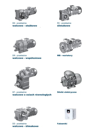
PRZEKŁADNIE WALCOWO-STOŻKOWE
SERIA DK
SPISTREŚCI
4
5
6
4
3
Nameplate
Versions of the DK series drives
Introduction
Construction scheme
Smarowanie i pozycje pracy
Lubrication and mounting positions
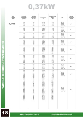
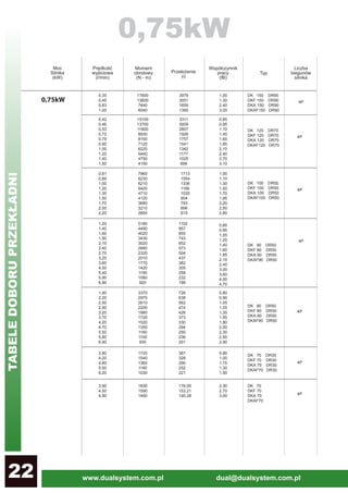
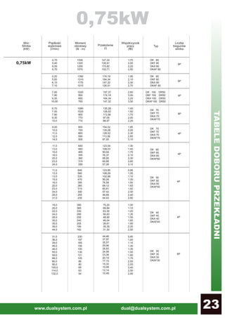
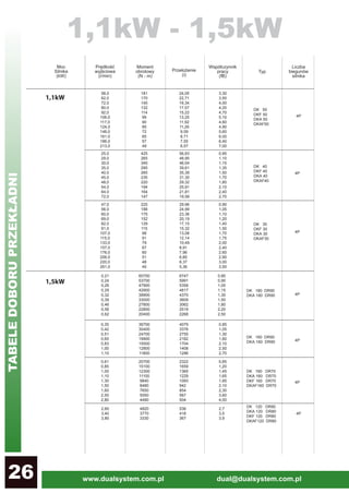
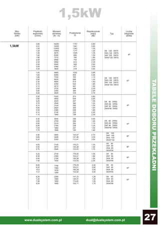
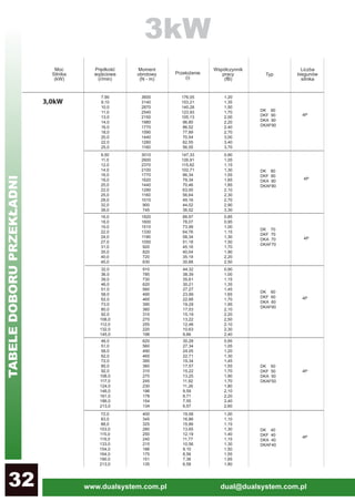
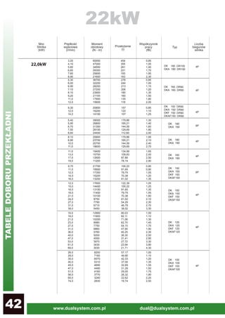
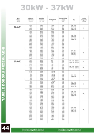
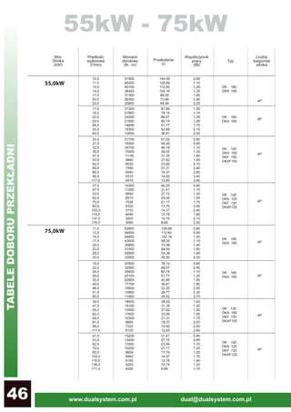
Dobór przekładni
Gearbox selection
Waga przekładni
Gearbox weight
8
8
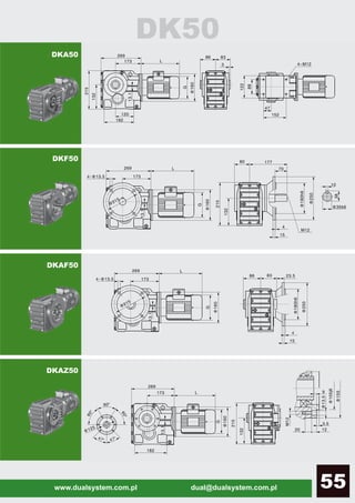
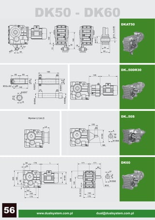
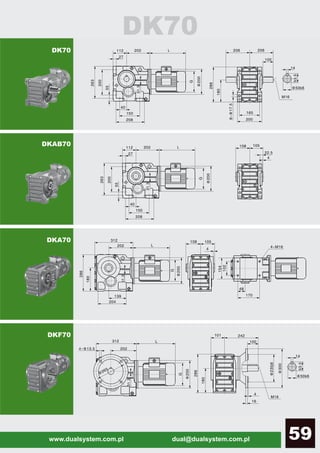
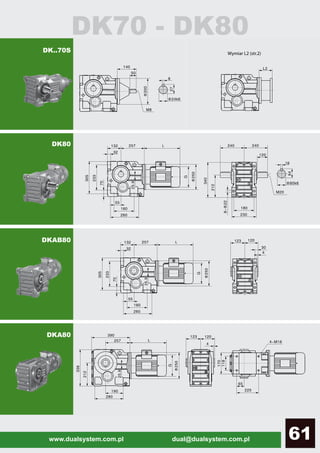
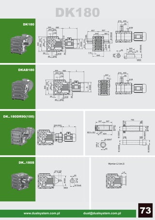
48 Wymiary
Dimensions
Kołnierz zdawczy IEC
IEC Output flange
4.
www.dualsystem.com.pl dual@dualsystem.com.pl2
1 Wstęp
Introduction
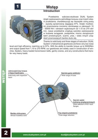
Przekładnie walcowo-stożkowe DUAL System
dzięki zastosowaniu jednolitego korpusu oraz trzech stop-
ni przełożenia, charakteryzują się niezwykle cichą pracą
i wysoką sprawnością sięgającą 97%. Dzięki możliwo-
ści przenoszenia momentu obrotowego w zakresach 10
- 50000 Nm i obrotach wyjściowych od 1,10 do 270 obr/
min, nasze przekładnie znajdują szerokie zastosowanie
w budowie wciągarek, podajników, mocno obciążonych
taśm produkcyjnych, suwnic, pras, i wielu innych urzą-
dzeń przenoszących bardzo duże siły.
Thanks to solid body and three stages of reduction, DUAL
System`s helical-bevel gearboxes archieve very low noise
level and high efficiency, reaching up to 97%. With the ability to transfer torque up to 50000Nm
and output speed from 1,10 to 270 RPM, our gearboxes are widely used in construction of win-
ches, feeders, heavy loaded transmission belts, gantry cranes, and any constructions that trans-
fer very heavy loads.
Szeroka gama wielkości
Jednoczęściowy korpus
z klapą inspekcyjną
Trzy stopnie przełożenia
Szeroki wybór
kołnierzy przyłączeniowych
Bardzo cicha praca
Solid body with inspection
hatch
Wide range of sizes
Wide selection of IEC input
flanges
Three stage reductionAlmost noiseless work
WSTĘP
5.
www.dualsystem.com.pl dual@dualsystem.com.pl 3
2Budowa przekładni
Construction scheme
1
Uszczelniacz
2
3 Łożysko
4
Koło zębate
5
Klin
10
Pierścień dystansowy
Zaślepka
Pierscień segera
Łożysko
14 Pierścień dystansowy
19
Pierścień dystansowy
20
Łożysko
Pierścień segera
Pierścien dystansowy
23 Wskaźnik poziomu oleju
Klin
Łożysko
Pierścień segera
Łożysko
21
22
28
29
30
31
Oil seal
Seger ring
Bearing
Gear wheel
Key
Spacer ring
Plug
Seger ring
Bearing
Spacer ring
Spacer ring
Bearing
Seger ring
Spacer ring
Oil indicator
Key
Bearing
Seger ring
Bearing
6
Wał wyjściowy
7
Klin
8
Łożysko
9
Pierścień segera
Wałek atakujący
Klin
Koło zębate
18
Tuleja wału
24
Śruba
Korek Oleju
Pokrywa
27
Koło zębate
Podkładka
Nakrętka
Koło zębate
25
26
33
34
32
Output shaft
Key
Bearing
Seger ring
Shaft
Key
Gear wheel
Shaft guide brush
Screw
Oil plug
Cover
Gear wheel
Gasket
Cap
Gear wheel
Pierścień segera
11
12
13
15
16
17
Wałek atakujący
35 Shaft
BUDOWAPRZEKŁADNI
6.
www.dualsystem.com.pl dual@dualsystem.com.pl4
2 Budowaprzekładni CD.
Construction scheme
Przekładnia walcowo-stożkowa DUAL Sys-
tem standardowo malowana jest na kolor RAL
7031. Składa się z jednoczęściowego korpusu
żeliwnego z klapą inspekcyjną (26). Pierwszym
stopniem redukcji jest wałek stożkowy (27)
przenoszący dzięki zębatce (32) moc z wałka
atakującego (35) na wałek pośredni (15) z któ-
rego moc jest przekazywana na wał zdawczy
(6) za pomocą walcowego koła zębatego (4).
The DUAL System`s helical-bevel gearbox
is painted by default to RAL 7031 colour. It`s
design includes a cast iron body with inspec-
tion hatch (26). The first stage of reduction is
bevel shaft (27), that transmits power by gear
(32) from input shaft (35) to intermediate shaft,
which drives output shaft (6) with helical gear
(4).
Tabliczka znamionowa prze-
kładni walcowo-stożkowej DK znajdu-
je się na górze korpusu przekładni. Moż-
na na niej znaleśc nastepujące informacje:
Nameplate of the DK helical-bevel ge-
arbox can be found on top of the body. It con-
sist information such as: .
TYP
PRZEŁOŻENIE
ROZMIAR KOŁNIERZA PRZYŁĄCZENIOWEGO IEC
TYPE
RATIO
SIZE OF THE IEC INPUT FLANGE
NUMER SERYJNY
SERIAL NUMBER
3 Tabliczka znamionowa
Nameplate
BUDOWAPRZEKŁADNI/TABLICZKAZNAMIONOWA
4 Waga przekładni
Weight
Typ DK30 DK40 DK50 DK60 DK70 DK80 DK90 DK100 DK120 DK150 DK160 DK180
waga 13 22 29 33 45 81 150 230 420 680 1050 1650
WAGA PRZEKŁADNI W KILOGRAMACH
GEARBOX WEIGHT IN KG
UWAGA: Waga w tabeli nie uwzględnia oleju. Jeżeli przekładnia zawiera wał wejściowy, należy doliczyć10% wagi.
7.
www.dualsystem.com.pl dual@dualsystem.com.pl 5
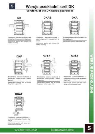
Przekładniawalcowo-stożkowa z
kołnierzem zdawczym B5 i wałem
drążonym
Przekładnia walcowo-stożkowa z
ramieniem reakcyjnym i wałem drą-
żonym
5 Wersje przekładni serii DK
Versions of the DK series gearboxes
Przekładnia walcowo-stożkowa z wa-
łem pełnym i mocowaniem łapowym.
Helical-bevel gearbox with output shaft
and foot mounting.
Przekładnia walcowo-stożkowa z
wałem drążonym i mocowaniem ła-
powym.
Helical-bevel gearbox with hollow shaft
and foot mounting.
Przekładnia walcowo-stożkowa z wa-
łem drążonym.
Helical-bevel gearbox with hollow shaft
Przekładnia walcowo-stożkowa z
kołnierzem zdawczym B5 i wałem
pełnym.
Helical-bevel gearbox with B5 output
flange and output shaft.
Przekładnia walcowo-stożkowa z
kołnierzem zdawczym B14 i wałem
drążonym.
Helical-bevel gearbox with B5 output
flange and hollow output shaft.
Helical-bevel gearbox with B5 output
flange and hollow output shaft.
Helical-bevel gearbox with torque arm
and hollow output shaft.
DK DKAB DKA
DKF DKAF DKAZ
DKAT
WERSJEPRZEKŁADNI
8.
www.dualsystem.com.pl dual@dualsystem.com.pl6
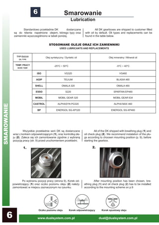
Standardowoprzekładnie DK dostarczane
są do klienta napełnione olejem, którego typy oraz
zamienniki wyszczególniono w tabeli poniżej.
All DK gearboxes are shipped to customer filled
with oil by default. Oli types and replacements can be
found in the table below.
6 Smarowanie
Lubrication
Wszystkie przekładnie serii DK są dostarczane
wraz z korkiem odpowietrzającym (1), oraz kontrolką ole-
ju (2). Zaleca się ich zamontowanie zgodnie z wybraną
pozycją pracy (str. 9) przed uruchomieniem przekładni.
All of the DK shipped with breathing plug (1) and
oil check plug (2). We recommend instalation of the plu-
gs according to choosen mounting position (p. 9), before
starting the gearbox.
STOSOWANE OLEJE ORAZ ICH ZAMIENNIKI
USED LUBRICANTS AND REPLACEMENTS
Po wybraniu pozycji pracy (strona 9), Korek od-
powietrzający (1) oraz oczko poziomu oleju (2) należy
zamontować w miejscu zaznaczonym na rysunku.
1. 2.
After mounting position has been chosen, bre-
athing plug (1) and oil check plug (2) has to be installed
according to the mounting scheme on p.9
Oczko poziomu oleju Korek odpowietrzający Korek spustowy oleju
TYP OLEJU
OIL TYPE
Olej syntetyczny / Syntetic oil Olej mineralny / Mineral oil
TEMP. PRACY
WORK TEMP.
-25*C ~ 50*C -5*C ~ 40*C
ISO VG320 VG460
AGIP TELIUM BLASIA 460
SHELL OMALA 320 OMALA 460
ESSO S220 SPARTAN EP460
MOBIL MOBIL GEAR 320 MOBIL GEAR 634
CASTROL ALPHASYN PG320 ALPHA MAX 460
BP ENERGOL SG-XP320 ENERGOL SG-XP460
SMAROWANIE
9.
www.dualsystem.com.pl dual@dualsystem.com.pl 7
ILOŚĆOLEJU POTRZEBNA DO PRACY W ODPOWIEDNIEJ POZYCJI ( W LITRACH)
Wielkość przekładni:
Gearbox size:
DK30 DK40 DK50 DK60 DK70 DK80 DK90 DK100 DK130 DK150 DK160 DK180
POZYCJA
PRACY
MOUNTING
POSITION
M1,
MF6
0,50L 1,00L 1,20L 1,50L 2,50L 3,50L 7,00L 10,0L 22,0L 30,0L 35,0L 65,0L
M2,
MF2
1,00L 1,50L 2,00L 2,50L 4,00L 8,00L 14,5L 22,0L 42,0L 65,0L 100L 175L
M3,
MF5
1,00L 2,00L 2,50L 3,00L 4,50L 10,0L 17,50L 25,0L 45,0L 70,0L 100L 175L
M4,
MF4
1,50L 2,50L 3,00L 3,50L 6,00L 12,0L 22,0L 35,0L 55,0L 93,0L 130L 200L
M5,
MF1
1,00L 1,50L 2,00L 2,50L 4,50L 8,50L 15,5L 25,0L 40,0L 65,0L 85,0L 135L
M6,
MF3
1,00L 1,50L 2,50L 3,00L 4,50L 8,50L 16,50L 25,0L 42,0L 65,0L 85,0L 135L
AMOUNT OF OIL REQUIED TO OPERATE IN SPECIFIC MOUNTING POSITION
DK47
DK47
POZYCJEPRACY
10.
www.dualsystem.com.pl dual@dualsystem.com.pl8
DLA LICZBYURUCHOMIEŃ NA GODZINĘ MNIEJSZEJ OD 10
Rodzaj obciążenia
Motoreduktora:
Type of encumbrance of gear-
motor:
stałe
constant
nieznaczne obciążenia
moderate shock
znaczne obciążenia
heavy shock
Czas pracy na dobę (w godzinach):
work hours per day:
<2 2~8 8~16
fB=0,8 fB=1 fB=1,25
fB=1 fB=1,25 fB=1,5
fB=1,25 fB=1,5 fB=1,75
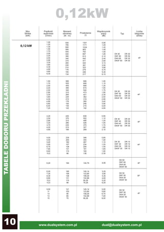
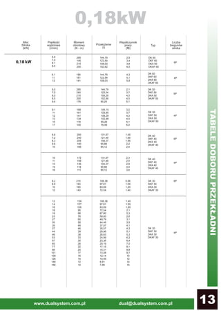
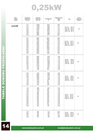
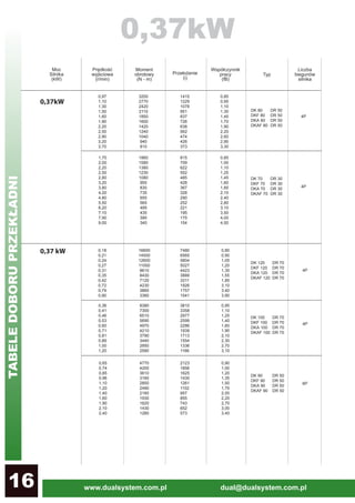
Dobór przekładni należy rozpocząć od określenia wy-
maganego współczynnika pracy (fB), określającego stosunek
momentu obrotowego przenoszonego przez przekładnię do mak-
symalnego obciążenia określonego przez producenta. Wyma-
gany Współczynnik fB należy określić wg poniższych tabel:
Gearbox selection should be started with determining
required service factor (fB), that specify proportion between torque
transfered by gearbox and maximum load of gearbox, specified by a
manufacturer. Requied fB factor can be defined with tables below:
Znając wymagany współczynnik pracy (fB) i moc na-
pędu (T2) wyrażoną w Nm, można przystapić do wyboru motore-
duktora z tabel znajdujących się na następnych stronach.
When requied service factor and Gearbox power (T2) are
known, the gearmotor can be selected from tables on the following
pages.
8 Dobór przekładni
Gearbox selection
LESS THAN 10 STARTS PER HOUR
DOBÓRPRZEKŁADNI
DLA LICZBY URUCHOMIEŃ NA GODZINĘ MNIEJSZEJ OD 10
Rodzaj obciążenia
Motoreduktora:
Type of encumbrance of gear-
motor:
stałe
constant
nieznaczne obciążenia
moderate shock
znaczne obciążenia
heavy shock
Czas pracy na dobę (w godzinach):
work hours per day:
<2 2~8 8~16
fB=1 fB=1,25 fB=1,75
fB=1,5 fB=1,75 fB=2
fB=1,75 fB=2 fB=2,25
LESS THAN 10 STARTS PER HOUR
7 Kołnierz zdawczy IEC
IEC output flange
63 71 80 90 100 112 132 160 180 200 225 250 280 315
DK30 61,5 61,5 80 80 98 - - - - - - - - -
DK40 56 56 74,5 74,5 90,5 - - - - - - - - -
DK50 56 56 74,5 74,5 90,5 90,5 - - - - - - - -
DK60 56 56 74,5 74,5 90,5 90,5 123 - - - - - - -
DK70 50 50 68,5 68,5 82,5 82,5 111 152,5 - - - - - -
DK80 - - 63,5 63,5 78,5 78,5 108 147,5 147,5 - - - - -
DK90 - - - 57,5 72,5 72,5 101 142,5 142,5 144,5 - - - -
DK100 - - - - 66,5 66,5 95 136,5 136,5 138,5 168,5 - - -
DK120 - - - - - - 80 121,5 121,5 123,5 153,5 153,5 153,5 -
DK150 - - - - - - - 113,5 113,5 115,5 145,5 145,5 145,5 175,5
DK160 - - - - - - - 113,5 113,5 115,5 145,5 145,5 145,5 175,5
DK180 - - - - - - - 113,5 113,5 115,5 145,5 145,5 145,5 175,5
WIELKOŚĆPRZEKŁADNI
WIELKOŚĆ SILNIKA / MOTOR SIZE
DŁUGOŚĆ KOŁNIERZA ZDAWCZEGO IEC (L2)
IEC OUTPUT FLANGE SIZE (L2)