The document describes the PC boot up sequence and disk organization.
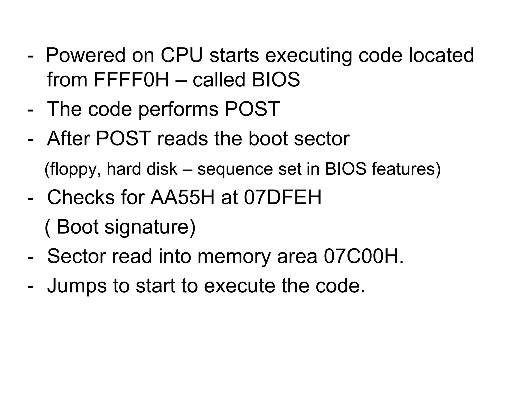
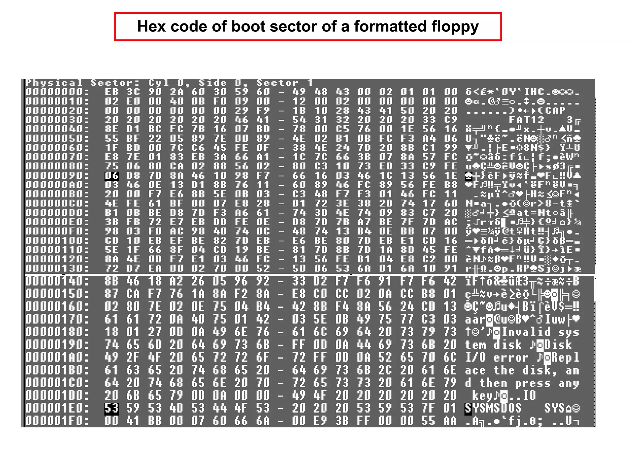
- The CPU executes BIOS code at FFFF0H during boot up. It performs POST and reads the boot sector from the hard disk or floppy disk.
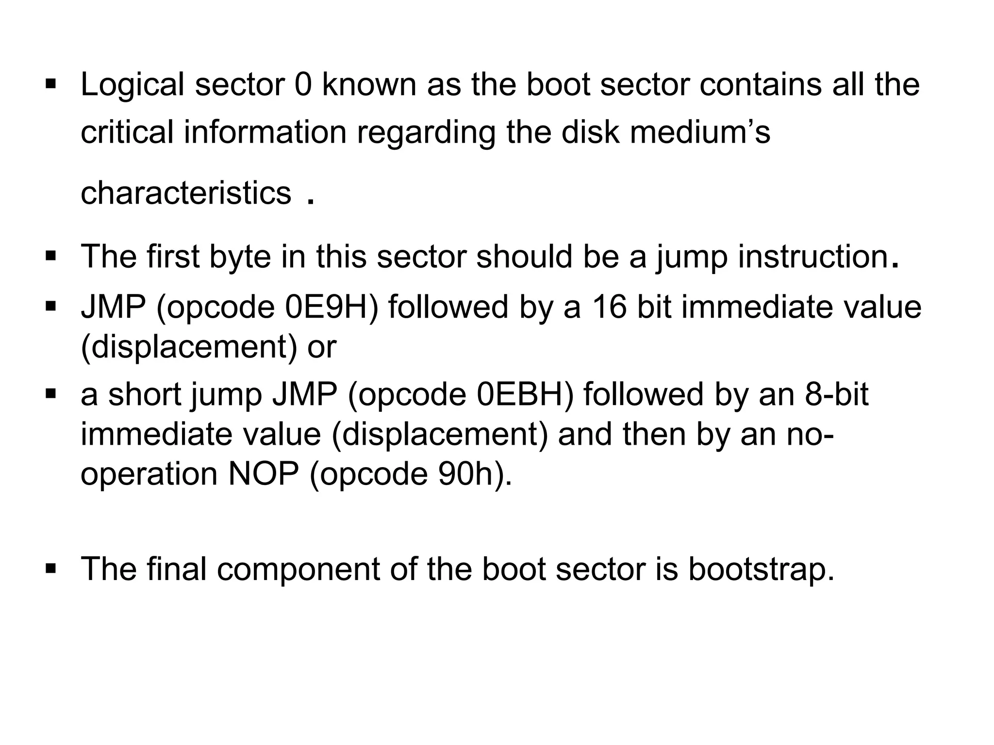
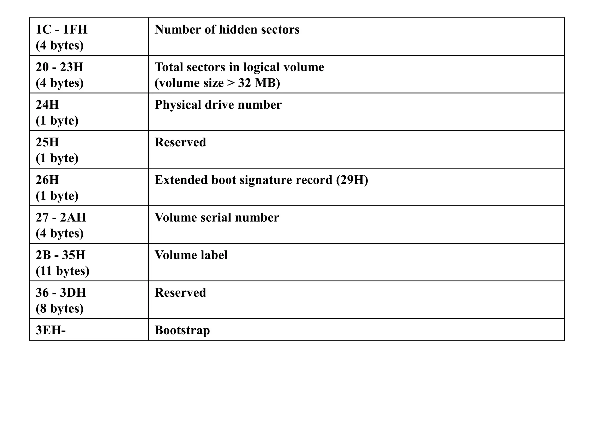
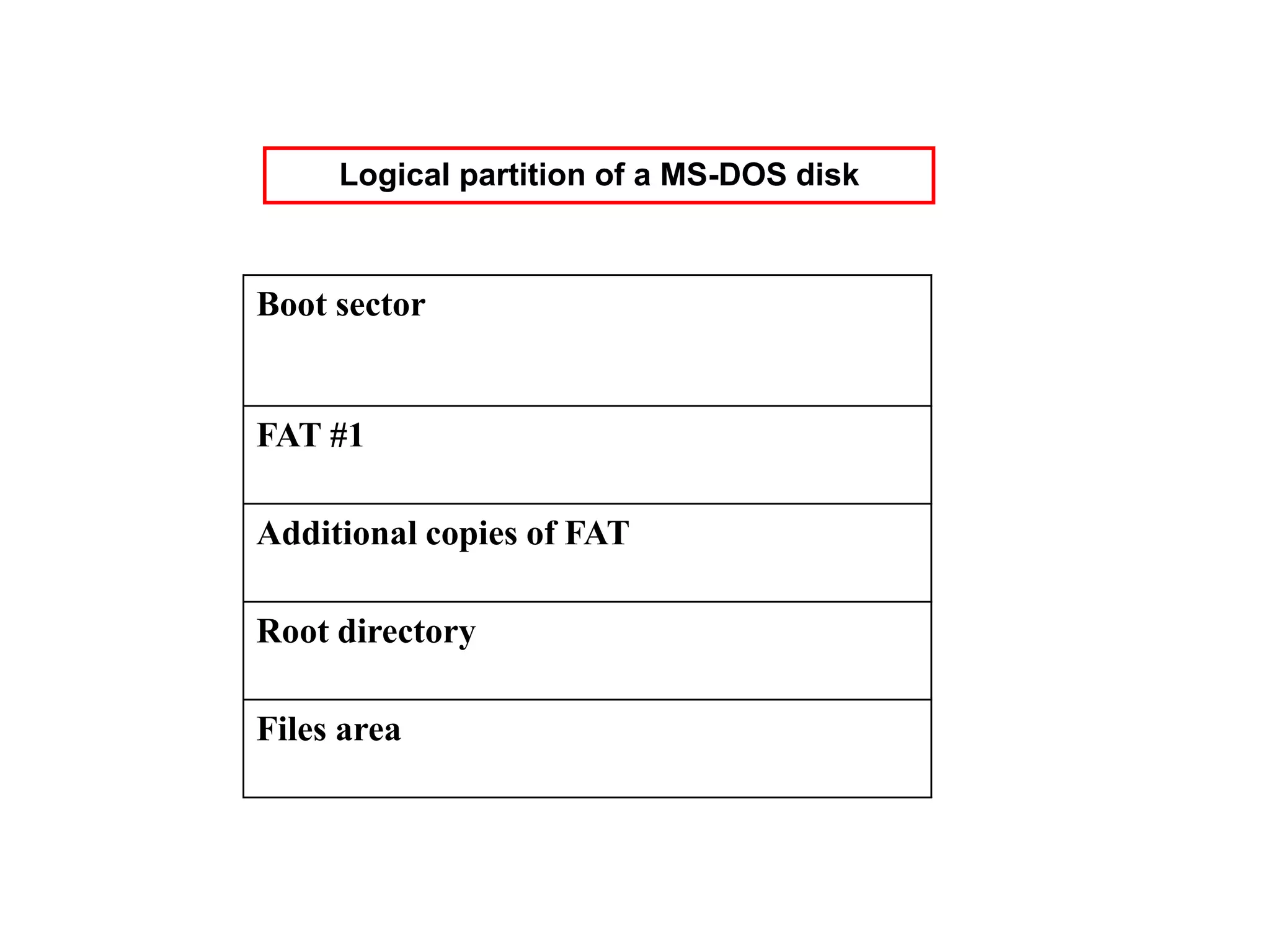
- The boot sector contains critical disk information like the disk structure and a jump instruction to load the operating system code.
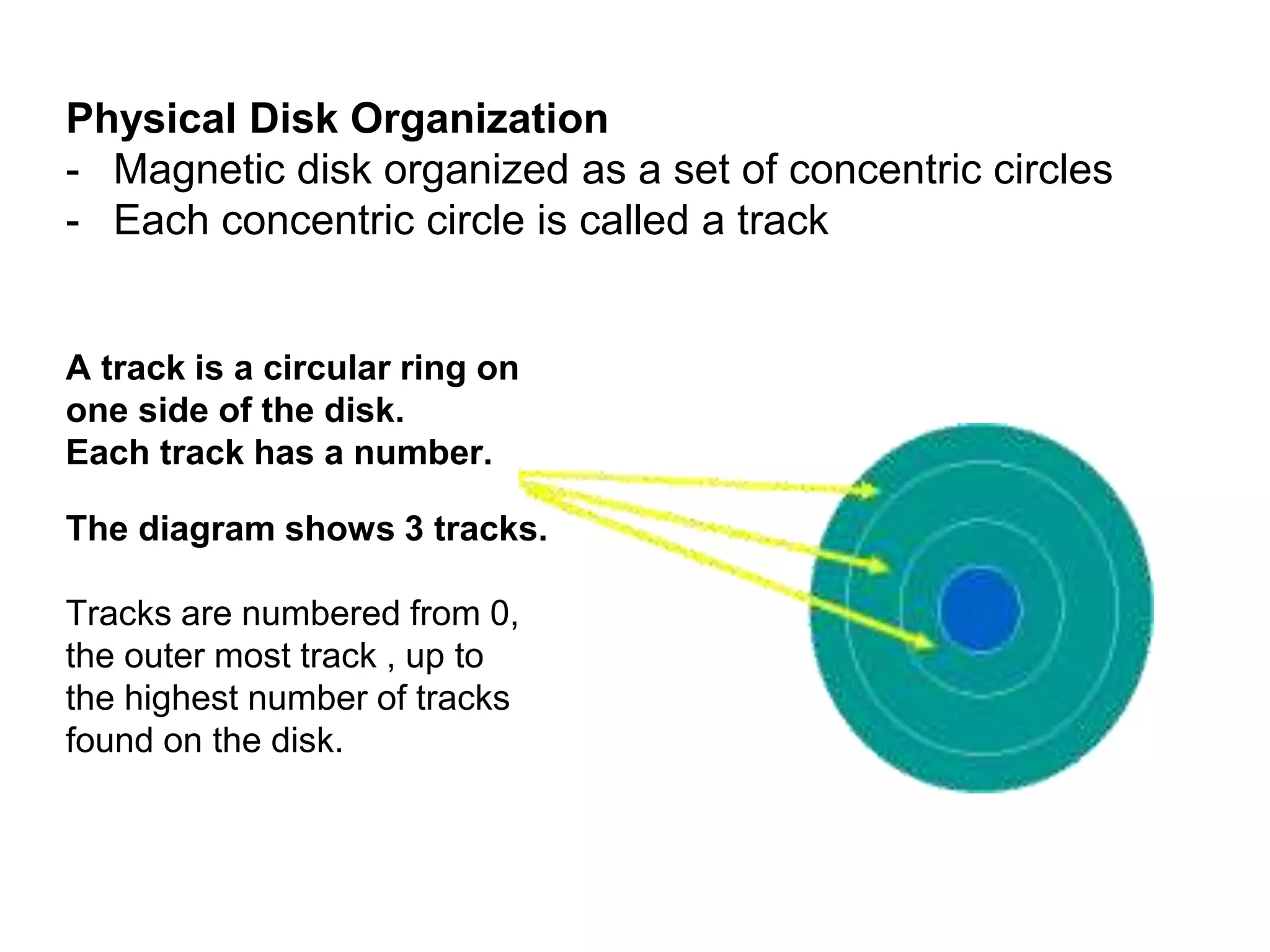
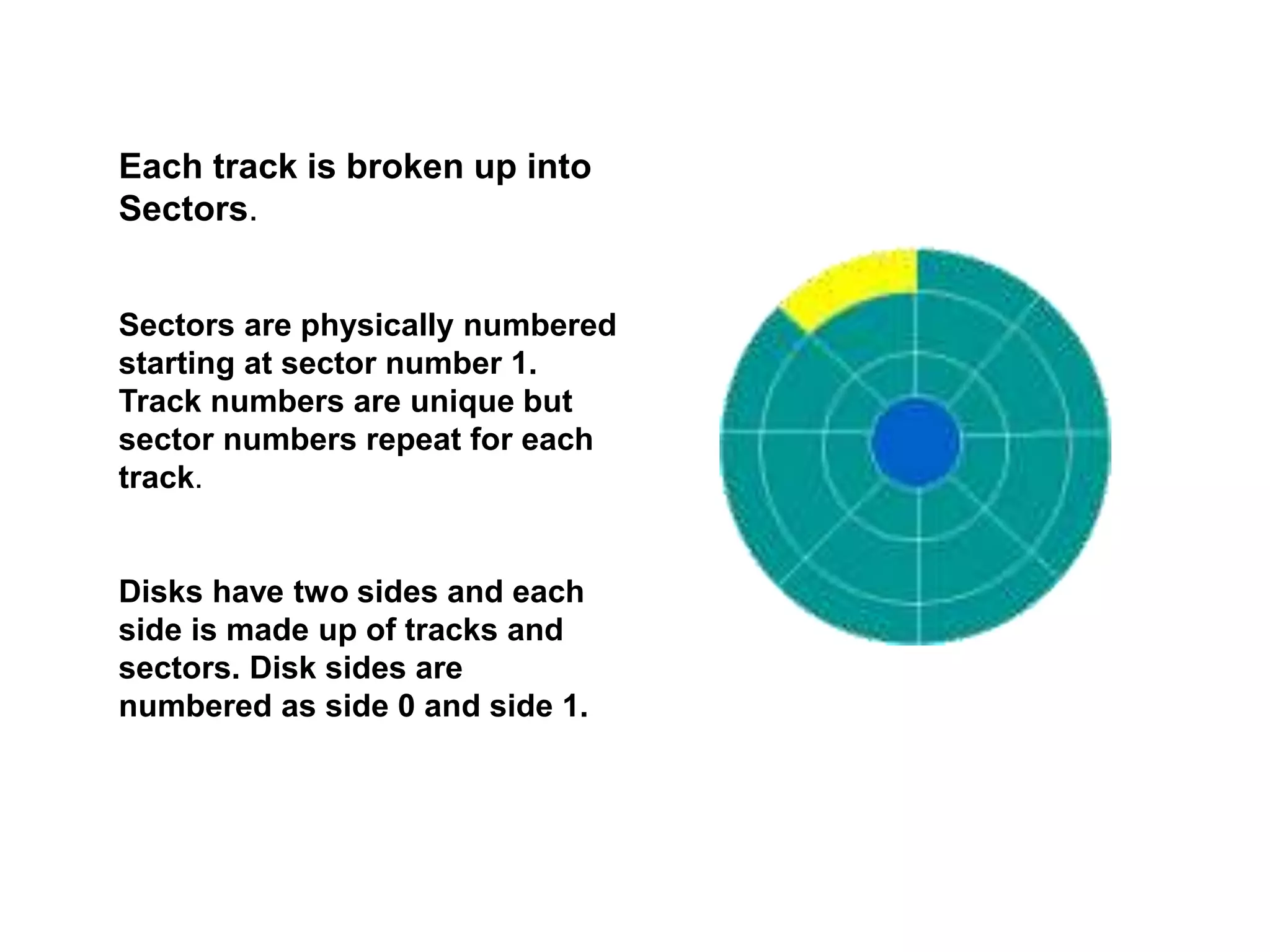
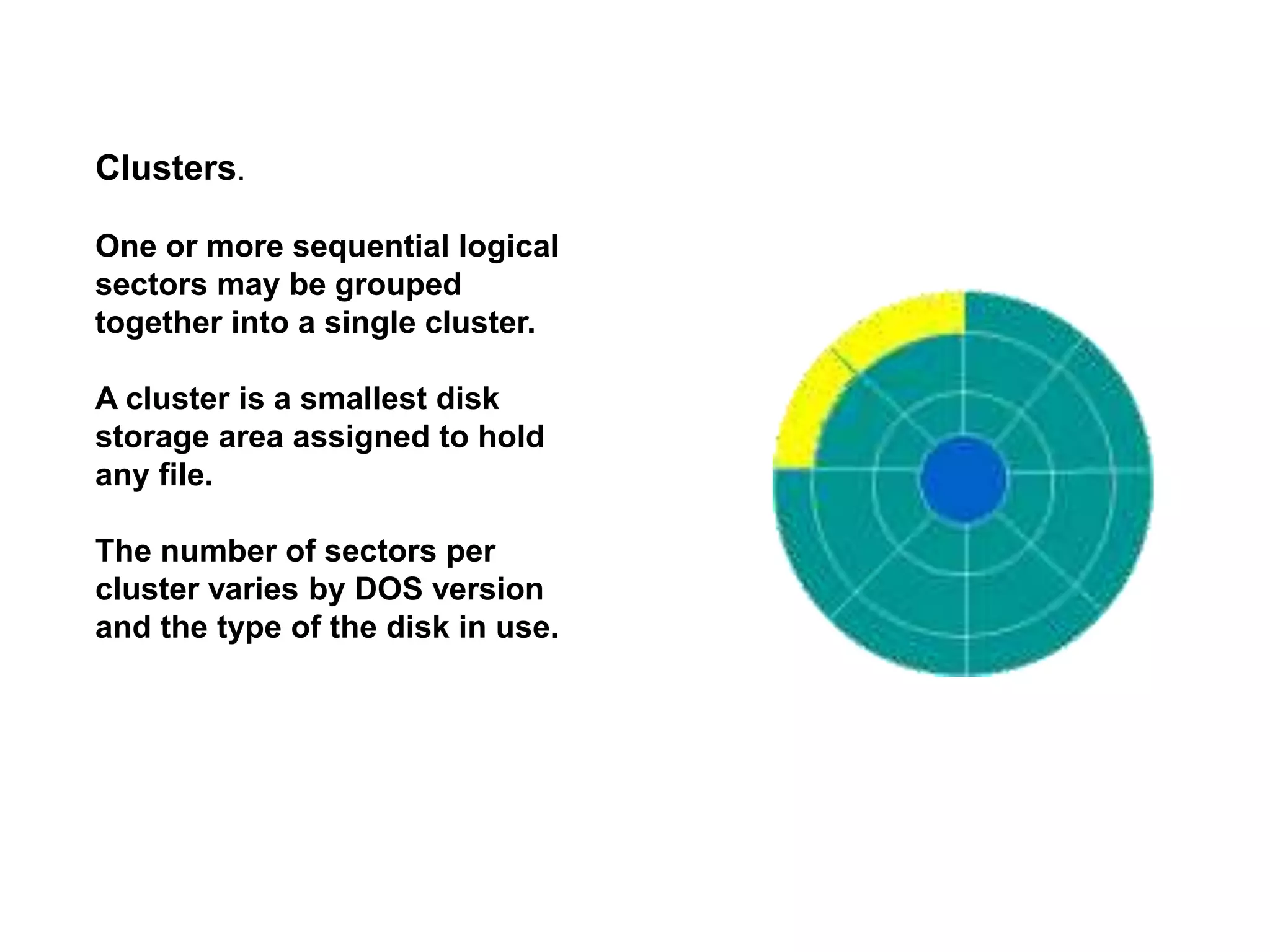
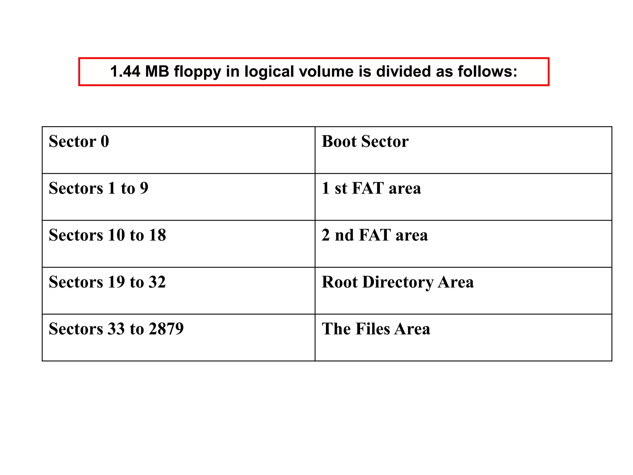
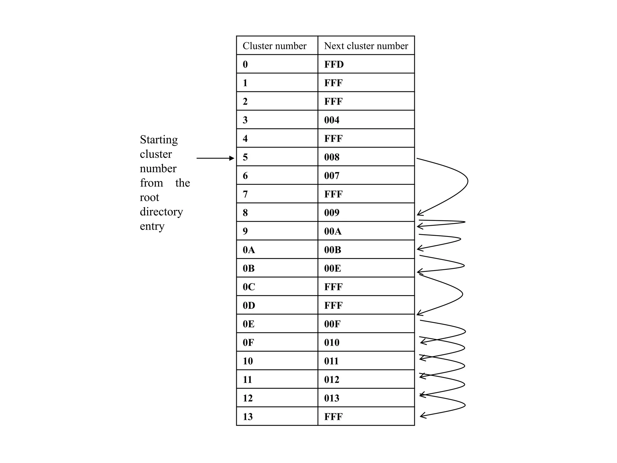
- A disk is organized into tracks, sectors, and clusters to logically store and access files. The boot sector layout defines this organization.