Download to read offline

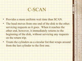
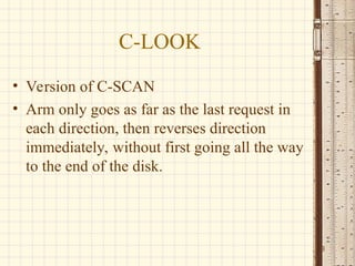
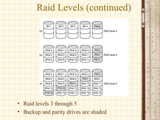
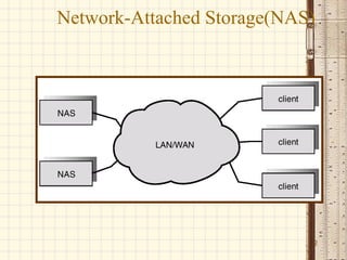
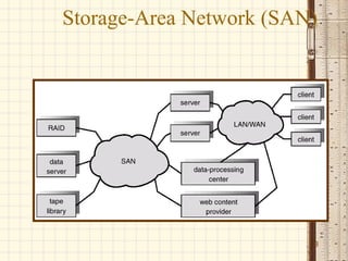

El documento aborda la programación de discos y la estructura del sistema de almacenamiento, explicando conceptos como bloques lógicos y el rendimiento del disco. Se discuten varios algoritmos de programación de E/S para discos, como FCFS, SSTF, SCAN, C-SCAN y C-LOOK, resaltando sus ventajas y desventajas. Además, se menciona RAID como un método para mejorar la fiabilidad del almacenamiento a través de la redundancia y se introducen conceptos avanzados como NAS y SAN.