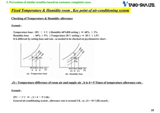
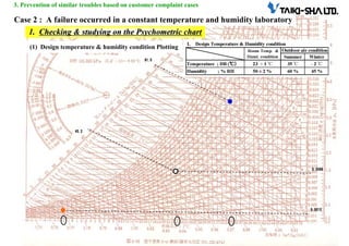
The document discusses the use and understanding of psychrometric charts in managing air-conditioning systems, particularly in preventing issues related to humidity and temperature control in various settings. It provides case studies highlighting problems like vapor carrying-over due to improper humidity settings and deficient humidification in office buildings. Solutions and key factors for effective air-conditioning management, including checking conditions on psychrometric charts, are emphasized to avoid recurrence of these issues.
![3
3
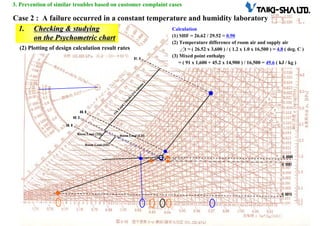
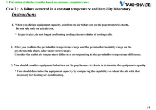
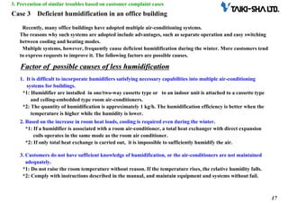
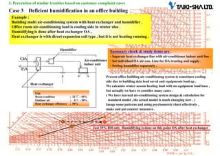
3. Prevention of similar troubles based on customer complaint cases
[Circumstances/conditions]
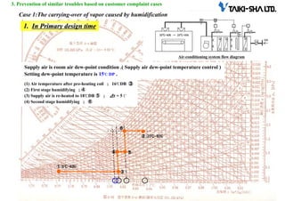
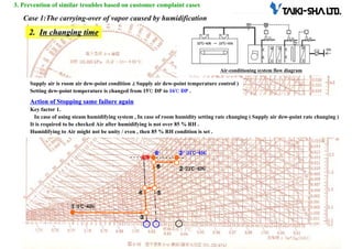
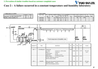
Case 1:The carrying-over of vapor caused by humidification
(Quality complaint information No. 62-013)
In a factory, the setting of the air-supply dew point temperature was changed from 60% ±10% to 65% ± 10%.
Humidified vapor was saturated and carried over. The carried-over vapor wetted the ceiling of the HEPA outlet and
dropped from the ceiling. HEPA is the acronym of High Efficiency Particulate Air.
In addition, defective products were produced due to the abnormal deterioration of the room pressure.
[Backgrounds]
The room, where the trouble occurred, was an explosion-protective area. It had an air-conditioning system
operated by a once-through type outdoor air-conditioner.
The setting of the relative humidity of the room was raised to reduce the generation of static electricity.
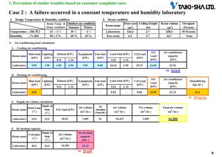
[Countermeasures to prevent recurrence]
Key factor 1
Key factor 1
Before changing the settings of the room humidity (the settings of the dew point temperature of the supply air) under the steam
humidification method, check the condition of the air after humidification on the psychrometric chart to see whether the
relative humidity is over 85%*.
*Consider that the air is not always humidified uniformly. Set the relative humidity at 85% or lower.
Key factor 2
Key factor 2
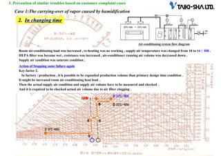
Heat generated from manufacturing equipment may have increased due to some reasons, for example, because of increased
products compared to the originally planned number. In advance, measure the current temperature and quantity of the supply
air, and know the room loads (caused by heat generation from equipment).
Check whether the air flow is reduced by filter clogging or not.
Key factor 3
Key factor 3
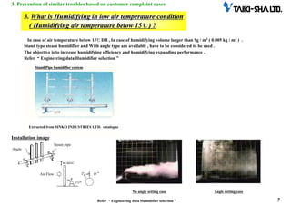
Note that under humidification at a lower temperature (the air is humidified at 15℃ or lower), the vapor absorption must be
longer than that under the humidification room temperature. If the air is humidified at a lower temperature, consider using
standpipe-equipped air-conditioners.
*See “Engineering data: Selection of humidifiers”.](https://image.slidesharecdn.com/06psychrometricno3-241216054907-5d0c4c85/85/Diagram-Psychometric-Chart-System-HVAC-pdf-3-320.jpg)