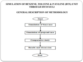
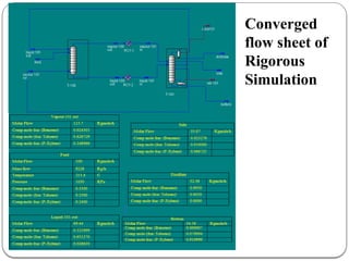
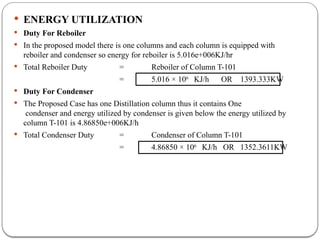
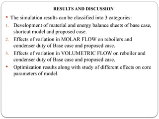
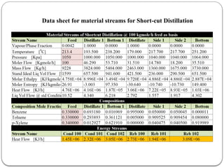
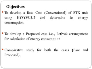
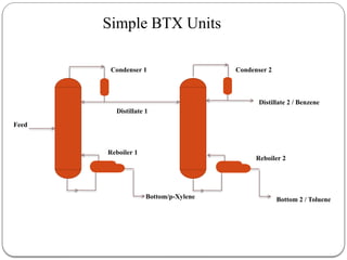
DESIGN STUDY OF ENERGY EFFICIENT DISTILLATION COLUMN THROUGH
HYSYS ® 3.2
BY
STUDENT’S NAME ROLL NO
MUHAMMAD ASIF (G.L) 08CH11
SHAFEEQUE AHMED (A.G.L) 08CH79
SHAHID ALI 08CH54
JAI KUMAR 08CH24
ABDUL GHAFFAR 08CH41
SHUAIB ABBASI 08CH27
IBRAR ALI KHOKHAR 08CH56
SUPERVISED BY
ENGR. IMRAN NAZIR UNAR
LECTURER
Chemical Engineering Department Mehran University Jamshoro
Contents
 Introduction
 Literature Review
 Simulation of base case
 Simulation of proposed case
 Results and discussion
 Conclusion
 References
INTRODUCTION
NEED OF ENERGY CONSERVATION
 High Energy Cost
 Energy Crises (especially in Pakistan)
 Factors affecting the SURVIVAL and SUSTAINABILITY of
chemical and process industries can be summarized as follows
 Threat of economic recession (especially in Asia),
 Political instability,
 Terrorism and war, which discourages new investments
 Globalization and international competition that drive industries towards
reducing manufacturing cost
 Global warming is now viewed seriously as this would affect the human life
in a few decades to come. Many of the developed countries are already
making efforts to find alternative solutions to reduce their contribution to
global warming.
METHODS OF ENERGY CONSERVATION IN DISTILLATION COLUMN
 Distillation in the chemical process industries accounts for 3% of
world’s energy consumption (Hernandez et al., 2006)
Energy Conservation
Methods
Upgrading Column Internals
Seasonal operating pressure
adjustment
Upgrading the Control System
Optimization in Operating
Conditions
Improved Heat Integration Vapor Recompression
Petlyuk Arrangement
Heat Pump
COLUMN CONFIGURATIONS IN PETYLUK
ARRANGEMENT
 02 Column Configurations
 Simple column configuration
 Complex column configuration
 Categories of Simple Column Configurations:
 Direct sequence
 Indirect sequence
 The distributed sequence
 Categories of Complex Column Configurations:
 Partially Thermally Coupled Distillation System (PTCDS)
 Fully Thermally Coupled Distillation System (FTCDS)
COLUMN CONFIGURATIONS IN PETYLUK
ARRANGEMENT
Indirect sequence
 Simple Column Configurations
Indirect sequence
Complex column configurations: partially thermally coupled distillation systems (PTCDS)
Complex column configurations: fully thermally coupled distillation systems (FTCDS)
 Complex Column Configurations
Objectives
 To develop a Base Case (Conventional) of BTX unit
using HYSYS®3.2 and determine its energy
consumption .
 To develop a Proposed case i.e., Petlyuk arrangement
for calculation of energy consumption.
 Comparative study for both the cases (Base and
Proposed).
Simple BTX Units
Feed
Bottom/p-Xylene Bottom 2 / Toluene
Distillate 2 / Benzene
Distillate 1
Condenser 1 Condenser 2
Reboiler 1
Reboiler 2
LITERATURE REVIEW
 Literature review forms an important part of research which helps to kick start the
research with valuable flow of information from the past research activities .
 It is very much necessary to understand the background of Petlyuk arrangement for
this purpose literature has been reviewed.
 The review reveals the existence of the technology, usage and acceptance of
Petlyuk arrangement (FTCDS) concept and recent developments in the technology.
Published Work On Petlyuk Arrangement
 Hernandez et al (2003) gave the concept about Design and energy performance of
alternative schemes of Petlyuk distillation system He used three types of thermally
coupled distillation systems namely the sequence with side rectifier, the sequence
with side stripper and the Petlyuk column .
 Ivor et al [2011] gave the concept of energy efficient distillation, according to them
distillation is responsible for a significant amount of energy consumption of the
world process industry. He said that The fully thermally coupled dividing wall
column has the attractive feature of both savings in energy consumption and
reduction of investment cost.
 Salvador et al [1999] gave the concept about design of energy efficient Petlyuk system;
in their paper the energy efficient design of FTCDS (Petlyuk system) was presented.
 Amminudin et al [2001] was done the work on design and optimization of Petlyuk
arrangement . He stated that the design of Petlyuk arrangement is more complex than
conventional arrangements because of the greater number of degrees of freedom.
 Salvador et al [1999] worked on controllability and analysis of thermally coupled
distillation system. He did the comparison of the controllability properties of TCDCS
(Petlyuk, sequence with side rectifier, and sequence with side stripper) using singular
value decomposition was developed.
 Amiya K.jana et al [2010] gave the concept about heat integrated distillation operation.
The heat integrated distillation has been researched for a number of decades.
 Rong et al [2006] gave new heat integration configuration for Petlyuk arrangement i.e.
The Petlyuk arrangement had been proved to require the minimum energy consumption
for multicomponent distillation that is an advantage for saving both energy and capital
costs.
 Michele et al [2007] worked on design of heat integrated distillation system for light
ends separation plant. The distillation systems employ the thermal coupling and the
heat integration principles to significantly reduce the heat requirements with respect
to the traditional simple column train.
 Premkumar et al [2009] worked on (DWC), which works on the basis of (FTCDS),
was chosen for this study due to its lower energy consumption compared to the
conventional column system.
 Malinen et al [2007] presented a method of rigorous minimum energy calculation
for non-ideal multicomponenet distillation. The method was based on column
simulation with a large number of equilibrium stages to mimic infinitely high
columns.
SIMULATION OF BENZENE, TOLUENE & P-XYLENE (BTX) UNIT
THROUGH HYSYS®3.2
GENERAL DESCRIPTION OF METHODOLOGY
PROBLEM DEFINITION
(Data has been taken from literature as basis)
 Feed Conditions:
 Benzene : 0.33 mole fraction
 Toluene : 0.33 mole fraction
 p-Xylene : 0.34 mole fraction
 Flow rate : 100 kgmol/h, Pressure: 10.5 atm, saturated liquid
Product Specifications:
 Benzene : 99.5% purity by molar basis
 Toluene : 91% purity by molar basis
 p- Xylene : 92% purity by molar basis
Other conditions:
 Column Pressure : 10 atm
 Condenser : Total Condenser
 Fluid Package : Peng-Robinson
Converged Flow Sheet of Base Case (conventional case)
 ENERGY UTILIZATION IN BASE CASE
 Duty For Reboiler
 In the base model there are two columns and each column is equipped with reboiler and
condenser so the base case contains two reboiler, energy for first reboiler is 5.421e+006
KJ/hr.
 Similarly Energy for Second Reboiler is 3.193e+006 KJ/h
 Total Reboiler Duty = Reboiler of Column T-100 + Reboiler of Column T-
101
 Total Reboiler Duty = 5.421×10⁶
+ 3.193×10⁶
KJ/h
= 8.614×10⁶
KJ/h OR 2392.77 KW
 Duty For Condenser
 The base case has two column thus it contains two condenser and energy utilized by
condenser is given below the energy utilized by column T-100 is 5.32312e+006KJ/h
 The energy which is utilized by second condenser is 3.15634e+006kJ/hr.
 Total condenser Duty = Condenser of Column T-100 + Condenser of Column T-
101
 Total condenser Duty = (5.32312×10⁶
+3.15643×10⁶
) KJ/h
= 8.485×10⁶
KJ/h OR 2356.944 KW
SIMULATION OF A PROPOSED CASE
(PETLYUK ARRANGEMENT)
 DESIGN METHOD AND PRINCIPLE
Variables to be known and estimated for FTCD
Flow chart - steps involved in the design of the column
SIMULATION PROCEDURE WITH HYSYS
1. Short cut distillation for finding initial estimates of variables required for rigorous
simulation
2. Rigorous simulation of FTCDS
3. Optimization of the system
SHORT CUT DISTILLATION FOR INITIAL ESTIMATES
Convergence of shortcut column shows equal composition of side1 and side 2
Rigorous Simulation
 FUG (fenske Underwood Gilliland) method for short cut distillation
calculations is based on several assumptions:
 The short cut method is based on assumptions that the relative volatility of
any two components is constant, the liquid/vapor molar flow rate is constant
on all stages, and a single feed (except for the reflux and boil up streams)
 One or more of these assumptions is often not valid and hence rigorous
simulation is necessary
 Once short cut estimates are completed, the estimates obtained can be used to
initiate the rigorous simulation of the FTCDS using HYSYS to get the
accurate results
Converged
flow sheet of
Rigorous
Simulation
 ENERGY UTILIZATION
 Duty For Reboiler
 In the proposed model there is one columns and each column is equipped with
reboiler and condenser so energy for reboiler is 5.016e+006KJ/hr
 Total Reboiler Duty = Reboiler of Column T-101
= 5.016 × 10⁶
KJ/h OR 1393.333KW
 Duty For Condenser
 The Proposed Case has one Distillation column thus it contains One
condenser and energy utilized by condenser is given below the energy utilized by
column T-101 is 4.86850e+006KJ/h
 Total Condenser Duty = Condenser of Column T-101
= 4.86850 × 10⁶
KJ/h OR 1352.3611KW
RESULTS AND DISCUSSION
 The simulation results can be classified into 3 categories:
1. Development of material and energy balance sheets of base case,
shortcut model and proposed case.
2. Effects of variation in MOLAR FLOW on reboilers and
condenser duty of Base case and proposed case.
3. Effects of variation in VOLUMETRIC FLOW on reboiler and
condenser duty of Base case and proposed case.
 Optimization results along with study of different effects on core
parameters of model.
MATERIALAND ENERGY BALANCE SHEETS FROM DEVELOPED
MODELS
Data Sheet For Material Streams For Base Case
Data sheet for material streams for Short-cut Distillation
Data Sheet For Material Streams For Proposed Case
 EFECT OF VARIATION IN MOLAR FLOW ON REBOILER AND
CONDENSER DUTY OF BASE CASE (CONVENTIONAL CASE)
Variation In Molar Flow On Base Case (Conventional Case)
 Effect on Reboiler Energy DueToVariation in Molar Flow (Base Case)
Effect Of Molar Flow On Reboiler Duty Of Base Case
1 25 50 75 100 125 150 175 200
0.000
1000.000
2000.000
3000.000
4000.000
5000.000
6000.000
Molar Flow VS Total Reboiler duty
Total Reboiler D...
Molar Flow (Kgmole/h)
Total
Reboiler
Duty
(KW)
Molar flow (kgmole/h)
Total Reboiler Duty
(kw)
1 23.950
25 598.990
50 1198.040
75 1796.930
100 2270.824
125 3011.990
150 3593.600
175 4192.450
200 4791.940
 Effect on Condenser Energy Due To Variation in Molar Flow (Base Case)
Effect Of Molar Flow On Condenser Duty Of Base Case
1 25 50 75 100 125 150 175 200
0.000
500.000
1000.000
1500.000
2000.000
2500.000
3000.000
3500.000
4000.000
4500.000
5000.000
Molar Flow VS Total Condenser duty
Total Condenser ...
Molar Flow (Kgmole/h)
Total
Condenser
Duty
(KW)
Molar flow(kgmole/h)
Total Condenser Duty
(kw)
1 23.604
25 590.070
50 1180.270
75 1770.540
100 2236.938
125 2950.820
150 3540.820
175 4130.820
200 4721.380
 EFFECT OF VARIATION IN MOLAR FLOW ON REBOILER AND CONDENSER
DUTY OF PROPOSED CASE
Variation In Molar Flow On Proposed Case
Effect On Reboiler Energy Due To Variation In Molar Flow (Proposed Case)
Effect of Molar Flow on Reboiler Duty of Proposed Case
1 25 50 75 100 125 150 175 200
0.000
500.000
1000.000
1500.000
2000.000
2500.000
3000.000
3500.000
4000.000
4500.000
5000.000
Molar Flow VS Reboiler-101 duty
Reb-101 Duty
Molar Flow (Kgmole/h)
Reboiler
Duty
(KW)
Molar Flow (Kgmole/h)
Reboiler-101
(kW)
1 27.106
25 932.220
50 1653.330
75 1778.330
100 1414.440
125 1950.270
150 2618.880
175 3563.880
200 4461.110
Effect On Condenser Energy Due To Variation In Molar Flow (Proposed Case)
Effect of Molar Flow on Condenser Duty of Proposed Case
1 25 50 75 100 125 150 175 200
0.000
500.000
1000.000
1500.000
2000.000
2500.000
3000.000
3500.000
4000.000
4500.000
5000.000
Molar Flow VS Condenser-101 duty
Cond-101 Duty
Molar Flow (Kgmole/h)
Condenser
Duty
(KW)
Molar flow(kgmole/h)
Condenser-101
(kW)
1 26.690
25 971.940
50 1632.770
75 1747.770
100 1373.611
125 1899.160
150 2557.500
175 3491.670
200 4380.550
EFFECT OF VARIATION IN VOLUMETRIC FLOW ON REBOILER AND
CONDENSER DUTY OF BASE CASE
Variation In Volumetric Flow On Base Case(Conventional Case)
Effect on Reboiler Energy Due To Variation in Volumetric Flow of Base Case
Effect of Volumetric Flow on Reboiler Duty of Base Case
500 1000 1500 2000 2500 3000 3500 4000
0.000
1000.000
2000.000
3000.000
4000.000
5000.000
6000.000
7000.000
Volumetric Flow VS Total Reboiler duty
Total Reboiler ...
Volumetric Flow (Barrels/day)
Total
Reboiler
Duty
(KW)
Volumetric Flow
(Barrels/Day)
Total Reboiler Duty
500 749.160
1000 1498.040
1500 2247.480
2000 2996.380
2500 3745.550
3000 4495.550
3500 5243.320
4000 5993.880
Effect on Condenser Energy Due To Variation in Volumetric Flow of Base
Case
Effect of Volumetric Flow on Condenser Duty of Base Case
500 1000 1500 2000 2500 3000 3500 4000
0.000
1000.000
2000.000
3000.000
4000.000
5000.000
6000.000
7000.000
Volumetric Flow VS Total Condenser duty
Total
Condenser ...
Volumetric Flow (Barrels/day)
Total
Condenser
Duty
(KW)
Volumetric Flow
(Barrels/Day)
Total Condenser
Duty(KW)
500 737.990
1000 1476.380
1500 2214.161
2000 2952.210
2500 3690.270
3000 4428.600
3500 5165.260
4000 5910.430
Effect of Volumetric flow on Reboiler and Condenser duty of Proposed Case
Variation in Volumetric Flow on Base Case(Conventional Case)
Effect on Reboiler Energy Due To Variation in Volumetric Flow of Proposed case
Effect of Volumetric Flow on Reboiler Duty of Proposed Case
500 1000 1500 2000 2500 3000 3500 4000
0.000
1000.000
2000.000
3000.000
4000.000
5000.000
6000.000
7000.000
8000.000
9000.000
Volumteric Flow VS Reboiler-101 duty
Reb-101 Duty
Volumeteric Flow (Barrels/day)
Reboiler
Duty
(KW)
Volumetric Flow
(Barrels/Day)
Reboiler-101
(kW)
500 463.388
1000 1445.000
1500 2345.830
2000 3611.110
2500 3930.550
3000 5083.330
3500 6358.330
4000 7788.880
Effect on condenser Energy Due To Variation in Volumetric Flow of Proposed Case
Effect of Volumetric Flow on Condenser Duty of Proposed Case
500 1000 1500 2000 2500 3000 3500 4000
0.000
1000.000
2000.000
3000.000
4000.000
5000.000
6000.000
7000.000
8000.000
Volumteric Flow VS Condenser-101 duty
Cond-101 Duty
Volumeteric Flow (Barrels/day)
Condenser
Duty
(KW)
Volumetric Flow
(Barrels/Day)
Condenser-101
(kW)
500 423.611
1000 1419.000
1500 2307.500
2000 3561.110
2500 3869.160
3000 5005.500
3500 6269.440
4000 7433.330
 OPTIMIZATION RESULTS ALONG WITH STUDY OF DIFFERENT EFFECTS ON
CORE PARAMETERS OF MODEL
 Optimize Feed Location Of Vapor101-in To Column T-101
Results
for
Optimization
COMPARATIVE STUDY
 Energy Used For Heating Purpose for Base Case (Conventional Case) and
Proposed Case
 Total reboiler duty is sum of REB-100 and REB-101 of Base Case.
 Total Reboiler Duty =8.614×10⁶
KJ/h or 2392.77 KW
 In the proposed case there is only one reboiler which is named as Reboiler-
101
 Hence total reboiler duty of proposed case is
 Total Reboiler Duty =5.016 × 10⁶
KJ/h OR 1393.333KW
 Energy Saved In Kw = 2392.77-1393.33 = 999.44KW
 Energy Saved In % = (999.44 / 2392.77) ×100 =41.78%
 Energy Used For Cooling Purpose for Base Case and Proposed Case
 total condenser duty is sum of COND-100 and COND-101 of Base Case.
 Total condenser Duty = 8.485×10⁶
KJ/h OR 2356.944 KW
 In the proposed case there is only one condenser which is named as
Condenser-101
 Total Condenser duty of proposed case is .
 Total condenser Duty = 4.86850 × 10⁶
KJ/h OR 1352.3611KW
 Energy Saved In KW = 2356.944 - 1352.3611 KW = 1004.5829 KW
 Energy Saved In % = (1004.5829/ 2356.944) ×100 = 42.62%
CONCLUSION
 Attempt has made to describe how to conserve energy in distillation operation. For
this purpose conventional system for Benzene, Toluene and Xylene (BTX)
separation unit was simulated in HYSYS®3.2 as Base Case in steady-state mode.
Then proposed case was also simulated based on Petlyuk arrangement (FTCDS).
 After the successful convergence of both cases, a comparison was made between the
energy consumption in both the system, calculated in HSYSY. Peng-Robbinson
fluid package was used in development of both the cases in HYSYS.
 It is concluded that 41.78% energy has saved for Reboiler duty where as 42.62%
energy has saved for Condenser duty without optimization.
 Hence more than 40% of energy can be saved by implementing (FTCDS) Petlyuk
arrangement.
References
1. Zsolt fonyo et al (2001); “Rigorous simulation of energy integrated and
thermally coupled distillation schemes for ternary mixture”; (2001); Department
of chemical engineering, Budapest university of Technology and Economics.
2. Premkumar et al (2009); “Retrofitting of conventional column systems to
divided wall columns”; (2009); Department of chemical and Bimolecular Engg:
national university of Singapore.
3. Malinen et al (2007); “A rigorous minimum energy calculation method for fully
thermally coupled distillation system”; (2007); Department of process and
environmental engineering, University of Oulu Finland.
4. Rong et al (2006); “New Heat integrated distillation configurations for petlyuk
arrangements”; (2006); Department of chemical technology, Lappeenranta
University of technology. Lappeenranta, Finland.
5. Michele et al (2007); “Design of heat integrated distillation systems for light
ends separation plant”; (2007); Department of engineering and chemical
materials ITALY.
6. Amminudin et al (2001); “Design and optimization of fully thermally coupled
distillation columns”; (2001); Department of process integration, UMIST.
7. Young et al (2004); “Structural design of fully thermally coupled distillation
columns using semi-rigorous model”; (2004); Department of chemical
engineering, Dong-A university.
8. Salvador et al (2009); “ Reactive dividing wall distillation columns: Simulation
and implementation in pilot plant”; (2009);
9. Ivor et al (2011); “Energy efficient distillation”. (NTNU) Department of Chemical
engineering, Norway.
10. Salvador et al (1999); “ Design of energy-efficient Petlyuk systems .” institute
Tecnolo´gico de Celaya, Departamento de Ingenierı´a Quı´mica, Celaya, Mexico
11. Amiya K.jana et al (2010); “Heat integrated distillation operation”; (2010);
Department of chemical engineering, Indian institute of technology.
12. Suying Zhao et al (2007), “Simulation of binary gas separation in hollow fiber
membrane–acetylene dehydration”, College of Chemistry and Chemical
Engineering, Fuzhou University, Fuzhou, Fujian, China.
13. Mc-cabe smith harriot.7th
edition, Unit operations of Chemical Engineering.
14. Massimiliano Errico et al (2009),” Energy saving and capital cost evaluation in
distillation column sequences with a divided wall column”. Università degli Studi
di Cagliari, Dipartimento di Ingegneria Chimica e Materiali, P.zza D’Armi sn.
15. Gelein de Koeijer et al (2003),” Entropy production and exergy loss in
experimental distillation columns”. Norwegian University of Science and
Technology, Department of Chemistry, Physical Chemistry, Trondheim, Norway.

Design of Efficient Distillation Column.pptx

  • 2.
    DESIGN STUDY OFENERGY EFFICIENT DISTILLATION COLUMN THROUGH HYSYS ® 3.2 BY STUDENT’S NAME ROLL NO MUHAMMAD ASIF (G.L) 08CH11 SHAFEEQUE AHMED (A.G.L) 08CH79 SHAHID ALI 08CH54 JAI KUMAR 08CH24 ABDUL GHAFFAR 08CH41 SHUAIB ABBASI 08CH27 IBRAR ALI KHOKHAR 08CH56 SUPERVISED BY ENGR. IMRAN NAZIR UNAR LECTURER Chemical Engineering Department Mehran University Jamshoro
  • 3.
    Contents  Introduction  LiteratureReview  Simulation of base case  Simulation of proposed case  Results and discussion  Conclusion  References
  • 4.
    INTRODUCTION NEED OF ENERGYCONSERVATION  High Energy Cost  Energy Crises (especially in Pakistan)  Factors affecting the SURVIVAL and SUSTAINABILITY of chemical and process industries can be summarized as follows  Threat of economic recession (especially in Asia),  Political instability,  Terrorism and war, which discourages new investments  Globalization and international competition that drive industries towards reducing manufacturing cost  Global warming is now viewed seriously as this would affect the human life in a few decades to come. Many of the developed countries are already making efforts to find alternative solutions to reduce their contribution to global warming.
  • 5.
    METHODS OF ENERGYCONSERVATION IN DISTILLATION COLUMN  Distillation in the chemical process industries accounts for 3% of world’s energy consumption (Hernandez et al., 2006) Energy Conservation Methods Upgrading Column Internals Seasonal operating pressure adjustment Upgrading the Control System Optimization in Operating Conditions Improved Heat Integration Vapor Recompression Petlyuk Arrangement Heat Pump
  • 6.
    COLUMN CONFIGURATIONS INPETYLUK ARRANGEMENT  02 Column Configurations  Simple column configuration  Complex column configuration  Categories of Simple Column Configurations:  Direct sequence  Indirect sequence  The distributed sequence  Categories of Complex Column Configurations:  Partially Thermally Coupled Distillation System (PTCDS)  Fully Thermally Coupled Distillation System (FTCDS)
  • 7.
    COLUMN CONFIGURATIONS INPETYLUK ARRANGEMENT Indirect sequence  Simple Column Configurations Indirect sequence
  • 8.
    Complex column configurations:partially thermally coupled distillation systems (PTCDS) Complex column configurations: fully thermally coupled distillation systems (FTCDS)  Complex Column Configurations
  • 9.
    Objectives  To developa Base Case (Conventional) of BTX unit using HYSYS®3.2 and determine its energy consumption .  To develop a Proposed case i.e., Petlyuk arrangement for calculation of energy consumption.  Comparative study for both the cases (Base and Proposed).
  • 10.
    Simple BTX Units Feed Bottom/p-XyleneBottom 2 / Toluene Distillate 2 / Benzene Distillate 1 Condenser 1 Condenser 2 Reboiler 1 Reboiler 2
  • 11.
    LITERATURE REVIEW  Literaturereview forms an important part of research which helps to kick start the research with valuable flow of information from the past research activities .  It is very much necessary to understand the background of Petlyuk arrangement for this purpose literature has been reviewed.  The review reveals the existence of the technology, usage and acceptance of Petlyuk arrangement (FTCDS) concept and recent developments in the technology. Published Work On Petlyuk Arrangement  Hernandez et al (2003) gave the concept about Design and energy performance of alternative schemes of Petlyuk distillation system He used three types of thermally coupled distillation systems namely the sequence with side rectifier, the sequence with side stripper and the Petlyuk column .  Ivor et al [2011] gave the concept of energy efficient distillation, according to them distillation is responsible for a significant amount of energy consumption of the world process industry. He said that The fully thermally coupled dividing wall column has the attractive feature of both savings in energy consumption and reduction of investment cost.
  • 12.
     Salvador etal [1999] gave the concept about design of energy efficient Petlyuk system; in their paper the energy efficient design of FTCDS (Petlyuk system) was presented.  Amminudin et al [2001] was done the work on design and optimization of Petlyuk arrangement . He stated that the design of Petlyuk arrangement is more complex than conventional arrangements because of the greater number of degrees of freedom.  Salvador et al [1999] worked on controllability and analysis of thermally coupled distillation system. He did the comparison of the controllability properties of TCDCS (Petlyuk, sequence with side rectifier, and sequence with side stripper) using singular value decomposition was developed.  Amiya K.jana et al [2010] gave the concept about heat integrated distillation operation. The heat integrated distillation has been researched for a number of decades.  Rong et al [2006] gave new heat integration configuration for Petlyuk arrangement i.e. The Petlyuk arrangement had been proved to require the minimum energy consumption for multicomponent distillation that is an advantage for saving both energy and capital costs.
  • 13.
     Michele etal [2007] worked on design of heat integrated distillation system for light ends separation plant. The distillation systems employ the thermal coupling and the heat integration principles to significantly reduce the heat requirements with respect to the traditional simple column train.  Premkumar et al [2009] worked on (DWC), which works on the basis of (FTCDS), was chosen for this study due to its lower energy consumption compared to the conventional column system.  Malinen et al [2007] presented a method of rigorous minimum energy calculation for non-ideal multicomponenet distillation. The method was based on column simulation with a large number of equilibrium stages to mimic infinitely high columns.
  • 14.
    SIMULATION OF BENZENE,TOLUENE & P-XYLENE (BTX) UNIT THROUGH HYSYS®3.2 GENERAL DESCRIPTION OF METHODOLOGY
  • 15.
    PROBLEM DEFINITION (Data hasbeen taken from literature as basis)  Feed Conditions:  Benzene : 0.33 mole fraction  Toluene : 0.33 mole fraction  p-Xylene : 0.34 mole fraction  Flow rate : 100 kgmol/h, Pressure: 10.5 atm, saturated liquid Product Specifications:  Benzene : 99.5% purity by molar basis  Toluene : 91% purity by molar basis  p- Xylene : 92% purity by molar basis Other conditions:  Column Pressure : 10 atm  Condenser : Total Condenser  Fluid Package : Peng-Robinson
  • 16.
    Converged Flow Sheetof Base Case (conventional case)
  • 17.
     ENERGY UTILIZATIONIN BASE CASE  Duty For Reboiler  In the base model there are two columns and each column is equipped with reboiler and condenser so the base case contains two reboiler, energy for first reboiler is 5.421e+006 KJ/hr.  Similarly Energy for Second Reboiler is 3.193e+006 KJ/h  Total Reboiler Duty = Reboiler of Column T-100 + Reboiler of Column T- 101  Total Reboiler Duty = 5.421×10⁶ + 3.193×10⁶ KJ/h = 8.614×10⁶ KJ/h OR 2392.77 KW  Duty For Condenser  The base case has two column thus it contains two condenser and energy utilized by condenser is given below the energy utilized by column T-100 is 5.32312e+006KJ/h  The energy which is utilized by second condenser is 3.15634e+006kJ/hr.  Total condenser Duty = Condenser of Column T-100 + Condenser of Column T- 101  Total condenser Duty = (5.32312×10⁶ +3.15643×10⁶ ) KJ/h = 8.485×10⁶ KJ/h OR 2356.944 KW
  • 18.
    SIMULATION OF APROPOSED CASE (PETLYUK ARRANGEMENT)  DESIGN METHOD AND PRINCIPLE Variables to be known and estimated for FTCD
  • 19.
    Flow chart -steps involved in the design of the column
  • 20.
    SIMULATION PROCEDURE WITHHYSYS 1. Short cut distillation for finding initial estimates of variables required for rigorous simulation 2. Rigorous simulation of FTCDS 3. Optimization of the system SHORT CUT DISTILLATION FOR INITIAL ESTIMATES Convergence of shortcut column shows equal composition of side1 and side 2
  • 21.
    Rigorous Simulation  FUG(fenske Underwood Gilliland) method for short cut distillation calculations is based on several assumptions:  The short cut method is based on assumptions that the relative volatility of any two components is constant, the liquid/vapor molar flow rate is constant on all stages, and a single feed (except for the reflux and boil up streams)  One or more of these assumptions is often not valid and hence rigorous simulation is necessary  Once short cut estimates are completed, the estimates obtained can be used to initiate the rigorous simulation of the FTCDS using HYSYS to get the accurate results
  • 22.
  • 23.
     ENERGY UTILIZATION Duty For Reboiler  In the proposed model there is one columns and each column is equipped with reboiler and condenser so energy for reboiler is 5.016e+006KJ/hr  Total Reboiler Duty = Reboiler of Column T-101 = 5.016 × 10⁶ KJ/h OR 1393.333KW  Duty For Condenser  The Proposed Case has one Distillation column thus it contains One condenser and energy utilized by condenser is given below the energy utilized by column T-101 is 4.86850e+006KJ/h  Total Condenser Duty = Condenser of Column T-101 = 4.86850 × 10⁶ KJ/h OR 1352.3611KW
  • 24.
    RESULTS AND DISCUSSION The simulation results can be classified into 3 categories: 1. Development of material and energy balance sheets of base case, shortcut model and proposed case. 2. Effects of variation in MOLAR FLOW on reboilers and condenser duty of Base case and proposed case. 3. Effects of variation in VOLUMETRIC FLOW on reboiler and condenser duty of Base case and proposed case.  Optimization results along with study of different effects on core parameters of model.
  • 25.
    MATERIALAND ENERGY BALANCESHEETS FROM DEVELOPED MODELS Data Sheet For Material Streams For Base Case
  • 26.
    Data sheet formaterial streams for Short-cut Distillation
  • 27.
    Data sheet formaterial streams for Short-cut Distillation
  • 28.
    Data Sheet ForMaterial Streams For Proposed Case
  • 29.
     EFECT OFVARIATION IN MOLAR FLOW ON REBOILER AND CONDENSER DUTY OF BASE CASE (CONVENTIONAL CASE) Variation In Molar Flow On Base Case (Conventional Case)
  • 30.
     Effect onReboiler Energy DueToVariation in Molar Flow (Base Case) Effect Of Molar Flow On Reboiler Duty Of Base Case 1 25 50 75 100 125 150 175 200 0.000 1000.000 2000.000 3000.000 4000.000 5000.000 6000.000 Molar Flow VS Total Reboiler duty Total Reboiler D... Molar Flow (Kgmole/h) Total Reboiler Duty (KW) Molar flow (kgmole/h) Total Reboiler Duty (kw) 1 23.950 25 598.990 50 1198.040 75 1796.930 100 2270.824 125 3011.990 150 3593.600 175 4192.450 200 4791.940
  • 31.
     Effect onCondenser Energy Due To Variation in Molar Flow (Base Case) Effect Of Molar Flow On Condenser Duty Of Base Case 1 25 50 75 100 125 150 175 200 0.000 500.000 1000.000 1500.000 2000.000 2500.000 3000.000 3500.000 4000.000 4500.000 5000.000 Molar Flow VS Total Condenser duty Total Condenser ... Molar Flow (Kgmole/h) Total Condenser Duty (KW) Molar flow(kgmole/h) Total Condenser Duty (kw) 1 23.604 25 590.070 50 1180.270 75 1770.540 100 2236.938 125 2950.820 150 3540.820 175 4130.820 200 4721.380
  • 32.
     EFFECT OFVARIATION IN MOLAR FLOW ON REBOILER AND CONDENSER DUTY OF PROPOSED CASE Variation In Molar Flow On Proposed Case
  • 33.
    Effect On ReboilerEnergy Due To Variation In Molar Flow (Proposed Case) Effect of Molar Flow on Reboiler Duty of Proposed Case 1 25 50 75 100 125 150 175 200 0.000 500.000 1000.000 1500.000 2000.000 2500.000 3000.000 3500.000 4000.000 4500.000 5000.000 Molar Flow VS Reboiler-101 duty Reb-101 Duty Molar Flow (Kgmole/h) Reboiler Duty (KW) Molar Flow (Kgmole/h) Reboiler-101 (kW) 1 27.106 25 932.220 50 1653.330 75 1778.330 100 1414.440 125 1950.270 150 2618.880 175 3563.880 200 4461.110
  • 34.
    Effect On CondenserEnergy Due To Variation In Molar Flow (Proposed Case) Effect of Molar Flow on Condenser Duty of Proposed Case 1 25 50 75 100 125 150 175 200 0.000 500.000 1000.000 1500.000 2000.000 2500.000 3000.000 3500.000 4000.000 4500.000 5000.000 Molar Flow VS Condenser-101 duty Cond-101 Duty Molar Flow (Kgmole/h) Condenser Duty (KW) Molar flow(kgmole/h) Condenser-101 (kW) 1 26.690 25 971.940 50 1632.770 75 1747.770 100 1373.611 125 1899.160 150 2557.500 175 3491.670 200 4380.550
  • 35.
    EFFECT OF VARIATIONIN VOLUMETRIC FLOW ON REBOILER AND CONDENSER DUTY OF BASE CASE Variation In Volumetric Flow On Base Case(Conventional Case)
  • 36.
    Effect on ReboilerEnergy Due To Variation in Volumetric Flow of Base Case Effect of Volumetric Flow on Reboiler Duty of Base Case 500 1000 1500 2000 2500 3000 3500 4000 0.000 1000.000 2000.000 3000.000 4000.000 5000.000 6000.000 7000.000 Volumetric Flow VS Total Reboiler duty Total Reboiler ... Volumetric Flow (Barrels/day) Total Reboiler Duty (KW) Volumetric Flow (Barrels/Day) Total Reboiler Duty 500 749.160 1000 1498.040 1500 2247.480 2000 2996.380 2500 3745.550 3000 4495.550 3500 5243.320 4000 5993.880
  • 37.
    Effect on CondenserEnergy Due To Variation in Volumetric Flow of Base Case Effect of Volumetric Flow on Condenser Duty of Base Case 500 1000 1500 2000 2500 3000 3500 4000 0.000 1000.000 2000.000 3000.000 4000.000 5000.000 6000.000 7000.000 Volumetric Flow VS Total Condenser duty Total Condenser ... Volumetric Flow (Barrels/day) Total Condenser Duty (KW) Volumetric Flow (Barrels/Day) Total Condenser Duty(KW) 500 737.990 1000 1476.380 1500 2214.161 2000 2952.210 2500 3690.270 3000 4428.600 3500 5165.260 4000 5910.430
  • 38.
    Effect of Volumetricflow on Reboiler and Condenser duty of Proposed Case Variation in Volumetric Flow on Base Case(Conventional Case)
  • 39.
    Effect on ReboilerEnergy Due To Variation in Volumetric Flow of Proposed case Effect of Volumetric Flow on Reboiler Duty of Proposed Case 500 1000 1500 2000 2500 3000 3500 4000 0.000 1000.000 2000.000 3000.000 4000.000 5000.000 6000.000 7000.000 8000.000 9000.000 Volumteric Flow VS Reboiler-101 duty Reb-101 Duty Volumeteric Flow (Barrels/day) Reboiler Duty (KW) Volumetric Flow (Barrels/Day) Reboiler-101 (kW) 500 463.388 1000 1445.000 1500 2345.830 2000 3611.110 2500 3930.550 3000 5083.330 3500 6358.330 4000 7788.880
  • 40.
    Effect on condenserEnergy Due To Variation in Volumetric Flow of Proposed Case Effect of Volumetric Flow on Condenser Duty of Proposed Case 500 1000 1500 2000 2500 3000 3500 4000 0.000 1000.000 2000.000 3000.000 4000.000 5000.000 6000.000 7000.000 8000.000 Volumteric Flow VS Condenser-101 duty Cond-101 Duty Volumeteric Flow (Barrels/day) Condenser Duty (KW) Volumetric Flow (Barrels/Day) Condenser-101 (kW) 500 423.611 1000 1419.000 1500 2307.500 2000 3561.110 2500 3869.160 3000 5005.500 3500 6269.440 4000 7433.330
  • 41.
     OPTIMIZATION RESULTSALONG WITH STUDY OF DIFFERENT EFFECTS ON CORE PARAMETERS OF MODEL  Optimize Feed Location Of Vapor101-in To Column T-101 Results for Optimization
  • 42.
    COMPARATIVE STUDY  EnergyUsed For Heating Purpose for Base Case (Conventional Case) and Proposed Case  Total reboiler duty is sum of REB-100 and REB-101 of Base Case.  Total Reboiler Duty =8.614×10⁶ KJ/h or 2392.77 KW  In the proposed case there is only one reboiler which is named as Reboiler- 101  Hence total reboiler duty of proposed case is  Total Reboiler Duty =5.016 × 10⁶ KJ/h OR 1393.333KW  Energy Saved In Kw = 2392.77-1393.33 = 999.44KW  Energy Saved In % = (999.44 / 2392.77) ×100 =41.78%
  • 43.
     Energy UsedFor Cooling Purpose for Base Case and Proposed Case  total condenser duty is sum of COND-100 and COND-101 of Base Case.  Total condenser Duty = 8.485×10⁶ KJ/h OR 2356.944 KW  In the proposed case there is only one condenser which is named as Condenser-101  Total Condenser duty of proposed case is .  Total condenser Duty = 4.86850 × 10⁶ KJ/h OR 1352.3611KW  Energy Saved In KW = 2356.944 - 1352.3611 KW = 1004.5829 KW  Energy Saved In % = (1004.5829/ 2356.944) ×100 = 42.62%
  • 44.
    CONCLUSION  Attempt hasmade to describe how to conserve energy in distillation operation. For this purpose conventional system for Benzene, Toluene and Xylene (BTX) separation unit was simulated in HYSYS®3.2 as Base Case in steady-state mode. Then proposed case was also simulated based on Petlyuk arrangement (FTCDS).  After the successful convergence of both cases, a comparison was made between the energy consumption in both the system, calculated in HSYSY. Peng-Robbinson fluid package was used in development of both the cases in HYSYS.  It is concluded that 41.78% energy has saved for Reboiler duty where as 42.62% energy has saved for Condenser duty without optimization.  Hence more than 40% of energy can be saved by implementing (FTCDS) Petlyuk arrangement.
  • 45.
    References 1. Zsolt fonyoet al (2001); “Rigorous simulation of energy integrated and thermally coupled distillation schemes for ternary mixture”; (2001); Department of chemical engineering, Budapest university of Technology and Economics. 2. Premkumar et al (2009); “Retrofitting of conventional column systems to divided wall columns”; (2009); Department of chemical and Bimolecular Engg: national university of Singapore. 3. Malinen et al (2007); “A rigorous minimum energy calculation method for fully thermally coupled distillation system”; (2007); Department of process and environmental engineering, University of Oulu Finland. 4. Rong et al (2006); “New Heat integrated distillation configurations for petlyuk arrangements”; (2006); Department of chemical technology, Lappeenranta University of technology. Lappeenranta, Finland. 5. Michele et al (2007); “Design of heat integrated distillation systems for light ends separation plant”; (2007); Department of engineering and chemical materials ITALY. 6. Amminudin et al (2001); “Design and optimization of fully thermally coupled distillation columns”; (2001); Department of process integration, UMIST.
  • 46.
    7. Young etal (2004); “Structural design of fully thermally coupled distillation columns using semi-rigorous model”; (2004); Department of chemical engineering, Dong-A university. 8. Salvador et al (2009); “ Reactive dividing wall distillation columns: Simulation and implementation in pilot plant”; (2009); 9. Ivor et al (2011); “Energy efficient distillation”. (NTNU) Department of Chemical engineering, Norway. 10. Salvador et al (1999); “ Design of energy-efficient Petlyuk systems .” institute Tecnolo´gico de Celaya, Departamento de Ingenierı´a Quı´mica, Celaya, Mexico 11. Amiya K.jana et al (2010); “Heat integrated distillation operation”; (2010); Department of chemical engineering, Indian institute of technology. 12. Suying Zhao et al (2007), “Simulation of binary gas separation in hollow fiber membrane–acetylene dehydration”, College of Chemistry and Chemical Engineering, Fuzhou University, Fuzhou, Fujian, China. 13. Mc-cabe smith harriot.7th edition, Unit operations of Chemical Engineering. 14. Massimiliano Errico et al (2009),” Energy saving and capital cost evaluation in distillation column sequences with a divided wall column”. Università degli Studi di Cagliari, Dipartimento di Ingegneria Chimica e Materiali, P.zza D’Armi sn. 15. Gelein de Koeijer et al (2003),” Entropy production and exergy loss in experimental distillation columns”. Norwegian University of Science and Technology, Department of Chemistry, Physical Chemistry, Trondheim, Norway.