3
INTRODUCTION
Dental implantis an artificial titanium fixture which
is placed surgically into the jaw bone to substitute
for a missing tooth and its root(s).
Dental implantology aims at functional and esthetic
rehabilitation of a patient affected by complete or
partial edentulism.
4.
4
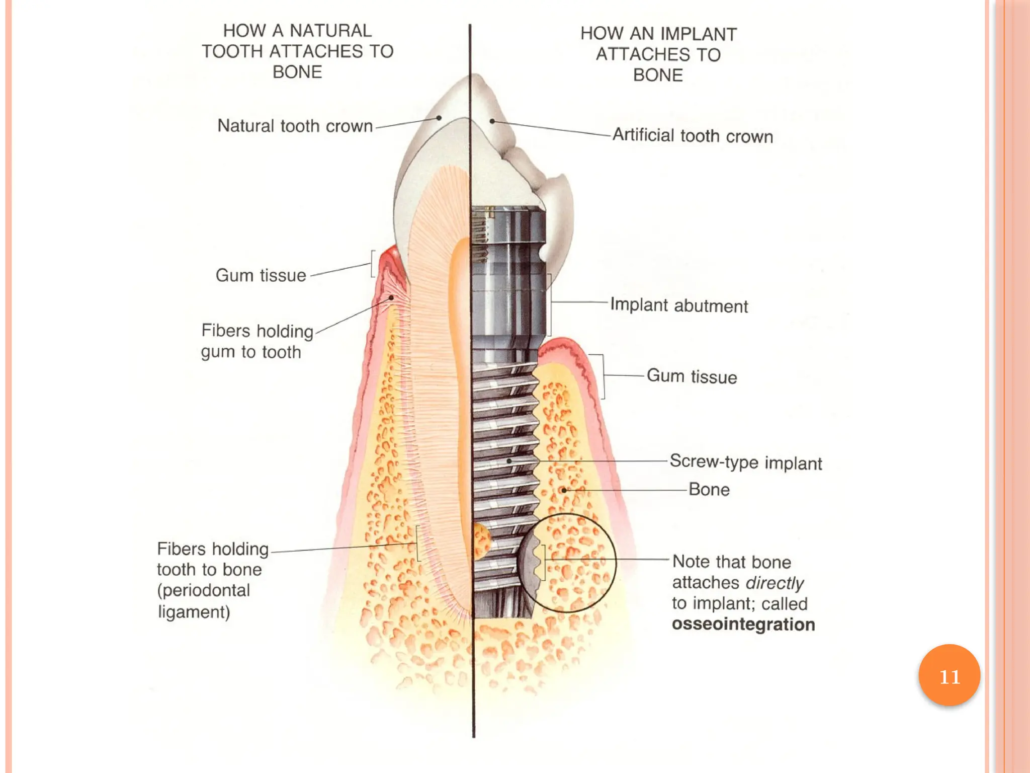
OSSEOINTEGRATION
A Swedishorthopedic surgeon, Prof Branemark, in
1952 accidentally discovered osseointegration.
When pure Ti comes in contact with the living bone
tissue the two literally grow together to form a
permanent biological adhesion.
Functional ankylosis- also called
5.
5
Factors for successfulosseointegration.
Biocompatible material- Ti, either commercially pure
or in certain alloys.
Prrimary implant stability- it should be precisely
adapted to the prepared bony site
Atraumatic surgery to minimize tissue damage
An immobile, undisturbed healing phase.
6.
6
TITANIUM
Biocompatibility isdue to its surface oxide
When exposed to air it forms a dense 4-nm layer of
Titanium dioxide TiO2 - chemically stable and very
corrosion-resistant.
4 grades of commercially pure titanium-differing with
percentage of trace impurities in the metal.The
greater the contaminants the harder the metal.
Grade 4 cpTi - commonly used for dental implants.
7.
7
Grade 5-Titanium alloy- Ti6Al4V.Offers equal
biocompatibility but better tensile strength and
fracture resistance than cpTi.
Zirconia- similar in biocompatibility, improved
cosmetics, fracture resistance lower,can be used as
only one piece.
8.
8
STEPS OF OSSEOINTEGRATION
Woven bone is quickly formed in the gap between the
implant and the bone.It has low biomechanical
capacity,- the occlusal load should be controlled
After 1 to 2 months, under the effect of load, the
woven bone will slowly transform into lamellar bone
9.
9
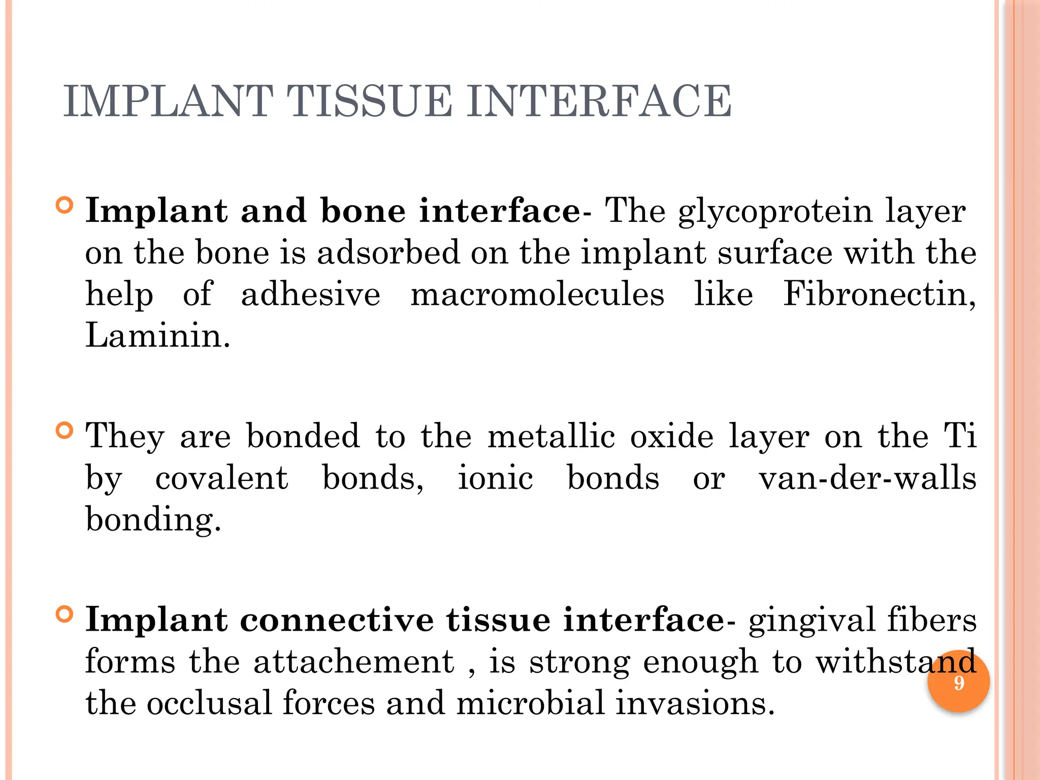
IMPLANT TISSUE INTERFACE
Implant and bone interface- The glycoprotein layer
on the bone is adsorbed on the implant surface with the
help of adhesive macromolecules like Fibronectin,
Laminin.
They are bonded to the metallic oxide layer on the Ti
by covalent bonds, ionic bonds or van-der-walls
bonding.
Implant connective tissue interface- gingival fibers
forms the attachement , is strong enough to withstand
the occlusal forces and microbial invasions.
10.
10
Implant epithelialinterface-Epithelium is
attached to implant surface through
hemidesomosomes and glycoproteins and considered
as Biologic seal.
It forms a sulcus depth of 3 to 4 mm.
13
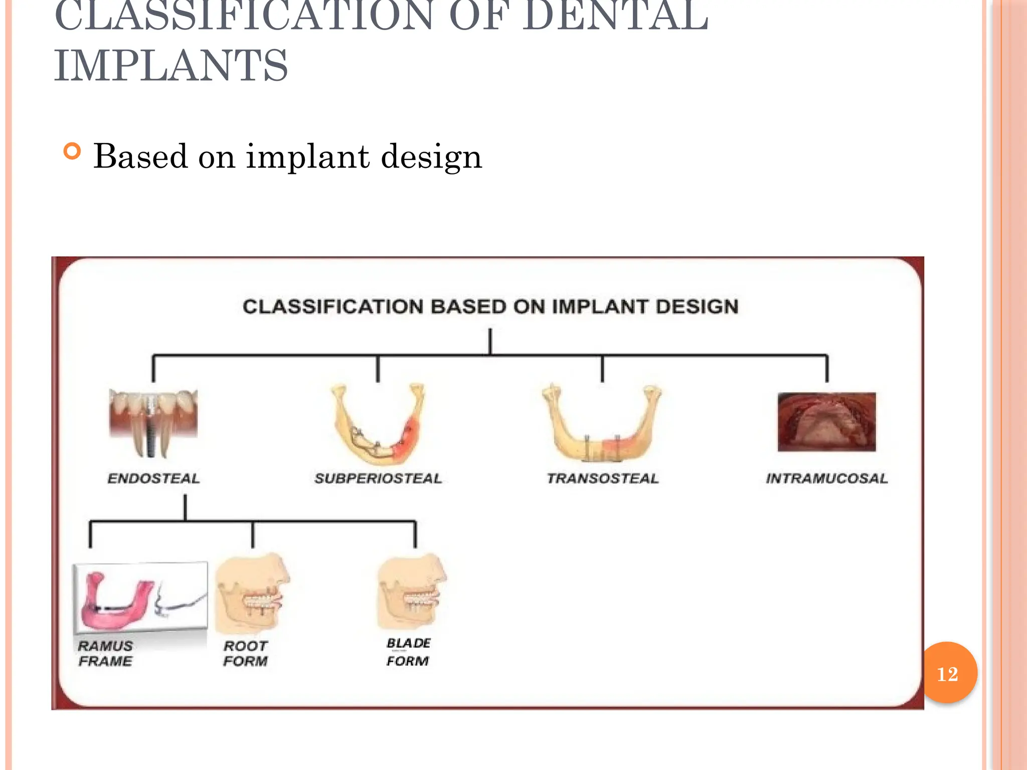
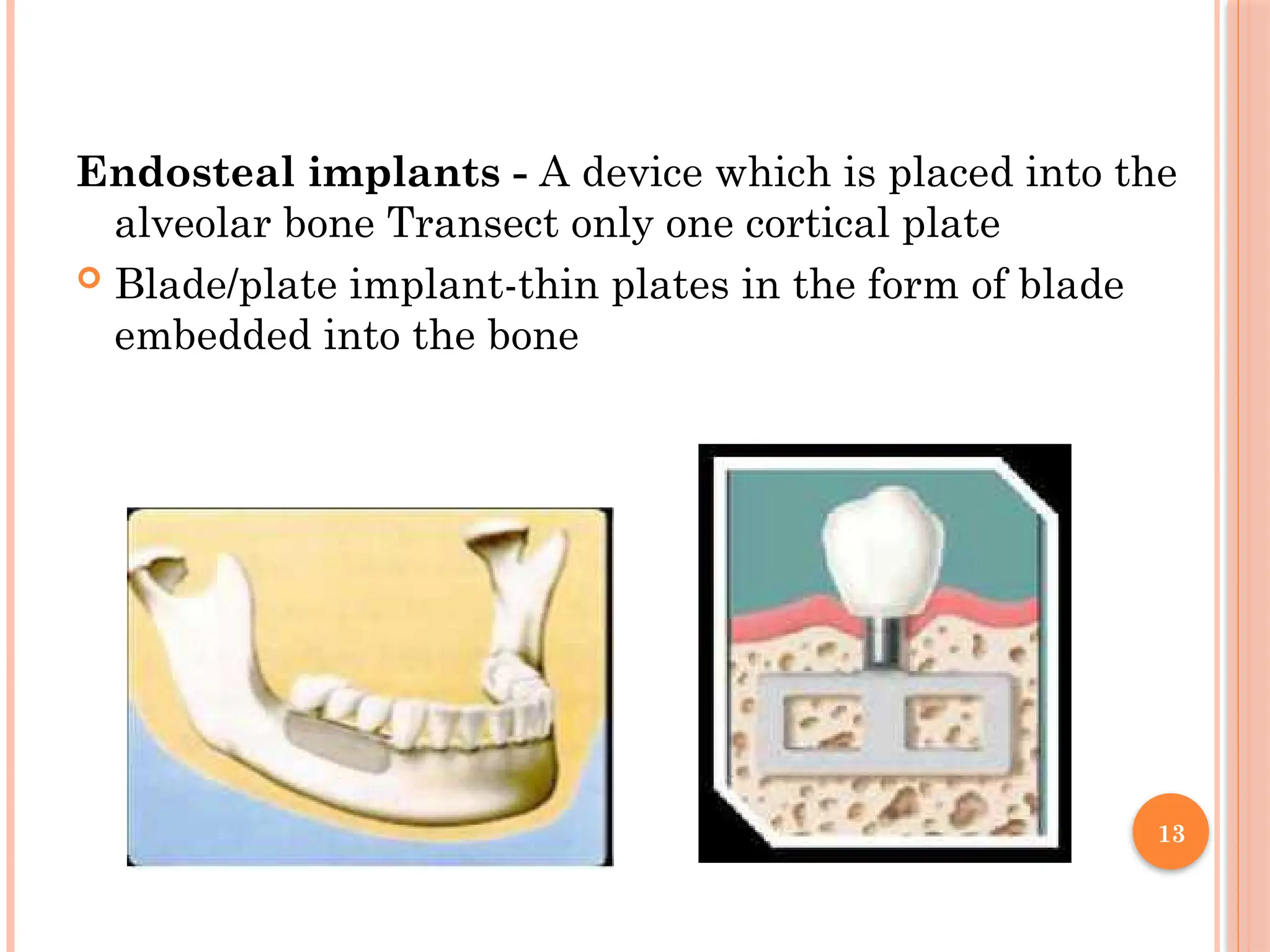
Endosteal implants -A device which is placed into the
alveolar bone Transect only one cortical plate
Blade/plate implant-thin plates in the form of blade
embedded into the bone
14.
14
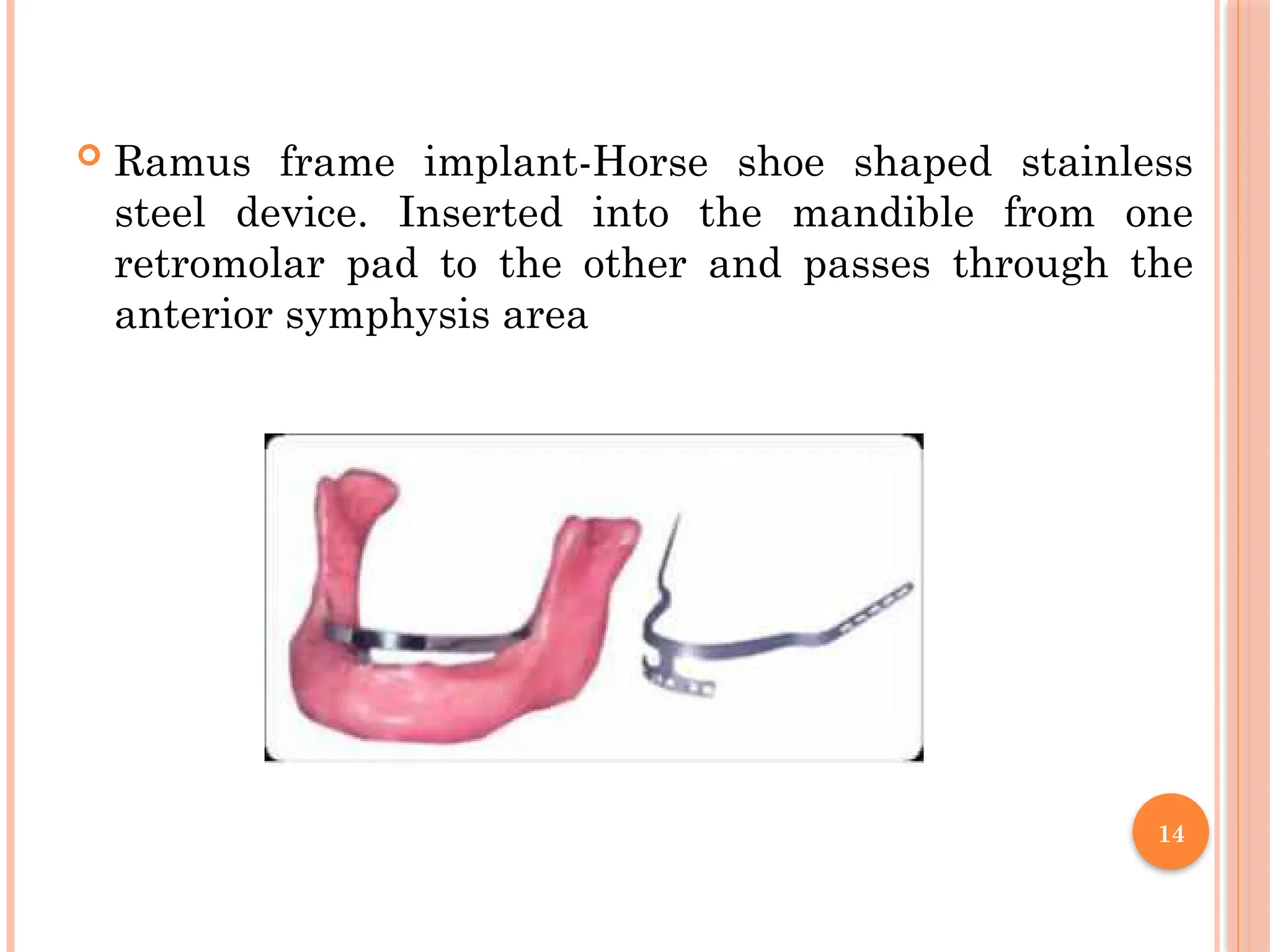
Ramus frameimplant-Horse shoe shaped stainless
steel device. Inserted into the mandible from one
retromolar pad to the other and passes through the
anterior symphysis area
15.
15
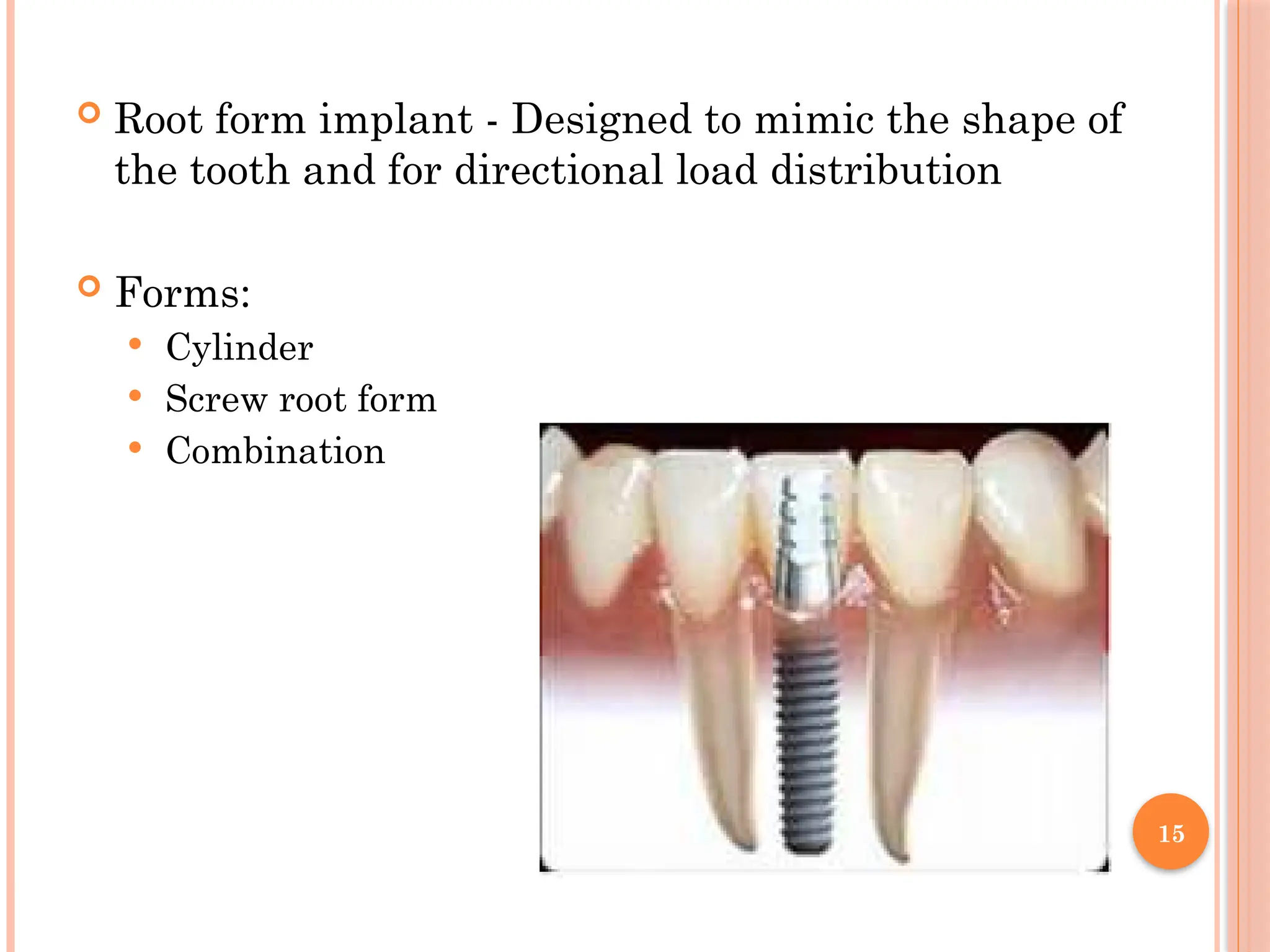
Root formimplant - Designed to mimic the shape of
the tooth and for directional load distribution
Forms:
Cylinder
Screw root form
Combination
16.
16
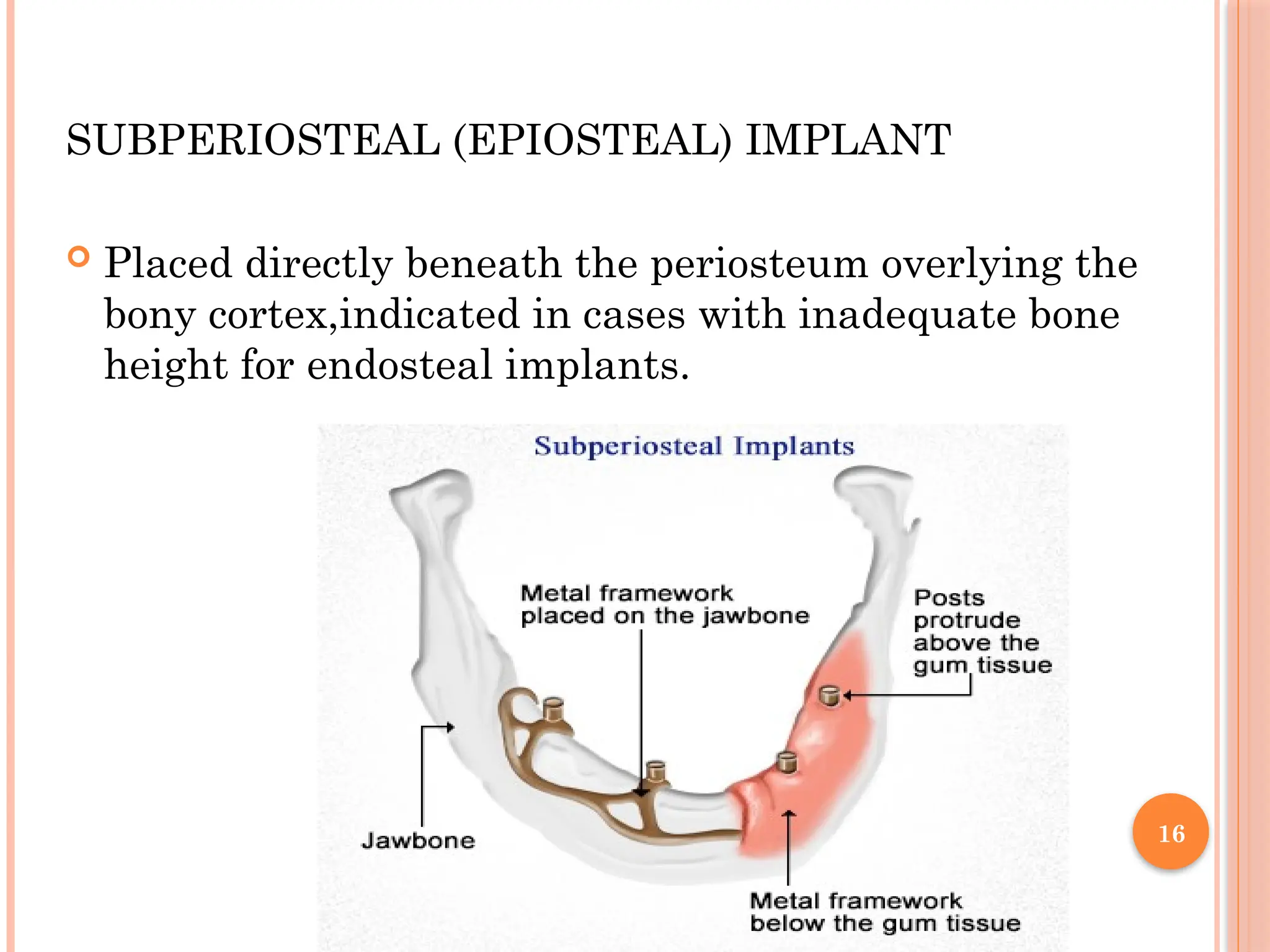
SUBPERIOSTEAL (EPIOSTEAL) IMPLANT
Placed directly beneath the periosteum overlying the
bony cortex,indicated in cases with inadequate bone
height for endosteal implants.
17.
17
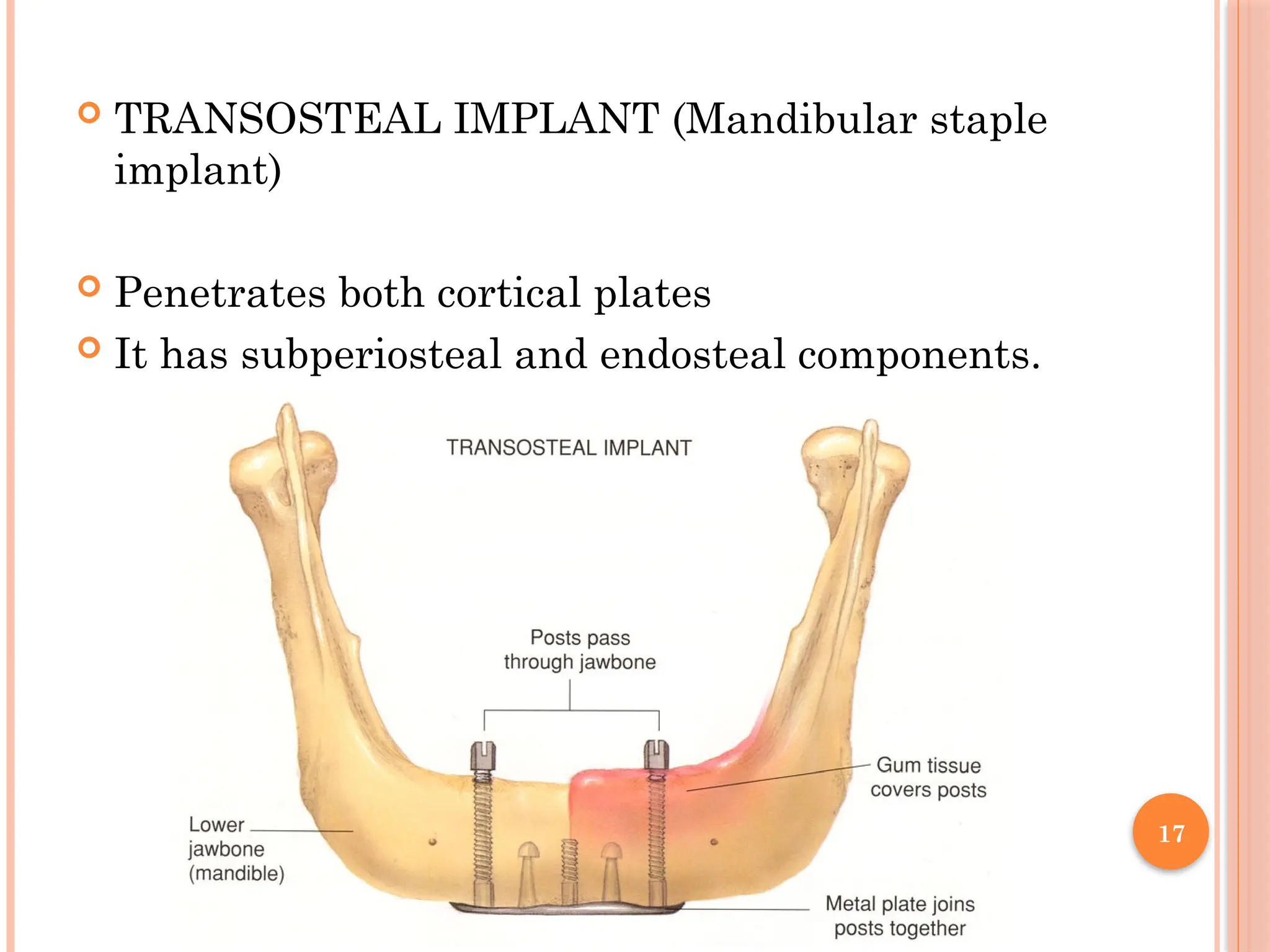
TRANSOSTEAL IMPLANT(Mandibular staple
implant)
Penetrates both cortical plates
It has subperiosteal and endosteal components.
Based onsurgical timing
1. Immediate post-extraction implant.
2. Delayed immediate post-extraction implant. (2 weeks
to 3 months after extraction).
3. Late implantation (3 months or more after tooth
extraction).
22.
22
According tothe timing of loading of dental
implants
1. Immediate loading procedure.
2. Early loading (1 week to 12 weeks).
3. Delayed loading (over 3 months)
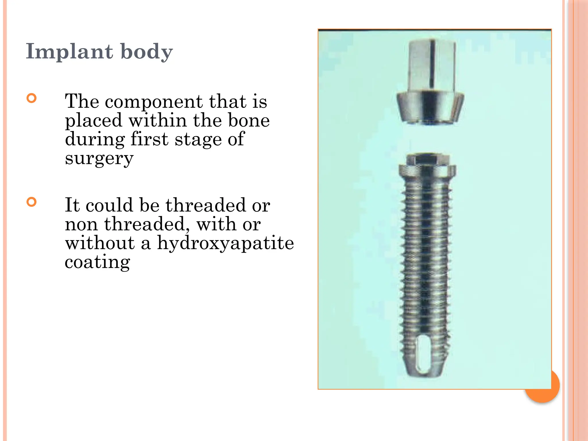
Implant body
Thecomponent that is
placed within the bone
during first stage of
surgery
It could be threaded or
non threaded, with or
without a hydroxyapatite
coating
25.
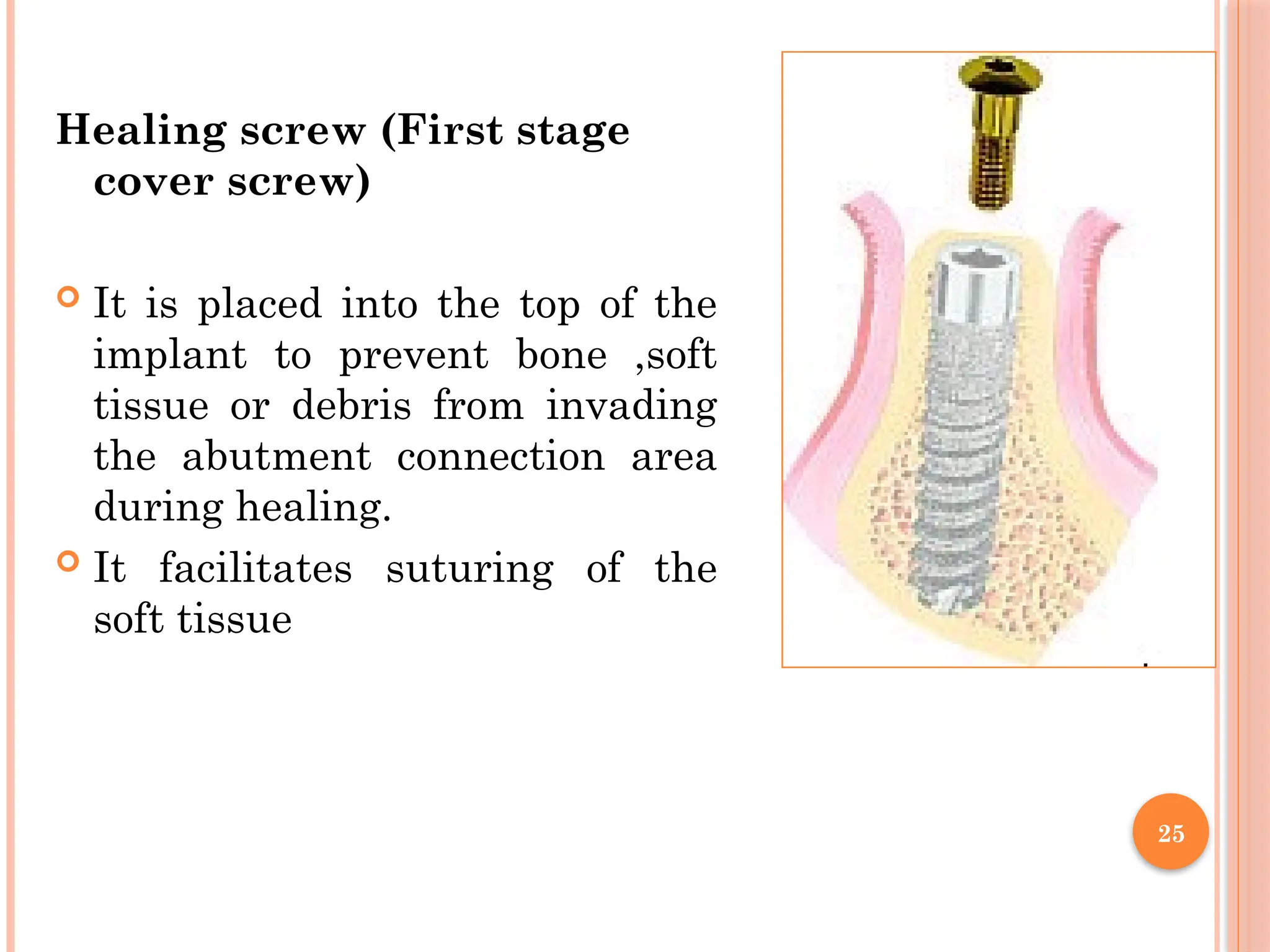
Healing screw (Firststage
cover screw)
It is placed into the top of the
implant to prevent bone ,soft
tissue or debris from invading
the abutment connection area
during healing.
It facilitates suturing of the
soft tissue
25
26.
26
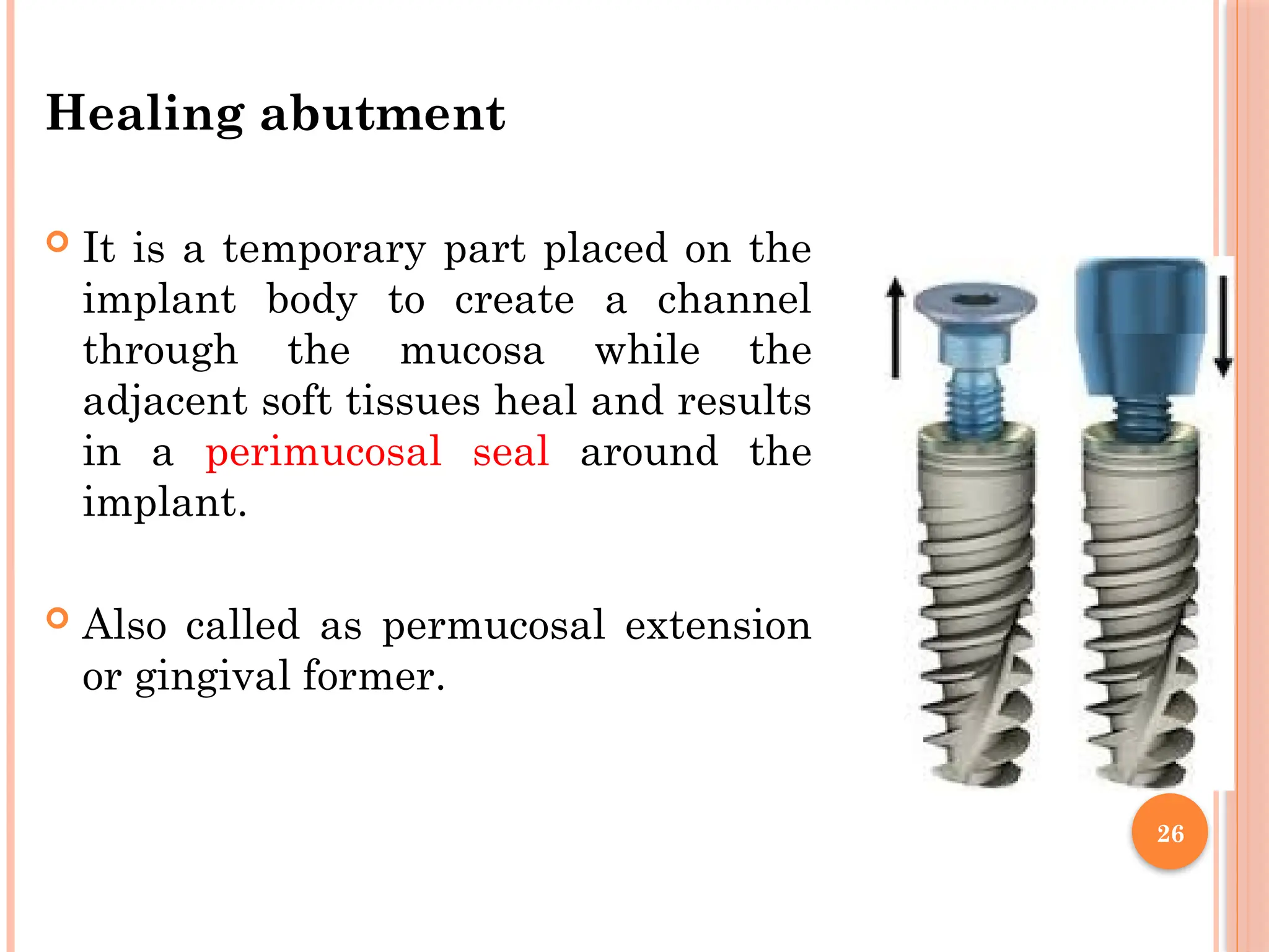
Healing abutment
Itis a temporary part placed on the
implant body to create a channel
through the mucosa while the
adjacent soft tissues heal and results
in a perimucosal seal around the
implant.
Also called as permucosal extension
or gingival former.
27.
27
Impression coping (impressioncap)
It is used to transfer the position of the implant body or
the abutment to the working cast.
The dentist screws the impression coping to the real
implant body and then takes an impression.
The impression coping remain fixed in the impression
material and lab analogue is added prior to dispatching
to the lab.
28.
28
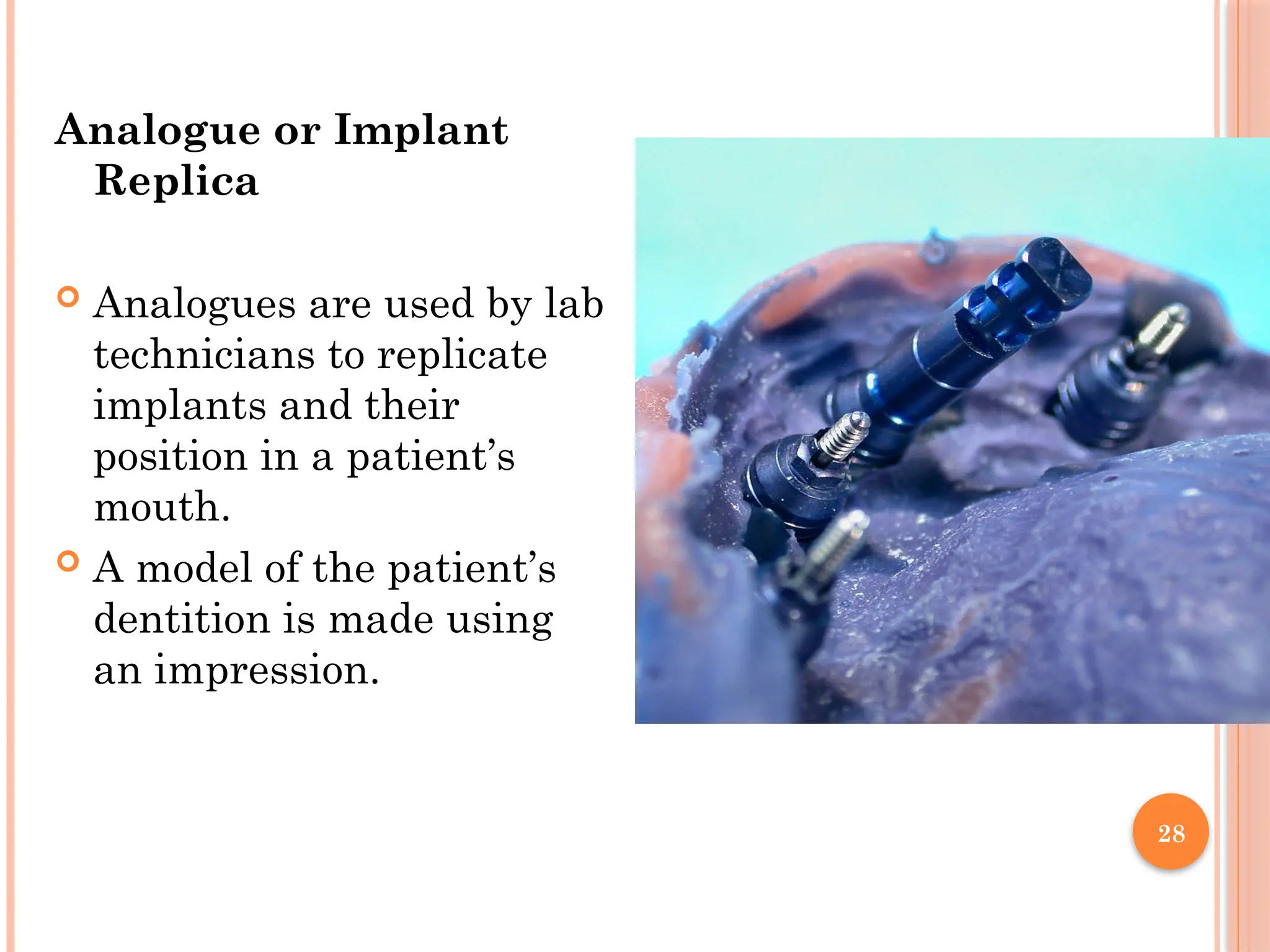
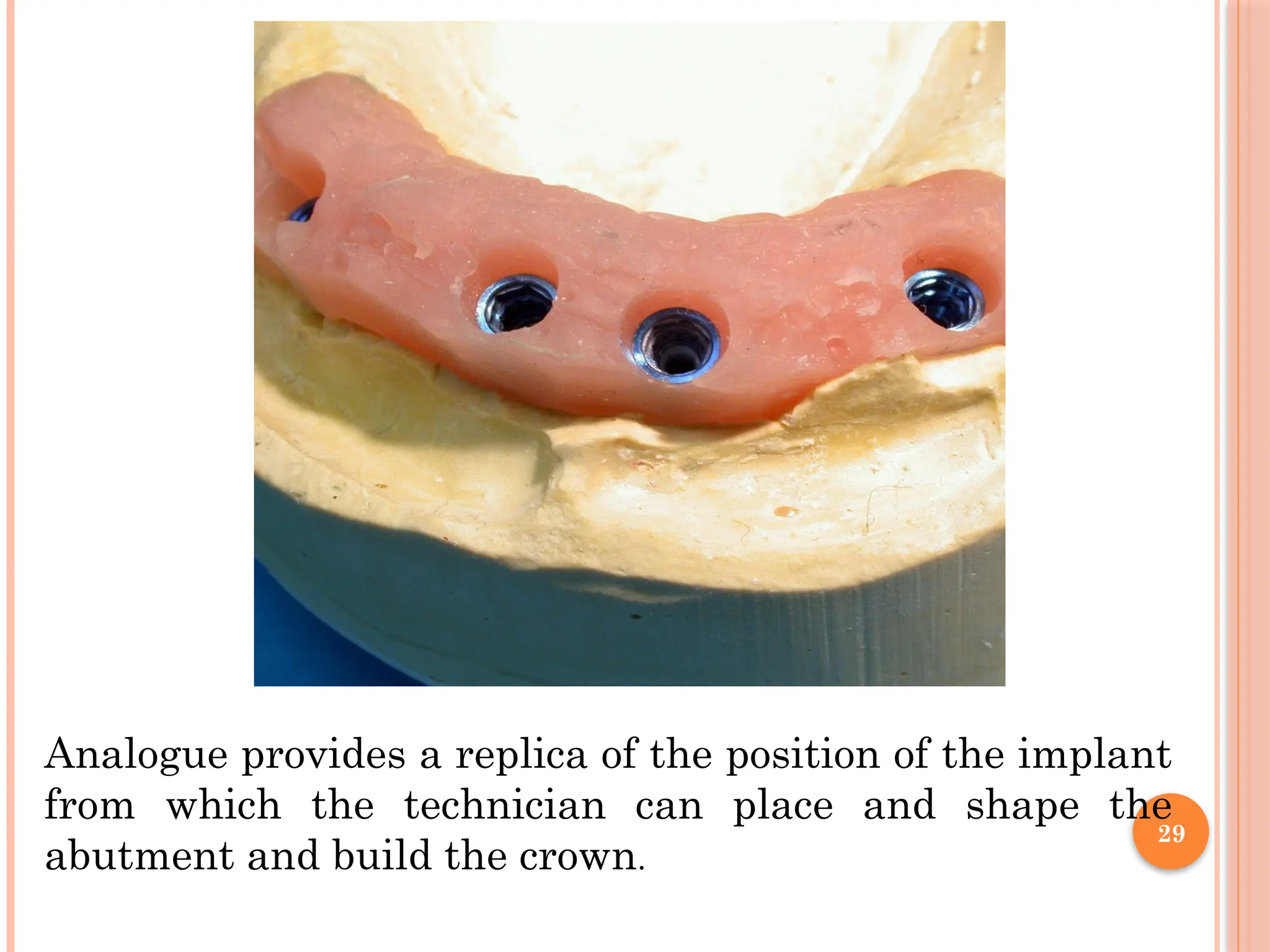
Analogue or Implant
Replica
Analogues are used by lab
technicians to replicate
implants and their
position in a patient’s
mouth.
A model of the patient’s
dentition is made using
an impression.
29.
29
Analogue provides areplica of the position of the implant
from which the technician can place and shape the
abutment and build the crown.
30.
30
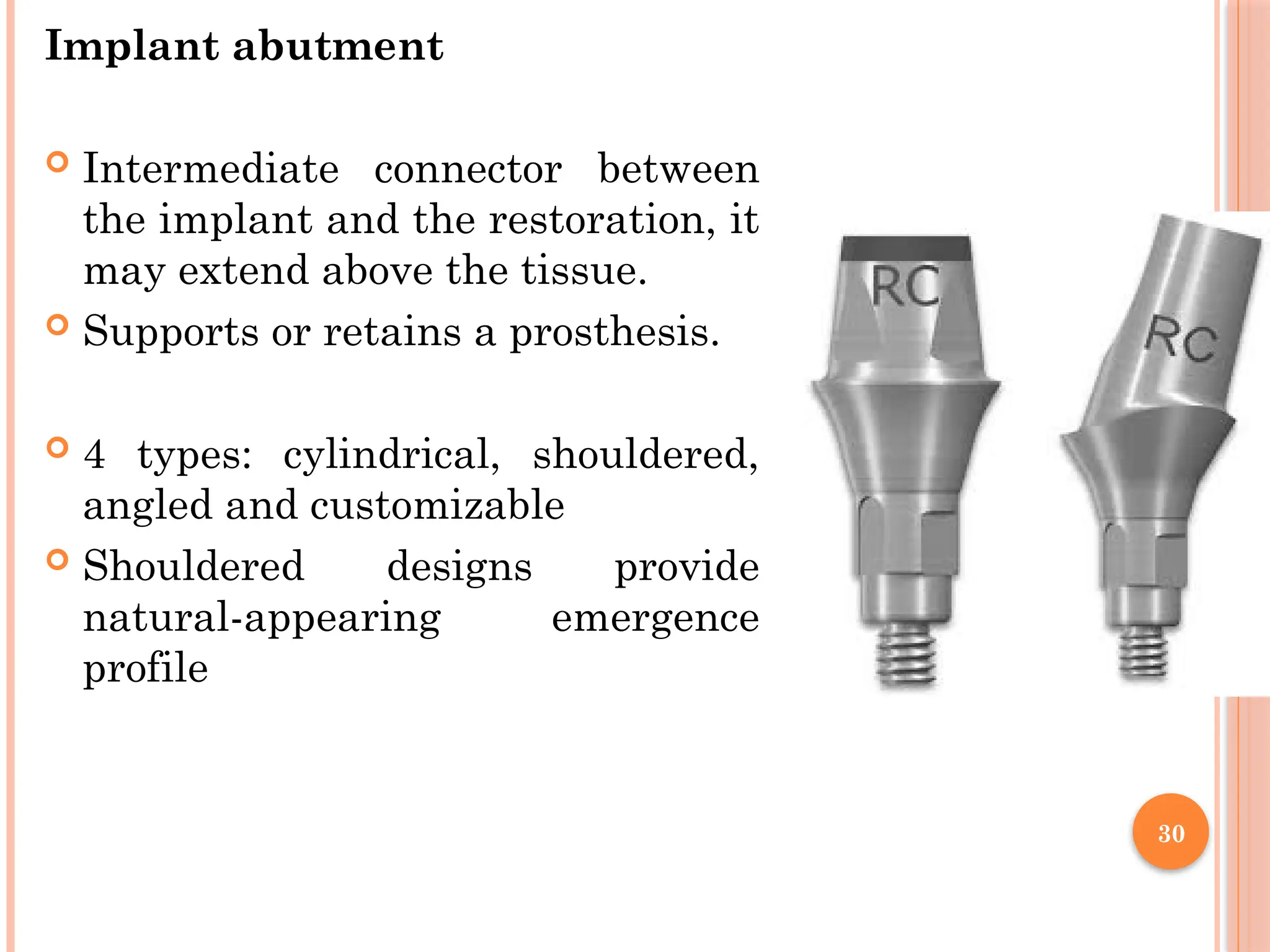
Implant abutment
Intermediateconnector between
the implant and the restoration, it
may extend above the tissue.
Supports or retains a prosthesis.
4 types: cylindrical, shouldered,
angled and customizable
Shouldered designs provide
natural-appearing emergence
profile
31.
31
TREATMENT PLANNING
Clinical evaluation
Medical history
Current dentoalveolar condition
Local evaluation of site for implant placement -Alveolar bone
height, width, and jaw relationship and prosthetic restorability.
Intraoral bone mapping - probe through the soft tissue to
assess the thickness of the soft tissues and measure the bone
dimensions at the proposed surgical site.
Patient's expectations – Reasonable or not
Oral hygiene status
Study model analysis
To determine
Clinical length of the prosthetic crown that will be
supported by the implant. (Crown-implant ratio).
Inter arch distance.
The implant axis- it should be parallel to the axis of
adjacent natural teeth.
Number and size of implants.
34.
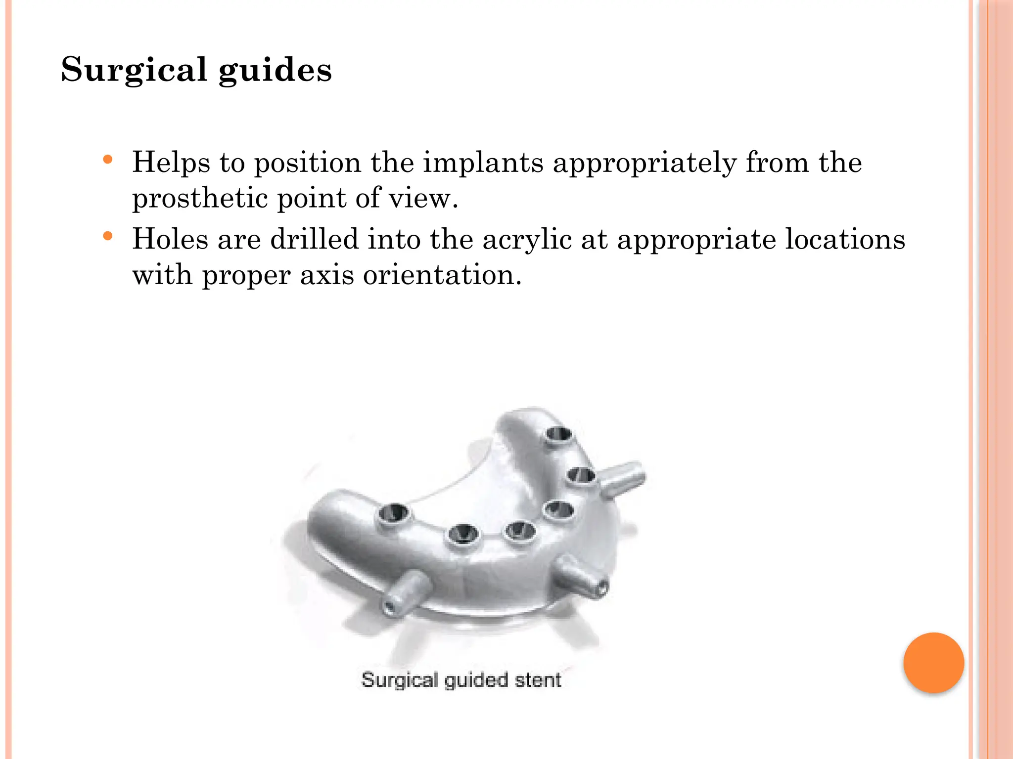
Surgical guides
Helpsto position the implants appropriately from the
prosthetic point of view.
Holes are drilled into the acrylic at appropriate locations
with proper axis orientation.
35.
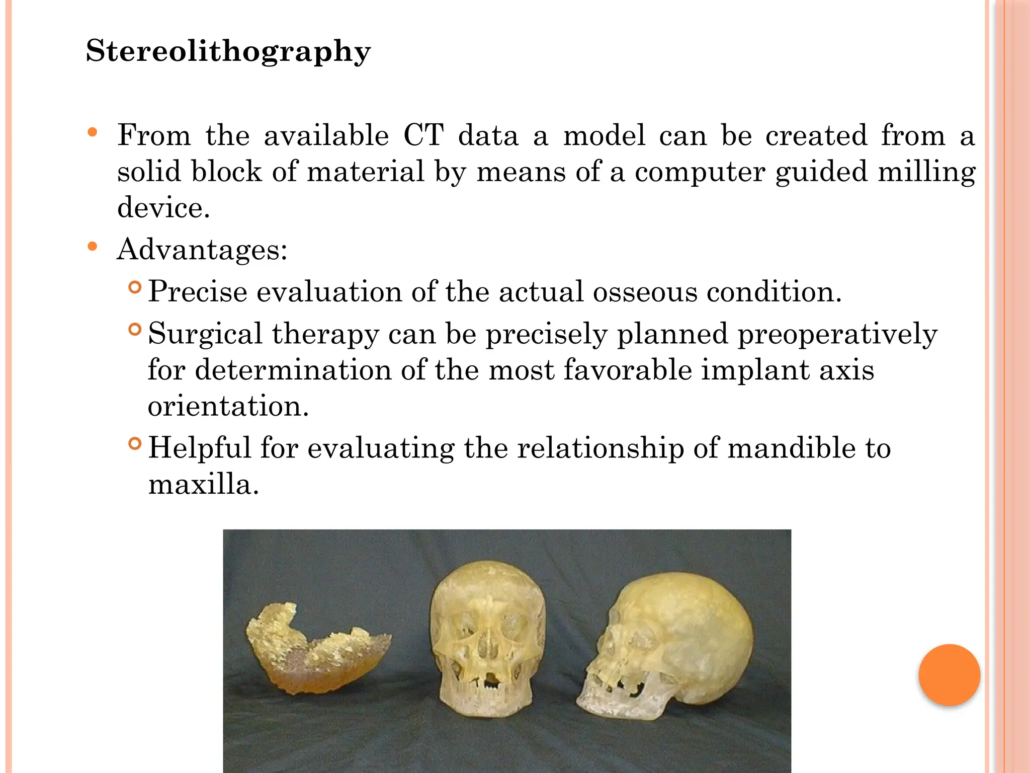
Stereolithography
From theavailable CT data a model can be created from a
solid block of material by means of a computer guided milling
device.
Advantages:
Precise evaluation of the actual osseous condition.
Surgical therapy can be precisely planned preoperatively
for determination of the most favorable implant axis
orientation.
Helpful for evaluating the relationship of mandible to
maxilla.
36.
36
FACTORS AFFECTING
TREATMENT
Implant position,Number,Sizeand design depends on
Implant Prosthesis design- Implant supported denture,
over denture or FPD.
Patient force factors- Para functional habits,
masticatory forces, Crown height,Occlusion.
Bone density
37.
37
BONE EVALUATION
Boneheight - Minimum for long term survival is 10 mm It
is 12 mm in the posterior mandible because of nerve
proximity.
Bone width - The minimal width should be 6 to 7 mm.
Bone length -
length refers to mesio distal distance
1.5 mm from adjacent tooth & 3 mm from adjacent
implant, Should be 2 mm from adjacent anatomical
barrier.
So a 5 mm implant requires atleast 8 mm length of the
bone
38.
38
Bone angulation
Ideally it is aligned with the forces of occlusion & is
parallel to the long axis of prosthodontic restoration.
Premolar region-10°
1 st Molar -15°
2 nd Molar-20-25°
For Wider ridge 30° is acceptable
39.
39
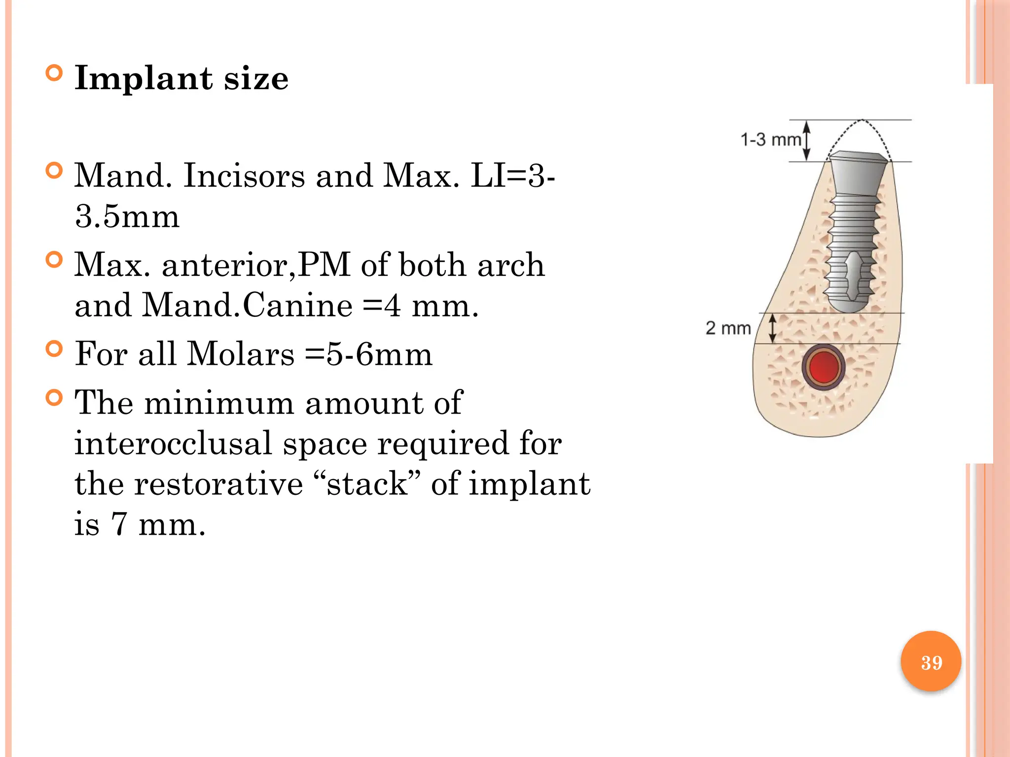
Implant size
Mand. Incisors and Max. LI=3-
3.5mm
Max. anterior,PM of both arch
and Mand.Canine =4 mm.
For all Molars =5-6mm
The minimum amount of
interocclusal space required for
the restorative “stack” of implant
is 7 mm.
40.
40
Crown :Implant
Most ideal – 1 : 2
More common – 1 : 1.5
Minimum requirement – 1 : 1
As the Crown : Implant increases the number of implants
& / or wider implants should be inserted to counteract the
increase in stress.
41.
41
Bone density
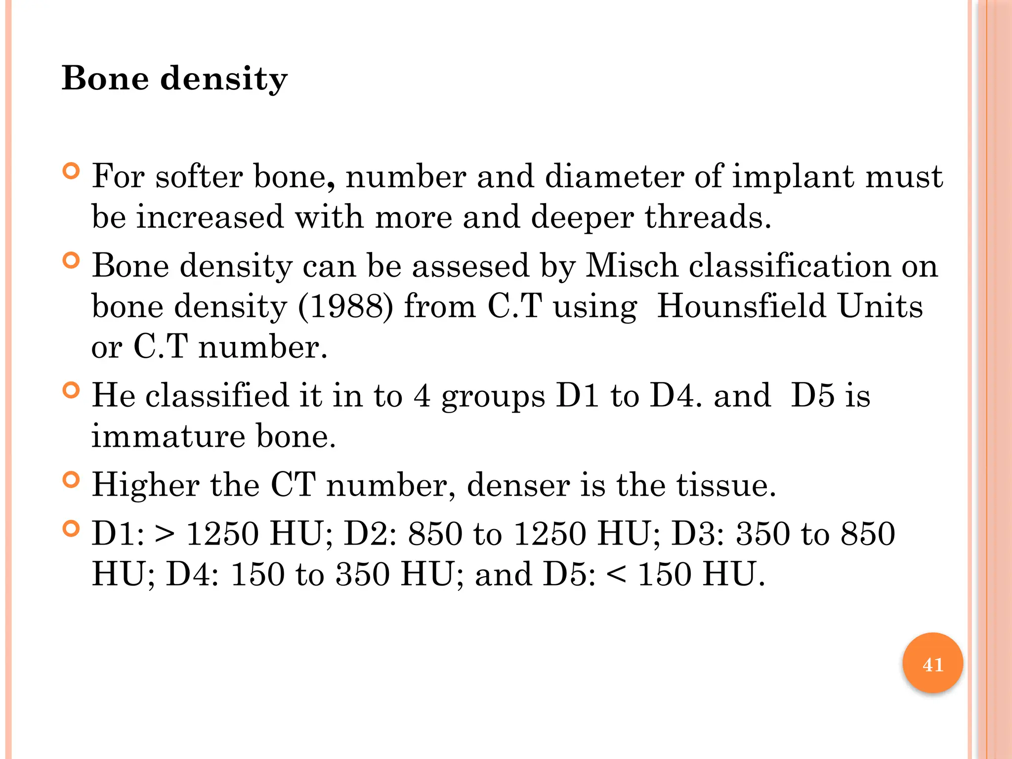
Forsofter bone, number and diameter of implant must
be increased with more and deeper threads.
Bone density can be assesed by Misch classification on
bone density (1988) from C.T using Hounsfield Units
or C.T number.
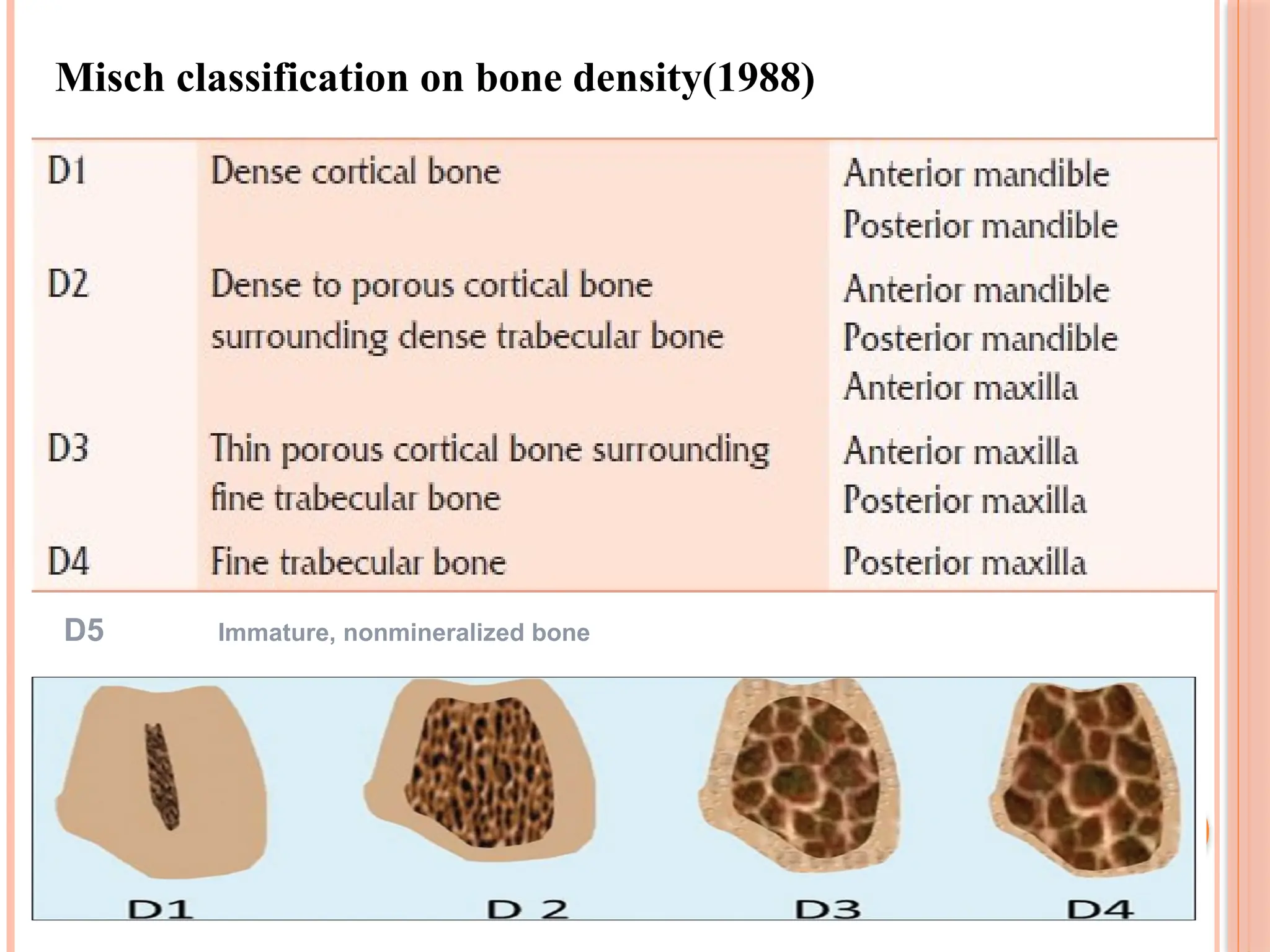
He classified it in to 4 groups D1 to D4. and D5 is
immature bone.
Higher the CT number, denser is the tissue.
D1: > 1250 HU; D2: 850 to 1250 HU; D3: 350 to 850
HU; D4: 150 to 350 HU; and D5: < 150 HU.
43
Surgery canbe done in one stage or in two stage.
2 stage surgery-In first stage implants are surgically
placed under the gum and the patient is made to wait
for 6 months for osseointegration
2nd stage surgery is then performed where the healing
gingival former is placed and after a week of satisfactory
formation of a gingival collar for emergence profile is
achieved, impressions are made for implant prosthesis,
which may be cemented or screw retained
one-stage surgery –Implant is placed and left exposed
through the gum. In this case, a second stage surgery in
not needed
SURGICAL PROCEDURE
44.
44
Preoperative care
Surgicalsite preparation and isolation
Preoperative antibiotic prophylaxis - oral dose of 2
g penicillin V 1 hour before
Local anesthesia
Incision- Mid crestal incision with a margin of
1.5mm keratinized tissue buccally extending to the
sulcus of adjacent teeth
Flap should be reflected and elevated.
45.
45
Implant osteotomy
Afterthe bone is exposed the surgical guide template
is positioned.It directs the angulation of the implant.
A low-speed (1500-2000[rpm]),high-torque handpiece
and copious irrigation are necessary to prevent excess
thermal injury to the bone
46.
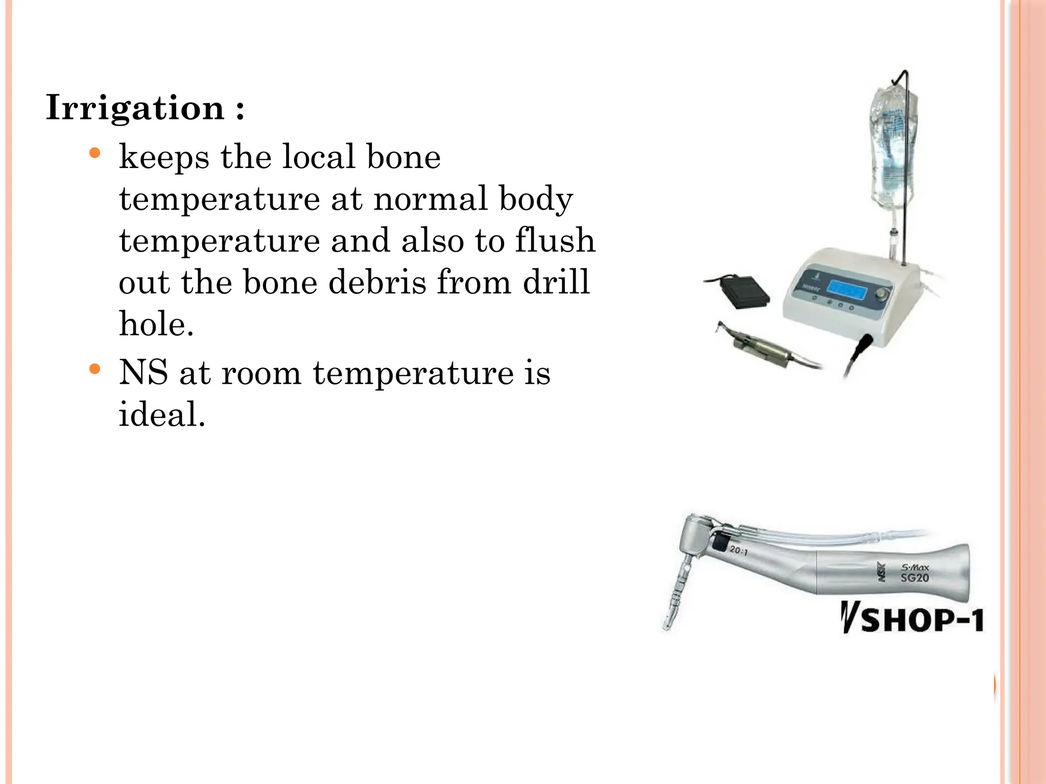
Irrigation :
keepsthe local bone
temperature at normal body
temperature and also to flush
out the bone debris from drill
hole.
NS at room temperature is
ideal.
47.
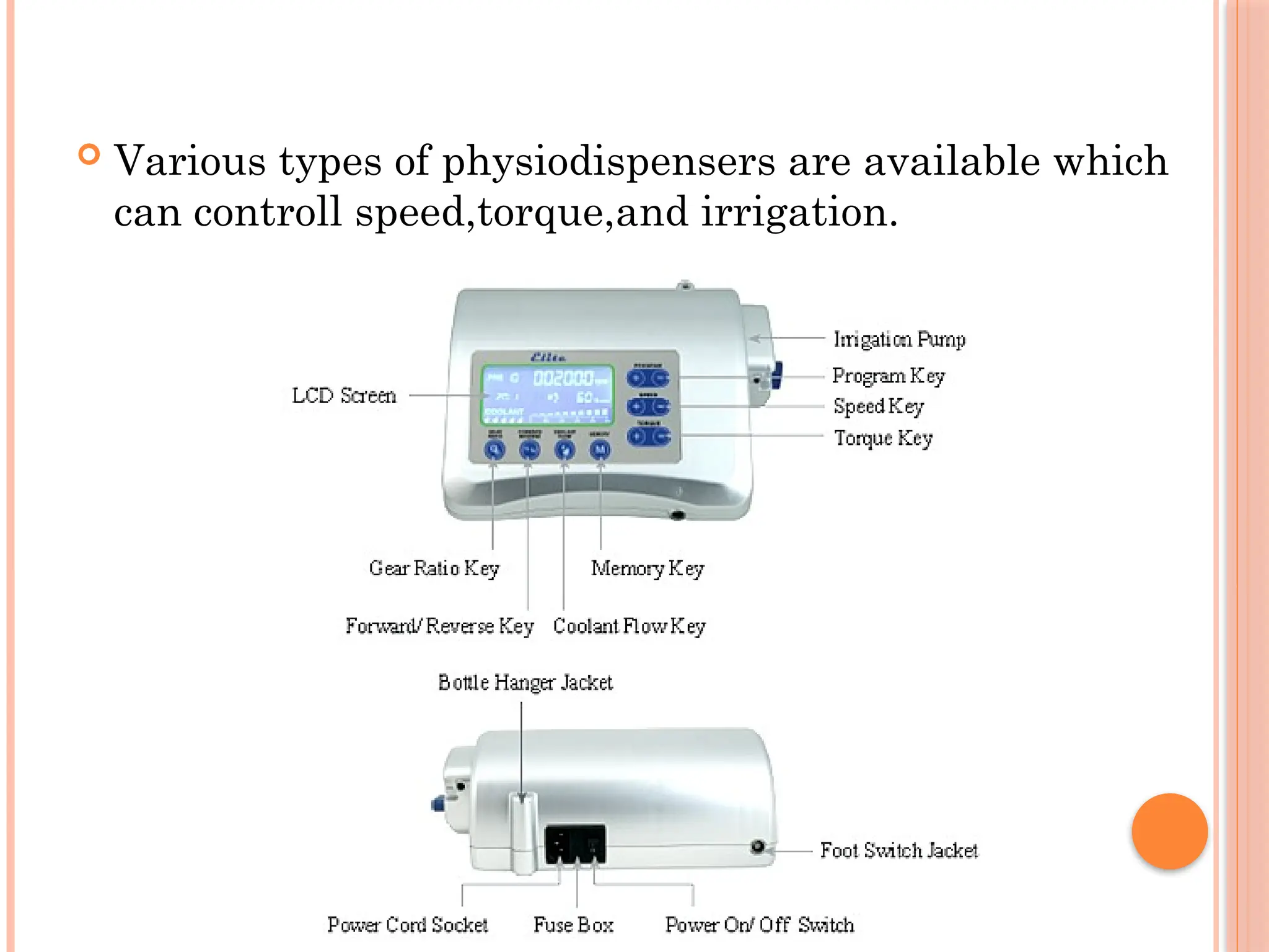
Various typesof physiodispensers are available which
can controll speed,torque,and irrigation.
48.
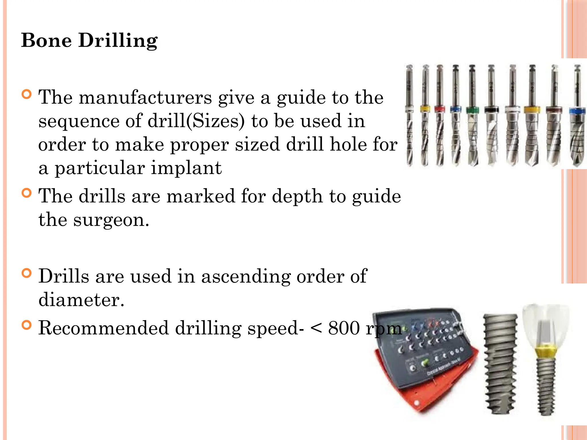
Bone Drilling
Themanufacturers give a guide to the
sequence of drill(Sizes) to be used in
order to make proper sized drill hole for
a particular implant
The drills are marked for depth to guide
the surgeon.
Drills are used in ascending order of
diameter.
Recommended drilling speed- < 800 rpm
49.
49
With theinitial drill, the center of the implant
recipient site is marked and the initial pilot hole is
prepared
A paralleling pin is placed in the initial preparation to
check alignment and angulation .
If it is appropriate,drill hole is sequentially enlarged to
dimensions of the implant.
After the desired depth and diameter of the recipient
site is accomplished, the implant can be placed.
50.
Implant placement
Afterfinal osteotomy, the site is lavaged and aspirated
to remove debris and blood.
For Ti implants, an uncontaminated surface oxide
layer is necessary to obtain osseointegration.So
touching with gloves, soft tissue or a dissimilar metal
should be avoided.
The implant is rotated with 30 rpm by low speed high
torque hand piece /hand ratchet.
It should be rigid with no mobility on slight
compression
51.
Post insertionradiograph- to evaluate the position ,
adjacent vital structure.
Cover screw is inserted. Flaps are sutured.
If implant position is not correct,it may be removed
and reinserted after several months later.
52.
52
Second stagesurgery
In second stage surgery in prefferably a ‘+’ shaped
incision is made in the overlying mucosa and the
cover screw is exposed and removed with a Hex
Driver, and is replaced with a gingival former and
is left for 7 to 17 days
The gingival former helps in formation of a
gingival collar around the future abutment which
helps in giving the final prosthesis a more natural
appearance.
53.
PROSTHETIC PHASE
Impression :
After the healing period,gingival former is
removed,impression copings are put onto the implant
and impression is taken by open/closed technique.
The implant analogue is fixed on the impression coping
and the impression is poured in die stone.
Now the analogue is seated in die with same
angulation as in bone.
Once the plaster is set the the coping is removed and
abutments are placed over the lab analogue.
Then the crown is fabricated over the abutment.
54.
54
After thefabrication of prosthesis, the abutment is
taken off the cast leaving the implant analogue in
the cast.
This abutment can now be transferred and screwed
onto the implant and prosthesis affixed to it (either
screwed or cemented to the abutment)
Occlusal adjustments are undertaken if required
55.
COMPLICATIONS
Intraoperative
Flaptear
Insufficient irrigation
Perforation of buccal or lingual cortex
Inferior alveolar nerve injury
Implant/Drill impinges on adjacent tooth root
Perforation of maxillary sinus
Perforation of pyriform fossa base
Lack of primary stability of implants
Fracture of implant
Implant failure
Mobilityof implant during healing period
Pain , infection
Radiolucency around implant.
whatever the cause,the implant should be removed.
Grafting and reinsertion can be done after 8-10wks.
58.
COMPLEMENTARY PROCEDURES
Bonegrafting for implants- Done when the bone is
too narrow or too short to place an adequate sized
implant.
Sinus lift
Our sinuses are located in close proximity to the upper
posterior jaw bone. In some cases, the sinus floor
"dips" down, causing that area to lose bone height,then
a "sinus lift" procedure is necessary in order to
increase bone height.
59.
59
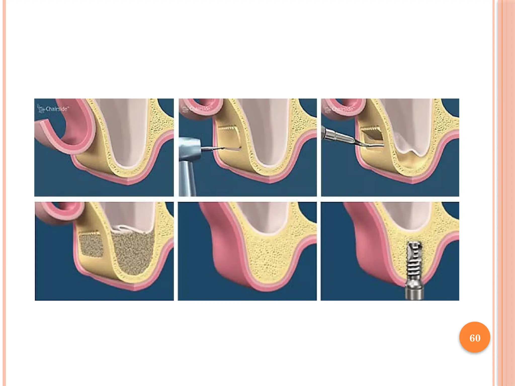
A corticalwindow 2 to 3 mm above the sinus floor
is created with round bur down to the membrane
of the sinus.
Careful in-fracture of the window with dissection
of the sinus membrane off the sinus floor creates
the space necessary for graft placement; the
Corticocancellous blocks may be placed in the
resulting defect.
CONCLUSION
Dental implantshave overall had high success rates,
but their placement and restoration still have the
boundaries of both biomedical science and art.
The effectiveness of different designs of implant-
supported prostheses as well as associated treatment
modalities leads to improvement in speech, function
and quality of life.
Editor's Notes
#30 Now abutments are casted along with crown in the lab.
![45
Implant osteotomy
After the bone is exposed the surgical guide template
is positioned.It directs the angulation of the implant.
A low-speed (1500-2000[rpm]),high-torque handpiece
and copious irrigation are necessary to prevent excess
thermal injury to the bone](https://image.slidesharecdn.com/dentalimplants1-251203171554-5b98ebc9/75/Denta-implants-and-it-applied-science-bm-45-2048.jpg)