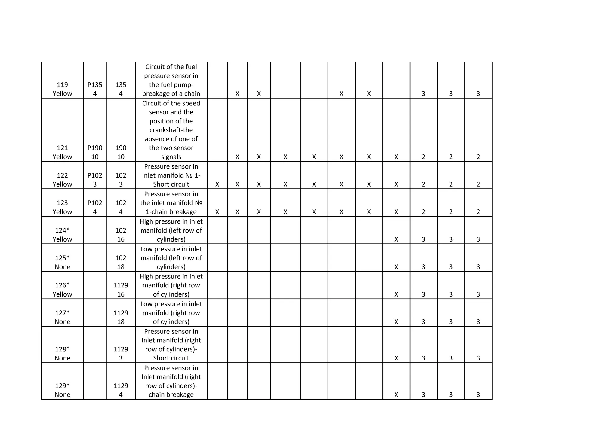
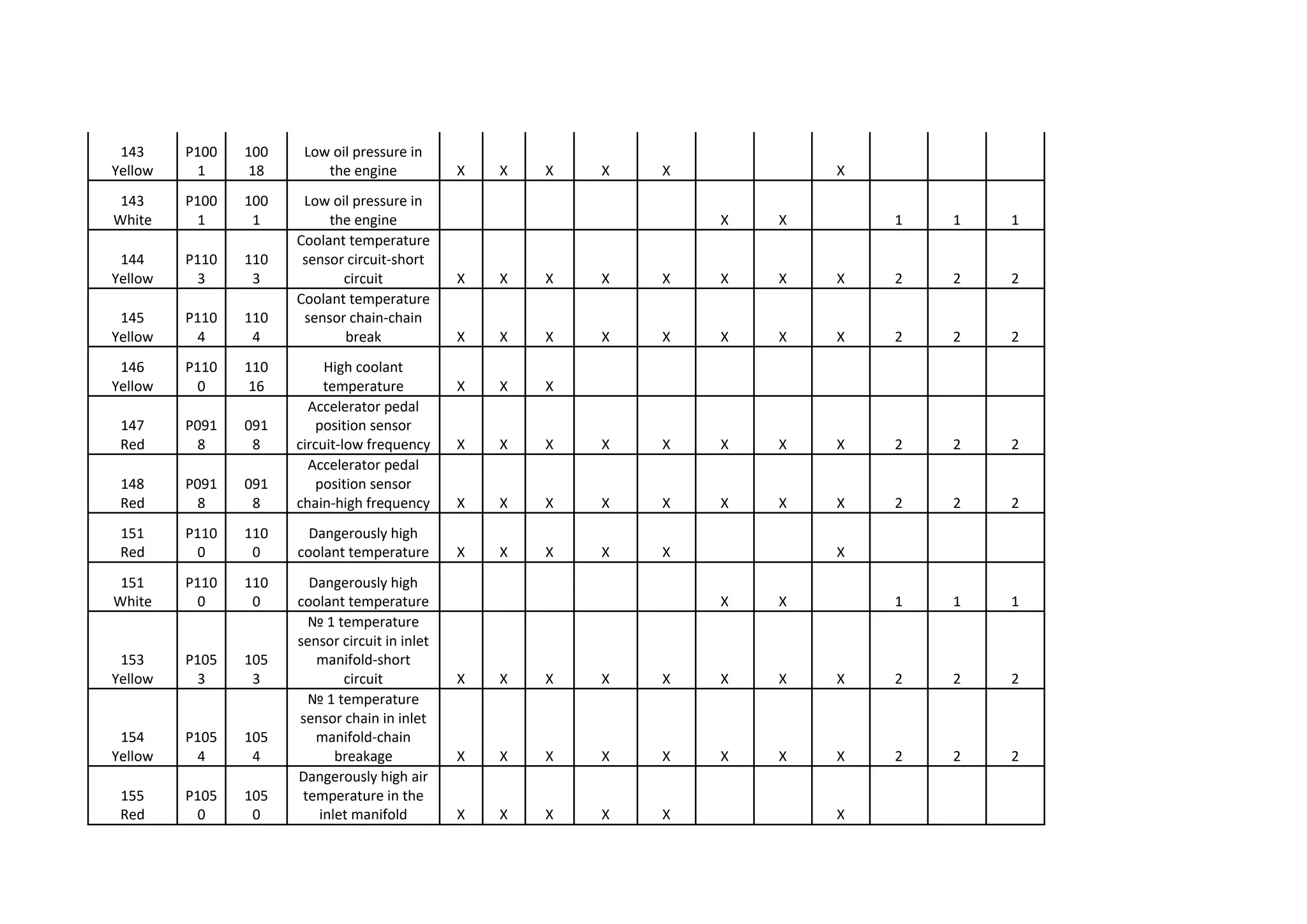
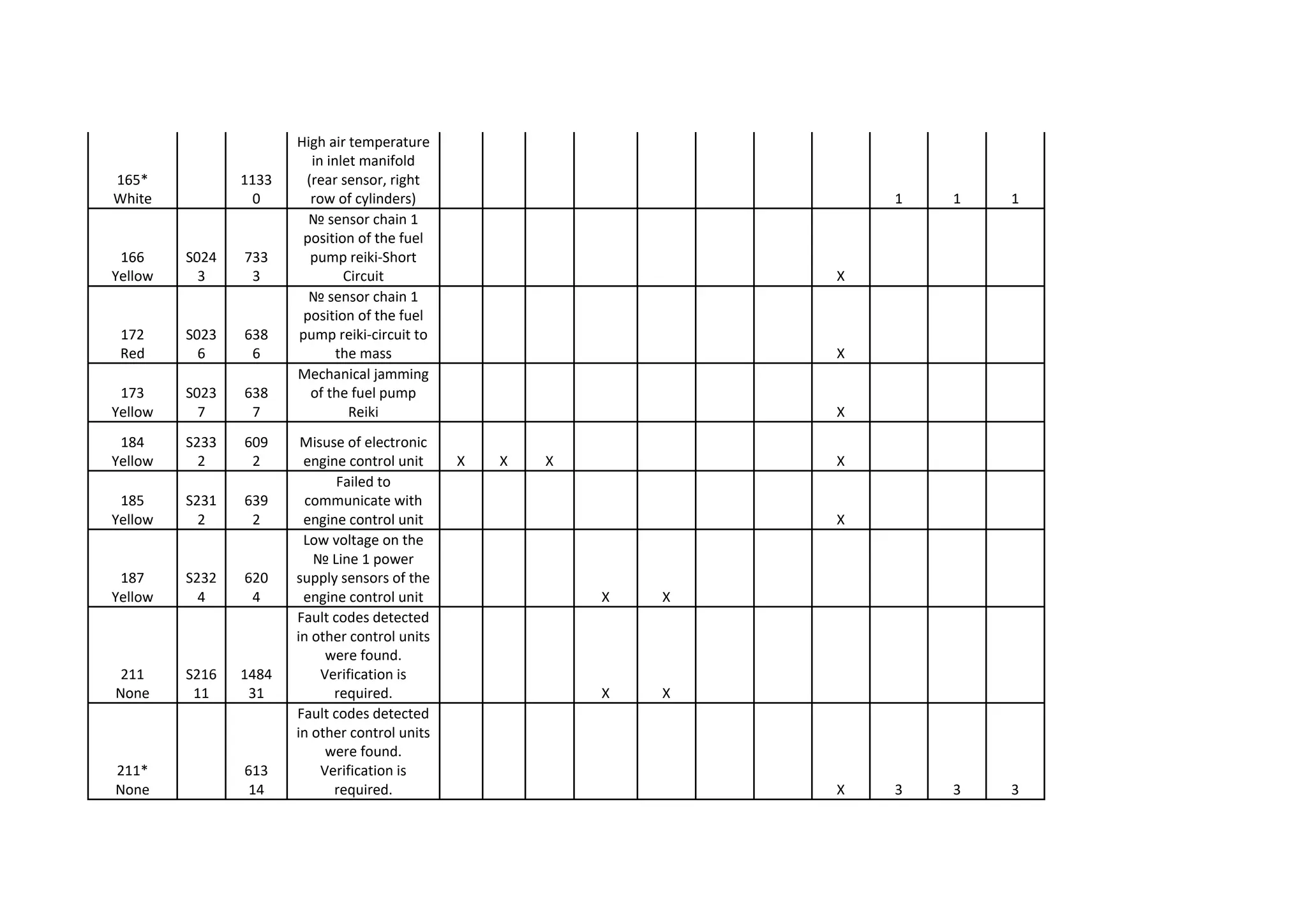
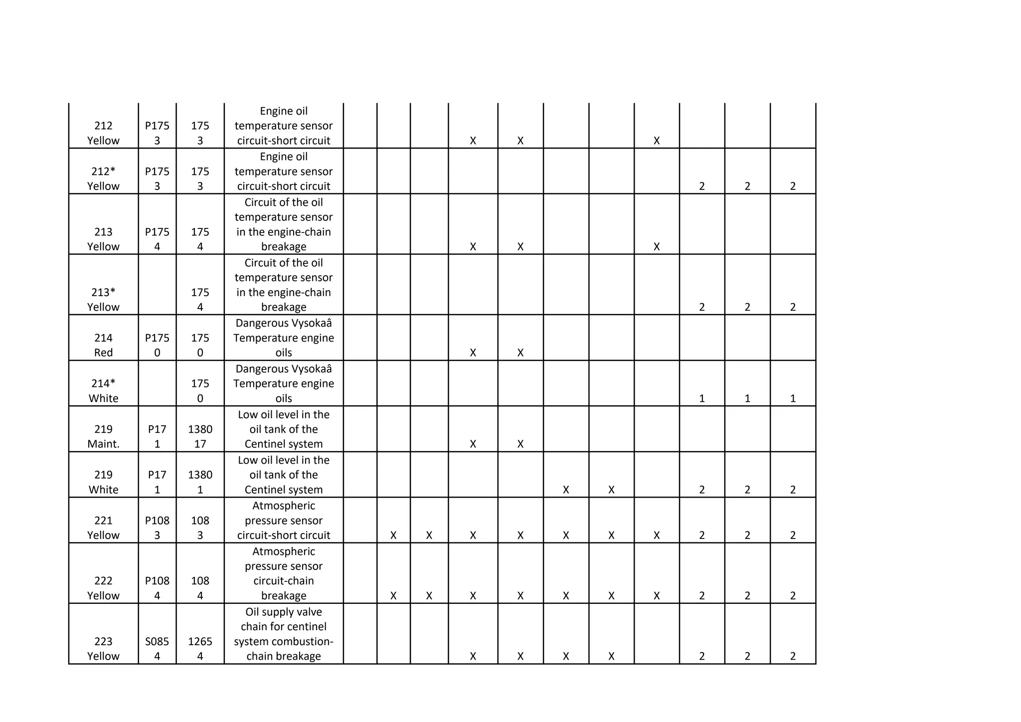
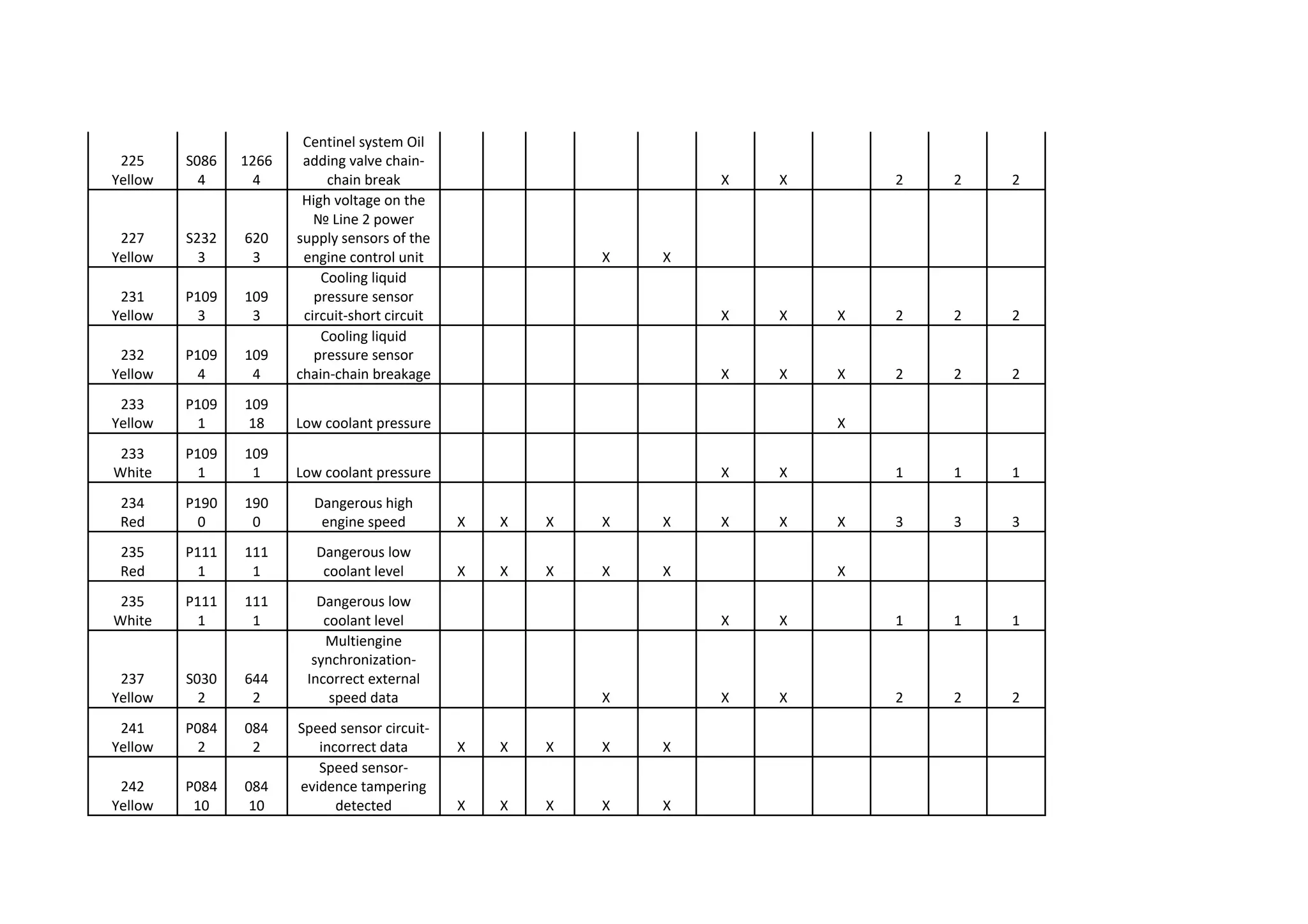
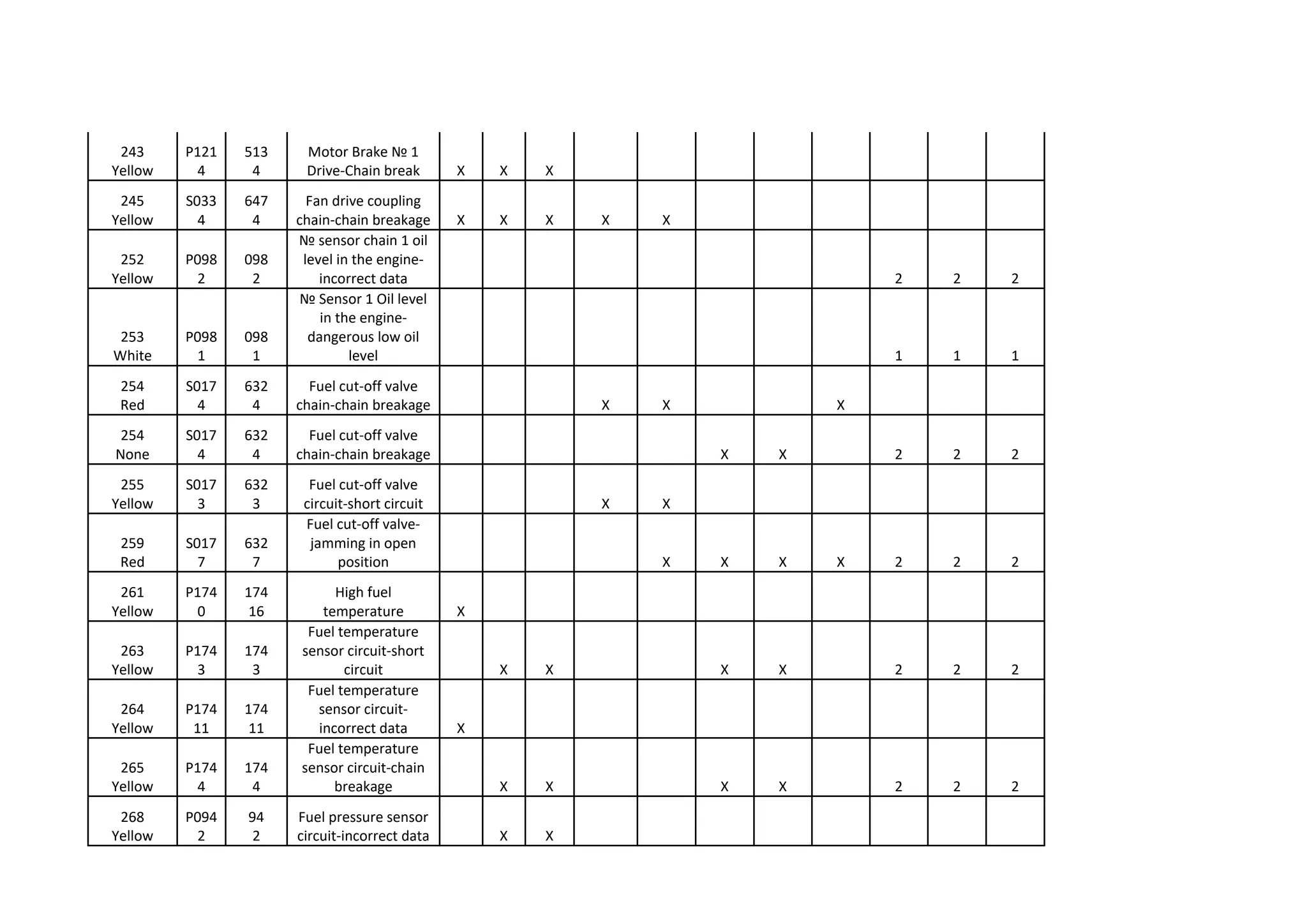
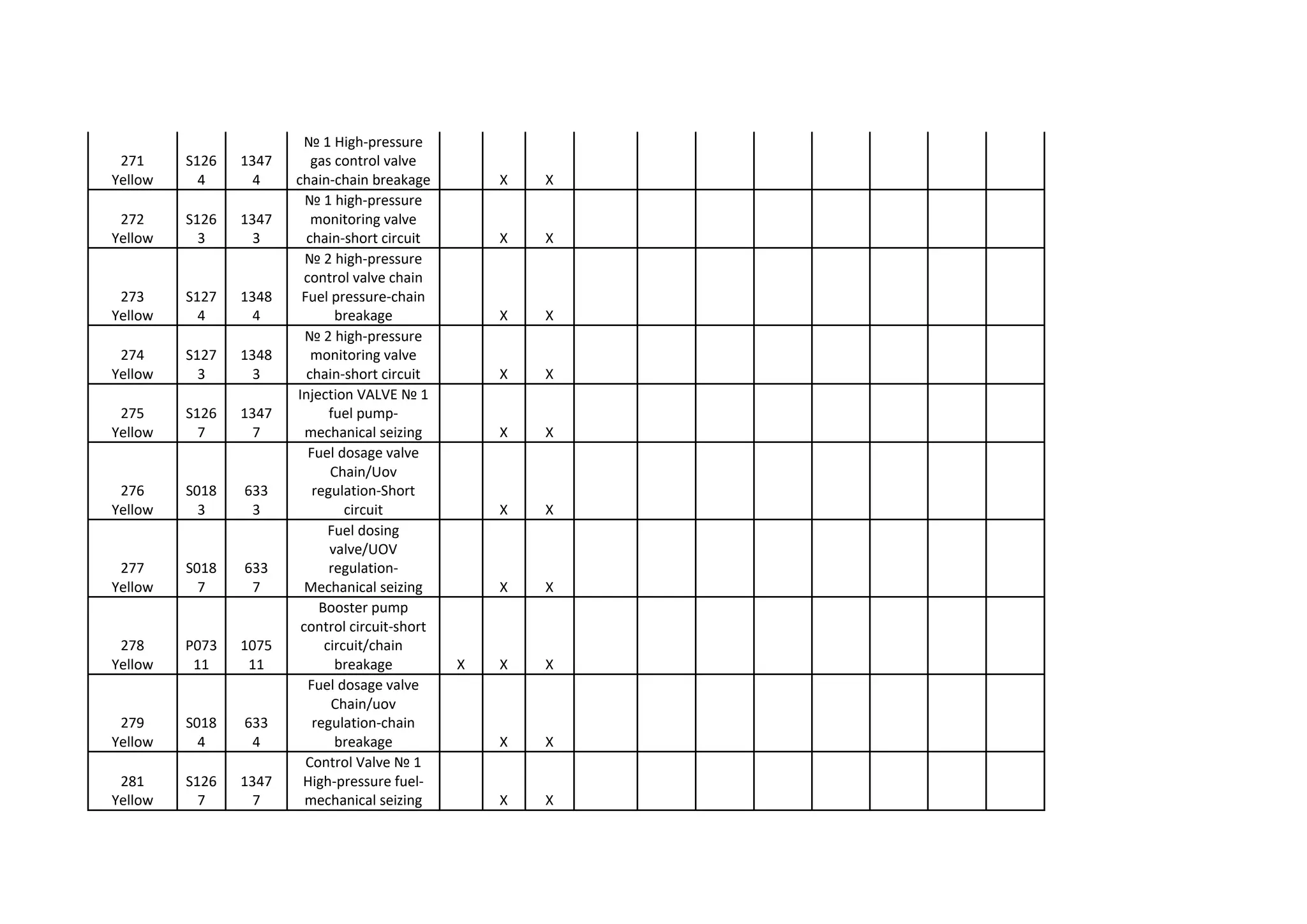
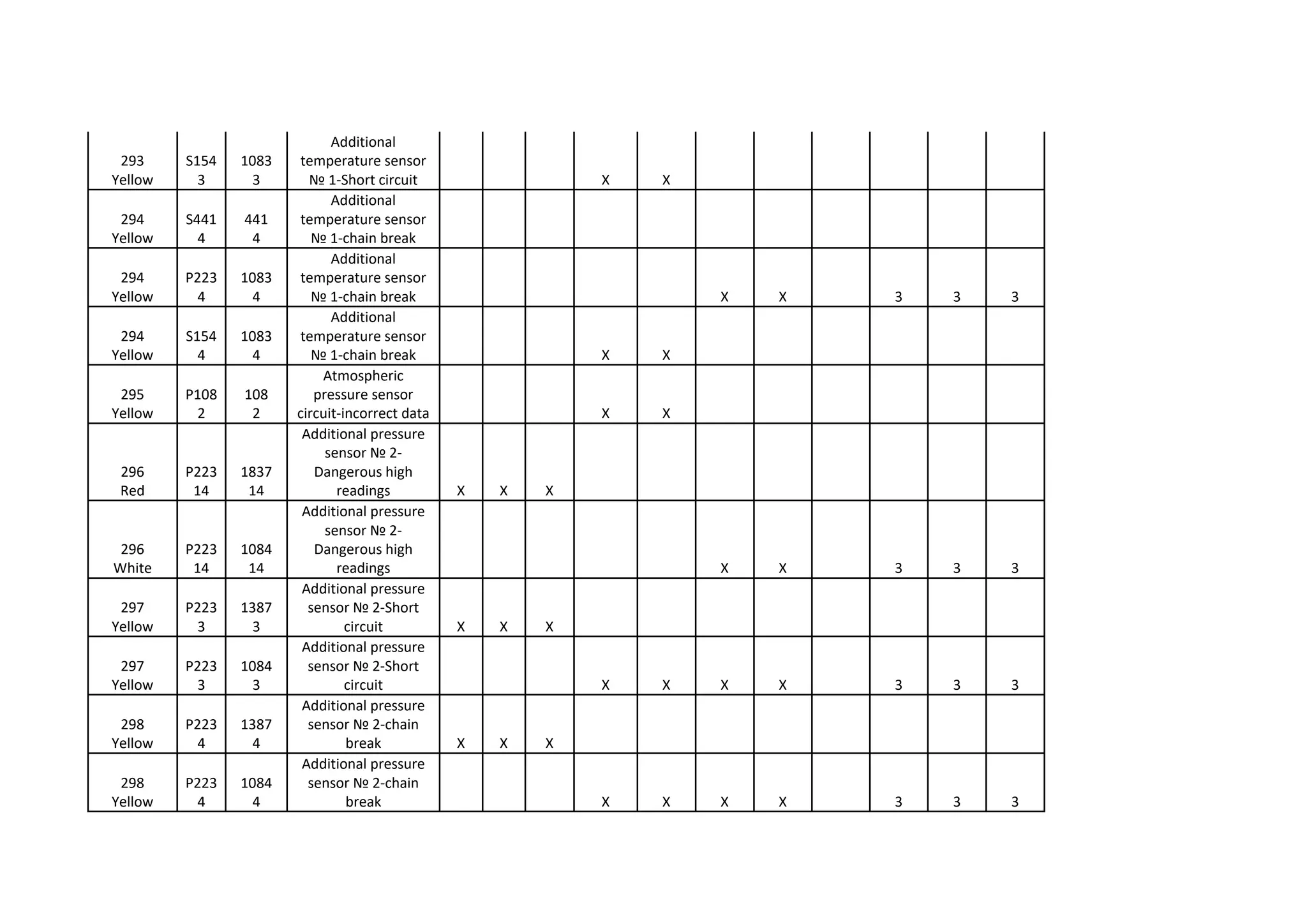
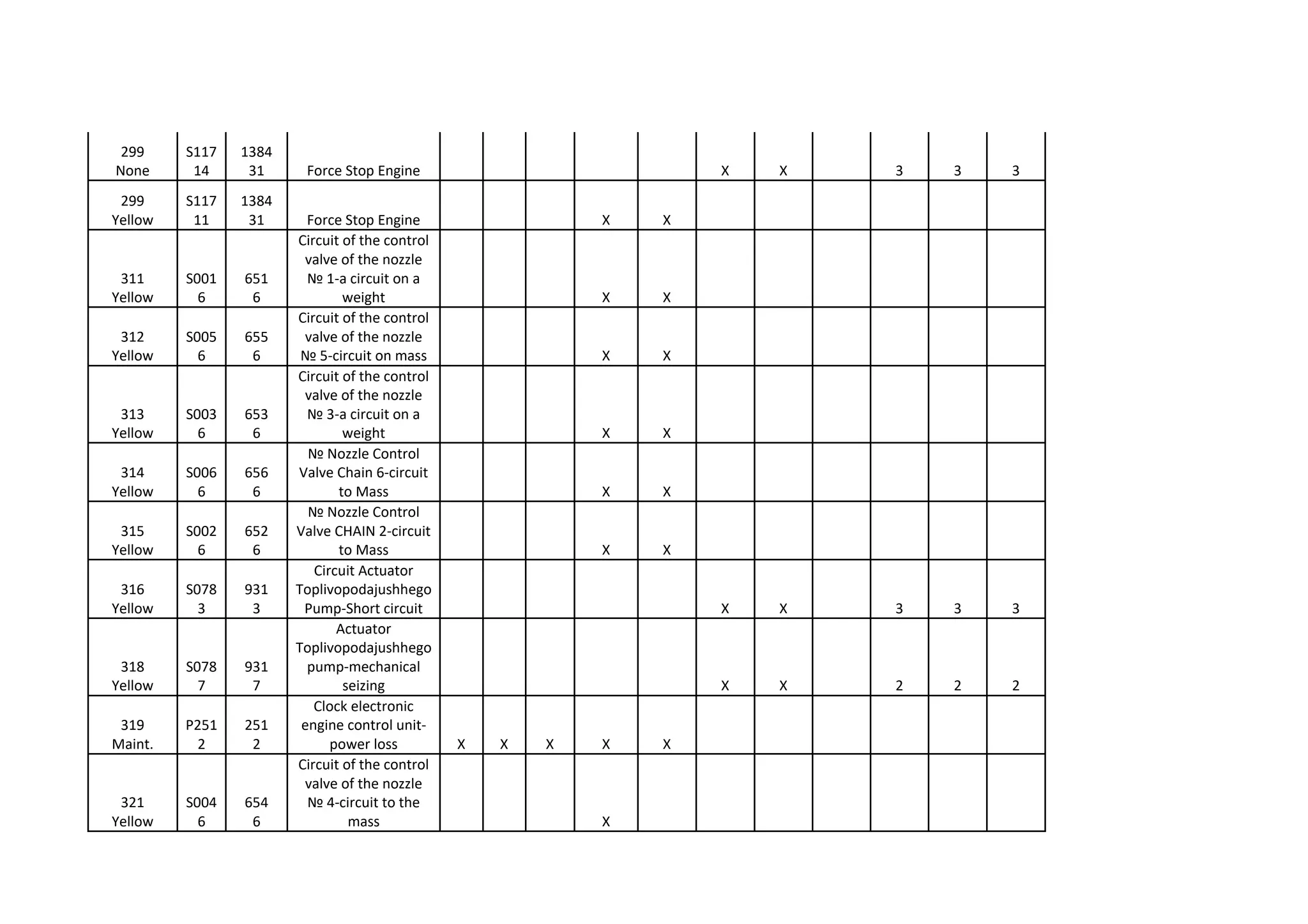
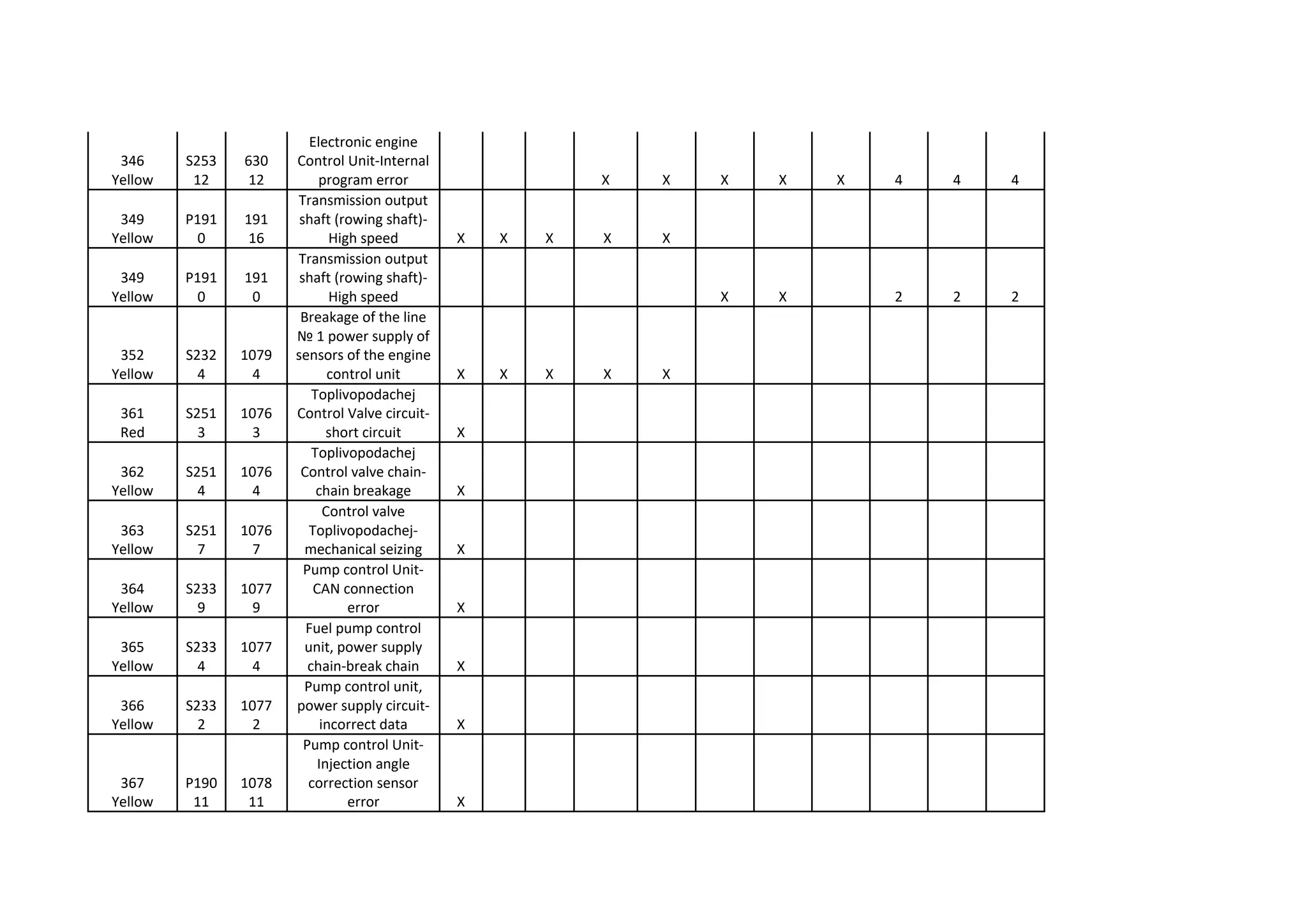
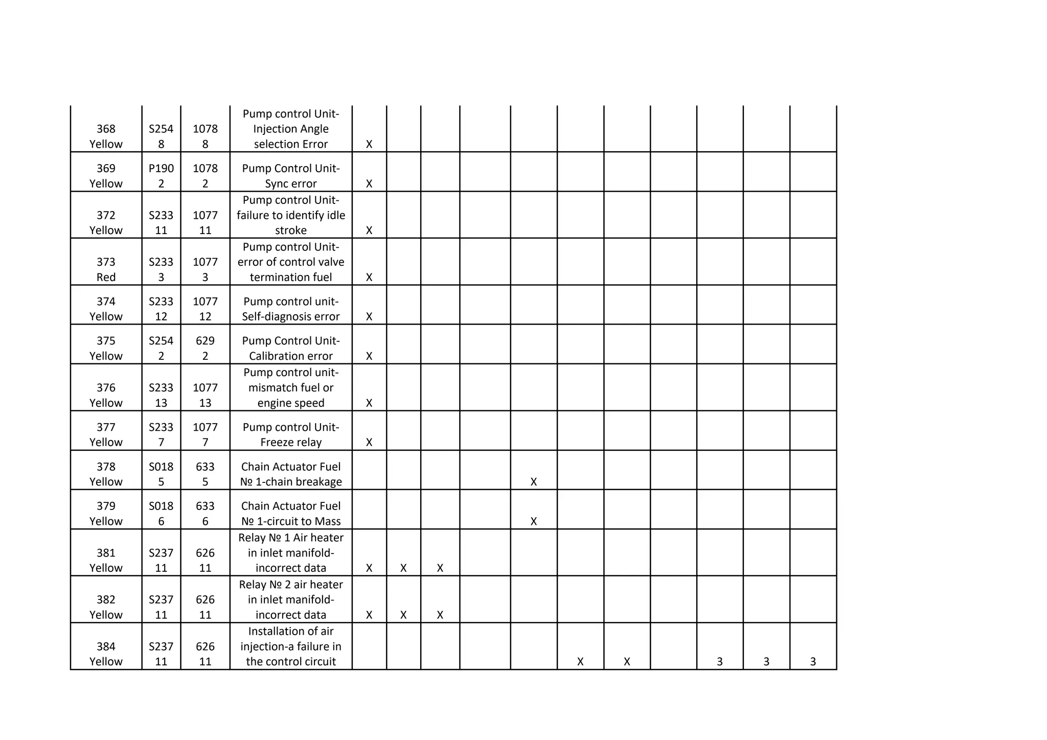
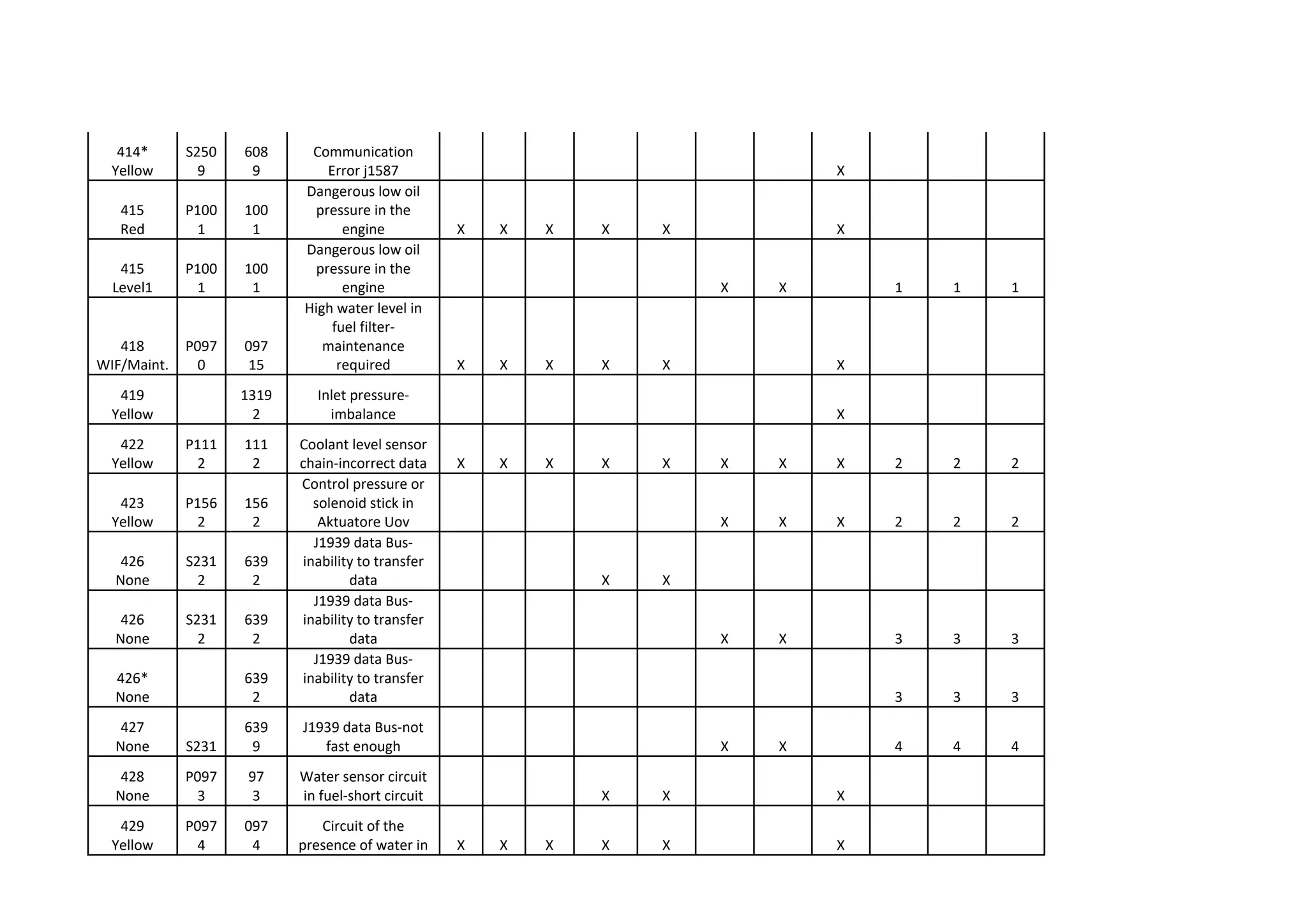
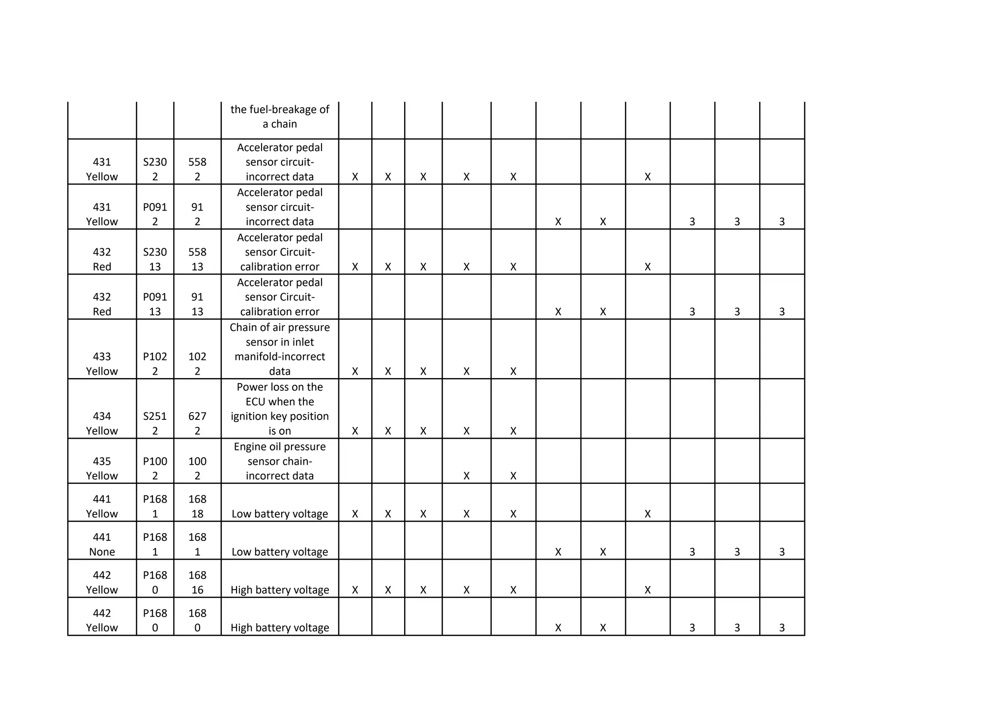
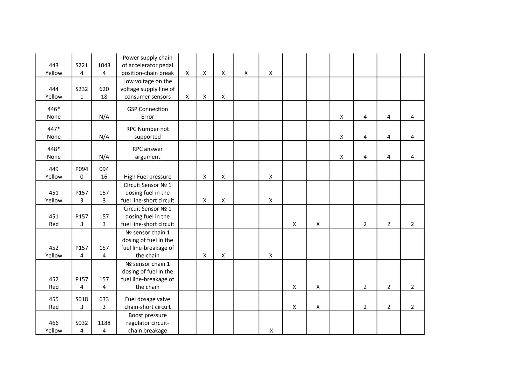
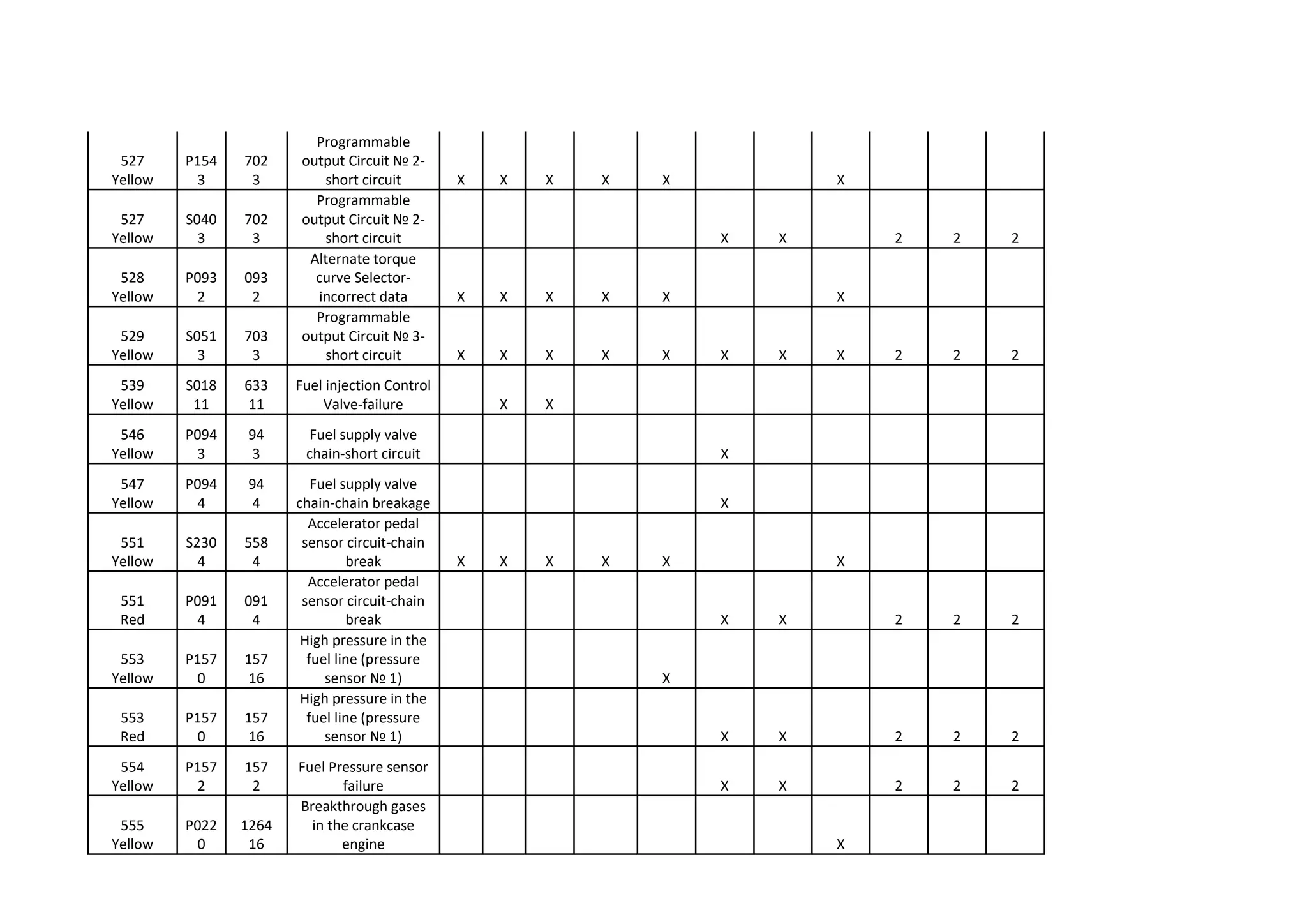
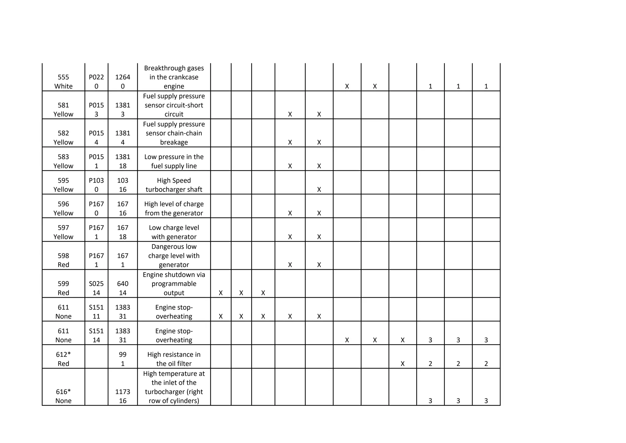
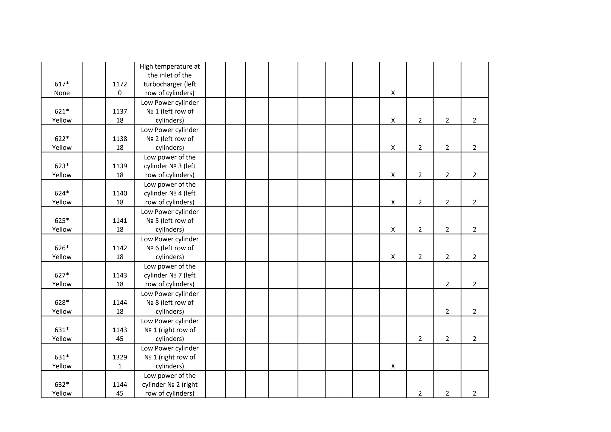
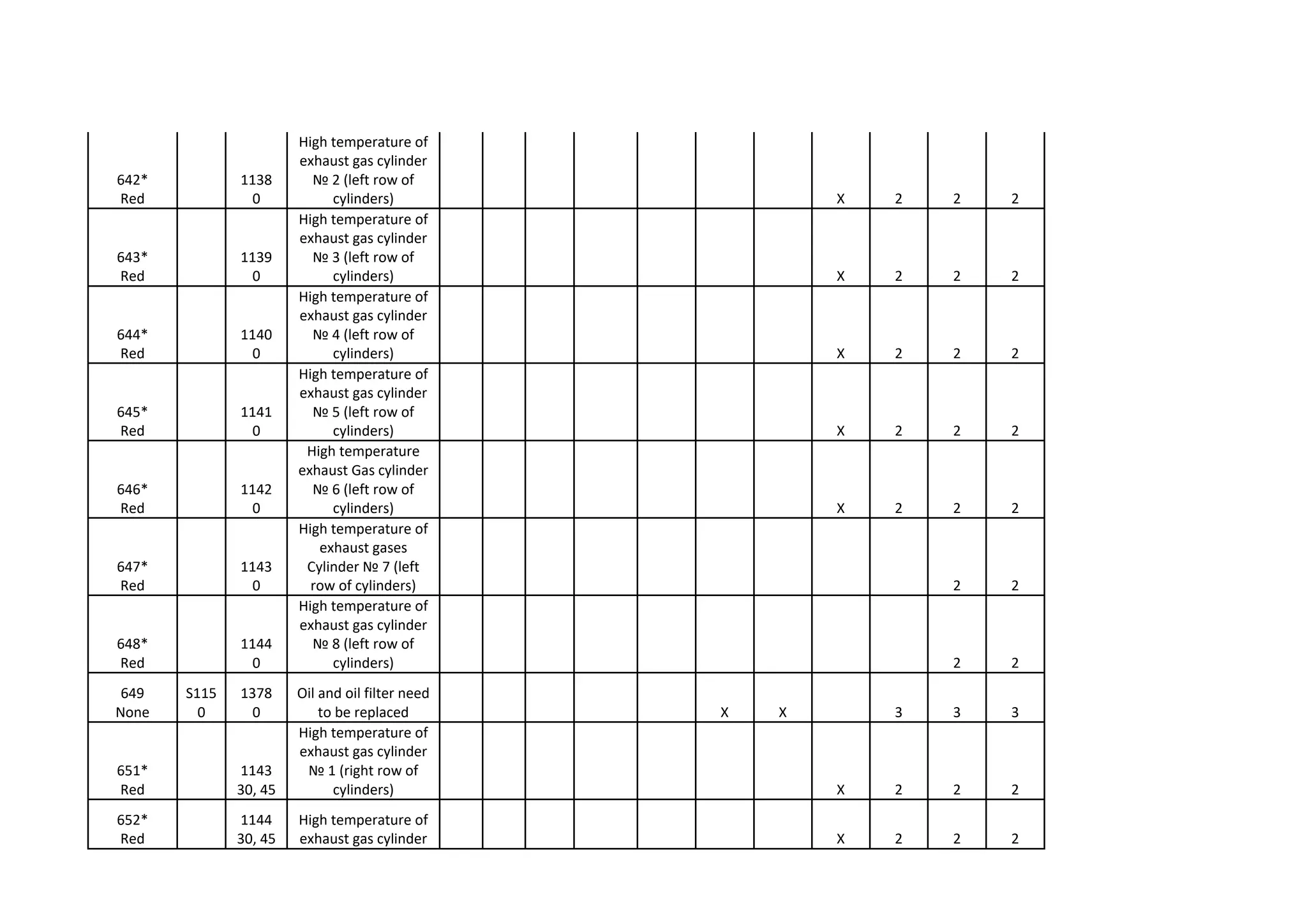
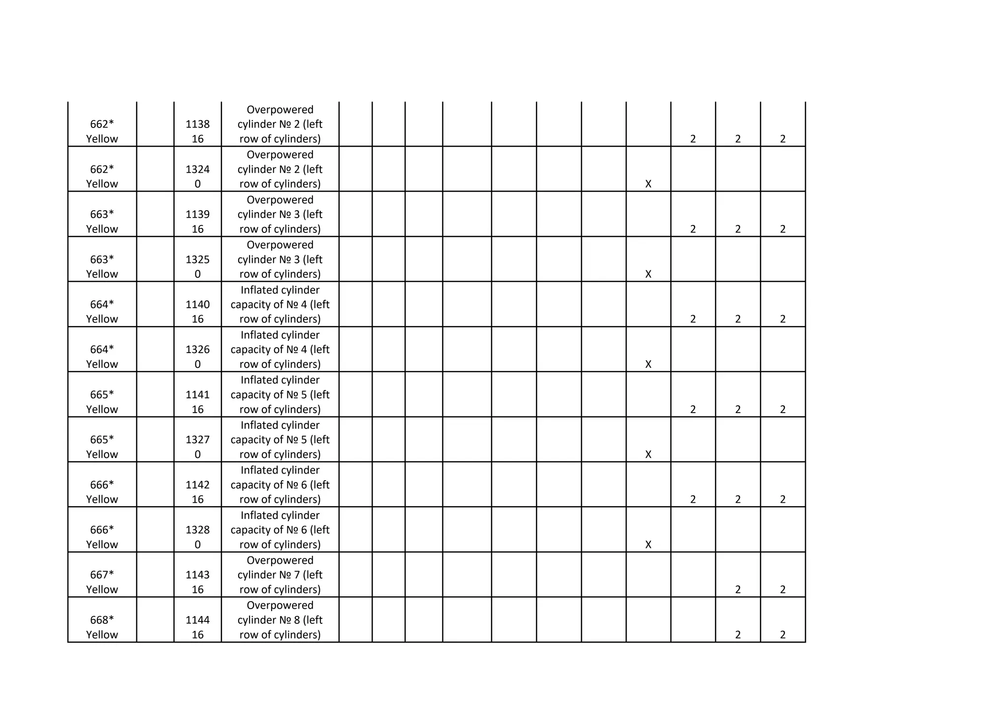
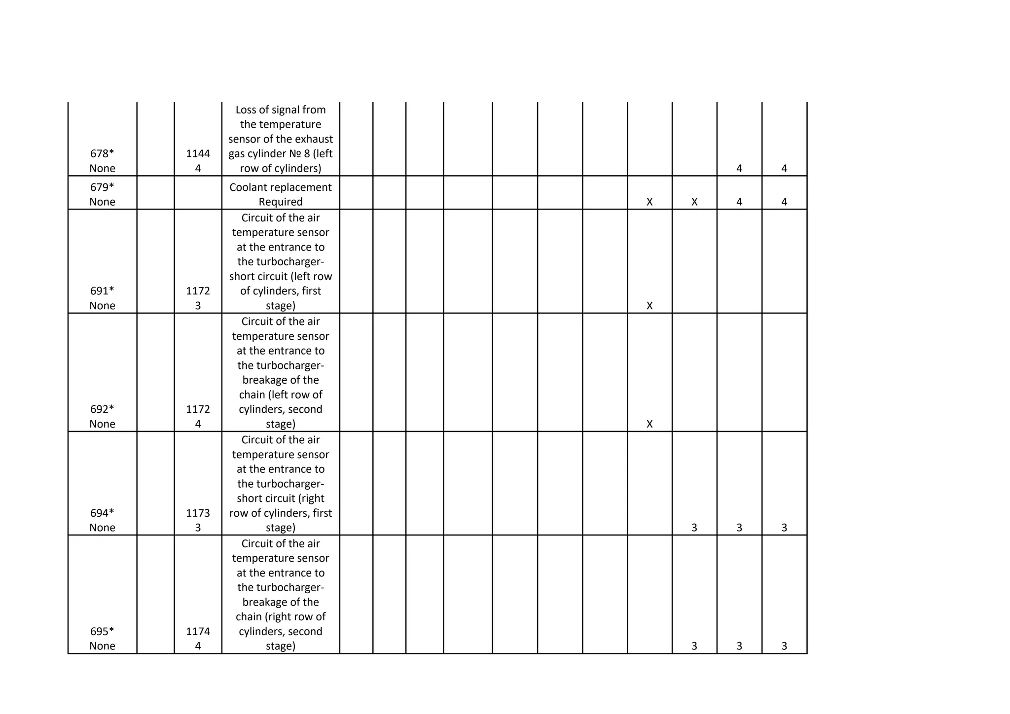
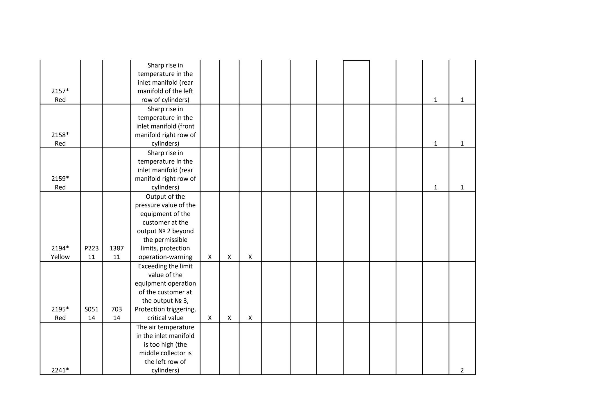
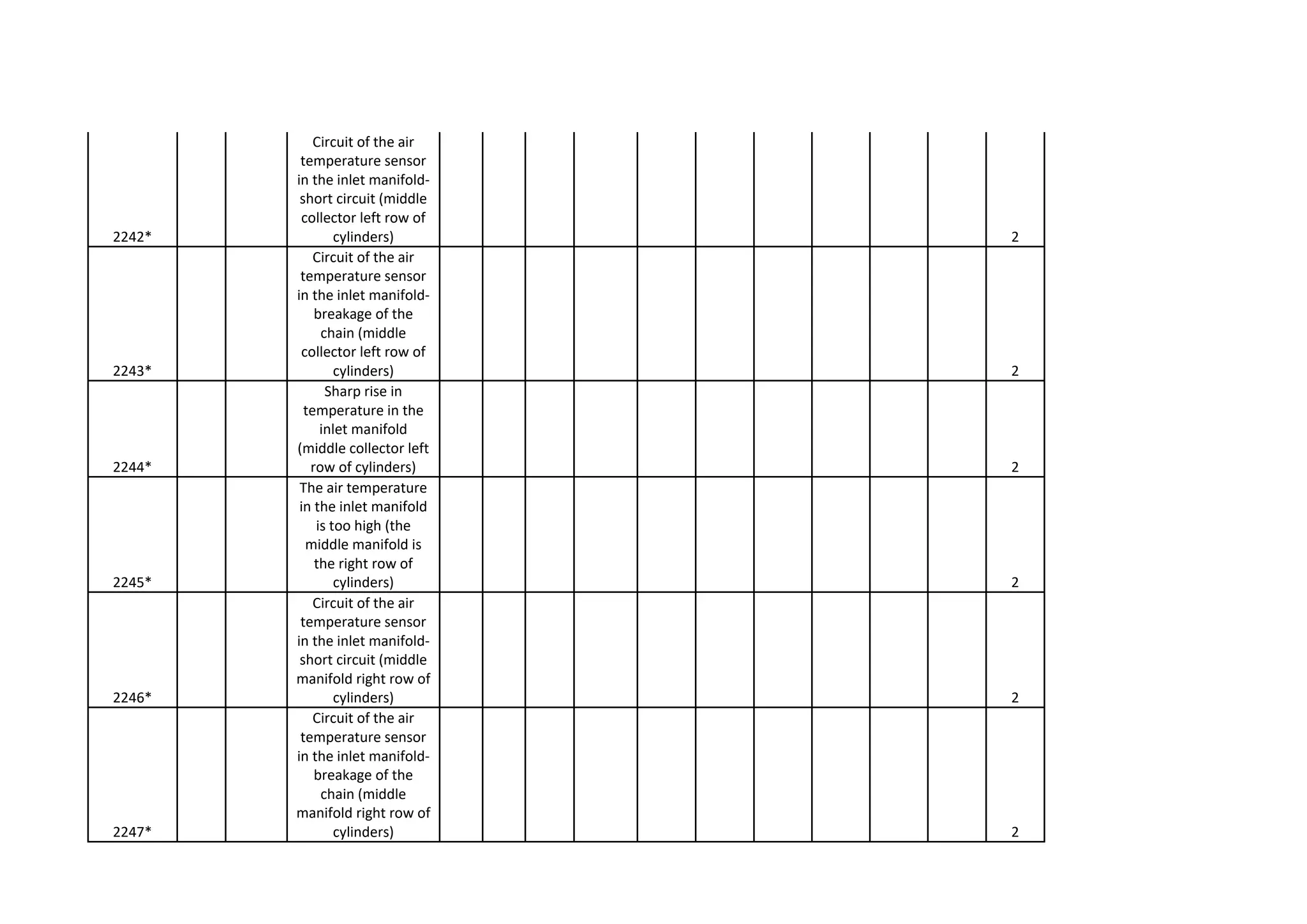
SID,
PID
FMI
SPN
FMI Description QSB QSC QSL9 QSM11 QSX15 QSK19 QSK23 QST30
HHP-level
QSK45 QSK60 QSK78
111
Red
S254
12
629
12
Engine control Unit-
critical internal error X X X X X X X X 3 3 3
112
Red
S020
7
635
7
The injection syncer
does not respond to
the commands of the
control unit X X 2 2 2
113
Yellow
S020
3
635
3
Injection timing
chain-short circuit X X X 2 2 2
114
Yellow
S020
4
635
4
Injection
synchronisation
chain-chain break X
115
Red
P190
2
190
2
Circuit of the speed
sensor and the
position of the
crankshaft-no two
signals from the
sensor X X X X X X X X 2 2 2
116
Red
P156
3
156
3
Circuit of the
pressure sensor in
the highway control
the angle of fuel
injection-short circuit X X X X 2 2 2
117
Red
P156
4
156
4
Circuit of the
pressure sensor in
the line of control of
the fuel injection
lead angle-chain
breakage X X X X 2 2 2
118
Yellow
P135
3
135
3
Circuit of the fuel
pressure sensor in
the fuel pump-short
circuit X X X X 3 3 3
119
Yellow
P135
4
135
4
Circuit of the fuel
pressure sensor in
the fuel pump-
breakage of a chain X X X X 3 3 3
121
Yellow
P190
10
190
10
Circuit of the speed
sensor and the
position of the
crankshaft-the
absence of one of
the two sensor
signals X X X X X X X 2 2 2
122
Yellow
P102
3
102
3
Pressure sensor in
Inlet manifold № 1-
Short circuit X X X X X X X X 2 2 2
123
Yellow
P102
4
102
4
Pressure sensor in
the inlet manifold №
1-chain breakage X X X X X X X X 2 2 2
124*
Yellow
102
16
High pressure in inlet
manifold (left row of
cylinders) X 3 3 3
125*
None
102
18
Low pressure in inlet
manifold (left row of
cylinders) X 3 3 3
126*
Yellow
1129
16
High pressure in inlet
manifold (right row
of cylinders) X 3 3 3
127*
None
1129
18
Low pressure in inlet
manifold (right row
of cylinders) X 3 3 3
128*
None
1129
3
Pressure sensor in
Inlet manifold (right
row of cylinders)-
Short circuit X 3 3 3
129*
None
1129
4
Pressure sensor in
Inlet manifold (right
row of cylinders)-
chain breakage X 3 3 3
131
Red
P091
3
091
3
Accelerator pedal
position sensor
circuit-short circuit X X X X X X X X 2 2 2
132
Red
P091
4
091
4
Accelerator pedal
position sensor
chain-chain breakage X X X X X X X X 2 2 2
133
Red
P029
3
974
3
Remote pedal
position sensor chain
Accelerator-Short
Circuit X X X X X X
133
Red
P029
3
29
3
Sensor Circuit of the
remote accelerator
pedal-short circuit X X 2 2 2
134
Red
P029
4
974
4
Circuit of the
position sensor of
the remote
accelerator pedal-
chain breakage X X X X X X
134
Red
P029
4
29
4
Circuit of the
position sensor of
the remote
accelerator pedal-
chain breakage X X 2 2 2
135
Yellow
P100
3
100
3
Engine oil pressure
sensor circuit-short
circuit X X X X X X X X 2 2 2
136*
None
1028
3
Prelube System oil
pressure sensor
circuit-short circuit X 3 3 3
137*
None
1028
4
Prelube System oil
pressure sensor
chain-chain breakage X 3 3 3
141
Yellow
P100
4
100
4
Chain of the oil
pressure sensor in
the engine-chain
breakage X X X X X X X X 2 2 2
143
Yellow
P100
1
100
18
Low oil pressure in
the engine X X X X X X
143
White
P100
1
100
1
Low oil pressure in
the engine X X 1 1 1
144
Yellow
P110
3
110
3
Coolant temperature
sensor circuit-short
circuit X X X X X X X X 2 2 2
145
Yellow
P110
4
110
4
Coolant temperature
sensor chain-chain
break X X X X X X X X 2 2 2
146
Yellow
P110
0
110
16
High coolant
temperature X X X
147
Red
P091
8
091
8
Accelerator pedal
position sensor
circuit-low frequency X X X X X X X X 2 2 2
148
Red
P091
8
091
8
Accelerator pedal
position sensor
chain-high frequency X X X X X X X X 2 2 2
151
Red
P110
0
110
0
Dangerously high
coolant temperature X X X X X X
151
White
P110
0
110
0
Dangerously high
coolant temperature X X 1 1 1
153
Yellow
P105
3
105
3
№ 1 temperature
sensor circuit in inlet
manifold-short
circuit X X X X X X X X 2 2 2
154
Yellow
P105
4
105
4
№ 1 temperature
sensor chain in inlet
manifold-chain
breakage X X X X X X X X 2 2 2
155
Red
P105
0
105
0
Dangerously high air
temperature in the
inlet manifold X X X X X X
155
White
P105
0
105
0
Dangerously high air
temperature in the
inlet manifold X X 1 1 1
156*
Yellow
1131
3
Rear temperature
sensor in inlet
manifold (left row)-
Short circuit 2 2 2
157*
Yellow
1131
4
Rear temperature
sensor in inlet
manifold (left row)-
chain breakage 2 2 2
158*
White
1131
0
High air temperature
in inlet manifold
(rear sensor, left row
of cylinders) 1 1 1
159*
Yellow
1132
3
Rear temperature
sensor in inlet
manifold (PRAYJ
series)-Short circuit 2 2 2
161*
Yellow
1132
4
Front temperature
sensor in inlet
manifold (right row)-
chain breakage 2 2 2
162*
White
1132
0
High air temperature
in inlet manifold
(front sensor, right
row of cylinders) 1 1 1
163*
Yellow
1133
3
Rear temperature
sensor in inlet
manifold (right row)-
short circuit 2 2 2
164*
Yellow
1133
4
Rear temperature
sensor in inlet
manifold (right row)-
chain breakage 2 2 2
165*
White
1133
0
High air temperature
in inlet manifold
(rear sensor, right
row of cylinders) 1 1 1
166
Yellow
S024
3
733
3
№ sensor chain 1
position of the fuel
pump reiki-Short
Circuit X
172
Red
S023
6
638
6
№ sensor chain 1
position of the fuel
pump reiki-circuit to
the mass X
173
Yellow
S023
7
638
7
Mechanical jamming
of the fuel pump
Reiki X
184
Yellow
S233
2
609
2
Misuse of electronic
engine control unit X X X X
185
Yellow
S231
2
639
2
Failed to
communicate with
engine control unit X
187
Yellow
S232
4
620
4
Low voltage on the
№ Line 1 power
supply sensors of the
engine control unit X X
211
None
S216
11
1484
31
Fault codes detected
in other control units
were found.
Verification is
required. X X
211*
None
613
14
Fault codes detected
in other control units
were found.
Verification is
required. X 3 3 3
212
Yellow
P175
3
175
3
Engine oil
temperature sensor
circuit-short circuit X X X
212*
Yellow
P175
3
175
3
Engine oil
temperature sensor
circuit-short circuit 2 2 2
213
Yellow
P175
4
175
4
Circuit of the oil
temperature sensor
in the engine-chain
breakage X X X
213*
Yellow
175
4
Circuit of the oil
temperature sensor
in the engine-chain
breakage 2 2 2
214
Red
P175
0
175
0
Dangerous Vysokaâ
Temperature engine
oils X X
214*
White
175
0
Dangerous Vysokaâ
Temperature engine
oils 1 1 1
219
Maint.
P17
1
1380
17
Low oil level in the
oil tank of the
Centinel system X X
219
White
P17
1
1380
1
Low oil level in the
oil tank of the
Centinel system X X 2 2 2
221
Yellow
P108
3
108
3
Atmospheric
pressure sensor
circuit-short circuit X X X X X X X 2 2 2
222
Yellow
P108
4
108
4
Atmospheric
pressure sensor
circuit-chain
breakage X X X X X X X 2 2 2
223
Yellow
S085
4
1265
4
Oil supply valve
chain for centinel
system combustion-
chain breakage X X X X 2 2 2
225
Yellow
S086
4
1266
4
Centinel system Oil
adding valve chain-
chain break X X 2 2 2
227
Yellow
S232
3
620
3
High voltage on the
№ Line 2 power
supply sensors of the
engine control unit X X
231
Yellow
P109
3
109
3
Cooling liquid
pressure sensor
circuit-short circuit X X X 2 2 2
232
Yellow
P109
4
109
4
Cooling liquid
pressure sensor
chain-chain breakage X X X 2 2 2
233
Yellow
P109
1
109
18 Low coolant pressure X
233
White
P109
1
109
1 Low coolant pressure X X 1 1 1
234
Red
P190
0
190
0
Dangerous high
engine speed X X X X X X X X 3 3 3
235
Red
P111
1
111
1
Dangerous low
coolant level X X X X X X
235
White
P111
1
111
1
Dangerous low
coolant level X X 1 1 1
237
Yellow
S030
2
644
2
Multiengine
synchronization-
Incorrect external
speed data X X X 2 2 2
241
Yellow
P084
2
084
2
Speed sensor circuit-
incorrect data X X X X X
242
Yellow
P084
10
084
10
Speed sensor-
evidence tampering
detected X X X X X
243
Yellow
P121
4
513
4
Motor Brake № 1
Drive-Chain break X X X
245
Yellow
S033
4
647
4
Fan drive coupling
chain-chain breakage X X X X X
252
Yellow
P098
2
098
2
№ sensor chain 1 oil
level in the engine-
incorrect data 2 2 2
253
White
P098
1
098
1
№ Sensor 1 Oil level
in the engine-
dangerous low oil
level 1 1 1
254
Red
S017
4
632
4
Fuel cut-off valve
chain-chain breakage X X X
254
None
S017
4
632
4
Fuel cut-off valve
chain-chain breakage X X 2 2 2
255
Yellow
S017
3
632
3
Fuel cut-off valve
circuit-short circuit X X
259
Red
S017
7
632
7
Fuel cut-off valve-
jamming in open
position X X X X 2 2 2
261
Yellow
P174
0
174
16
High fuel
temperature X
263
Yellow
P174
3
174
3
Fuel temperature
sensor circuit-short
circuit X X X X 2 2 2
264
Yellow
P174
11
174
11
Fuel temperature
sensor circuit-
incorrect data X
265
Yellow
P174
4
174
4
Fuel temperature
sensor circuit-chain
breakage X X X X 2 2 2
268
Yellow
P094
2
94
2
Fuel pressure sensor
circuit-incorrect data X X
271
Yellow
S126
4
1347
4
№ 1 High-pressure
gas control valve
chain-chain breakage X X
272
Yellow
S126
3
1347
3
№ 1 high-pressure
monitoring valve
chain-short circuit X X
273
Yellow
S127
4
1348
4
№ 2 high-pressure
control valve chain
Fuel pressure-chain
breakage X X
274
Yellow
S127
3
1348
3
№ 2 high-pressure
monitoring valve
chain-short circuit X X
275
Yellow
S126
7
1347
7
Injection VALVE № 1
fuel pump-
mechanical seizing X X
276
Yellow
S018
3
633
3
Fuel dosage valve
Chain/Uov
regulation-Short
circuit X X
277
Yellow
S018
7
633
7
Fuel dosing
valve/UOV
regulation-
Mechanical seizing X X
278
Yellow
P073
11
1075
11
Booster pump
control circuit-short
circuit/chain
breakage X X X
279
Yellow
S018
4
633
4
Fuel dosage valve
Chain/uov
regulation-chain
breakage X X
281
Yellow
S126
7
1347
7
Control Valve № 1
High-pressure fuel-
mechanical seizing X X
282
Yellow
S127
7
1348
7
Control Valve № 2
High-pressure fuel-
mechanical seizing X X
283
Yellow
S221
3
1043
3
Power supply chain
of engine pistons-
short circuit X X X
284
Yellow
S221
4
1043
4
Power supply circuit
of the engine
pistons/position-
chain break X X X X
285
Yellow
S231
9
639
9
No response from
the device
transmitted on the
bus J1939 X X X X X
286
Yellow
S231
13
639
13
Incorrect
transmission of
J1939 data from the
device to the bus X X X X X
287
Red
P091
2
91
19
Incorrect data
transmission on the
J1939 bus from the
pedal position sensor X X X X X
288
Red
P029
2
974
19
Incorrect data
transmission on the
J1939 bus from the
position sensor of
the remote pedal X X X X X
292
White
P223
14
1083
14
Additional
temperature sensor
№ 1-Dangerous high
readings X X 3 3 3
293
Yellow
S441
3
441
3
Additional
temperature sensor
№ 1-Short circuit
293
Yellow
S223
3
1083
3
Additional
temperature sensor
№ 1-Short circuit X X 3 3 3
293
Yellow
S154
3
1083
3
Additional
temperature sensor
№ 1-Short circuit X X
294
Yellow
S441
4
441
4
Additional
temperature sensor
№ 1-chain break
294
Yellow
P223
4
1083
4
Additional
temperature sensor
№ 1-chain break X X 3 3 3
294
Yellow
S154
4
1083
4
Additional
temperature sensor
№ 1-chain break X X
295
Yellow
P108
2
108
2
Atmospheric
pressure sensor
circuit-incorrect data X X
296
Red
P223
14
1837
14
Additional pressure
sensor № 2-
Dangerous high
readings X X X
296
White
P223
14
1084
14
Additional pressure
sensor № 2-
Dangerous high
readings X X 3 3 3
297
Yellow
P223
3
1387
3
Additional pressure
sensor № 2-Short
circuit X X X
297
Yellow
P223
3
1084
3
Additional pressure
sensor № 2-Short
circuit X X X X 3 3 3
298
Yellow
P223
4
1387
4
Additional pressure
sensor № 2-chain
break X X X
298
Yellow
P223
4
1084
4
Additional pressure
sensor № 2-chain
break X X X X 3 3 3
299
None
S117
14
1384
31 Force Stop Engine X X 3 3 3
299
Yellow
S117
11
1384
31 Force Stop Engine X X
311
Yellow
S001
6
651
6
Circuit of the control
valve of the nozzle
№ 1-a circuit on a
weight X X
312
Yellow
S005
6
655
6
Circuit of the control
valve of the nozzle
№ 5-circuit on mass X X
313
Yellow
S003
6
653
6
Circuit of the control
valve of the nozzle
№ 3-a circuit on a
weight X X
314
Yellow
S006
6
656
6
№ Nozzle Control
Valve Chain 6-circuit
to Mass X X
315
Yellow
S002
6
652
6
№ Nozzle Control
Valve CHAIN 2-circuit
to Mass X X
316
Yellow
S078
3
931
3
Circuit Actuator
Toplivopodajushhego
Pump-Short circuit X X 3 3 3
318
Yellow
S078
7
931
7
Actuator
Toplivopodajushhego
pump-mechanical
seizing X X 2 2 2
319
Maint.
P251
2
251
2
Clock electronic
engine control unit-
power loss X X X X X
321
Yellow
S004
6
654
6
Circuit of the control
valve of the nozzle
№ 4-circuit to the
mass X
322
Yellow
S001
5
651
5
Circuit of the control
valve of the nozzle
№ 1-breakage of a
chain X
323
Yellow
S005
5
655
5
Circuit of the control
valve of the nozzle
№ 5-breakage of a
chain X
324
Yellow
S003
5
653
5
Circuit of the control
valve of the nozzle
№ 3-breakage of a
chain X
325
Yellow
S006
5
656
5
№ Nozzle Control
Valve chain 6-chain
breakage X
328
Yellow
S152
7
1348
7
Injection VALVE № 2
pump-mechanical
seizing X X
329
Yellow
S233
14
1077
14
Disruption of fuel
system-fuel flow X X
331
Yellow
S002
5
652
5
№ Nozzle Control
Valve CHAIN 2-chain
breakage X
332
Yellow
S004
5
654
5
Circuit of the control
valve of the nozzle
№ 4-breakage of a
chain X
341
Yellow
S253
2
630
2
Electronic engine
control unit-data loss X X
342
Red
S253
13
630
13
Electronic engine
control Unit-
Calibration error X
343
Yellow
S254
12
629
12
Electronic engine
control Unit-Internal
device error X X X X X 4 4 4
346
Yellow
S253
12
630
12
Electronic engine
Control Unit-Internal
program error X X X X X 4 4 4
349
Yellow
P191
0
191
16
Transmission output
shaft (rowing shaft)-
High speed X X X X X
349
Yellow
P191
0
191
0
Transmission output
shaft (rowing shaft)-
High speed X X 2 2 2
352
Yellow
S232
4
1079
4
Breakage of the line
№ 1 power supply of
sensors of the engine
control unit X X X X X
361
Red
S251
3
1076
3
Toplivopodachej
Control Valve circuit-
short circuit X
362
Yellow
S251
4
1076
4
Toplivopodachej
Control valve chain-
chain breakage X
363
Yellow
S251
7
1076
7
Control valve
Toplivopodachej-
mechanical seizing X
364
Yellow
S233
9
1077
9
Pump control Unit-
CAN connection
error X
365
Yellow
S233
4
1077
4
Fuel pump control
unit, power supply
chain-break chain X
366
Yellow
S233
2
1077
2
Pump control unit,
power supply circuit-
incorrect data X
367
Yellow
P190
11
1078
11
Pump control Unit-
Injection angle
correction sensor
error X
368
Yellow
S254
8
1078
8
Pump control Unit-
Injection Angle
selection Error X
369
Yellow
P190
2
1078
2
Pump Control Unit-
Sync error X
372
Yellow
S233
11
1077
11
Pump control Unit-
failure to identify idle
stroke X
373
Red
S233
3
1077
3
Pump control Unit-
error of control valve
termination fuel X
374
Yellow
S233
12
1077
12
Pump control unit-
Self-diagnosis error X
375
Yellow
S254
2
629
2
Pump Control Unit-
Calibration error X
376
Yellow
S233
13
1077
13
Pump control unit-
mismatch fuel or
engine speed X
377
Yellow
S233
7
1077
7
Pump control Unit-
Freeze relay X
378
Yellow
S018
5
633
5
Chain Actuator Fuel
№ 1-chain breakage X
379
Yellow
S018
6
633
6
Chain Actuator Fuel
№ 1-circuit to Mass X
381
Yellow
S237
11
626
11
Relay № 1 Air heater
in inlet manifold-
incorrect data X X X
382
Yellow
S237
11
626
11
Relay № 2 air heater
in inlet manifold-
incorrect data X X X
384
Yellow
S237
11
626
11
Installation of air
injection-a failure in
the control circuit X X 3 3 3
385
Yellow
S232
11
620
3
Consumer sensor
power supply circuit-
short circuit X X X
386
Yellow
S232
3
1079
3
Circuit № 1 Power
sensor engine-short
circuit X X X X X
387
Yellow
S221
3
1043
3
Accelerator pedal
position Sensor
power supply circuit-
short circuit X X X X X
389
Yellow
S033
11
647
11
Fan Clutch chain
failure X X X
391
Yellow
S017
11
632
11
Failure in the power
supply circuit of the
shutdown valve fuel X X X
391
Yellow
S017
11
632
11
Failure in the power
supply circuit of the
shutdown valve fuel X
394
Yellow
S020
5
635
5
Chain actuator angle
of injection № 1-
chain break X
395
Yellow
S020
6
635
6
Chain actuator angle
of injection № 1-
circuit to Mass X
396
Yellow
S083
5
1244
5
Chain Actuator Fuel
№ 2-chain breakage X
397
Yellow
S083
6
1244
6
Chain Actuator Fuel
№ 2-circuit on the
mass X
398
Yellow
S084
5
1245
5
Chain actuator angle
of injection № 2-
chain break X
399
Yellow
S084
6
1245
6
№ 2-Circuit actuator
angle Chain X
414*
Yellow
S250
9
608
9
Communication
Error j1587 X
415
Red
P100
1
100
1
Dangerous low oil
pressure in the
engine X X X X X X
415
Level1
P100
1
100
1
Dangerous low oil
pressure in the
engine X X 1 1 1
418
WIF/Maint.
P097
0
097
15
High water level in
fuel filter-
maintenance
required X X X X X X
419
Yellow
1319
2
Inlet pressure-
imbalance X
422
Yellow
P111
2
111
2
Coolant level sensor
chain-incorrect data X X X X X X X X 2 2 2
423
Yellow
P156
2
156
2
Control pressure or
solenoid stick in
Aktuatore Uov X X X 2 2 2
426
None
S231
2
639
2
J1939 data Bus-
inability to transfer
data X X
426
None
S231
2
639
2
J1939 data Bus-
inability to transfer
data X X 3 3 3
426*
None
639
2
J1939 data Bus-
inability to transfer
data 3 3 3
427
None S231
639
9
J1939 data Bus-not
fast enough X X 4 4 4
428
None
P097
3
97
3
Water sensor circuit
in fuel-short circuit X X X
429
Yellow
P097
4
097
4
Circuit of the
presence of water in X X X X X X
the fuel-breakage of
a chain
431
Yellow
S230
2
558
2
Accelerator pedal
sensor circuit-
incorrect data X X X X X X
431
Yellow
P091
2
91
2
Accelerator pedal
sensor circuit-
incorrect data X X 3 3 3
432
Red
S230
13
558
13
Accelerator pedal
sensor Circuit-
calibration error X X X X X X
432
Red
P091
13
91
13
Accelerator pedal
sensor Circuit-
calibration error X X 3 3 3
433
Yellow
P102
2
102
2
Chain of air pressure
sensor in inlet
manifold-incorrect
data X X X X X
434
Yellow
S251
2
627
2
Power loss on the
ECU when the
ignition key position
is on X X X X X
435
Yellow
P100
2
100
2
Engine oil pressure
sensor chain-
incorrect data X X
441
Yellow
P168
1
168
18 Low battery voltage X X X X X X
441
None
P168
1
168
1 Low battery voltage X X 3 3 3
442
Yellow
P168
0
168
16 High battery voltage X X X X X X
442
Yellow
P168
0
168
0 High battery voltage X X 3 3 3
443
Yellow
S221
4
1043
4
Power supply chain
of accelerator pedal
position-chain break X X X X X
444
Yellow
S232
1
620
18
Low voltage on the
voltage supply line of
consumer sensors X X X
446*
None N/A
GSP Connection
Error X 4 4 4
447*
None N/A
RPC Number not
supported X 4 4 4
448*
None N/A
RPC answer
argument X 4 4 4
449
Yellow
P094
0
094
16 High Fuel pressure X X X
451
Yellow
P157
3
157
3
Circuit Sensor № 1
dosing fuel in the
fuel line-short circuit X X X
451
Red
P157
3
157
3
Circuit Sensor № 1
dosing fuel in the
fuel line-short circuit X X 2 2 2
452
Yellow
P157
4
157
4
№ sensor chain 1
dosing of fuel in the
fuel line-breakage of
the chain X X X
452
Red
P157
4
157
4
№ sensor chain 1
dosing of fuel in the
fuel line-breakage of
the chain X X 2 2 2
455
Red
S018
3
633
3
Fuel dosage valve
chain-short circuit X X 2 2 2
466
Yellow
S032
4
1188
4
Boost pressure
regulator circuit-
chain breakage X
467
Yellow
S020
2
635
2
Chain actuator angle
of injection-incorrect
data X X 2 2 2
468
Yellow
S018
2
633
2
Chain actuator fuel-
incorrect data X X 2 2 2
471
Maint.
P098
1
98
1
Low oil level in the
engine-maintenance
required 1 1 1
472
Maint.
P017
2
1380
2
Low oil level in the
engine (Sensor № 2)-
Maintenance
required 3 3 3
473
Yellow
P017
2
1380
2
Low oil level in the
engine (Sensor № 2)-
Attention! 2 2 2
479*
None
1318
9
Exhaust temperature
imbalance by engine
series X
482
Yellow
P094
1
094
18
Low fuel pressure-
attention! X
483
Yellow
P129
3
1349
3
Sensor Circuit № 2
dosing of fuel in the
fuel line-short circuit X
484
Yellow
P129
4
1349
4
Sensor Circuit № 2
dosing of fuel in Fuel
line-chain breakage X
485
Yellow
P129
0
1349
16
Sensor № 2 dosing of
fuel in the fuel line-
high pressure X
486
Yellow
P129
1
1349
18
Sensor № 2 dosing of
fuel in the fuel line-
low pressure X
487
Yellow
S237
1
626
1
Air injection
installation-empty
capacity X X 3 3 3
488
Yellow
P105
0
105
16
High air temperature
in inlet manifold X X X
489
Yellow
P191
1
191
18
Transmission output
shaft (rowing shaft)-
Low speed X X X X X
489
Yellow
P191
1
191
1
Transmission output
shaft (rowing shaft)-
Low speed X X 2 2 2
493
S018
13
1076
13
Fuel correction
chain-Failed X X
496
Yellow
S221
11
1043
11
Power supply circuit
of the speed
sensor/piston engine
position-failure X
497
Yellow
S114
2
1377
2
The circuit of the
switch of activation
of Multimotor
synchronization-
incorrect data X X X X X 2 2 2
514
Red
S018
7
633
7
Fuel injection control
valve-mechanical
seizing X X 2 2 2
515
Yellow
P091
3
091
3
Circuit of the
accelerator pedal
position frequency
sensor-short circuit X X X
516
Yellow
P091
4
091
4
Circuit of the
accelerator pedal
position frequency
sensor-chain break X X X
517
Yellow
S251
12
1076
12
Fuel metering
solenoid-faulty
device X
524
Yellow
P113
2
113
2
Adjusting slope
selector Switch-
incorrect data X X X X
527
Yellow
P154
3
702
3
Programmable
output Circuit № 2-
short circuit X X X X X X
527
Yellow
S040
3
702
3
Programmable
output Circuit № 2-
short circuit X X 2 2 2
528
Yellow
P093
2
093
2
Alternate torque
curve Selector-
incorrect data X X X X X X
529
Yellow
S051
3
703
3
Programmable
output Circuit № 3-
short circuit X X X X X X X X 2 2 2
539
Yellow
S018
11
633
11
Fuel injection Control
Valve-failure X X
546
Yellow
P094
3
94
3
Fuel supply valve
chain-short circuit X
547
Yellow
P094
4
94
4
Fuel supply valve
chain-chain breakage X
551
Yellow
S230
4
558
4
Accelerator pedal
sensor circuit-chain
break X X X X X X
551
Red
P091
4
091
4
Accelerator pedal
sensor circuit-chain
break X X 2 2 2
553
Yellow
P157
0
157
16
High pressure in the
fuel line (pressure
sensor № 1) X
553
Red
P157
0
157
16
High pressure in the
fuel line (pressure
sensor № 1) X X 2 2 2
554
Yellow
P157
2
157
2
Fuel Pressure sensor
failure X X 2 2 2
555
Yellow
P022
0
1264
16
Breakthrough gases
in the crankcase
engine X
555
White
P022
0
1264
0
Breakthrough gases
in the crankcase
engine X X 1 1 1
581
Yellow
P015
3
1381
3
Fuel supply pressure
sensor circuit-short
circuit X X
582
Yellow
P015
4
1381
4
Fuel supply pressure
sensor chain-chain
breakage X X
583
Yellow
P015
1
1381
18
Low pressure in the
fuel supply line X X
595
Yellow
P103
0
103
16
High Speed
turbocharger shaft X
596
Yellow
P167
0
167
16
High level of charge
from the generator X X
597
Yellow
P167
1
167
18
Low charge level
with generator X X
598
Red
P167
1
167
1
Dangerous low
charge level with
generator X X
599
Red
S025
14
640
14
Engine shutdown via
programmable
output X X X
611
None
S151
11
1383
31
Engine stop-
overheating X X X X X
611
None
S151
14
1383
31
Engine stop-
overheating X X X 3 3 3
612*
Red
99
1
High resistance in
the oil filter X 2 2 2
616*
None
1173
16
High temperature at
the inlet of the
turbocharger (right
row of cylinders) 3 3 3
617*
None
1172
0
High temperature at
the inlet of the
turbocharger (left
row of cylinders) X
621*
Yellow
1137
18
Low Power cylinder
№ 1 (left row of
cylinders) X 2 2 2
622*
Yellow
1138
18
Low Power cylinder
№ 2 (left row of
cylinders) X 2 2 2
623*
Yellow
1139
18
Low power of the
cylinder № 3 (left
row of cylinders) X 2 2 2
624*
Yellow
1140
18
Low power of the
cylinder № 4 (left
row of cylinders) X 2 2 2
625*
Yellow
1141
18
Low Power cylinder
№ 5 (left row of
cylinders) X 2 2 2
626*
Yellow
1142
18
Low Power cylinder
№ 6 (left row of
cylinders) X 2 2 2
627*
Yellow
1143
18
Low power of the
cylinder № 7 (left
row of cylinders) 2 2
628*
Yellow
1144
18
Low Power cylinder
№ 8 (left row of
cylinders) 2 2
631*
Yellow
1143
45
Low Power cylinder
№ 1 (right row of
cylinders) 2 2 2
631*
Yellow
1329
1
Low Power cylinder
№ 1 (right row of
cylinders) X
632*
Yellow
1144
45
Low power of the
cylinder № 2 (right
row of cylinders) 2 2 2
632*
Yellow
1329
1
Low power of the
cylinder № 2 (right
row of cylinders) X
633*
Yellow
1145
45
Low power of the
cylinder № 3 (right
row of cylinders) 2 2 2
633*
Yellow
1329
1
Low power of the
cylinder № 3 (right
row of cylinders) X
634*
Yellow
1146
45
Low power of the
cylinder № 4 (right
row of cylinders) 2 2 2
634*
Yellow
1329
1
Low power of the
cylinder № 4 (right
row of cylinders) X
635*
Yellow
1147
45
Low Power cylinder
№ 5 (right row of
cylinders) 2 2 2
635*
Yellow
1329
1
Low Power cylinder
№ 5 (right row of
cylinders) X
636*
Yellow
1148
45
Low power of the
cylinder № 6 (right
row of cylinders) 2 2 2
636*
Yellow
1329
1
Low power of the
cylinder № 6 (right
row of cylinders) X
637*
Yellow
1151
18
Low power of the
cylinder № 7 (right
row of cylinders) 2 2
638*
Yellow
1152
18
Low Power cylinder
№ 8 (right row of
cylinders) 2 2
641*
Red
1137
0
High temperature of
exhaust gas cylinder
№ 1 (left row of
cylinders) X 2 2 2
642*
Red
1138
0
High temperature of
exhaust gas cylinder
№ 2 (left row of
cylinders) X 2 2 2
643*
Red
1139
0
High temperature of
exhaust gas cylinder
№ 3 (left row of
cylinders) X 2 2 2
644*
Red
1140
0
High temperature of
exhaust gas cylinder
№ 4 (left row of
cylinders) X 2 2 2
645*
Red
1141
0
High temperature of
exhaust gas cylinder
№ 5 (left row of
cylinders) X 2 2 2
646*
Red
1142
0
High temperature
exhaust Gas cylinder
№ 6 (left row of
cylinders) X 2 2 2
647*
Red
1143
0
High temperature of
exhaust gases
Cylinder № 7 (left
row of cylinders) 2 2
648*
Red
1144
0
High temperature of
exhaust gas cylinder
№ 8 (left row of
cylinders) 2 2
649
None
S115
0
1378
0
Oil and oil filter need
to be replaced X X 3 3 3
651*
Red
1143
30, 45
High temperature of
exhaust gas cylinder
№ 1 (right row of
cylinders) X 2 2 2
652*
Red
1144
30, 45
High temperature of
exhaust gas cylinder X 2 2 2
№ 2 (right row of
cylinders)
653*
Red
1145
30, 45
High temperature of
exhaust gas cylinder
№ 3 (right row of
cylinders) X 2 2 2
654*
Red
1146
30, 45
High temperature of
exhaust gas cylinder
№ 4 (right row of
cylinders) X 2 2 2
655*
Red
1147
30, 45
High temperature of
exhaust gas cylinder
№ 5 (right row of
cylinders) X 2 2 2
656*
Red
1148
30, 45
High temperature
exhaust Gas cylinder
№ 6 (right row of
cylinders) X 2 2 2
657*
Red
1150
0
High temperature of
exhaust gas cylinder
№ 7 (right row of
cylinders) 2 2
658*
Red
1151
0
High temperature of
exhaust gas cylinder
№ 8 (right row of
cylinders) 2 2
659*
None
Fuel Filter
Replacement
Required X 4 4 4
661*
Yellow
1137
16
Inflated cylinder
power № 1 (left row
of cylinders) 2 2 2
661*
Yellow
1323
0
Inflated cylinder
power № 1 (left row
of cylinders) X
662*
Yellow
1138
16
Overpowered
cylinder № 2 (left
row of cylinders) 2 2 2
662*
Yellow
1324
0
Overpowered
cylinder № 2 (left
row of cylinders) X
663*
Yellow
1139
16
Overpowered
cylinder № 3 (left
row of cylinders) 2 2 2
663*
Yellow
1325
0
Overpowered
cylinder № 3 (left
row of cylinders) X
664*
Yellow
1140
16
Inflated cylinder
capacity of № 4 (left
row of cylinders) 2 2 2
664*
Yellow
1326
0
Inflated cylinder
capacity of № 4 (left
row of cylinders) X
665*
Yellow
1141
16
Inflated cylinder
capacity of № 5 (left
row of cylinders) 2 2 2
665*
Yellow
1327
0
Inflated cylinder
capacity of № 5 (left
row of cylinders) X
666*
Yellow
1142
16
Inflated cylinder
capacity of № 6 (left
row of cylinders) 2 2 2
666*
Yellow
1328
0
Inflated cylinder
capacity of № 6 (left
row of cylinders) X
667*
Yellow
1143
16
Overpowered
cylinder № 7 (left
row of cylinders) 2 2
668*
Yellow
1144
16
Overpowered
cylinder № 8 (left
row of cylinders) 2 2
669*
None
Need to replace the
coolant filter X 4 4 4
671*
None
1137
4
Loss of signal from
the temperature
sensor of the exhaust
gas cylinder № 1 (left
row of cylinders) X 4 4 4
672*
None
1138
4
Loss of signal from
the temperature
sensor of the exhaust
gas cylinder № 2 (left
row of cylinders) X 4 4 4
673*
None
1139
4
Loss of signal from
the temperature
sensor of the exhaust
gas cylinder № 3 (left
row of cylinders) X 4 4 4
674*
None
1140
4
Loss of signal from
the temperature
sensor of the exhaust
gas cylinder № 4 (left
row of cylinders) X 4 4 4
675*
None
1141
4
Loss of signal from
the temperature
sensor of the exhaust
gas cylinder № 5 (left
row of cylinders) X 4 4 4
676*
None
1142
4
Loss of signal from
the temperature
sensor of the exhaust
gas cylinder № 6 (left
row of cylinders) X 4 4 4
677*
None
1143
4
Loss of signal from
the temperature
sensor of the exhaust
gas cylinder № 7 (left
row of cylinders) 4 4
678*
None
1144
4
Loss of signal from
the temperature
sensor of the exhaust
gas cylinder № 8 (left
row of cylinders) 4 4
679*
None
Coolant replacement
Required X X 4 4
691*
None
1172
3
Circuit of the air
temperature sensor
at the entrance to
the turbocharger-
short circuit (left row
of cylinders, first
stage) X
692*
None
1172
4
Circuit of the air
temperature sensor
at the entrance to
the turbocharger-
breakage of the
chain (left row of
cylinders, second
stage) X
694*
None
1173
3
Circuit of the air
temperature sensor
at the entrance to
the turbocharger-
short circuit (right
row of cylinders, first
stage) 3 3 3
695*
None
1174
4
Circuit of the air
temperature sensor
at the entrance to
the turbocharger-
breakage of the
chain (right row of
cylinders, second
stage) 3 3 3
711*
None
1143
(45)
1145
(60
16
High power in 1m
cylinder (right row of
cylinders) 2 2 2
711*
None
1329
0
High power in 1m
cylinder (right row of
cylinders) X
712*
None
1144
(45)
1146
(60)
16
High power in 2m
cylinder (right row of
cylinders) 2 2 2
712*
None
1330
0
High power in 2m
cylinder (right row of
cylinders) X
713*
None
1145
(45)
1147
(60)
16
High power in 3m
cylinder (right row of
cylinders) 2 2 2
713*
None
1331
0
High power in 3m
cylinder (right row of
cylinders) X
714*
None
1146
(45)
1148
(60
16
High power in the
4m cylinder (right
row of cylinders) 2 2 2
714*
Yellow
1332
0
High power in the
4m cylinder (right
row of cylinders) X
715*
Yellow
1147
(45)
1148
(60)
16
High power in 5m
cylinder (right row of
cylinders) 2 2 2
715*
Yellow
1333
0
High power in 5m
cylinder (right row of
cylinders) X
716*
None
1148
(45)
1149
(60)
16
High power in 6m
cylinder (right row of
cylinders) 2 2 2
716*
Yellow
1334
0
High power in 6m
cylinder (right row of
cylinders) X
717*
Yellow
1150
0
High power in 7m
cylinder (right row of
cylinders) 2 2
718*
Yellow
1151
0
High power in the
8m cylinder (right
row of cylinders) 2 2
719 Yellow
P022
3
1264
3
Crankcase pressure
sensor chain-short
circuit X X X 2 2 2
721*
None
1143
(30,45)
1145
(60)
4
Loss of signal from
the temperature
sensor of the exhaust
gas cylinder № 1
(right row of
cylinders) X 4 4 4
722*
None
1144
(30,45)
1146
(60)
4
Loss of signal from
the temperature
sensor of the exhaust
gas cylinder № 2 X 4 4 4
(right row of
cylinders)
723*
None
1145
(30,45)
1147
(60)
4
Loss of signal from
the temperature
sensor of the exhaust
gas cylinder № 3
(right row of
cylinders) X 4 4 4
724*
None
1146
(30,45)
1148
(60)
4
Loss of signal from
the temperature
sensor of the exhaust
gas cylinder № 4
(right row of
cylinders) X 4 4 4
725*
None
1147
(30,45)
1149
(60)
4
Loss of signal from
the temperature
sensor of the exhaust
gas cylinder № 5
(right row of
cylinders) X 4 4 4
726*
None
1148
(30,45)
1150
(60)
4
Loss of signal from
the temperature
sensor of the exhaust
gas cylinder № 6
(right row of
cylinders) X 4 4 4
727*
None
1151
4
Loss of signal from
the temperature
sensor of the exhaust
gas cylinder № 7
(right row of
cylinders) 4 4
728*
None
1152
4
Loss of signal from
the temperature 4 4
sensor of the exhaust
gas cylinder № 8
(right row of
cylinders)
729
Yellow
P022
4
1264
4
Chain of pressure
sensor of crankcase
gases-chain breakage X X X 2 2 2
747*
None
Engine parameters
fixation system-free
memory running out X 4 4 4
748*
None
System of fixation of
engine parameters-
memory is over X 3 3 3
749*
None
Engine parameters
Recording system at
the moment of error
occurrence-free
memory at the same
time X 4 4 4
753
None
S064
2
723
2 X X X 3 3 3
754*
None
Engine parameters
Recording system at
the moment of error
occurrence-free
memory is over X 3 3 3
755
Yellow
P157
7
157
7
Incorrect amount of
fuel in the nozzle in
one of the first three
cylinders. X
756*
None
Oil filters need to be
replaced. X 4 4 4
757*
None
Critical power loss.
Loss of data in the
engine control unit. X 4 4 4
758
Yellow
P129
7
1349
7
Incorrect amount of
fuel in the nozzle in
one of the cylinders
from the 4th to the
6th. X
768
Yellow
S009
11
923
11
Signal error from
external device
(variable geometry
turbocharger or
transmission) X X X
777
Yellow
P173
0
1180
0
Increased
temperature at the
entrance to the
turbine Turbocharger
№ 1-Warning X 2 2 2
779
Yellow
S051
11
703
11
Exceeding the limit
value of the
parameter of the
customer's
equipment at the
outlet № 3 X X X
783
Red
Frisky increase in
temperature in inlet
manifold (front
manifold left row of
cylinders) 1 1
951
None
P166
2
166
2
Power imbalance in
cylinders X X
1000
None
The hardware
controller has
initiated the
recording of fault
codes X
2144* 0
1153
0
High temperature of
exhaust gas cylinder
№ 9 (left row of
cylinders) 2
2145*
1154
0
High temperature of
exhaust gas cylinder
№ 9 (right row of
cylinders) 2
2146* 4
1153
4
Loss of signal from
the temperature
sensor of the
graduates gas
cylinder № 9 (right
row of cylinders) 4
2147* 4
1154
4
Loss of signal from
the temperature
sensor of the
graduates gas
cylinder № 9 (left
row of cylinders) 4
2148* 0
1340
16
High power in 9m
cylinder (left row of
cylinders) 2
2149*
1341
16
High power in 9m
cylinder (right row of
cylinders) 2
2151*
1340
18
Low power in 9m
cylinder (left row of
cylinders) 2
2152*
1341
18
Low power in 9m
cylinder (right row of
cylinders) 2
2154*
None
611
3
Oil pressure sensor
chain after oil filter-
short circuit. X 3 3 3
2155*
None
611
4
The chain of the oil
pressure sensor after
the oil filter is a
breakage of the
chain. X 3 3 3
2157*
Red
Sharp rise in
temperature in the
inlet manifold (rear
manifold of the left
row of cylinders) 1 1
2158*
Red
Sharp rise in
temperature in the
inlet manifold (front
manifold right row of
cylinders) 1 1
2159*
Red
Sharp rise in
temperature in the
inlet manifold (rear
manifold right row of
cylinders) 1 1
2194*
Yellow
P223
11
1387
11
Output of the
pressure value of the
equipment of the
customer at the
output № 2 beyond
the permissible
limits, protection
operation-warning X X X
2195*
Red
S051
14
703
14
Exceeding the limit
value of the
equipment operation
of the customer at
the output № 3,
Protection triggering,
critical value X X X
2241*
The air temperature
in the inlet manifold
is too high (the
middle collector is
the left row of
cylinders) 2
2242*
Circuit of the air
temperature sensor
in the inlet manifold-
short circuit (middle
collector left row of
cylinders) 2
2243*
Circuit of the air
temperature sensor
in the inlet manifold-
breakage of the
chain (middle
collector left row of
cylinders) 2
2244*
Sharp rise in
temperature in the
inlet manifold
(middle collector left
row of cylinders) 2
2245*
The air temperature
in the inlet manifold
is too high (the
middle manifold is
the right row of
cylinders) 2
2246*
Circuit of the air
temperature sensor
in the inlet manifold-
short circuit (middle
manifold right row of
cylinders) 2
2247*
Circuit of the air
temperature sensor
in the inlet manifold-
breakage of the
chain (middle
manifold right row of
cylinders) 2
2248*
Sharp rise in
temperature in the
inlet manifold
(middle manifold
right row of
cylinders) 2
2251*
High pressurization
pressure in the front
intermediate cooler 2
2252*
Low boost pressure
in the front
intermediate cooler 2
2253*
pressurization
pressure sensor
circuit in the front
intermediate cooler-
short circuit 2
2254*
Pressurized pressure
sensor circuit in the
front intermediate
cooler-chain
breakage 2
2255*
High pressurization
pressure in the rear
intermediate cooler 2
2256*
Low boost pressure
in the rear
intermediate cooler 2
2257*
The circuit of the
pressurization
pressure sensor in
the rear
intermediate Cooler-
Short Circuit 2
2258*
Boost pressure
sensor circuit in rear 2
intermediate cooler-
chain break
https://truckmanualshub.com/cummins-engine-fault-codes-list/

Cummins Fault Codes For QSB, QSC, QSL9, QSM11, QSX15, QSK19, QSK23, QST30, QSK45, QSK60, QSK78.pdf

  • 1.
    SID, PID FMI SPN FMI Description QSBQSC QSL9 QSM11 QSX15 QSK19 QSK23 QST30 HHP-level QSK45 QSK60 QSK78 111 Red S254 12 629 12 Engine control Unit- critical internal error X X X X X X X X 3 3 3 112 Red S020 7 635 7 The injection syncer does not respond to the commands of the control unit X X 2 2 2 113 Yellow S020 3 635 3 Injection timing chain-short circuit X X X 2 2 2 114 Yellow S020 4 635 4 Injection synchronisation chain-chain break X 115 Red P190 2 190 2 Circuit of the speed sensor and the position of the crankshaft-no two signals from the sensor X X X X X X X X 2 2 2 116 Red P156 3 156 3 Circuit of the pressure sensor in the highway control the angle of fuel injection-short circuit X X X X 2 2 2 117 Red P156 4 156 4 Circuit of the pressure sensor in the line of control of the fuel injection lead angle-chain breakage X X X X 2 2 2 118 Yellow P135 3 135 3 Circuit of the fuel pressure sensor in the fuel pump-short circuit X X X X 3 3 3
  • 2.
    119 Yellow P135 4 135 4 Circuit of thefuel pressure sensor in the fuel pump- breakage of a chain X X X X 3 3 3 121 Yellow P190 10 190 10 Circuit of the speed sensor and the position of the crankshaft-the absence of one of the two sensor signals X X X X X X X 2 2 2 122 Yellow P102 3 102 3 Pressure sensor in Inlet manifold № 1- Short circuit X X X X X X X X 2 2 2 123 Yellow P102 4 102 4 Pressure sensor in the inlet manifold № 1-chain breakage X X X X X X X X 2 2 2 124* Yellow 102 16 High pressure in inlet manifold (left row of cylinders) X 3 3 3 125* None 102 18 Low pressure in inlet manifold (left row of cylinders) X 3 3 3 126* Yellow 1129 16 High pressure in inlet manifold (right row of cylinders) X 3 3 3 127* None 1129 18 Low pressure in inlet manifold (right row of cylinders) X 3 3 3 128* None 1129 3 Pressure sensor in Inlet manifold (right row of cylinders)- Short circuit X 3 3 3 129* None 1129 4 Pressure sensor in Inlet manifold (right row of cylinders)- chain breakage X 3 3 3
  • 3.
    131 Red P091 3 091 3 Accelerator pedal position sensor circuit-shortcircuit X X X X X X X X 2 2 2 132 Red P091 4 091 4 Accelerator pedal position sensor chain-chain breakage X X X X X X X X 2 2 2 133 Red P029 3 974 3 Remote pedal position sensor chain Accelerator-Short Circuit X X X X X X 133 Red P029 3 29 3 Sensor Circuit of the remote accelerator pedal-short circuit X X 2 2 2 134 Red P029 4 974 4 Circuit of the position sensor of the remote accelerator pedal- chain breakage X X X X X X 134 Red P029 4 29 4 Circuit of the position sensor of the remote accelerator pedal- chain breakage X X 2 2 2 135 Yellow P100 3 100 3 Engine oil pressure sensor circuit-short circuit X X X X X X X X 2 2 2 136* None 1028 3 Prelube System oil pressure sensor circuit-short circuit X 3 3 3 137* None 1028 4 Prelube System oil pressure sensor chain-chain breakage X 3 3 3 141 Yellow P100 4 100 4 Chain of the oil pressure sensor in the engine-chain breakage X X X X X X X X 2 2 2
  • 4.
    143 Yellow P100 1 100 18 Low oil pressurein the engine X X X X X X 143 White P100 1 100 1 Low oil pressure in the engine X X 1 1 1 144 Yellow P110 3 110 3 Coolant temperature sensor circuit-short circuit X X X X X X X X 2 2 2 145 Yellow P110 4 110 4 Coolant temperature sensor chain-chain break X X X X X X X X 2 2 2 146 Yellow P110 0 110 16 High coolant temperature X X X 147 Red P091 8 091 8 Accelerator pedal position sensor circuit-low frequency X X X X X X X X 2 2 2 148 Red P091 8 091 8 Accelerator pedal position sensor chain-high frequency X X X X X X X X 2 2 2 151 Red P110 0 110 0 Dangerously high coolant temperature X X X X X X 151 White P110 0 110 0 Dangerously high coolant temperature X X 1 1 1 153 Yellow P105 3 105 3 № 1 temperature sensor circuit in inlet manifold-short circuit X X X X X X X X 2 2 2 154 Yellow P105 4 105 4 № 1 temperature sensor chain in inlet manifold-chain breakage X X X X X X X X 2 2 2 155 Red P105 0 105 0 Dangerously high air temperature in the inlet manifold X X X X X X
  • 5.
    155 White P105 0 105 0 Dangerously high air temperaturein the inlet manifold X X 1 1 1 156* Yellow 1131 3 Rear temperature sensor in inlet manifold (left row)- Short circuit 2 2 2 157* Yellow 1131 4 Rear temperature sensor in inlet manifold (left row)- chain breakage 2 2 2 158* White 1131 0 High air temperature in inlet manifold (rear sensor, left row of cylinders) 1 1 1 159* Yellow 1132 3 Rear temperature sensor in inlet manifold (PRAYJ series)-Short circuit 2 2 2 161* Yellow 1132 4 Front temperature sensor in inlet manifold (right row)- chain breakage 2 2 2 162* White 1132 0 High air temperature in inlet manifold (front sensor, right row of cylinders) 1 1 1 163* Yellow 1133 3 Rear temperature sensor in inlet manifold (right row)- short circuit 2 2 2 164* Yellow 1133 4 Rear temperature sensor in inlet manifold (right row)- chain breakage 2 2 2
  • 6.
    165* White 1133 0 High air temperature ininlet manifold (rear sensor, right row of cylinders) 1 1 1 166 Yellow S024 3 733 3 № sensor chain 1 position of the fuel pump reiki-Short Circuit X 172 Red S023 6 638 6 № sensor chain 1 position of the fuel pump reiki-circuit to the mass X 173 Yellow S023 7 638 7 Mechanical jamming of the fuel pump Reiki X 184 Yellow S233 2 609 2 Misuse of electronic engine control unit X X X X 185 Yellow S231 2 639 2 Failed to communicate with engine control unit X 187 Yellow S232 4 620 4 Low voltage on the № Line 1 power supply sensors of the engine control unit X X 211 None S216 11 1484 31 Fault codes detected in other control units were found. Verification is required. X X 211* None 613 14 Fault codes detected in other control units were found. Verification is required. X 3 3 3
  • 7.
    212 Yellow P175 3 175 3 Engine oil temperature sensor circuit-shortcircuit X X X 212* Yellow P175 3 175 3 Engine oil temperature sensor circuit-short circuit 2 2 2 213 Yellow P175 4 175 4 Circuit of the oil temperature sensor in the engine-chain breakage X X X 213* Yellow 175 4 Circuit of the oil temperature sensor in the engine-chain breakage 2 2 2 214 Red P175 0 175 0 Dangerous Vysokaâ Temperature engine oils X X 214* White 175 0 Dangerous Vysokaâ Temperature engine oils 1 1 1 219 Maint. P17 1 1380 17 Low oil level in the oil tank of the Centinel system X X 219 White P17 1 1380 1 Low oil level in the oil tank of the Centinel system X X 2 2 2 221 Yellow P108 3 108 3 Atmospheric pressure sensor circuit-short circuit X X X X X X X 2 2 2 222 Yellow P108 4 108 4 Atmospheric pressure sensor circuit-chain breakage X X X X X X X 2 2 2 223 Yellow S085 4 1265 4 Oil supply valve chain for centinel system combustion- chain breakage X X X X 2 2 2
  • 8.
    225 Yellow S086 4 1266 4 Centinel system Oil addingvalve chain- chain break X X 2 2 2 227 Yellow S232 3 620 3 High voltage on the № Line 2 power supply sensors of the engine control unit X X 231 Yellow P109 3 109 3 Cooling liquid pressure sensor circuit-short circuit X X X 2 2 2 232 Yellow P109 4 109 4 Cooling liquid pressure sensor chain-chain breakage X X X 2 2 2 233 Yellow P109 1 109 18 Low coolant pressure X 233 White P109 1 109 1 Low coolant pressure X X 1 1 1 234 Red P190 0 190 0 Dangerous high engine speed X X X X X X X X 3 3 3 235 Red P111 1 111 1 Dangerous low coolant level X X X X X X 235 White P111 1 111 1 Dangerous low coolant level X X 1 1 1 237 Yellow S030 2 644 2 Multiengine synchronization- Incorrect external speed data X X X 2 2 2 241 Yellow P084 2 084 2 Speed sensor circuit- incorrect data X X X X X 242 Yellow P084 10 084 10 Speed sensor- evidence tampering detected X X X X X
  • 9.
    243 Yellow P121 4 513 4 Motor Brake №1 Drive-Chain break X X X 245 Yellow S033 4 647 4 Fan drive coupling chain-chain breakage X X X X X 252 Yellow P098 2 098 2 № sensor chain 1 oil level in the engine- incorrect data 2 2 2 253 White P098 1 098 1 № Sensor 1 Oil level in the engine- dangerous low oil level 1 1 1 254 Red S017 4 632 4 Fuel cut-off valve chain-chain breakage X X X 254 None S017 4 632 4 Fuel cut-off valve chain-chain breakage X X 2 2 2 255 Yellow S017 3 632 3 Fuel cut-off valve circuit-short circuit X X 259 Red S017 7 632 7 Fuel cut-off valve- jamming in open position X X X X 2 2 2 261 Yellow P174 0 174 16 High fuel temperature X 263 Yellow P174 3 174 3 Fuel temperature sensor circuit-short circuit X X X X 2 2 2 264 Yellow P174 11 174 11 Fuel temperature sensor circuit- incorrect data X 265 Yellow P174 4 174 4 Fuel temperature sensor circuit-chain breakage X X X X 2 2 2 268 Yellow P094 2 94 2 Fuel pressure sensor circuit-incorrect data X X
  • 10.
    271 Yellow S126 4 1347 4 № 1 High-pressure gascontrol valve chain-chain breakage X X 272 Yellow S126 3 1347 3 № 1 high-pressure monitoring valve chain-short circuit X X 273 Yellow S127 4 1348 4 № 2 high-pressure control valve chain Fuel pressure-chain breakage X X 274 Yellow S127 3 1348 3 № 2 high-pressure monitoring valve chain-short circuit X X 275 Yellow S126 7 1347 7 Injection VALVE № 1 fuel pump- mechanical seizing X X 276 Yellow S018 3 633 3 Fuel dosage valve Chain/Uov regulation-Short circuit X X 277 Yellow S018 7 633 7 Fuel dosing valve/UOV regulation- Mechanical seizing X X 278 Yellow P073 11 1075 11 Booster pump control circuit-short circuit/chain breakage X X X 279 Yellow S018 4 633 4 Fuel dosage valve Chain/uov regulation-chain breakage X X 281 Yellow S126 7 1347 7 Control Valve № 1 High-pressure fuel- mechanical seizing X X
  • 11.
    282 Yellow S127 7 1348 7 Control Valve №2 High-pressure fuel- mechanical seizing X X 283 Yellow S221 3 1043 3 Power supply chain of engine pistons- short circuit X X X 284 Yellow S221 4 1043 4 Power supply circuit of the engine pistons/position- chain break X X X X 285 Yellow S231 9 639 9 No response from the device transmitted on the bus J1939 X X X X X 286 Yellow S231 13 639 13 Incorrect transmission of J1939 data from the device to the bus X X X X X 287 Red P091 2 91 19 Incorrect data transmission on the J1939 bus from the pedal position sensor X X X X X 288 Red P029 2 974 19 Incorrect data transmission on the J1939 bus from the position sensor of the remote pedal X X X X X 292 White P223 14 1083 14 Additional temperature sensor № 1-Dangerous high readings X X 3 3 3 293 Yellow S441 3 441 3 Additional temperature sensor № 1-Short circuit 293 Yellow S223 3 1083 3 Additional temperature sensor № 1-Short circuit X X 3 3 3
  • 12.
    293 Yellow S154 3 1083 3 Additional temperature sensor № 1-Shortcircuit X X 294 Yellow S441 4 441 4 Additional temperature sensor № 1-chain break 294 Yellow P223 4 1083 4 Additional temperature sensor № 1-chain break X X 3 3 3 294 Yellow S154 4 1083 4 Additional temperature sensor № 1-chain break X X 295 Yellow P108 2 108 2 Atmospheric pressure sensor circuit-incorrect data X X 296 Red P223 14 1837 14 Additional pressure sensor № 2- Dangerous high readings X X X 296 White P223 14 1084 14 Additional pressure sensor № 2- Dangerous high readings X X 3 3 3 297 Yellow P223 3 1387 3 Additional pressure sensor № 2-Short circuit X X X 297 Yellow P223 3 1084 3 Additional pressure sensor № 2-Short circuit X X X X 3 3 3 298 Yellow P223 4 1387 4 Additional pressure sensor № 2-chain break X X X 298 Yellow P223 4 1084 4 Additional pressure sensor № 2-chain break X X X X 3 3 3
  • 13.
    299 None S117 14 1384 31 Force StopEngine X X 3 3 3 299 Yellow S117 11 1384 31 Force Stop Engine X X 311 Yellow S001 6 651 6 Circuit of the control valve of the nozzle № 1-a circuit on a weight X X 312 Yellow S005 6 655 6 Circuit of the control valve of the nozzle № 5-circuit on mass X X 313 Yellow S003 6 653 6 Circuit of the control valve of the nozzle № 3-a circuit on a weight X X 314 Yellow S006 6 656 6 № Nozzle Control Valve Chain 6-circuit to Mass X X 315 Yellow S002 6 652 6 № Nozzle Control Valve CHAIN 2-circuit to Mass X X 316 Yellow S078 3 931 3 Circuit Actuator Toplivopodajushhego Pump-Short circuit X X 3 3 3 318 Yellow S078 7 931 7 Actuator Toplivopodajushhego pump-mechanical seizing X X 2 2 2 319 Maint. P251 2 251 2 Clock electronic engine control unit- power loss X X X X X 321 Yellow S004 6 654 6 Circuit of the control valve of the nozzle № 4-circuit to the mass X
  • 14.
    322 Yellow S001 5 651 5 Circuit of thecontrol valve of the nozzle № 1-breakage of a chain X 323 Yellow S005 5 655 5 Circuit of the control valve of the nozzle № 5-breakage of a chain X 324 Yellow S003 5 653 5 Circuit of the control valve of the nozzle № 3-breakage of a chain X 325 Yellow S006 5 656 5 № Nozzle Control Valve chain 6-chain breakage X 328 Yellow S152 7 1348 7 Injection VALVE № 2 pump-mechanical seizing X X 329 Yellow S233 14 1077 14 Disruption of fuel system-fuel flow X X 331 Yellow S002 5 652 5 № Nozzle Control Valve CHAIN 2-chain breakage X 332 Yellow S004 5 654 5 Circuit of the control valve of the nozzle № 4-breakage of a chain X 341 Yellow S253 2 630 2 Electronic engine control unit-data loss X X 342 Red S253 13 630 13 Electronic engine control Unit- Calibration error X 343 Yellow S254 12 629 12 Electronic engine control Unit-Internal device error X X X X X 4 4 4
  • 15.
    346 Yellow S253 12 630 12 Electronic engine Control Unit-Internal programerror X X X X X 4 4 4 349 Yellow P191 0 191 16 Transmission output shaft (rowing shaft)- High speed X X X X X 349 Yellow P191 0 191 0 Transmission output shaft (rowing shaft)- High speed X X 2 2 2 352 Yellow S232 4 1079 4 Breakage of the line № 1 power supply of sensors of the engine control unit X X X X X 361 Red S251 3 1076 3 Toplivopodachej Control Valve circuit- short circuit X 362 Yellow S251 4 1076 4 Toplivopodachej Control valve chain- chain breakage X 363 Yellow S251 7 1076 7 Control valve Toplivopodachej- mechanical seizing X 364 Yellow S233 9 1077 9 Pump control Unit- CAN connection error X 365 Yellow S233 4 1077 4 Fuel pump control unit, power supply chain-break chain X 366 Yellow S233 2 1077 2 Pump control unit, power supply circuit- incorrect data X 367 Yellow P190 11 1078 11 Pump control Unit- Injection angle correction sensor error X
  • 16.
    368 Yellow S254 8 1078 8 Pump control Unit- InjectionAngle selection Error X 369 Yellow P190 2 1078 2 Pump Control Unit- Sync error X 372 Yellow S233 11 1077 11 Pump control Unit- failure to identify idle stroke X 373 Red S233 3 1077 3 Pump control Unit- error of control valve termination fuel X 374 Yellow S233 12 1077 12 Pump control unit- Self-diagnosis error X 375 Yellow S254 2 629 2 Pump Control Unit- Calibration error X 376 Yellow S233 13 1077 13 Pump control unit- mismatch fuel or engine speed X 377 Yellow S233 7 1077 7 Pump control Unit- Freeze relay X 378 Yellow S018 5 633 5 Chain Actuator Fuel № 1-chain breakage X 379 Yellow S018 6 633 6 Chain Actuator Fuel № 1-circuit to Mass X 381 Yellow S237 11 626 11 Relay № 1 Air heater in inlet manifold- incorrect data X X X 382 Yellow S237 11 626 11 Relay № 2 air heater in inlet manifold- incorrect data X X X 384 Yellow S237 11 626 11 Installation of air injection-a failure in the control circuit X X 3 3 3
  • 17.
    385 Yellow S232 11 620 3 Consumer sensor power supplycircuit- short circuit X X X 386 Yellow S232 3 1079 3 Circuit № 1 Power sensor engine-short circuit X X X X X 387 Yellow S221 3 1043 3 Accelerator pedal position Sensor power supply circuit- short circuit X X X X X 389 Yellow S033 11 647 11 Fan Clutch chain failure X X X 391 Yellow S017 11 632 11 Failure in the power supply circuit of the shutdown valve fuel X X X 391 Yellow S017 11 632 11 Failure in the power supply circuit of the shutdown valve fuel X 394 Yellow S020 5 635 5 Chain actuator angle of injection № 1- chain break X 395 Yellow S020 6 635 6 Chain actuator angle of injection № 1- circuit to Mass X 396 Yellow S083 5 1244 5 Chain Actuator Fuel № 2-chain breakage X 397 Yellow S083 6 1244 6 Chain Actuator Fuel № 2-circuit on the mass X 398 Yellow S084 5 1245 5 Chain actuator angle of injection № 2- chain break X 399 Yellow S084 6 1245 6 № 2-Circuit actuator angle Chain X
  • 18.
    414* Yellow S250 9 608 9 Communication Error j1587 X 415 Red P100 1 100 1 Dangerouslow oil pressure in the engine X X X X X X 415 Level1 P100 1 100 1 Dangerous low oil pressure in the engine X X 1 1 1 418 WIF/Maint. P097 0 097 15 High water level in fuel filter- maintenance required X X X X X X 419 Yellow 1319 2 Inlet pressure- imbalance X 422 Yellow P111 2 111 2 Coolant level sensor chain-incorrect data X X X X X X X X 2 2 2 423 Yellow P156 2 156 2 Control pressure or solenoid stick in Aktuatore Uov X X X 2 2 2 426 None S231 2 639 2 J1939 data Bus- inability to transfer data X X 426 None S231 2 639 2 J1939 data Bus- inability to transfer data X X 3 3 3 426* None 639 2 J1939 data Bus- inability to transfer data 3 3 3 427 None S231 639 9 J1939 data Bus-not fast enough X X 4 4 4 428 None P097 3 97 3 Water sensor circuit in fuel-short circuit X X X 429 Yellow P097 4 097 4 Circuit of the presence of water in X X X X X X
  • 19.
    the fuel-breakage of achain 431 Yellow S230 2 558 2 Accelerator pedal sensor circuit- incorrect data X X X X X X 431 Yellow P091 2 91 2 Accelerator pedal sensor circuit- incorrect data X X 3 3 3 432 Red S230 13 558 13 Accelerator pedal sensor Circuit- calibration error X X X X X X 432 Red P091 13 91 13 Accelerator pedal sensor Circuit- calibration error X X 3 3 3 433 Yellow P102 2 102 2 Chain of air pressure sensor in inlet manifold-incorrect data X X X X X 434 Yellow S251 2 627 2 Power loss on the ECU when the ignition key position is on X X X X X 435 Yellow P100 2 100 2 Engine oil pressure sensor chain- incorrect data X X 441 Yellow P168 1 168 18 Low battery voltage X X X X X X 441 None P168 1 168 1 Low battery voltage X X 3 3 3 442 Yellow P168 0 168 16 High battery voltage X X X X X X 442 Yellow P168 0 168 0 High battery voltage X X 3 3 3
  • 20.
    443 Yellow S221 4 1043 4 Power supply chain ofaccelerator pedal position-chain break X X X X X 444 Yellow S232 1 620 18 Low voltage on the voltage supply line of consumer sensors X X X 446* None N/A GSP Connection Error X 4 4 4 447* None N/A RPC Number not supported X 4 4 4 448* None N/A RPC answer argument X 4 4 4 449 Yellow P094 0 094 16 High Fuel pressure X X X 451 Yellow P157 3 157 3 Circuit Sensor № 1 dosing fuel in the fuel line-short circuit X X X 451 Red P157 3 157 3 Circuit Sensor № 1 dosing fuel in the fuel line-short circuit X X 2 2 2 452 Yellow P157 4 157 4 № sensor chain 1 dosing of fuel in the fuel line-breakage of the chain X X X 452 Red P157 4 157 4 № sensor chain 1 dosing of fuel in the fuel line-breakage of the chain X X 2 2 2 455 Red S018 3 633 3 Fuel dosage valve chain-short circuit X X 2 2 2 466 Yellow S032 4 1188 4 Boost pressure regulator circuit- chain breakage X
  • 21.
    467 Yellow S020 2 635 2 Chain actuator angle ofinjection-incorrect data X X 2 2 2 468 Yellow S018 2 633 2 Chain actuator fuel- incorrect data X X 2 2 2 471 Maint. P098 1 98 1 Low oil level in the engine-maintenance required 1 1 1 472 Maint. P017 2 1380 2 Low oil level in the engine (Sensor № 2)- Maintenance required 3 3 3 473 Yellow P017 2 1380 2 Low oil level in the engine (Sensor № 2)- Attention! 2 2 2 479* None 1318 9 Exhaust temperature imbalance by engine series X 482 Yellow P094 1 094 18 Low fuel pressure- attention! X 483 Yellow P129 3 1349 3 Sensor Circuit № 2 dosing of fuel in the fuel line-short circuit X 484 Yellow P129 4 1349 4 Sensor Circuit № 2 dosing of fuel in Fuel line-chain breakage X 485 Yellow P129 0 1349 16 Sensor № 2 dosing of fuel in the fuel line- high pressure X 486 Yellow P129 1 1349 18 Sensor № 2 dosing of fuel in the fuel line- low pressure X 487 Yellow S237 1 626 1 Air injection installation-empty capacity X X 3 3 3
  • 22.
    488 Yellow P105 0 105 16 High air temperature ininlet manifold X X X 489 Yellow P191 1 191 18 Transmission output shaft (rowing shaft)- Low speed X X X X X 489 Yellow P191 1 191 1 Transmission output shaft (rowing shaft)- Low speed X X 2 2 2 493 S018 13 1076 13 Fuel correction chain-Failed X X 496 Yellow S221 11 1043 11 Power supply circuit of the speed sensor/piston engine position-failure X 497 Yellow S114 2 1377 2 The circuit of the switch of activation of Multimotor synchronization- incorrect data X X X X X 2 2 2 514 Red S018 7 633 7 Fuel injection control valve-mechanical seizing X X 2 2 2 515 Yellow P091 3 091 3 Circuit of the accelerator pedal position frequency sensor-short circuit X X X 516 Yellow P091 4 091 4 Circuit of the accelerator pedal position frequency sensor-chain break X X X 517 Yellow S251 12 1076 12 Fuel metering solenoid-faulty device X 524 Yellow P113 2 113 2 Adjusting slope selector Switch- incorrect data X X X X
  • 23.
    527 Yellow P154 3 702 3 Programmable output Circuit №2- short circuit X X X X X X 527 Yellow S040 3 702 3 Programmable output Circuit № 2- short circuit X X 2 2 2 528 Yellow P093 2 093 2 Alternate torque curve Selector- incorrect data X X X X X X 529 Yellow S051 3 703 3 Programmable output Circuit № 3- short circuit X X X X X X X X 2 2 2 539 Yellow S018 11 633 11 Fuel injection Control Valve-failure X X 546 Yellow P094 3 94 3 Fuel supply valve chain-short circuit X 547 Yellow P094 4 94 4 Fuel supply valve chain-chain breakage X 551 Yellow S230 4 558 4 Accelerator pedal sensor circuit-chain break X X X X X X 551 Red P091 4 091 4 Accelerator pedal sensor circuit-chain break X X 2 2 2 553 Yellow P157 0 157 16 High pressure in the fuel line (pressure sensor № 1) X 553 Red P157 0 157 16 High pressure in the fuel line (pressure sensor № 1) X X 2 2 2 554 Yellow P157 2 157 2 Fuel Pressure sensor failure X X 2 2 2 555 Yellow P022 0 1264 16 Breakthrough gases in the crankcase engine X
  • 24.
    555 White P022 0 1264 0 Breakthrough gases in thecrankcase engine X X 1 1 1 581 Yellow P015 3 1381 3 Fuel supply pressure sensor circuit-short circuit X X 582 Yellow P015 4 1381 4 Fuel supply pressure sensor chain-chain breakage X X 583 Yellow P015 1 1381 18 Low pressure in the fuel supply line X X 595 Yellow P103 0 103 16 High Speed turbocharger shaft X 596 Yellow P167 0 167 16 High level of charge from the generator X X 597 Yellow P167 1 167 18 Low charge level with generator X X 598 Red P167 1 167 1 Dangerous low charge level with generator X X 599 Red S025 14 640 14 Engine shutdown via programmable output X X X 611 None S151 11 1383 31 Engine stop- overheating X X X X X 611 None S151 14 1383 31 Engine stop- overheating X X X 3 3 3 612* Red 99 1 High resistance in the oil filter X 2 2 2 616* None 1173 16 High temperature at the inlet of the turbocharger (right row of cylinders) 3 3 3
  • 25.
    617* None 1172 0 High temperature at theinlet of the turbocharger (left row of cylinders) X 621* Yellow 1137 18 Low Power cylinder № 1 (left row of cylinders) X 2 2 2 622* Yellow 1138 18 Low Power cylinder № 2 (left row of cylinders) X 2 2 2 623* Yellow 1139 18 Low power of the cylinder № 3 (left row of cylinders) X 2 2 2 624* Yellow 1140 18 Low power of the cylinder № 4 (left row of cylinders) X 2 2 2 625* Yellow 1141 18 Low Power cylinder № 5 (left row of cylinders) X 2 2 2 626* Yellow 1142 18 Low Power cylinder № 6 (left row of cylinders) X 2 2 2 627* Yellow 1143 18 Low power of the cylinder № 7 (left row of cylinders) 2 2 628* Yellow 1144 18 Low Power cylinder № 8 (left row of cylinders) 2 2 631* Yellow 1143 45 Low Power cylinder № 1 (right row of cylinders) 2 2 2 631* Yellow 1329 1 Low Power cylinder № 1 (right row of cylinders) X 632* Yellow 1144 45 Low power of the cylinder № 2 (right row of cylinders) 2 2 2
  • 26.
    632* Yellow 1329 1 Low power ofthe cylinder № 2 (right row of cylinders) X 633* Yellow 1145 45 Low power of the cylinder № 3 (right row of cylinders) 2 2 2 633* Yellow 1329 1 Low power of the cylinder № 3 (right row of cylinders) X 634* Yellow 1146 45 Low power of the cylinder № 4 (right row of cylinders) 2 2 2 634* Yellow 1329 1 Low power of the cylinder № 4 (right row of cylinders) X 635* Yellow 1147 45 Low Power cylinder № 5 (right row of cylinders) 2 2 2 635* Yellow 1329 1 Low Power cylinder № 5 (right row of cylinders) X 636* Yellow 1148 45 Low power of the cylinder № 6 (right row of cylinders) 2 2 2 636* Yellow 1329 1 Low power of the cylinder № 6 (right row of cylinders) X 637* Yellow 1151 18 Low power of the cylinder № 7 (right row of cylinders) 2 2 638* Yellow 1152 18 Low Power cylinder № 8 (right row of cylinders) 2 2 641* Red 1137 0 High temperature of exhaust gas cylinder № 1 (left row of cylinders) X 2 2 2
  • 27.
    642* Red 1138 0 High temperature of exhaustgas cylinder № 2 (left row of cylinders) X 2 2 2 643* Red 1139 0 High temperature of exhaust gas cylinder № 3 (left row of cylinders) X 2 2 2 644* Red 1140 0 High temperature of exhaust gas cylinder № 4 (left row of cylinders) X 2 2 2 645* Red 1141 0 High temperature of exhaust gas cylinder № 5 (left row of cylinders) X 2 2 2 646* Red 1142 0 High temperature exhaust Gas cylinder № 6 (left row of cylinders) X 2 2 2 647* Red 1143 0 High temperature of exhaust gases Cylinder № 7 (left row of cylinders) 2 2 648* Red 1144 0 High temperature of exhaust gas cylinder № 8 (left row of cylinders) 2 2 649 None S115 0 1378 0 Oil and oil filter need to be replaced X X 3 3 3 651* Red 1143 30, 45 High temperature of exhaust gas cylinder № 1 (right row of cylinders) X 2 2 2 652* Red 1144 30, 45 High temperature of exhaust gas cylinder X 2 2 2
  • 28.
    № 2 (rightrow of cylinders) 653* Red 1145 30, 45 High temperature of exhaust gas cylinder № 3 (right row of cylinders) X 2 2 2 654* Red 1146 30, 45 High temperature of exhaust gas cylinder № 4 (right row of cylinders) X 2 2 2 655* Red 1147 30, 45 High temperature of exhaust gas cylinder № 5 (right row of cylinders) X 2 2 2 656* Red 1148 30, 45 High temperature exhaust Gas cylinder № 6 (right row of cylinders) X 2 2 2 657* Red 1150 0 High temperature of exhaust gas cylinder № 7 (right row of cylinders) 2 2 658* Red 1151 0 High temperature of exhaust gas cylinder № 8 (right row of cylinders) 2 2 659* None Fuel Filter Replacement Required X 4 4 4 661* Yellow 1137 16 Inflated cylinder power № 1 (left row of cylinders) 2 2 2 661* Yellow 1323 0 Inflated cylinder power № 1 (left row of cylinders) X
  • 29.
    662* Yellow 1138 16 Overpowered cylinder № 2(left row of cylinders) 2 2 2 662* Yellow 1324 0 Overpowered cylinder № 2 (left row of cylinders) X 663* Yellow 1139 16 Overpowered cylinder № 3 (left row of cylinders) 2 2 2 663* Yellow 1325 0 Overpowered cylinder № 3 (left row of cylinders) X 664* Yellow 1140 16 Inflated cylinder capacity of № 4 (left row of cylinders) 2 2 2 664* Yellow 1326 0 Inflated cylinder capacity of № 4 (left row of cylinders) X 665* Yellow 1141 16 Inflated cylinder capacity of № 5 (left row of cylinders) 2 2 2 665* Yellow 1327 0 Inflated cylinder capacity of № 5 (left row of cylinders) X 666* Yellow 1142 16 Inflated cylinder capacity of № 6 (left row of cylinders) 2 2 2 666* Yellow 1328 0 Inflated cylinder capacity of № 6 (left row of cylinders) X 667* Yellow 1143 16 Overpowered cylinder № 7 (left row of cylinders) 2 2 668* Yellow 1144 16 Overpowered cylinder № 8 (left row of cylinders) 2 2
  • 30.
    669* None Need to replacethe coolant filter X 4 4 4 671* None 1137 4 Loss of signal from the temperature sensor of the exhaust gas cylinder № 1 (left row of cylinders) X 4 4 4 672* None 1138 4 Loss of signal from the temperature sensor of the exhaust gas cylinder № 2 (left row of cylinders) X 4 4 4 673* None 1139 4 Loss of signal from the temperature sensor of the exhaust gas cylinder № 3 (left row of cylinders) X 4 4 4 674* None 1140 4 Loss of signal from the temperature sensor of the exhaust gas cylinder № 4 (left row of cylinders) X 4 4 4 675* None 1141 4 Loss of signal from the temperature sensor of the exhaust gas cylinder № 5 (left row of cylinders) X 4 4 4 676* None 1142 4 Loss of signal from the temperature sensor of the exhaust gas cylinder № 6 (left row of cylinders) X 4 4 4 677* None 1143 4 Loss of signal from the temperature sensor of the exhaust gas cylinder № 7 (left row of cylinders) 4 4
  • 31.
    678* None 1144 4 Loss of signalfrom the temperature sensor of the exhaust gas cylinder № 8 (left row of cylinders) 4 4 679* None Coolant replacement Required X X 4 4 691* None 1172 3 Circuit of the air temperature sensor at the entrance to the turbocharger- short circuit (left row of cylinders, first stage) X 692* None 1172 4 Circuit of the air temperature sensor at the entrance to the turbocharger- breakage of the chain (left row of cylinders, second stage) X 694* None 1173 3 Circuit of the air temperature sensor at the entrance to the turbocharger- short circuit (right row of cylinders, first stage) 3 3 3 695* None 1174 4 Circuit of the air temperature sensor at the entrance to the turbocharger- breakage of the chain (right row of cylinders, second stage) 3 3 3
  • 32.
    711* None 1143 (45) 1145 (60 16 High power in1m cylinder (right row of cylinders) 2 2 2 711* None 1329 0 High power in 1m cylinder (right row of cylinders) X 712* None 1144 (45) 1146 (60) 16 High power in 2m cylinder (right row of cylinders) 2 2 2 712* None 1330 0 High power in 2m cylinder (right row of cylinders) X 713* None 1145 (45) 1147 (60) 16 High power in 3m cylinder (right row of cylinders) 2 2 2 713* None 1331 0 High power in 3m cylinder (right row of cylinders) X 714* None 1146 (45) 1148 (60 16 High power in the 4m cylinder (right row of cylinders) 2 2 2 714* Yellow 1332 0 High power in the 4m cylinder (right row of cylinders) X
  • 33.
    715* Yellow 1147 (45) 1148 (60) 16 High power in5m cylinder (right row of cylinders) 2 2 2 715* Yellow 1333 0 High power in 5m cylinder (right row of cylinders) X 716* None 1148 (45) 1149 (60) 16 High power in 6m cylinder (right row of cylinders) 2 2 2 716* Yellow 1334 0 High power in 6m cylinder (right row of cylinders) X 717* Yellow 1150 0 High power in 7m cylinder (right row of cylinders) 2 2 718* Yellow 1151 0 High power in the 8m cylinder (right row of cylinders) 2 2 719 Yellow P022 3 1264 3 Crankcase pressure sensor chain-short circuit X X X 2 2 2 721* None 1143 (30,45) 1145 (60) 4 Loss of signal from the temperature sensor of the exhaust gas cylinder № 1 (right row of cylinders) X 4 4 4 722* None 1144 (30,45) 1146 (60) 4 Loss of signal from the temperature sensor of the exhaust gas cylinder № 2 X 4 4 4
  • 34.
    (right row of cylinders) 723* None 1145 (30,45) 1147 (60) 4 Lossof signal from the temperature sensor of the exhaust gas cylinder № 3 (right row of cylinders) X 4 4 4 724* None 1146 (30,45) 1148 (60) 4 Loss of signal from the temperature sensor of the exhaust gas cylinder № 4 (right row of cylinders) X 4 4 4 725* None 1147 (30,45) 1149 (60) 4 Loss of signal from the temperature sensor of the exhaust gas cylinder № 5 (right row of cylinders) X 4 4 4 726* None 1148 (30,45) 1150 (60) 4 Loss of signal from the temperature sensor of the exhaust gas cylinder № 6 (right row of cylinders) X 4 4 4 727* None 1151 4 Loss of signal from the temperature sensor of the exhaust gas cylinder № 7 (right row of cylinders) 4 4 728* None 1152 4 Loss of signal from the temperature 4 4
  • 35.
    sensor of theexhaust gas cylinder № 8 (right row of cylinders) 729 Yellow P022 4 1264 4 Chain of pressure sensor of crankcase gases-chain breakage X X X 2 2 2 747* None Engine parameters fixation system-free memory running out X 4 4 4 748* None System of fixation of engine parameters- memory is over X 3 3 3 749* None Engine parameters Recording system at the moment of error occurrence-free memory at the same time X 4 4 4 753 None S064 2 723 2 X X X 3 3 3 754* None Engine parameters Recording system at the moment of error occurrence-free memory is over X 3 3 3 755 Yellow P157 7 157 7 Incorrect amount of fuel in the nozzle in one of the first three cylinders. X 756* None Oil filters need to be replaced. X 4 4 4 757* None Critical power loss. Loss of data in the engine control unit. X 4 4 4
  • 36.
    758 Yellow P129 7 1349 7 Incorrect amount of fuelin the nozzle in one of the cylinders from the 4th to the 6th. X 768 Yellow S009 11 923 11 Signal error from external device (variable geometry turbocharger or transmission) X X X 777 Yellow P173 0 1180 0 Increased temperature at the entrance to the turbine Turbocharger № 1-Warning X 2 2 2 779 Yellow S051 11 703 11 Exceeding the limit value of the parameter of the customer's equipment at the outlet № 3 X X X 783 Red Frisky increase in temperature in inlet manifold (front manifold left row of cylinders) 1 1 951 None P166 2 166 2 Power imbalance in cylinders X X 1000 None The hardware controller has initiated the recording of fault codes X 2144* 0 1153 0 High temperature of exhaust gas cylinder № 9 (left row of cylinders) 2
  • 37.
    2145* 1154 0 High temperature of exhaustgas cylinder № 9 (right row of cylinders) 2 2146* 4 1153 4 Loss of signal from the temperature sensor of the graduates gas cylinder № 9 (right row of cylinders) 4 2147* 4 1154 4 Loss of signal from the temperature sensor of the graduates gas cylinder № 9 (left row of cylinders) 4 2148* 0 1340 16 High power in 9m cylinder (left row of cylinders) 2 2149* 1341 16 High power in 9m cylinder (right row of cylinders) 2 2151* 1340 18 Low power in 9m cylinder (left row of cylinders) 2 2152* 1341 18 Low power in 9m cylinder (right row of cylinders) 2 2154* None 611 3 Oil pressure sensor chain after oil filter- short circuit. X 3 3 3 2155* None 611 4 The chain of the oil pressure sensor after the oil filter is a breakage of the chain. X 3 3 3
  • 38.
    2157* Red Sharp rise in temperaturein the inlet manifold (rear manifold of the left row of cylinders) 1 1 2158* Red Sharp rise in temperature in the inlet manifold (front manifold right row of cylinders) 1 1 2159* Red Sharp rise in temperature in the inlet manifold (rear manifold right row of cylinders) 1 1 2194* Yellow P223 11 1387 11 Output of the pressure value of the equipment of the customer at the output № 2 beyond the permissible limits, protection operation-warning X X X 2195* Red S051 14 703 14 Exceeding the limit value of the equipment operation of the customer at the output № 3, Protection triggering, critical value X X X 2241* The air temperature in the inlet manifold is too high (the middle collector is the left row of cylinders) 2
  • 39.
    2242* Circuit of theair temperature sensor in the inlet manifold- short circuit (middle collector left row of cylinders) 2 2243* Circuit of the air temperature sensor in the inlet manifold- breakage of the chain (middle collector left row of cylinders) 2 2244* Sharp rise in temperature in the inlet manifold (middle collector left row of cylinders) 2 2245* The air temperature in the inlet manifold is too high (the middle manifold is the right row of cylinders) 2 2246* Circuit of the air temperature sensor in the inlet manifold- short circuit (middle manifold right row of cylinders) 2 2247* Circuit of the air temperature sensor in the inlet manifold- breakage of the chain (middle manifold right row of cylinders) 2
  • 40.
    2248* Sharp rise in temperaturein the inlet manifold (middle manifold right row of cylinders) 2 2251* High pressurization pressure in the front intermediate cooler 2 2252* Low boost pressure in the front intermediate cooler 2 2253* pressurization pressure sensor circuit in the front intermediate cooler- short circuit 2 2254* Pressurized pressure sensor circuit in the front intermediate cooler-chain breakage 2 2255* High pressurization pressure in the rear intermediate cooler 2 2256* Low boost pressure in the rear intermediate cooler 2 2257* The circuit of the pressurization pressure sensor in the rear intermediate Cooler- Short Circuit 2 2258* Boost pressure sensor circuit in rear 2
  • 41.