Computer Systems Maintenance
Lecture1 - Sections & Objectives
1.1 Personal Computer Systems
Explain how personal computer systems work together
1.2 Select Computer Components
Select appropriate computer components
1.3 Configurations for Specialized Computer Systems
Explain how hardware is configured for task-specific computers
2
Computer Systems Maintenance
WhatIs A Computer?
A computer is an electronic device, operating under the control of
instructions (software) stored in its own memory unit, that can
accept data (input), manipulate data (process), and produce
information (output) from the processing. Generally, the term is
used to describe a collection of devices that function together as a
system.
4
5.
Computer Systems Maintenance
BasicPersonal Computer System
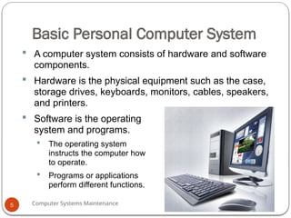
A computer system consists of hardware and software
components.
Hardware is the physical equipment such as the case,
storage drives, keyboards, monitors, cables, speakers,
and printers.
Software is the operating
system and programs.
The operating system
instructs the computer how
to operate.
Programs or applications
perform different functions.
5
6.
Computer Systems Maintenance
ComputerCases and Power Supplies
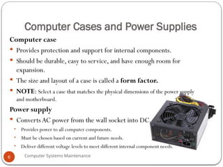
Computer case
Provides protection and support for internal components.
Should be durable, easy to service, and have enough room for
expansion.
The size and layout of a case is called a form factor.
NOTE: Select a case that matches the physical dimensions of the power supply
and motherboard.
Power supply
Converts AC power from the wall socket into DC.
• Provides power to all computer components.
• Must be chosen based on current and future needs.
• Deliver different voltage levels to meet different internal component needs.
6
Computer Systems Maintenance
FourBasic Units of Electricity
Voltage (V) is a measure of the force required to push electrons
through a circuit.Voltage is measured in volts (V).A computer
power supply usually produces several different voltages.
Current (I) is a measure of the amount of electrons going through
a circuit. Current is measured in amperes, or amps (A). Computer
power supplies deliver different amperages for each output voltage.
Power (P) is voltage multiplied by current.The measurement is
called watts (W). Computer power supplies are rated in watts.
Resistance (R) is the opposition to the flow of current in a
circuit. Resistance is measured in ohms (Ω). Lower resistance
allows more current to flow through a circuit.
8
9.
Computer Systems Maintenance
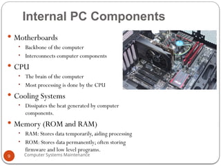
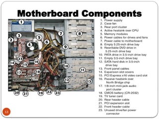
InternalPC Components
Motherboards
• Backbone of the computer
• Interconnects computer components
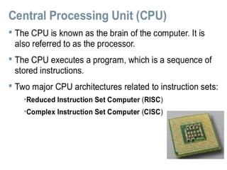
CPU
• The brain of the computer
• Most processing is done by the CPU
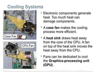
Cooling Systems
• Dissipates the heat generated by computer
components.
Memory (ROM and RAM)
• RAM: Stores data temporarily, aiding processing
• ROM: Stores data permanently; often storing
firmware and low level programs.
9
10.
Computer Systems Maintenance
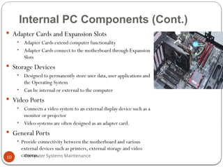
InternalPC Components (Cont.)
Adapter Cards and Expansion Slots
• Adapter Cards extend computer functionality
• Adapter Cards connect to the motherboard through Expansion
Slots
Storage Devices
• Designed to permanently store user data, user applications and
the Operating System
• Can be internal or external to the computer
Video Ports
• Connects a video system to an external display device such as a
monitor or projector
• Video systems are often designed as an adapter card.
General Ports
• Provide connectivity between the motherboard and various
external devices such as printers, external storage and video
cameras.
10
11.
Computer Systems Maintenance
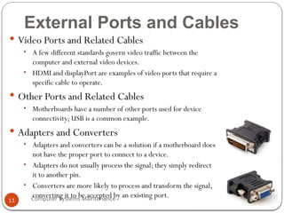
ExternalPorts and Cables
Video Ports and Related Cables
• A few different standards govern video traffic between the
computer and external video devices.
• HDMI and displayPort are examples of video ports that require a
specific cable to operate.
Other Ports and Related Cables
• Motherboards have a number of other ports used for device
connectivity; USB is a common example.
Adapters and Converters
• Adapters and converters can be a solution if a motherboard does
not have the proper port to connect to a device.
• Adapters do not usually process the signal; they simply redirect
it to another pin.
• Converters are more likely to process and transform the signal,
converting it to be accepted by an existing port.
11
Computer Systems Maintenance
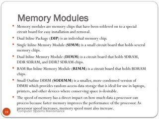
MemoryModules
Memory modules are memory chips that have been soldered on to a special
circuit board for easy installation and removal.
Dual Inline Package (DIP) is an individual memory chip.
Single Inline Memory Module (SIMM) is a small circuit board that holds several
memory chips.
Dual Inline Memory Module (DIMM) is a circuit board that holds SDRAM,
DDR SDRAM, and DDR2 SDRAM chips.
RAM Bus Inline Memory Module (RIMM) is a circuit board that holds RDRAM
chips.
Small Outline DIMM (SODIMM) is a smaller, more condensed version of
DIMM which provides random access data storage that is ideal for use in laptops,
printers, and other devices where conserving space is desirable.
The speed of memory has a direct impact on how much data a processor can
process because faster memory improves the performance of the processor.As
processor speed increases, memory speed must also increase.
19
20.
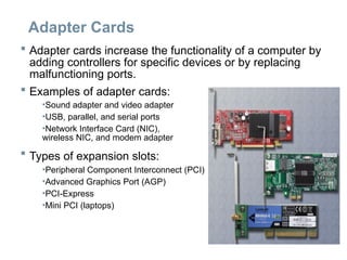
Adapter Cards
Adaptercards increase the functionality of a computer by
adding controllers for specific devices or by replacing
malfunctioning ports.
Examples of adapter cards:
•Sound adapter and video adapter
•USB, parallel, and serial ports
•Network Interface Card (NIC),
wireless NIC, and modem adapter
Types of expansion slots:
•Peripheral Component Interconnect (PCI)
•Advanced Graphics Port (AGP)
•PCI-Express
•Mini PCI (laptops)
21.
Optical Drives, FlashDrives and Drive
Interfaces
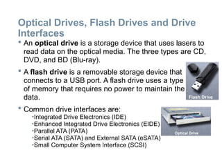
An optical drive is a storage device that uses lasers to
read data on the optical media. The three types are CD,
DVD, and BD (Blu-ray).
A flash drive is a removable storage device that
connects to a USB port. A flash drive uses a type
of memory that requires no power to maintain the
data.
Common drive interfaces are:
•Integrated Drive Electronics (IDE)
•Enhanced Integrated Drive Electronics (EIDE)
•Parallel ATA (PATA)
•Serial ATA (SATA) and External SATA (eSATA)
•Small Computer System Interface (SCSI)
22.
Internal Cables
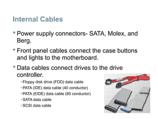
Powersupply connectors- SATA, Molex, and
Berg.
Front panel cables connect the case buttons
and lights to the motherboard.
Data cables connect drives to the drive
controller.
• Floppy disk drive (FDD) data cable
• PATA (IDE) data cable (40 conductor)
• PATA (EIDE) data cable (80 conductor)
• SATA data cable
• SCSI data cable
23.
Video Ports andCables
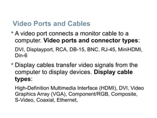
A video port connects a monitor cable to a
computer. Video ports and connector types:
DVI, Displayport, RCA, DB-15, BNC, RJ-45, MiniHDMI,
Din-6
Display cables transfer video signals from the
computer to display devices. Display cable
types:
High-Definition Multimedia Interface (HDMI), DVI, Video
Graphics Array (VGA), Component/RGB, Composite,
S-Video, Coaxial, Ethernet,
24.
Ports and Cables
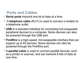
Serial ports transmit one bit of data at a time.
A telephone cable (RJ11) is used to connect a modem to
a telephone outlet.
USB is a standard interface for connecting hot-swappable
peripheral devices to a computer. Some devices can also
be powered through the USB port.
FireWire is a high-speed, hot-swappable interface that can
support up to 63 devices. Some devices can also be
powered through the FireWire port.
A parallel cable is used to connect parallel devices, such
as a printer or scanner, and can transmit 8 bits of data at
one time.
25.
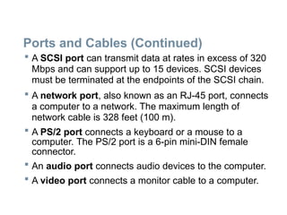
Ports and Cables(Continued)
A SCSI port can transmit data at rates in excess of 320
Mbps and can support up to 15 devices. SCSI devices
must be terminated at the endpoints of the SCSI chain.
A network port, also known as an RJ-45 port, connects
a computer to a network. The maximum length of
network cable is 328 feet (100 m).
A PS/2 port connects a keyboard or a mouse to a
computer. The PS/2 port is a 6-pin mini-DIN female
connector.
An audio port connects audio devices to the computer.
A video port connects a monitor cable to a computer.
26.
Test : ComputerCare and maintenance
Attempt the following questions
1) a) write short notes about the following internal
components of a personal computer
i. Mother board (4 marks)
ii. Central processing unit (4 marks)
iii. Memory (4 marks)
b) using a table outline the difference between video
ports, adapters and converters
(8 marks)
2) Explain the purpose of safe working conditions
and procedures (10 marks)
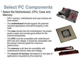
Select PC Components
Select the Motherboard, CPU, Case and
Memory
• CPU, memory, motherboard and case choices are
inter-related.
• The motherboard should support all customer
required applications and still fit properly in the
case.
• The case should host the motherboard, the proper
power supply and provide good airflow for the
internal components.
• The CPU must be compatible with motherboard
CPU slot and voltage; it should be compatible with
the chosen memory speed for maximum
performance.
• The memory must also be compatible with
motherboard memory slots and voltage.
• The amount of memory will depend on the type of
applications requested by the customer.
29.
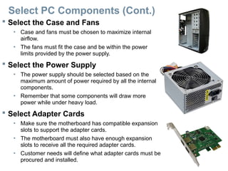
Select PC Components(Cont.)
Select the Case and Fans
• Case and fans must be chosen to maximize internal
airflow.
• The fans must fit the case and be within the power
limits provided by the power supply.
Select the Power Supply
• The power supply should be selected based on the
maximum amount of power required by all the internal
components.
• Remember that some components will draw more
power while under heavy load.
Select Adapter Cards
• Make sure the motherboard has compatible expansion
slots to support the adapter cards.
• The motherboard must also have enough expansion
slots to receive all the required adapter cards.
• Customer needs will define what adapter cards must be
procured and installed.
30.
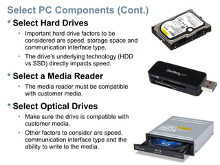
Select PC Components(Cont.)
Select Hard Drives
• Important hard drive factors to be
considered are speed, storage space and
communication interface type.
• The drive’s underlying technology (HDD
vs SSD) directly impacts speed.
Select a Media Reader
• The media reader must be compatible
with customer media.
Select Optical Drives
• Make sure the drive is compatible with
customer media.
• Other factors to consider are speed,
communication interface type and the
ability to write to the media.
31.
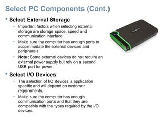
Select PC Components(Cont.)
Select External Storage
• Important factors when selecting external
storage are storage space, speed and
communication interface.
• Make sure the computer has enough ports to
accommodate the external devices and
peripherals.
• Note: Some external devices do not require an
external power supply but rely on a second
USB port for power.
Select I/O Devices
• The selection of I/O devices is application
specific and will depend on customer
requirements.
• Make sure the computer has enough
communication ports and that they are
compatible with the types required by the I/O
devices.
Computer Systems Maintenance
SpecializedComputer Systems
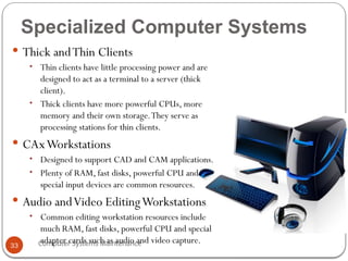
Thick andThin Clients
• Thin clients have little processing power and are
designed to act as a terminal to a server (thick
client).
• Thick clients have more powerful CPUs, more
memory and their own storage.They serve as
processing stations for thin clients.
CAxWorkstations
• Designed to support CAD and CAM applications.
• Plenty of RAM, fast disks, powerful CPU and
special input devices are common resources.
Audio andVideo EditingWorkstations
• Common editing workstation resources include
much RAM, fast disks, powerful CPU and special
adapter cards such as audio and video capture.
33
34.
Computer Systems Maintenance
SpecializedComputer Systems (Cont.)
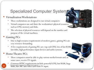
VirtualizationWorkstations
• These workstations are designed to run virtual computers
• Virtual computers use and share the workstation’s physical resources
such as CPU, memory and disks.
• The selection of physical resources will depend on the number and
purpose of the virtual machines.
Gaming PCs
• Due to high resource requirements of modern games, gaming PCs are
very resource demanding.
• A few requirements of gaming PCs are: top end CPU, lots of fast RAM,
fast disks, high performance input devices and audio systems.
HomeTheatre PCs
• These computers must be able to play various media formats and, in
some cases, receiveTV signals.
• Common HTPC requirements include powerful CPU, fast RAM, large
disks, fast NIC and video card withTV input.
34
Computer Systems Maintenance
Lecture2 Objectives
Explain the purpose of safe working
conditions and safe lab procedures
Identify tools and software used with
personal computer components and
their purposes
Demonstrate proper tool use
36
37.
Computer Systems Maintenance
SafeLab Procedures
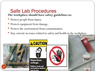
The workplace should have safety guidelines to:
Protect people from injury.
Protect equipment from damage.
Protect the environment from contamination.
Stay current on issues related to safety and health in the workplace.
37
38.
Computer Systems Maintenance
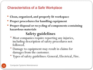
Characteristicsof a Safe Workplace
Clean, organized, and properly lit workspace
Proper procedures for handling equipment
Proper disposal or recycling of components containing
hazardous materials
Safety guidelines
• Most companies require reporting any injuries,
including description of safety procedures not
followed.
• Damage to equipment may result in claims for
damages from the customer.
• Types of safety guidelines: General, Electrical, Fire.
38
39.
Computer Systems Maintenance
SafeLab Procedures
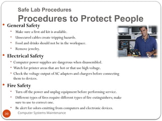
Procedures to Protect People
General Safety
• Make sure a first-aid kit is available.
• Unsecured cables create tripping hazards.
• Food and drinks should not be in the workspace.
• Remove jewelry.
Electrical Safety
• Computer power supplies are dangerous when disassembled.
• Watch for printer areas that are hot or that use high voltage.
• Check the voltage output ofAC adapters and chargers before connecting
them to devices.
Fire Safety
• Turn off the power and unplug equipment before performing service.
• Different types of fires require different types of fire extinguishers; make
sure to use to correct one.
• Be alert for odors emitting from computers and electronic devices.
39
40.
Computer Systems Maintenance
SafeLab Procedures
Procedures to Protect Equipment and Data
• ESD can cause damage to computer equipment if
not discharged properly.
• ESD can build up on you as you walk on a carpeted
floor.
• EMI distorts the signals, degrading computer
communication.
• EMI can be generated by large motors, power lines,
electrical storms, or any other source of
electromagnetic energy.
• Wireless networks are affected by RFI.
• RFI is caused by radio transmitters transmitting in
the same frequency.
Environmental temperature and
humidity levels also affect
computers
Electrostatic Discharge (ESD) and Electromagnetic Interference
(EMI)
40
41.
Computer Systems Maintenance
SafeLab Procedures
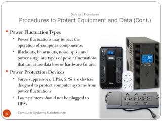
Procedures to Protect Equipment and Data (Cont.)
Power FluctuationTypes
• Power fluctuations may impact the
operation of computer components.
• Blackouts, brownouts, noise, spike and
power surge are types of power fluctuations
that can cause data loss or hardware failure.
Power Protection Devices
• Surge suppressors, UPSs, SPSs are devices
designed to protect computer systems from
power fluctuations.
• Laser printers should not be plugged to
UPSs
41
42.
Computer Systems Maintenance
Thetypes of AC power fluctuations can cause data loss or hardware
failure :
Blackout: Complete loss ofAC power.A blown fuse, damaged transformer, or downed power
line can cause a blackout.
Brownout: Reduced voltage level ofAC power that lasts for a period of time. Brownouts occur
when the power line voltage drops below 80 percent of the normal voltage level. Overloading
electrical circuits can cause a brownout.
Noise: Interference from generators and lightning. Noise results in poor quality power, which
can cause errors in a computer system.
Spike: Sudden increase in voltage that lasts for a short period and exceeds 100 percent of the
normal voltage on a line. Spikes can be caused by lightning strikes but can also occur when the
electrical system comes back on after a blackout.
Power surge: Dramatic increase in voltage above the normal flow of electrical current.A power
surge lasts for a few nanoseconds, or one-billionth of a second .
42
43.
Computer Systems Maintenance
SafeLab Procedures
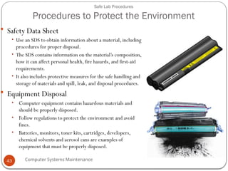
Procedures to Protect the Environment
Safety Data Sheet
• Use an SDS to obtain information about a material, including
procedures for proper disposal.
• The SDS contains information on the material’s composition,
how it can affect personal health, fire hazards, and first-aid
requirements.
• It also includes protective measures for the safe handling and
storage of materials and spill, leak, and disposal procedures.
Equipment Disposal
• Computer equipment contains hazardous materials and
should be properly disposed.
• Follow regulations to protect the environment and avoid
fines.
• Batteries, monitors, toner kits, cartridges, developers,
chemical solvents and aerosol cans are examples of
equipment that must be properly disposed.
43
Computer Systems Maintenance
ProperUse of Tools
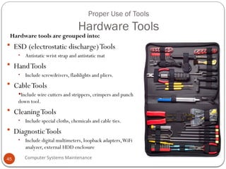
Hardware Tools
Hardware tools are grouped into:
ESD (electrostatic discharge)Tools
• Antistatic wrist strap and antistatic mat
HandTools
• Include screwdrivers, flashlights and pliers.
CableTools
Include wire cutters and strippers, crimpers and punch
down tool.
CleaningTools
• Include special cloths, chemicals and cable ties.
DiagnosticTools
• Include digital multimeters, loopback adapters,WiFi
analyzer, external HDD enclosure
45
46.
Computer Systems Maintenance
ProperUse of Tools
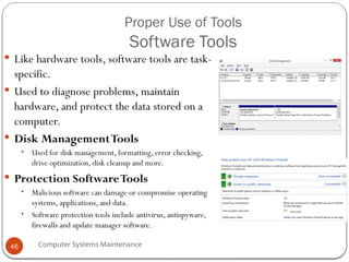
Software Tools
Like hardware tools, software tools are task-
specific.
Used to diagnose problems, maintain
hardware, and protect the data stored on a
computer.
Disk ManagementTools
• Used for disk management, formatting, error checking,
drive optimization, disk cleanup and more.
Protection SoftwareTools
• Malicious software can damage or compromise operating
systems, applications, and data.
• Software protection tools include antivirus, antispyware,
firewalls and update manager software.
46
47.
Computer Systems Maintenance
ProperUse of Tools
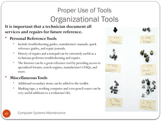
Organizational Tools
It is important that a technician document all
services and repairs for future reference.
Personal ReferenceTools
• Include troubleshooting guides, manufacturer manuals, quick
reference guides, and repair journals.
• History of repairs and a notepad can be extremely useful as a
technician performs troubleshooting and repairs.
• The Internet can be a great reference tool by providing access to
specialized forums, search engines, manufacturer’s FAQs, and
more.
MiscellaneousTools
• Additional secondary items can be added to the toolkit.
• Masking tape, a working computer and even pencil eraser can be
very useful additions to a technician’s kit.
47
Computer Systems Maintenance
Lecture4 Objectives
Open the case
Install the power supply
Attach the components to the motherboard and install the motherboard
Install internal drives and drives in external bays
Install adapter cards
Install and connect all internal cables
Re-attach the side panels and connect external cables to the computer
Boot the computer for the first time
Configure BIOS
49
50.
Computer Systems Maintenance
Lecture4 Objectives
Describe reasons for upgrading computer components
Select and install replacement or upgraded motherboard, CPU,
heat sink and fan, and RAM
Upgrade and configure BIOS
Select and install replacement or upgraded hard drives
Select and install replacement or upgraded input and output
devices
50
51.
Computer Systems Maintenance
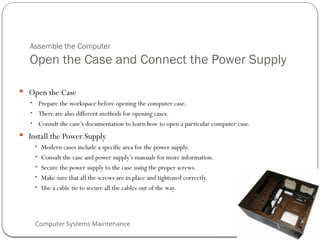
Assemblethe Computer
Open the Case and Connect the Power Supply
Open the Case
• Prepare the workspace before opening the computer case.
• There are also different methods for opening cases.
• Consult the case’s documentation to learn how to open a particular computer case.
Install the Power Supply
• Modern cases include a specific area for the power supply.
• Consult the case and power supply’s manuals for more information.
• Secure the power supply to the case using the proper screws.
• Make sure that all the screws are in place and tightened correctly.
• Use a cable tie to secure all the cables out of the way.
51
52.
Computer Systems Maintenance
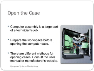
Openthe Case
Computer assembly is a large part
of a technician's job.
Prepare the workspace before
opening the computer case.
There are different methods for
opening cases. Consult the user
manual or manufacturer's website.
52
53.
Computer Systems Maintenance
Installthe Power Supply
Power supply installation steps include the following:
1. Insert the power supply into the case.
2. Align the holes in the power supply with the holes in
the case.
3. Secure the power
supply to the case
using the proper
screws.
53
54.
Computer Systems Maintenance
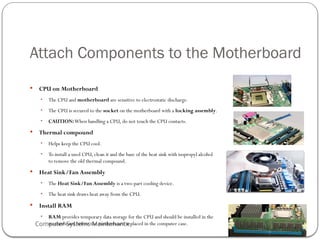
AttachComponents to the Motherboard
CPU on Motherboard
• The CPU and motherboard are sensitive to electrostatic discharge.
• The CPU is secured to the socket on the motherboard with a locking assembly.
• CAUTION:When handling a CPU, do not touch the CPU contacts.
Thermal compound
• Helps keep the CPU cool.
• To install a used CPU, clean it and the base of the heat sink with isopropyl alcohol
to remove the old thermal compound.
Heat Sink/Fan Assembly
• The Heat Sink/Fan Assembly is a two-part cooling device.
• The heat sink draws heat away from the CPU.
Install RAM
• RAM provides temporary data storage for the CPU and should be installed in the
motherboard before the motherboard is placed in the computer case.
54
55.
Computer Systems Maintenance
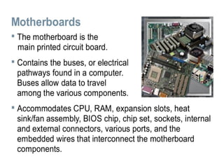
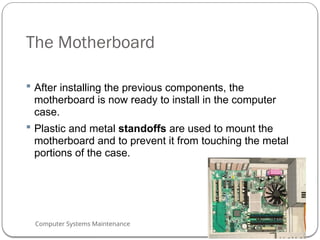
TheMotherboard
After installing the previous components, the
motherboard is now ready to install in the computer
case.
Plastic and metal standoffs are used to mount the
motherboard and to prevent it from touching the metal
portions of the case.
55
56.
Computer Systems Maintenance
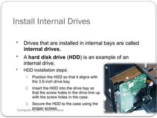
InstallInternal Drives
Drives that are installed in internal bays are called
internal drives.
A hard disk drive (HDD) is an example of an
internal drive.
HDD installation steps:
1. Position the HDD so that it aligns with
the 3.5-inch drive bay.
2. Insert the HDD into the drive bay so
that the screw holes in the drive line up
with the screw holes in the case.
3. Secure the HDD to the case using the
proper screws.
56
57.
Computer Systems Maintenance
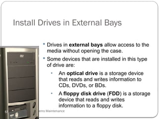
InstallDrives in External Bays
Drives in external bays allow access to the
media without opening the case.
Some devices that are installed in this type
of drive are:
• An optical drive is a storage device
that reads and writes information to
CDs, DVDs, or BDs.
• A floppy disk drive (FDD) is a storage
device that reads and writes
information to a floppy disk.
57
58.
Computer Systems Maintenance
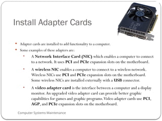
InstallAdapter Cards
Adapter cards are installed to add functionality to a computer.
Some examples of these adapters are:
• A Network Interface Card (NIC) which enables a computer to connect
to a network. It uses PCI and PCIe expansion slots on the motherboard.
• A wireless NIC enables a computer to connect to a wireless network.
Wireless NICs use PCI and PCIe expansion slots on the motherboard.
Some wireless NICs are installed externally with a USB connector.
• A video adapter card is the interface between a computer and a display
monitor.An upgraded video adapter card can provide better graphic
capabilities for games and graphic programs.Video adapter cards use PCI,
AGP, and PCIe expansion slots on the motherboard.
58
59.
Computer Systems Maintenance
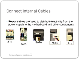
ConnectInternal Cables
Power cables are used to distribute electricity from the
power supply to the motherboard and other components.
ATX
AUX Berg
SATA Molex
59
60.
Computer Systems Maintenance
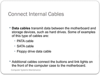
ConnectInternal Cables
Data cables transmit data between the motherboard and
storage devices, such as hard drives. Some of examples
of this type of cables are:
• PATA cable
• SATA cable
• Floppy drive data cable
Additional cables connect the buttons and link lights on
the front of the computer case to the motherboard.
60
61.
Computer Systems Maintenance
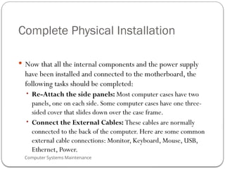
CompletePhysical Installation
Now that all the internal components and the power supply
have been installed and connected to the motherboard, the
following tasks should be completed:
• Re-Attach the side panels: Most computer cases have two
panels, one on each side. Some computer cases have one three-
sided cover that slides down over the case frame.
• Connect the External Cables: These cables are normally
connected to the back of the computer. Here are some common
external cable connections: Monitor, Keyboard, Mouse, USB,
Ethernet, Power.
61
Computer Systems Maintenance
Bootthe Computer
POST, BIOS, UEFI
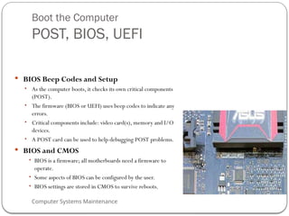
BIOS Beep Codes and Setup
• As the computer boots, it checks its own critical components
(POST).
• The firmware (BIOS or UEFI) uses beep codes to indicate any
errors.
• Critical components include: video card(s), memory and I/O
devices.
• A POST card can be used to help debugging POST problems.
BIOS and CMOS
• BIOS is a firmware; all motherboards need a firmware to
operate.
• Some aspects of BIOS can be configured by the user.
• BIOS settings are stored in CMOS to survive reboots.
63
64.
Computer Systems Maintenance
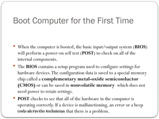
BootComputer for the First Time
When the computer is booted, the basic input/output system (BIOS)
will perform a power-on self test (POST) to check on all of the
internal components.
The BIOS contains a setup program used to configure settings for
hardware devices.The configuration data is saved to a special memory
chip called a complementary metal-oxide semiconductor
(CMOS) or can be saved in nonvolatile memory which does not
need power to retain settings.
POST checks to see that all of the hardware in the computer is
operating correctly. If a device is malfunctioning, an error or a beep
code alerts the technician that there is a problem.
64
65.
Computer Systems Maintenance
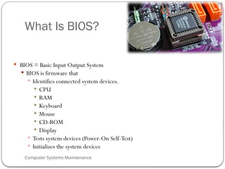
WhatIs BIOS?
BIOS = Basic Input Output System
BIOS is firmware that
Identifies connected system devices.
CPU
RAM
Keyboard
Mouse
CD-ROM
Display
Tests system devices (Power-On Self-Test)
Initializes the system devices
65
66.
Computer Systems Maintenance
BIOSConfiguration
Technicians use the BIOS information to learn about installed components:
• CPU – Manufacturer and speed
• RAM - Manufacturer and speed
• Hard Drive - Manufacturer, size, and type
• Optical Drive - manufacturer and type
Technicians use BIOS to:
• SetTime and Date
• Disable Devices
• Set Boot Order
• Adjust Clock Speed
• EnableVirtualization
66
67.
Computer Systems Maintenance
BIOSConfiguration
Technicians can set the following BIOS security features
BIOS passwords
Drive encryption
Trusted Platform Module (TPM)
Lojack
• Lock the computer remotely.
• Display a message so that a lost computer can be returned to
the owner.
• Delete sensitive data on the computer if stolen.
• Locate the computer using geotechnology.
67
68.
Computer Systems Maintenance
BIOSConfiguration
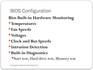
Bios Built-in Hardware Monitoring
Temperatures
Fan Speeds
Voltages
Clock and Bus Speeds
Intrusion Detection
Built-in Diagnostics
Start test, Hard drive test, Memory test
68
69.
Computer Systems Maintenance
Thereare several ways to determine who the BIOS manufacturer is:
Watch the monitor when the computer boots.
Check the computer or motherboard manual.
Remove the cover of the computer and look at the chip.
Reboot the computer and hold down several keys at once or
unplug a drive.
69
70.
Computer Systems Maintenance
BIOSSettings and Screens
Common methods to access the BIOS/CMOS editor during bootup:
Esc
Del
F1
F2
F10
Ctrl+Alt+?
Most system splash screens provide information on which key to press.
When in doubt, consult the motherboard manual.
70
71.
Computer Systems Maintenance
MotherboardComponent Upgrades
If the motherboard is upgraded or replaced, the CPU may
need to be replaced
CPU architectures are installed in these common socket
connection designs:
• Zero-Insertion Force (ZIF)
• Land Grid Array (LGA)
• Pin Grid Array (PGA)
• Single-Edge Connector (SEC) – no longer commonly used
• Low-Insertion Force (LIF) - no longer commonly used
71
72.
Computer Systems Maintenance
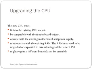
Upgradingthe CPU
The new CPU must:
fit into the existing CPU socket.
be compatible with the motherboard chipset.
operate with the existing motherboard and power supply.
must operate with the existing RAM.The RAM may need to be
upgraded or expanded to take advantage of the faster CPU.
might require a different heat sink and fan assembly.
72
73.
Computer Systems Maintenance
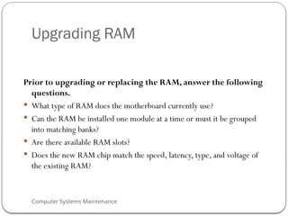
UpgradingRAM
Prior to upgrading or replacing the RAM, answer the following
questions.
What type of RAM does the motherboard currently use?
Can the RAM be installed one module at a time or must it be grouped
into matching banks?
Are there available RAM slots?
Does the new RAM chip match the speed, latency, type, and voltage of
the existing RAM?
73
74.
Computer Systems Maintenance
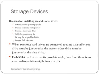
StorageDevices
Reasons for installing an additional drive:
• Install a second operating system
• Provide additional storage space
• Provide a faster hard drive
• Hold the system swap file
• Back up the original hard drive
• Increase fault tolerance
When two PATA hard drives are connected to same data cable, one
drive must be jumpered as the master, other drive must be
jumpered as the slave drive.
Each SATA hard drive has its own data cable, therefore, there is no
master-slave relationship between drives
74
75.
Computer Systems Maintenance
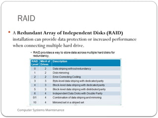
RAID
A Redundant Array of Independent Disks (RAID)
installation can provide data protection or increased performance
when connecting multiple hard drive.
75
76.
Computer Systems Maintenance
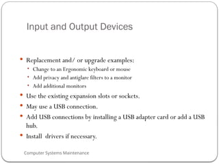
Inputand Output Devices
Replacement and/ or upgrade examples:
• Change to an Ergonomic keyboard or mouse
• Add privacy and antiglare filters to a monitor
• Add additional monitors
Use the existing expansion slots or sockets.
May use a USB connection.
Add USB connections by installing a USB adapter card or add a USB
hub.
Install drivers if necessary.
76
Computer Systems Maintenance
Lecture5 Objectives
Preventive Maintenance
Why preventive maintenance must be performed on personal
computers.
Troubleshooting Process
How to troubleshoot computer problems.
78
79.
Computer Systems Maintenance
ThePurpose of Preventive Maintenance
Reduce the possibility of hardware or software problems by
implementing a preventive Maintenance Plan based on at least
two factors:
• Computer location
• Computer use
Benefits of Preventive Maintenance are:
• Reduced computer down time and repair costs.
• Increased data protection.
• Extended life of the components.
• Increased equipment stability.
Preventive Maintenance can be divided into:
• Hardware maintenance
• Software maintenance
79
80.
Computer Systems Maintenance
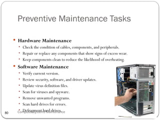
PreventiveMaintenance Tasks
Hardware Maintenance
• Check the condition of cables, components, and peripherals.
• Repair or replace any components that show signs of excess wear.
• Keep components clean to reduce the likelihood of overheating.
Software Maintenance
• Verify current version.
• Review security, software, and driver updates.
• Update virus definition files.
• Scan for viruses and spyware.
• Remove unwanted programs.
• Scan hard drives for errors.
• Defragment hard drives.
80
81.
Computer Systems Maintenance
PreventiveMaintenance
PC Preventive Maintenance Overview (Cont.)
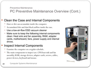
Clean the Case and Internal Components
• Dust or dirt can accumulate inside the computer.
• Accumulated dirt and dust block airflow inside the case.
• Use a low-air-flow ESD vacuum cleaner
• Make sure to keep the following internal components
clean: Heat sink and fan assembly, RAM, adapter
cards, motherboard, fans, power supply and internal
drives.
Inspect Internal Components
• Examine the computer on a regular schedule.
• The main components to inspect are: CPU heat sink and fan
assembly, RAM, storage devices, adapter cards, screws, cables,
power devices, keyboard and mouse.
81
82.
Computer Systems Maintenance
PreventiveMaintenance
PC Preventive Maintenance Overview (Cont.)
Environmental Concerns
• Computers should not be operated in harsh environmental
conditions.
• Due to their mobile nature, laptops are subject to various
environmental conditions.
Guidelines to help ensure optimal computer
operating performance include:
• Do not obstruct vents or airflow to the internal
components.
• Keep the room temperature between 45 to 90 degrees
Fahrenheit (7 to 32 degrees Celsius).
• Keep the humidity level between 10 and 80 percent.
82
83.
Computer Systems Maintenance
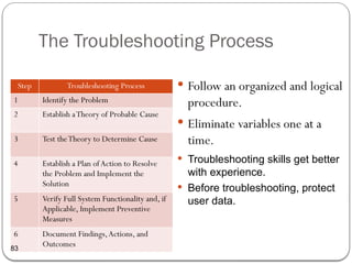
TheTroubleshooting Process
Follow an organized and logical
procedure.
Eliminate variables one at a
time.
Troubleshooting skills get better
with experience.
Before troubleshooting, protect
user data.
Step Troubleshooting Process
1 Identify the Problem
2 Establish aTheory of Probable Cause
3 Test theTheory to Determine Cause
4 Establish a Plan ofAction to Resolve
the Problem and Implement the
Solution
5 Verify Full System Functionality and, if
Applicable, Implement Preventive
Measures
6 Document Findings,Actions, and
Outcomes
83
84.
Computer Systems Maintenance
TroubleshootingProcess
Troubleshooting Process Steps
Identify the Problem
• Ask the customer questions and be respectful.
• Use both open-ended and closed-ended questions.
• Listen to beep codes.
• Use BIOS or UEFI to identify POST problems.
• Use EventViewer, Device Manager,Task Manager
and other diagnostics tools to help identifying the
problem.
84
85.
Computer Systems Maintenance
TroubleshootingProcess
Troubleshooting Process Steps (Cont.)
Establish a Theory of Probable Cause
• Create a list of the most common reasons for the error.
• List the easiest or most obvious causes at the top and more
complex causes at the bottom.
• Research the symptoms.
Test the Theory to Determine Cause
• Test your theories one at a time.
• If none of the theories can be confirmed, create new ones.
Establish a Plan of Action to Resolve the
Problem and Implement the Solution
• Write down a plan to solve the identified problem.
• May require simple or complex procedures.
85
86.
Computer Systems Maintenance
TroubleshootingProcess
Troubleshooting Process Steps (Cont.)
Verify Full System Functionality and, if
applicable, Implement Preventive
Measures
• The troubleshooting process is not over until full system
functionality is confirmed.
• If the system is working properly, implement preventive measures
if needed.
Document Findings, Actions and
Outcomes
• Explain the problem to the customer, both verbally and in writing.
• The customer should try to reproduce the problem after the
solution has been implemented.
• Document the entire process for future reference.
86
87.
Computer Systems Maintenance
TroubleshootingProcess
Common Problems and Solutions
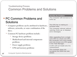
PC Common Problems and
Solutions
• Computer problems can be attributed to hardware,
software, networks, or some combination of the
three.
• Common PC hardware problems include:
Storage device problems
Motherboard and internal components
problems
Power supply problems
CPU and memory problems
87
88.
Computer Systems Maintenance
PCCommon Problems and Solutions
Storage device problems - loose or incorrect cable
connections, incorrect drive and media formats, and incorrect
jumper and BIOS settings.
Motherboard and internal component problems -
incorrect or loose cables, failed components, incorrect drivers, and
corrupted updates.
Power supply problems - faulty power supply, loose
connections, and inadequate wattage.
CPU and memory problems - faulty installations, incorrect
BIOS settings, inadequate cooling and ventilation, and
compatibility issues.
88
89.
Computer Systems Maintenance
Lecture5 Summary
Regular preventive maintenance reduces hardware and
software problems.
Before beginning any repair, back up the data on a
computer.
The troubleshooting process is a guideline to help solve
computer problems in a logical and efficient manner.
Document every solution that is tried, even if it fails.The
documentation that is created will become a useful
resource.
89
#5 1.0.1.1 Describe a computer system
Chapter 1 will review the components of a basic personal computer system and specialized computer systems.
#6 1.1.1.1 Describe Computer cases
Computer Cases and Power Supplies
Identify the names, purposes, and characteristics of cases and power supplies
Computer case
Provides protection and support for the internal components of the computer.
Should be durable, easy to service, and have enough room for expansion
The size and shape of the computer case is usually determined by the motherboard and other internal components.
1.1.1.2 Describe power supplies
Power supply
A power inverter located within the power supply converts alternating-current (AC) power coming from a wall outlet into direct-current (DC) power, which is a lower voltage.
DC power is required for all of the components inside the computer.
Cables, connectors, and components are designed to fit together snugly.
Never force any connector or component.
Molex connector is a keyed connector used to connect to an optical drive or a hard drive.
Berg connector is a keyed connector used to connect to a floppy drive. A Berg connector is smaller than a Molex connector.
#7 It provides instant feedback by showing text and graphic images.
Due to the slimmer design and smaller energy consumption LCDs are starting to replace CRTs on many desktops.
#8 1.1.1.3 Electricity
These are the four basic units of electricity:
Voltage (V)
Current (I)
Power (P)
Resistance (R)
Voltage, current, power, and resistance are electronic terms that a computer technician must know:
Voltage is a measure of the force required to push electrons through a circuit. Voltage is measured in volts (V). A computer power supply usually produces several different voltages.
Current (I) is a measure of the amount of electrons going through a circuit. Current is measured in amperes, or amps (A). Computer power supplies deliver different amperages for each output voltage.
Power is a measure of the force required to push electrons through a circuit, called voltage, multiplied by the number of electrons going through that circuit, called current. The measurement is called watts (W). Computer power supplies are rated in watts.
Resistance is the opposition to the flow of current in a circuit. Resistance is measured in ohms (Ω). Lower resistance allows more current, and therefore more power, to flow through a circuit. A good fuse will have low resistance or a measurement of almost 0 ohms.
#9 1.1 - Personal Computer Systems
1.1.2 - Internal PC Components
#10 1.1 - Personal Computer Systems
1.1.2 - Internal PC Components (Cont.)
#11 1.1 - Personal Computer Systems
1.1.3 - External Ports and Cables
#19 1.1.2.6 Memory Modules
Early computers had RAM installed on the motherboard as individual chips. The individual memory chips, called dual inline package (DIP) chips, were difficult to install and often became loose on the motherboard. Memory modules solved this problem.
NOTE: Memory modules can be single-sided or double-sided. Single-sided memory modules only contain RAM on one side of the module. Double-sided memory modules contain RAM on both sides of the module.
Single-channel memory is capable of transferring data at 64 bits. Dual-channel memory increases speed by using a second channel of memory, creating a data transfer rate of 128 bits.
Double Data Rate (DDR) technology doubles the maximum bandwidth of SDRAM. DDR2 offers faster performance while using less energy. DDR3 operates at even higher speeds than DDR2; however, none of these DDR technologies are backward- or forward-compatible.
#20 1.1.2.7 Identify the names, purposes, and characteristics of adapter cards
NIC - Connects computer to a network using a network cable
Wireless NIC - Connects computer to a network using radio frequencies
Sound adapter - Provides audio capability
Video adapter - Provides graphic capability
Modem adapter - Connects a computer to the Internet using a phone line
USB port - Connects a computer to peripheral devices
Parallel port - Connects a computer to peripheral devices
Serial port - Connects a computer to peripheral devices
Computers have expansion slots on the motherboard to install adapter cards. The type of adapter card connector must match the expansion slot. A riser card was used in computer systems with the LPX form factor to allow adapter cards to be installed horizontally. The riser card was mainly used in slim-line desktop computers. The different types of expansion slots are:
Peripheral Component Interconnect (PCI) is a 32-bit or 64-bit expansion slot. PCI is the standard slot currently used in most computers.
Advanced Graphics Port (AGP) is a 32-bit expansion slot. AGP is designed for video adapters.
PCI-Express is a serial bus expansion slot. PCI-Express is backward compatible with PCI parallel slot. PCI-Express has x1, x4, x8, and x16 slots.
#21 1.1.2.8 Identify the names, purposes, and characteristics of storage devices
CD, DVD, and BD (Blu-ray) media can be pre-recorded (read-only), recordable (write once), or re-recordable (read and write multiple times). CDs have a data storage capacity of approximately 700 MB. DVDs have a data storage capacity of approximately 4.3 GB on a single-layer disc, and approximately 8.5 GB on a dual-layer disc. BDs have a storage capacity of 25 GB on a single-layer disc, and 50 GB on a dual-layer disc.
An external flash drive, also known as a thumb drive, uses a special type of memory that requires no power to maintain the data.
Hard drives and optical drives are manufactured with different interfaces that are used to connect the drive to the computer. To install a storage drive in a computer, the connection interface on the drive must be the same as the controller on the motherboard. Here are some common drive interfaces:
IDE – Integrated Drive Electronics, also called Advanced Technology Attachment (ATA) is an early drive controller interface that connects computers and hard disk drives.
EIDE – Enhanced Integrated Drive Electronics, also called ATA-2, is an updated version of the IDE drive controller interface.
PATA – Parallel ATA refers to the parallel version of the ATA drive controller interface.
SATA – Serial ATA refers to the serial version of the ATA drive controller interface.
eSATA – External Serial ATA provides a hot-swappable, external interface for SATA drives.
SCSI – Small Computer System Interface is a drive controller interface that can connect up to 15 drives. SCSI can connect both internal and external drives.
#22 1.1.2.9 Identify the names, purposes, and characteristics of internal cables
Drives require both a power cable and a data cable. A power supply will have a SATA power connector for SATA drives, a Molex power connector for PATA drives, and a Berg 4-pin connector for floppy drives. The buttons and the LED lights on the front of the case connect to the motherboard with the front panel cables. Data cables connect drives to the drive controller, which is located on an adapter card or on the motherboard.
NOTE: A colored stripe on a floppy or PATA cable identifies Pin 1 on the cable. When installing a data cable, always ensure that Pin 1 on the cable aligns with Pin 1 on the drive or drive controller. Some cables may be keyed and therefore they can only be connected one way to the drive and drive controller.
#23 1.1.3. Identify the names, purposes, and characteristics of External Ports and Cables
1.1.3.1 Identify the names, purposes, and characteristics of Video Ports and cables
Display Cables
High-Definition Multimedia Interface (HDMI) - Carries digital video and digital audio signals. Digital signals provide high-quality video and high resolutions.
DVI - Carries analog, digital, or both analog and digital video signals.
Video Graphics Array (VGA) - Carries analog video signals. Analog video is low quality and can be interfered with by electrical and radio signals.
Component/RGB - Carries analog video signals over three shielded cables.
Composite - Carries analog audio or video signals.
S-Video - Carries analog video signals.
Coaxial - Carries analog, digital, or both analog and digital video or audio signals.
Ethernet - Carries analog, digital, or both analog and digital video or audio signals. Ethernet can also carry power.
Video Connectors - There are several video connector types:
Video Graphics Array (VGA) – VGA has a 3-row 15-pin female connector and provides analog output to a monitor.
Digital Visual Interface (DVI) – DVI has a 24-pin female connector or a 29-pin female connector and provides a compressed digital output to a monitor. DVI-I provides both analog and digital signals. DVI-D provides digital signals only.
High-Definition Multimedia Interface (HDMI) – HDMI has a 19-pin connector and provides digital video and digital audio signals.
S-Video – S-Video has a 4-pin connector and provides analog video signals.
Component/RGB – RGB has three shielded cables (red, green, blue) with RCA jacks and provides analog video signals.
#24 1.1.3.2 Other ports and Cables-Identify the names, purposes, and characteristics of ports and cables
Input/output (I/O) ports on a computer connect peripheral devices, such as printers, scanners, and portable drives.
Serial Ports and Cables - A serial port can be either a DB-9 or a DB-25 male connector. Serial ports transmit one bit of data at a time. To connect a serial device, such as a modem or printer, a serial cable must be used.
A telephone cable (Rj11) is used to connect a modem to a telephone outlet. This cable uses an RJ-11 connector. A setup of an external modem uses a serial cable and a telephone cable.
USB Ports and Cables – The Universal Serial Bus (USB) is a standard interface that connects peripheral devices to a computer. It was originally designed to replace serial and parallel connections. USB devices are hot-swappable, which means that users can connect and disconnect the devices while the computer is powered on. USB connections can be found on computers, cameras, printers, scanners, storage devices, and many other electronic devices. A USB hub is used to connect multiple USB devices.
USB 1.1 allows transmission rates of up to 12 Mbps in full-speed mode. USB 2.0 allows transmission speeds up to 480 Mbps. USB 3.0 allows transmission speeds of 4.8 Gbps. Is backward compatible.
FireWire Ports and Cables - FireWire uses the IEEE 1394 standard and is also known as i.Link. The IEEE 1394a standard supports data rates up to 400 Mbps. The IEEE 1394b standard supports data rates in excess of 800 Mbps.
Parallel Ports and Cables – Parallel ports use the IEEE 1284 standard. To connect a parallel device, such as a printer, a parallel cable must be used.
SCSI Ports and Cables – A SCSI port can transmit data at rates in excess of 320 Mbps and can support up to 15 devices. Check the device manual for termination procedures. Some SCSI connectors resemble parallel connectors. Be careful not to connect the cable to the wrong port. The voltage used in the SCSI format may damage the parallel interface. SCSI connectors should be clearly labeled.
#25 1.1.3.2 Identify the names, purposes, and characteristics of ports and cables
Network Ports and Cables – The connection speed depends on the type of network port. Standard Ethernet can transmit up to 10 Mbps, Fast Ethernet can transmit up to 100 Mbps, and Gigabit Ethernet can transmit up to 1000 Mbps. The maximum length of network cable is 328 feet (100 m).
PS/2 Ports - The connectors for the keyboard and mouse are often colored differently. If the ports are not color-coded, look for a small figure of a mouse or keyboard next to each port.
Audio Ports The following audio ports are commonly used:
Line In – Connects to an external source, such as a stereo system
Microphone – Connects to a microphone
Line Out – Connects to speakers or headphones
Gameport/MIDI – Connects to a joystick or MIDI-interfaced device
#33 1.3 - Configurations for Specialized Computer Systems
1.3.1 - Specialized Computer Systems
#34 1.3 - Configurations for Specialized Computer Systems
1.3.1 - Specialized Computer Systems (Cont.)
#35 Computer Care and Maintenance
Lecture 2: Safe Lab Procedures and Tool Use
#36 Lecture 2 Objectives
The purpose of this lecture is to protect users from accident and injury, equipment from damage, and the environment from contamination. Upon completion of this chapter, students will be able to perform tasks related to:
2.1 Explain the purpose of safe working conditions and procedures
2.2 Identify tools and software used with personal computer components and their purposes
2.2.4 Implement proper tool use
#37 2.1 Explain the purpose of safe working conditions and procedures
Injury prevention is everyone’s responsibility. Stay alert to situations that could result in an injury. Developing and using safe work practices is by far the best method for preventing injuries in the workplace. In order to best prevent injury, follow these simple rules at all times:
Follow all national, industry, and workplace safety rules.
Be alert and be awake. A tired worker can be a danger to one’s self and others.
Training is essential when working with electricity, power tools, or any other potentially hazardous equipment.
Use safety equipment.
Lift with the legs, not the back. Many back injuries are caused by people bending over to lift a heavy object.
The work place is never the place for drugs or alcohol.
Always act professionally. Clowning around or playing practical jokes can result in injury.
Stay current on issues related to safety and health in the workplace.
#38 2.1.1.1 General Safety
Safe working conditions protect users from accident and injury. Proper procedures for handling computer components prevent equipment damage and data from loss. Proper disposal of computer components protects the environment.
Professional technicians follow proper safety procedures. Customers prefer to deal with responsible technicians.
This is a partial list of basic safety precautions to use when working on a computer:
Remove your watch and jewelry and secure loose clothing.
Turn off the power and unplug equipment before performing service.
Cover sharp edges inside the computer case with tape.
Never open a power supply or a CRT monitor.
Do not touch areas in printers that are hot or that use high voltage.
Know where the fire extinguisher is located and how to use it.
Keep food and drinks out of your workspace.
Keep your workspace clean and free of clutter.
Bend your knees when lifting heavy objects to avoid injuring your back.
General Safety Guidelines - Follow the basic safety guidelines to prevent cuts, burns, electrical shock, and damage to eyesight. As is best practice, make sure that a fire extinguisher and first-aid kit are available in case of fire or injury. Poorly placed or unsecured cables usually cause tripping hazards in a network installation. Cables should be installed in conduit or cable trays to prevent hazards to users.
2.1.1.2 Electrical Safety Guidelines - Follow electrical safety guidelines to prevent electrical fires, injuries, and fatalities in the home and the workplace. Power supplies and monitors contain very high voltage. Only experienced technicians should attempt to repair power supplies and monitors, while most users should simply replace them.
2.1.1.3 Fire Safety Guidelines - Follow fire safety guidelines to protect lives, structures, and equipment. To avoid an electrical shock, and to prevent damage to the computer, turn off and unplug the computer before beginning a repair.
Have a fire plan before you begin work:
Know the location of fire extinguishers, how to use them, and which to use for electrical fires and for combustible fires
Have an escape route in case a fire gets out of control
Know how to contact emergency services quickly
Keep the workspace clean
Keep most solvents in a separate area
It is important to know how to use a fire extinguisher. Use the memory aid P-A-S-S to help you remember the basic rules of fire extinguisher operation:
P - Pull the pin.
A - Aim at the base of the fire, not at the flames.
S - Squeeze the lever.
S - Sweep the nozzle from side to side.
#39 2.1 - Safe Lab Procedures
2.1.1 - Procedures to Protect People
#40 2.1 - Safe Lab Procedures
2.1.2 - Procedures to Protect Equipment and Data
#41 2.1.2.2 Power Fluctuation. Voltage is the force that moves electrons through a circuit. The movement of electrons is called current. Computer circuits need voltage and current to operate electronic components. When the voltage in a computer is not accurate or steady, computer components may not operate correctly. Unsteady voltages are called power fluctuations.
The following types of AC power fluctuations can cause data loss or hardware failure:
Blackout - Complete loss of AC power
Brownout - Reduced voltage level of AC power that lasts for a period of time
Noise - Electrical interference from generators and lightning
Spike - Sudden increase in voltage that lasts for a very short period and exceeds 100% of the normal voltage on a line
Power surge - Dramatic increase in voltage above the normal flow of electrical current
2.1.2.3 Power Protection Devices. To help shield against power fluctuation issues, use power protection devices to protect the data and computer equipment:
A surge suppressor helps protect against damage from surges and spikes. A surge suppressor diverts extra electrical voltage on the line to the ground.
Uninterruptible Power Supply (UPS) helps protect against potential electrical power problems by supplying electrical power to a computer or other device.
Standby Power Supply (SPS) helps protect against potential electrical power problems by providing a backup battery to supply power when the incoming voltage drops below the normal level
CAUTION: Never plug a printer into a UPS device. UPS manufacturers suggest not plugging a printer into a UPS for fear of burning up the printer motor.
#43 2.1 - Safe Lab Procedures
2.
2.1.3 Identify safety procedures to protect the environment from contamination
2.1.3.1 Material Safety Data Sheet (MSDS)
Computers and peripherals contain materials that can be harmful to the environment. Hazardous materials are sometimes called toxic waste. These materials can contain high concentrations of heavy metals such as cadmium, lead, or mercury. The regulations for the disposal of hazardous materials vary according to state or country. Contact the local recycling or waste removal authorities in your community for information about disposal procedures and services.
MSDS is a fact sheet summarizing information about material identification, including hazardous ingredients that can affect personal health, fire hazards, and first aid requirements.
The name of the material
The physical properties of the material
Any hazardous ingredients contained in the material
Reactivity data, such as fire and explosion data
Procedures for spills or leaks
Special precautions
Health hazards
Special protection requirements
NOTE: The MSDS is valuable in determining how to dispose of any potentially hazardous materials in the safest manner.
What organization governs the use of hazardous chemicals in your country? Are MSDS sheets mandatory?
2.1.3.2 Equipment Disposal
Batteries from portable computer systems may contain lead, cadmium, lithium, alkaline manganese, and mercury. Recycling batteries should be a standard practice for a technician.
Monitors contain up to 4 pounds of lead, as well as rare earth metals. Monitors must be disposed of in compliance with environmental regulations.
Used printer toner kits and printer cartridges must be disposed of properly or recycled.
Contact the local sanitation company to learn how and where to dispose of the chemicals and solvents used to clean computers.
1.3 - Procedures to Protect the Environment
#45 2.2 – Proper Use of Tools
2.2.1 - Hardware Tools
#46 Identify software tools and their purpose
Disk Management
Fdisk - used to create and delete partitions on a hard drive
Format - used to prepare a hard drive to store information
Scandisk or Chkdsk - used to check the integrity of files and folders on a hard drive by scanning the disk surface for physical errors
Defrag - used to optimize space on a hard drive to allow faster access to programs and data
Disk Cleanup - used to clear space on a hard drive by searching for files that can be safely deleted
Disk Management - a system utility used to manage hard drives and partitions, such as initializing disks, creating partitions, and formatting partitions. Disk Management has the functions of FORMAT and FDISK, and a few more, but it is performed from the Windows GUI interface.
System File Checker (SFC) – a command-line utility that scans the operating system critical files and replaces any files that are corrupted.
Use the Windows 7 boot disk for troubleshooting and repairing corrupted files. The Windows 7 boot disk is designed to repair Windows system files, restore damaged or lost files, or reinstall the operating system. Third-party software tools are available to assist in troubleshooting problems.
Protection Software
Windows 7 Security Center
Antivirus Program
Spyware Remover
Firewall
Worksheet: Diagnostic Software. To complete this worksheet, students will conduct research on hard drive diagnostic programs from at least two different hard drive manufacturers. Answer questions about one of the manufacturer and its diagnostic software.
Identify organizational tools and their purpose
Organizational Tools
It is important that a technician document all services and repairs. The documentation can then be used as reference material for similar problems that are encountered in the future. Good customer service includes providing the customer with a detailed description of the problem and the solution.
Personal reference tools
Notes – Make notes as you go through the investigation and repair process. Refer to these notes to avoid repeating previous steps and to determine what steps to take next.
Journal – Document the upgrades and repairs that you perform. The documentation should include descriptions of the problem, possible solutions that have been tried in order to correct the problem, and the steps taken to repair the problem. Be sure to note any configuration changes made to the equipment and any replacement parts used in the repair. Your journal, along with your notes, can be valuable when you encounter similar situations in the future.
History of repairs – Make a detailed list of problems and repairs, including the date, replacement parts, and customer information. The history allows a technician to determine what work has been performed on a computer in the past.
Internet reference tools - The Internet is an excellent source of information about specific hardware problems and possible solutions:
Internet search engines
News groups
Manufacturer FAQs
Online computer manuals
Online forums and chat
Technical websites
Manufacturer download areas for new drivers
Miscellaneous tools – With experience, you will discover many additional items to add to the toolkit. A working computer is a valuable resource to take with you on computer repairs in the field. A working computer can be used to research information, download tools or drivers, or communicate with other technicians. Using known good working components to replace possible bad ones in computers will help you quickly determine which component may not be working properly.
#47 2.2 – Proper Use of Tools
2.2.3 – Organizational Tools
#51 3.1 - Assemble the Computer
3.1.1 - Open the Case and Connect the Power Supply
#52 Introduction
Computer assembly is a large part of a technician's job.
Work in a logical, methodical manner when working with computer components
Improve computer assembly skills dramatically with practice
Open the case
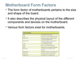
Computer cases are produced in a variety of form factors.
Form factors refer to the size and shape of the case.
Prepare the workspace before opening the computer case:
There should be adequate lighting, good ventilation, and a comfortable room temperature.
The workbench or table should be accessible from all sides.
Avoid cluttering the surface with tools and computer components.
An antistatic mat on the table will help prevent physical and ESD damage to equipment.
Small containers can be used to hold screws and other small parts as they are being removed.
There are different methods for opening cases. To learn how, consult the user manual or manufacturer's website. Some of the methods include the following:
The computer case cover may be removed as one piece.
The top and side panels of the case may be removed.
The top of the case may need to be removed before the side panels can be removed.
#53 3.1.1.2 Install the power supply
A technician may be required to replace or install a power supply. Most power supplies can only fit one way in the computer case. Power supplies have fans that can vibrate and loosen screws that are not secured.
Student Activity
3.1.1.3 Lab-Install the Power Supply: To complete this lab, students will install a power supply in a computer case.
Virtual Desktop Activity: The student course content includes the optional activity, Virtual Desktop Power Supply. To complete this lab, students will complete the power supply layer in the virtual desktop. System requirements for the virtual desktop include a minimum of 512MB RAM.
#54 3.1.2 Attach the components to the motherboard and install the motherboard
As part of an upgrade or repair, you may need to install components on the motherboard, and then install the motherboard into the computer case.
3.1.2.1 Install a CPU and a heat sink/fan assembly
The CPU and the heat sink/fan assembly may be installed on the motherboard before the motherboard is placed in the computer case.
When handling a CPU or motherboard, make sure that you place them on a grounded antistatic mat. You should also wear an antistatic wrist strap.
The CPU is secured to the socket on the motherboard with a locking assembly. The CPU sockets today are ZIF sockets. You should be familiar with the locking assembly before attempting to install a CPU into the socket on the motherboard.
Thermal Compound
It is a substance that increases the transfer of heat from the CPU to the heat sink, where it can be dissipated.
Follow manufacturer’s recommendations about applying the thermal compound.
Install a CPU and a heat sink/fan assembly
The fan moves the heat away from the heat sink.
The heat sink/fan assembly usually has a 3-pin power connector.
To install the CPU and heat sink/fan assembly:
Align the CPU so that the Connection 1 indicator is lined up with Pin 1 on the CPU socket.
Place the CPU gently into the socket.
Close the CPU load plate and secure it by closing the load lever and moving it under the load lever retention tab.
Apply a small amount of thermal compound to the CPU and spread it evenly. Follow the application instructions provided by the manufacturer.
Line up the heat sink/fan assembly retainers to the holes on the motherboard.
Place the heat sink/fan assembly onto the CPU socket, being careful not to pinch the CPU fan wires
Tighten the heat sink/fan assembly retainers to secure the assembly in place
Connect the heat sink/fan assembly power cable to the header on the motherboard
3.1.2.2 Install the RAM
RAM is volatile memory and the contents are lost when the computer is shut down. Typically, adding more RAM will enhance the performance of your computer.
Before you install a stick of RAM, consult the motherboard documentation or website of the manufacturer to ensure that the RAM is compatible with the motherboard.
The following are RAM installation steps:
Align the notches on the RAM module to the keys in the slot and press down until the side tabs click into place.
Make sure that the side tabs have locked the RAM module and visually check for exposed contacts.
Repeat these steps for additional RAM modules.
#55 3.1.2.3 Install the motherboard
The motherboard is now ready to install in the computer case. You should install only the standoffs that align with the holes in the motherboard. Installing any additional standoffs may prevent the motherboard from being seated properly in the computer case.
The following are motherboard installation steps:
Install standoffs in the computer case.
Align the I/O connectors on the back of the motherboard with the openings in the back of the case.
Align the screw holes of the motherboard with the standoffs.
Insert all of the motherboard screws.
Tighten all of the motherboard screws.
Student Activity:
3.1.2.4 Lab - Install the Motherboard: To complete this lab, students will install a CPU, a heat sink/fan assembly, and a RAM module on the motherboard. Install the motherboard in the computer case.
#56 3.1.3.1 Install internal drives
Drives that are installed in internal bays are called internal drives. A hard disk drive (HDD) is an example of an internal drive. The following are HDD installation steps:
Position the HDD so that it aligns with the 3.5-inch drive bay.
Insert the HDD into the drive bay so that the screw holes in the drive line up with the screw holes in the case.
Secure the HDD to the case using the proper screws.
#57 Install drives in external bays
Drives, such as optical drives (CD, DVD, BD) and floppy drives, are installed in drive bays that are accessed from the front of the case.
Optical drives and floppy drives store data on removable media
Install the optical drive
An optical drive is a storage device that reads and writes information to CDs, DVDs, or BDs. A Molex power connector provides the optical drive with power from the power supply. A PATA cable is used to connect the optical drive to the motherboard.
The following are optical drive installation steps:
Position the optical drive so that it aligns with the 5.25 inch drive bay.
Insert the optical drive into the drive bay so that the optical drive screw holes align with the screw holes in the case.
Secure the optical drive to the case using the proper screws.
Install the floppy drive
A floppy disk drive (FDD) is a storage device that reads and writes information to a floppy disk. A Berg power connector provides the FDD with power from the power supply. A floppy data cable is used to connect the FDD to the motherboard. A floppy disk drive fits into the 3.5 inch bay on the front of the computer case.
The following are FDD installation steps:
Position the FDD so that it aligns with the 3.5 inch drive bay.
Insert the FDD into the drive bay so that the FDD screw holes align with the screw holes in the case.
Secure the FDD to the case using the proper screws.
Student Activity
Lab - Install the Drives: To complete this lab, students will install the hard disk drive, the optical drive, and the floppy drive.
#58 3.1.4 Install adapter cards
Adapter cards are installed to add functionality to a computer. Adapter cards must be compatible with the expansion slot. This section will focus on the installation of three types of adapter cards.
PCIe x1 NIC
PCI Wireless NIC
PCIe x16 video adapter card
After completing this section, students will meet these objectives:
Install the NIC
Install the wireless NIC
Install the video adapter card
3.1.4.2 Install a NIC
A Network Interface Card (NIC) enables a computer to connect to a network. NICs use PCI and PCIe expansion slots on the motherboard.
The following are NIC installation steps:
Align the NIC to the appropriate slot on the motherboard.
Press down gently on the NIC until the card is seated.
Secure the NIC PC mounting bracket to the case with the appropriate screw.
3.1.4.3 Install a wireless NIC
You should handle a wireless NIC the same way that you handle an NIC. Make sure that you are using an antistatic wrist strap to prevent damage to the card. Always hold the card by the edges so that you do not damage components or leave moisture on the card.
The following are wireless NIC installation steps:
Align the wireless NIC to the appropriate expansion slot on the motherboard.
Press down gently on the wireless NIC until the card is fully seated.
Secure the wireless NIC PC mounting bracket to the case with the appropriate screw.
3.1.4.4 Install a video adapter card
The following are video adapter card installation steps:
Align the video adapter card to the appropriate expansion slot on the motherboard.
Press down gently on the video adapter card until the card is fully seated.
Secure the video adapter card PC mounting bracket to the case with the appropriate screw.
Student Activity
3.1.4.5 Lab - Install Adapter Cards: To complete this lab, students will install a NIC, a wireless NIC, and a video adapter card.
Virtual Desktop Activity: The student course content includes the optional activity, Virtual Desktop Adapter Card. To complete this lab, students will install the adapter card in the virtual desktop adapter card layer. System requirements for the virtual desktop include a minimum of 512MB RAM.
#59 Install the Cables
Connect the Internal power cables
Just like other components, motherboards require power to operate. The Advanced Technology Extended (ATX) main power connector will have either 20 or 24 pins. The power supply may also have a 4-pin or 6-pin Auxiliary (AUX) power connector that connects to the motherboard. A 20-pin connector will work in a motherboard with a 24-pin socket.
The following are motherboard power cable installation steps:
Align the 20-pin ATX power connector to the socket on the motherboard.
Gently press down on the connector until the clip clicks into place.
Align the 4-pin AUX power connector to the socket on the motherboard.
Gently press down on the connector until the clip clicks into place.
SATA power connectors use a 15-pin connector. SATA power connectors are used to connect to hard disk drives, optical drives, or any devices that have a SATA power socket.
Molex Power Connectors are used by hard disk drives and optical drives that do not have SATA power sockets.
CAUTION: Do not use a Molex connector and a SATA power connector on the same drive at the same time.
4-pin Berg Power Connector supplies power to a floppy drive.
The following are power connector installation steps:
Plug the SATA power connector into the HDD.
Plug the Molex power connector into the optical drive.
Plug the 4-pin Berg power connector into the FDD.
Connect the 3-pin fan power connector into the appropriate fan header on the motherboard, according to the motherboard manual.
Plug the additional cables from the case into the appropriate connectors according to the motherboard manual.
#60 3.1.5.2 Install the Internal Data Cables
Drives connect to the motherboard using data cables. Types of data cables are PATA, SATA, and floppy disk.
The PATA cable is sometimes called a ribbon cable because it is wide and flat. The PATA cable can have either 40 or 80 conductors. A PATA cable usually has three 40-pin connectors. One connector at the end of the cable connects to the motherboard. The other two connectors connect to drives. If multiple hard drives are installed, the master drive will connect to the end connector. The slave drive will connect to the middle connector.
A stripe on the data cable will denote Pin 1. Plug the PATA cable into the drive with the pin 1 indicator on the cable aligned to the pin 1 indicator on the drive connector. The pin 1 indicator on the drive connector is usually closest to the power connector on the drive. Many motherboards have two PATA drive controllers. This provides support for a maximum of four PATA drives.
The SATA data cable has a 7-pin connector. One end of the cable is connected to the motherboard. The other end is connected to any drive that has a SATA data connector.
The floppy drive data cable has a 34-pin connector. Like the PATA data cable, the floppy drive data cable has a stripe to denote the location of pin 1. A floppy drive cable usually has three 34-pin connectors. One connector at the end of the cable connects to the motherboard. The other two connectors connect to drives. If multiple floppy drives are installed, the A: drive will connect to the end connector. The B: drive will connect to the middle connector.
Plug the floppy drive data cable into the drive with the pin 1 indicator on the cable aligned to the pin 1 indicator on the drive connector. Motherboards have one floppy drive controller which provides support for a maximum of two floppy drives.
NOTE: If pin 1 on the floppy drive data cable is not aligned with pin 1 on the drive connector, the floppy drive will not function. This will not damage the drive, but the drive activity light will display continuously. To fix this problem, turn off the computer and re-connect the data cable so that the pin 1 on the cable and the pin 1 on the connector are aligned. Reboot the computer.
The following are data cable installation steps:
Plug the motherboard end of the PATA cable into the motherboard socket.
Plug the connector at the far end of the PATA cable into the optical drive.
Plug one end of the SATA cable into the motherboard socket.
Plug the other end of the SATA cable into the HDD.
Plug the motherboard end of the FDD cable into the motherboard socket.
Plug the connector at the far end of the FDD cable into the floppy drive.
Student Activity
3.1.5.3 Lab – Install Internal Cables: To complete this lab, students will install the internal power and data cables in the computer.
Virtual Desktop Activity: The student course content includes the optional activity, Virtual Desktop Internal Cables. To complete this lab, students will install the internal cable in the virtual desktop internal cable layer. System requirements for the virtual desktop include a minimum of 512MB RAM.
3.1.5.4 Install Front Panel Cables
Student Activity
3.1.5.5 Lab – Install Front Panel Cables
#61 3.1.5.6 Re-attach the side panels and connect external cables to the computer
Now that all the internal components have been installed and connected to the motherboard and power supply, the side panels are re-attached to the computer case. The next step is to connect the cables for all computer peripherals and the power cable.
Re-attach the side panels
Once the cover is in place, make sure that it is secured at all screw locations. Some computer cases use screws that are inserted with a screwdriver. Other cases have knob-type screws that can be tightened by hand.
Refer to the documentation or website of the manufacturer for more information if you are unsure about how to remove or replace the computer case
CAUTION: Handle case parts with care. Some computer case covers have sharp or jagged edges.
3.1.5.7 Connect the external cables
When attaching cables, ensure that they are connected to the correct locations on the computer. For example, some mouse and keyboard
cables use the same type of PS/2 connector.
CAUTION: When attaching cables, never force a connection.
NOTE: Plug in the power cable after you have connected all other cables.
The following are external cable installation steps:
Attach the monitor cable to the video port.
Secure the cable by tightening the screws on the connector.
Plug the keyboard cable into the PS/2 keyboard port.
Plug the mouse cable into the PS/2 mouse port.
Plug the USB cable into a USB port.
Plug the network cable into the network port.
Connect the wireless antenna to the antenna connector.
Plug the power cable into the power supply.
Student Activity
3.1.5.8 Lab - Complete the Computer Assembly: To complete this lab, students will install the side panels and connect the external cables on the computer.
Optional Student Activity: The student course content includes the optional activity, Virtual Desktop External Cables. To complete this lab, students will install the external cable in the virtual desktop external cable layer. System requirements for the virtual desktop include a minimum of 512MB RAM.
#63 3.2 - Boot the Computer
3.2.1 – POST, BIOS, UEFI
#64 3.2.1 Boot the computer for the first time
3.2.1.1 POST
When the computer is booted, the basic input/output system (BIOS) will perform a check on all of the internal components. This check is called a power-on self test (POST). The BIOS is a set of instructions stored in a nonvolatile memory chip. Nonvolatile means that the memory retains its contents even if the power is disconnected.
A special key or combination of keys on the keyboard is used to enter the BIOS setup program. Most computers use the DEL key. Your computer may use another key or combination of keys.
The BIOS setup program displays information about all of the components in the computer. The BIOS setup program is used to configure any settings that the computer components may have. The BIOS setup will allow you to modify settings that control how the computer will boot.
3.2.1.1 Beep codes
Typically, a single beep denotes that the computer is functioning properly.
If there is a hardware problem, the computer may emit a series of beeps.
Each BIOS manufacturer uses different codes to indicate hardware problems.
Consult the motherboard documentation to view beep codes for your computer.
3.2.1.2 Describe BIOS setup
CMOS is maintained by the battery in the computer. If this battery dies, all BIOS setup configuration data will be lost. Replace the battery and reconfigure the BIOS settings.
Many modern motherboards use nonvolatile memory to store BIOS configuration settings. This type of memory does not need power to retain the settings.
BIOS settings are configured in the BIOS setup program. To enter this program, you must press the proper key or key sequence during POST. Most computers use the DEL key. Your computer may use another key or combination of keys.
Here are some common BIOS setup menu options:
Main - System time, date, HDD type, etc.
Advanced - Infrared port settings, parallel port settings, etc.
Security - Password settings to setup utility
Others - Low battery alarm, system beep, etc.
Boot - Sets the boot order of the computer
Exit - Exits the setup utility
Student Activity
3.2.2.5 Lab – Boot the Computer:To complete this lab, students will boot the computer for the first time, explore the BIOS setup program, and change the boot order sequence.
#65 Instructor Explanation: BIOS
Consider this scenario. You are invited to a wedding reception. The food is there, the guests are there, and the band is there. The wedding party just arrived. However, everyone just stands there, looking around as if they do not know what to do next. No one moves. Analyzing this paralyzing scene, yousee two types of entities: resources and consumers. The resources are the food, the facility, and the band. The consumers are the wedding party and guests. At this point, you need an event planner to allocate resources to the consumers in some orderly manner.
In a computer, the BIOS (or Basic Input Output Program) is the asset manager of the physical resources for its consumers.
Resources include the CPU, memory, motherboard components, hard drive, and so on.
Consumers include applications, monitors, and input devices such as keyboards. You might include the user as the ultimate consumer because this person is driving the need for the consuming entities.
The role of the BIOS is to poll the motherboard to see what the resources are. After it finds the operating system and arranges to load it into RAM, it passes information on the resources that it has identified. At that point, it can relinquish control to the operating system, which then interacts with the user whose consuming applications need the resources.
#66 BIOS Component Information
BIOS Configurations
#70 Altering BIOS Settings
This activity will help students troubleshoot simple boot problems from BIOS issues.
Have students reboot and watch as carefully as possible for the POST messages and other screen messages that display prior to the BIOS booting the operating system.
Have students reboot again and watch for the screen to prompt them to press the appropriate key to enter the BIOS.
Have students change the boot sequence to use a CD-ROM first and put a CD in the CD-ROM drive that is not an operating system CD.
Change back to the hard drive as the first boot device, and unplug the hard drive. Then reboot and observe the screen messages.
This activity builds basic knowledge regarding what to expect from a normal boot, as well as a boot that has gone awry. Something as simple as a loose hard drive connector or power connector can be likely culprits. This is especially true in systems with a lot of vibration from the power supply, fans, and nearby machines in the same shelf space as might be found in a server farm.
#71 Upgrading and Configuring a PC
Motherboard Component Upgrades
CPU socket connection types
A CMOS battery might need to be replaced after several years. If the computer does not keep the correct time and date or loses configuration settings between shutdowns, the battery is most likely dead. Make sure that the new battery matches the model required by the motherboard.
Upgrades Motherboard
Replace the old I/O shield if the new motherboard has different I/O ports or if the ports are in different locations.
Make sure that you use the correct screws. Using the wrong screw can also produce metal shavings that can cause short circuits.
Refer to the motherboard documentation for the layout of these connections.
Install and secure the expansion cards.
It is now time to check your work. Make sure that there are no loose parts or leftover wires.
BIOS Updates
The firmware encoded in the motherboard CMOS chip might need to be updated so that the motherboard can support newer hardware. Updating the firmware can be risky. Before updating motherboard firmware, record the manufacturer of the BIOS and the motherboard and the motherboard model. You need this information when you go to the motherboard manufacturer’s site to get the correct installation software and BIOS firmware. Only update the firmware if there are problems with the system hardware or to add functionality to the system.
#72 Upgrading the CPU and Heat Sink and Fan Assembly
#73 Upgrading RAM
Increasing the amount of system RAM almost always improves overall system performance.