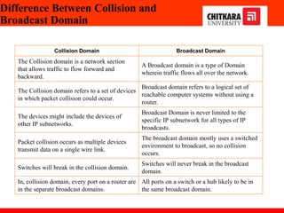
Introduction of Computer
Networks
Department of Computer Science and Engineering,
Chitkara University, Punjab
Prepared by
Dr. Chetna(CSE)
Index
1. Network affects our lives
2. Network Components
3. Types of Computer Networks
4. Network Topologies
5. Collision Domain
6. Broadcast Domain
7. Recent Network Trends and Network security
Networks affect our Lives
1 Networks Connect Us
In today’s world, through the use of networks, we are connected like never
before. People with ideas can communicate instantly with others to make those
ideas a reality. News events and discoveries are known worldwide in seconds.
Individuals can even connect and play games with friends separated by oceans
and continents
2 No Boundaries
The creation of online communities for the exchange of ideas and information
has the potential to increase productivity opportunities across the globe. The
creation of the cloud lets us store documents and pictures and access them
anywhere, anytime. So whether we are on a train, in a park, or standing on top
of a mountain, we can seamlessly access our data and applications on any
device.
Network Components
End Devices : PC, Laptop, Mobile
Connecting Devices: Hubs, Switches, Routers
Transmission Media: Wired, Wireless Media
Software: Operating Systems for PCs and Connecting Devices
Figure 1 Shows the network components in detail.
Network Components
1 Host
To be a part of a global online community, your computer, tablet, or smartphone must first be
connected to a network. That network must be connected to the internet. This topic discusses the
parts of a network.
Host: All computers that are connected to a network and participate directly in network
communication are classified as hosts. Hosts can be called end devices. Some hosts are also called
clients. However, the term hosts specifically refers to devices on the network that are assigned a
number for communication purposes. This number identifies the host within a particular network.
IP: This number is called the Internet Protocol (IP) address. An IP address identifies the host and
the network to which the host is attached.
Server: Servers are computers with software that allow them to provide information, like email or
web pages, to other end devices on the network. Each service requires separate server software. For
example, a server requires web server software to provide web services to the network. A computer
with server software can provide services simultaneously to many different clients.
As mentioned, clients are a type of host. Clients have software for requesting and displaying the
information obtained from the server, as shown in the figure.
Figure 2 Illustrates the Client as host and communicating with the Server.
Network Components
2 Peer-to-Peer
Client and server software usually run on separate computers, but it is also possible for one computer to
be used for both roles at the same time. In small businesses and homes, many computers function as the
servers and clients on the network. This type of network is called a peer-to-peer network.
In the figure, the print-sharing PC has a Universal Serial Bus (USB) connection to the printer and a
network connection, using a network interface card (NIC), to the file-sharing PC.
Advantages Disadvantages
Easy to set up No centralized administration
Less complex Not a secure
Lower cost as network devices and
dedicated servers are not essential
Not scalable
Used for a simple task like transfer files
and sharing printers
All devices may act as both clients and servers
which can slow their performance.
Figure 3 Shows the peer-to-peer communication.
Table 1 Shows the advantages and disadvantages of a Peer-to-Peer setup.
Network Components
3 End devices
The network devices that people are most familiar with are end devices. To distinguish one end
device from another, each end device on a network has an address. When an end device initiates
communication, it uses the address of the destination end device to specify where to deliver the
message. An end device is either the source or destination of a message transmitted over the
network.
Figure 4 shows end devices communication
Data originates from the end device, flows through the network, and reaches an end device.
LAN
End device
End device
Internetwork
LAN
Network Components
4 Intermediary devices
Intermediary devices connect the individual end devices to the network. They can connect multiple
individual networks to form an internetwork. These intermediary devices provide connectivity and
ensure that data flows across the network. Intermediary devices use the destination end device
address, in conjunction with information about the network interconnections, to determine the path
that messages should take through the network. Examples of the more common intermediary
devices and a list of functions are shown in the figure.
Functions: Regenerates and retransmits communication signals, Maintain information about
what pathways exist through the network and internetwork, Notify other devices of errors and
communication failures, Direct data along alternate pathways when there is a link failure, Classify
and direct messages according to priorities, Permit or deny the flow of data, based on security
settings
Note: The ethernet hub is known as a multiport repeater. Repeater Regenerates and retransmits
communication signals. Notice all intermediary devices perform the function of a repeater.
Figure 5 Shows the Intermediary devices used in the network.
Network Components
5 Network Media
Communication transmits across a network of media. The media provides the channel over which the
message travels from source to destination. Modern networks primarily use three types of media to
interconnect devices, as shown in the figure:
• Metal wires within cables - Data is encoded into electrical impulses.
• Glass or plastic fibers within cables (fiber-optic cable) - Data is encoded into pulses of light.
• Wireless transmission - Data is encoded via modulation of specific frequencies of
electromagnetic waves.
Criteria for choosing: max. distance, environment, amount of data, cost of media, and installation.
Figure 6 Various ways of communication transmit across a network of
media.
Network representation
In addition to these network components, specialized terminology is used to describe
how each of these devices and media connect:
•Network Interface Card (NIC) - A NIC physically connects the end device to the
network.
•Physical Port - A connector or outlet on a networking device where the media
connects to an end device or another networking device.
•Interface - Specialized ports on a networking device that connect to individual
networks. Because routers connect networks, the ports on a router are referred to as
network interfaces.
Note: The terms port and interface are often used interchangeably.
The classification of networks in computers can
be done according to their
i)Size: expressed by the
geographic area and number of computers
ii)Purpose: devices housed in a single room to
millions of devices spread across the world.
Different Types of Computer
Networks
Figure 7 Generic computer network
connections
Types of Computer Networks
Figure 8 Types of computer networks
Personal Area Network
PAN (Personal Area Network) is a
computer network formed around
a person.
Characteristics of PAN
Below are the main characteristics of
PAN:
•It is mostly personal devices network
equipped within a limited area.
•Appliances use for PAN: cordless
mice, keyboards, and Bluetooth
systems.
Figure 9 Shows some of the PAN (Personal Area Network) appliances
Local Area Network
A group of computer and peripheral
devices which are connected in a
limited area such as school,
laboratory, home, and office
building.
The simplest type of LAN network
is to connect computers and a printer
in someone’s home or office.
Figure 10 The simplest type of LAN network
Characteristics of LAN
Here are the important
characteristics of a LAN
network:
•It is a private network, so an
outside regulatory body never
controls it.
•LAN operates at a relatively
higher speed compared to other
WAN systems.
Local Area Network
Figure 11 Generic workflow of the simplest type of LAN network
Advantages and Disadvantages of LAN
WAN:Wide Area Network
WAN is another important computer network that which is
spread across a large geographical area.
Figure 12 The simplest type of WAN network
Intranets and Extranets
Two other terms are similar to the term internet: intranet and extranet.
Intranet: It is a term often used to refer to a private connection of LANs and
WANs that belong to an organization. An intranet is designed to be accessible
only by the organization's members, employees, or others with authorization.
Extranet: An organization may use an extranet to provide secure and safe access
to individuals who work for a different organization but require access to the
organization’s data. Here are some examples of extranets:
A company that is providing access to outside suppliers and contractors
A hospital that is providing a booking system to doctors so they can make
appointments for their patients
A local office of education that provides budget and personnel information to the
schools in its district
Intranets and Extranets
The figure illustrates the levels of access that different groups have to a company intranet, a company
extranet, and the internet.
A center circle is labeled Intranet and has company-only access. Surrounding that is another circle labeled
Extranet which is accessible by suppliers, customers, and collaborators. Surrounding that is another circle
labeled the Internet which is accessible by the world.
Figure 13 illustrates the levels of access that different groups have to a company intranet, a company
extranet, and the internet
Topologies
The Physical or Logical layout of a network is known as
Topology of the network.
It can be divided into:
i) Physical Topology
ii)Logical Topology
Figure 14 Various network Topology’s.
Topologies
Figure 15 Illustrates logical topology.
Topologies
This example shows the department server, one admin, various classroom that are connected to each other
by routers, ethernet, internet and various addresses. This depict the way data is accessed and transmit
packets is example of logical topology.
Mesh Topology
In a mesh topology, every device is connected to
another device via a particular channel.
Every device is connected with another via
dedicated channels. These channels are known as
links.
Figure 16 Illustrates Mesh topology.
•Suppose, N number of devices are connected with
each other in a mesh topology, the total number of
ports that are required by each device is N-1.
•In Figure 1, there are 5 devices connected to each
other, hence the total number of ports required by
each device is 4. Total number of ports
required=N*(N-1).
•Suppose, N number of devices are connected with
each other in a mesh topology, then the total number
of dedicated links required to connect them is NC2 i.e.
N(N-1)/2. In Figure 1, there are 5 devices connected
to each other, hence the total number of links
required is 5*4/2 = 10.
Mesh Topology
Figure 17 Mesh topology with 5 computers connections.
In star topology, all the devices are connected to a single networking device through a
cable. This central device may be hub, switch, router and all other nodes are
connected to the central node.
Star Topology
Figure 18 Star topology, Hub at centre and rest all are PC’s
Advantages of this topology :
•If N devices are connected in a star topology, then
the number of cables required to connect them is N.
So, it is easy to set up.
•Each device requires only 1 port i.e. to connect to the
hub, therefore the total number of ports required is N.
Problems with this topology :
•If the concentrator (hub) on which the whole
topology relies fails, the whole system will crash
down.
•The cost of installation is high.
•Performance is based on the single concentrator i.e.
hub.
Star Topology
Figure 19 Workflow of Star topology
Bus Topology
Bus topology is a network type in which every computer and network device is
connected to a single cable. It transmits the data from one end to another in a single
direction. No bi-directional feature is in bus topology.
Figure 20 Workflow of Bus topology
Advantages of this topology :
•If N devices are connected in a bus topology,
then the number of cables required to connect
them is 1, which is known as backbone cable,
and N drop lines are required.
•The cost of the cable is less as compared to
other topologies, but it is used to build small
networks.
Problems with this topology :
•If the common cable fails, then the whole
system will crash down.
•If the network traffic is heavy, it increases
collisions in the network. To avoid this, various
protocols are used in the MAC layer known as
Pure Aloha, Slotted Aloha, CSMA/CD, etc.
•Security is very low.
Bus Topology
Figure 21 Bus topology connection.
Ring Topology
In this topology, it forms a ring connecting
devices with exactly two neighboring devices.
Several repeaters are used for Ring topology
with a large number of nodes, because if
someone wants to send some data to the last
node in the ring topology with 100 nodes, then
the data will have to pass through 99 nodes to
reach the 100th node. Hence to prevent data loss
repeaters are used in the network.
The transmission is unidirectional, but it can be
made bidirectional by having 2 connections
between each Network Node, it is called Dual
Ring Topology.
Figure 22 Flow of message in Ring topology.
The following operations take place in ring
topology are :
1.One station is known as a monitor station
which takes all the responsibility to perform the
operations.
2.To transmit the data, the station has to hold the
token. After the transmission is done, the token
is to be released for other stations to use.
3.When no station is transmitting the data, then
the token will circulate in the ring.
4.There are two types of token release
techniques: Early token release releases the
token just after transmitting the data and Delay
token release releases the token after the
acknowledgment is received from the receiver.
Ring Topology
Figure 23 Operations in Ring topology.
Advantages of this topology :
•The possibility of collision is minimum in
this type of topology.
•Cheap to install and expand.
Problems with this topology :
•Troubleshooting is difficult in this topology.
•The addition of stations in between or
removal of stations can disturb the whole
topology.
•Less secure.
Ring Topology
Figure 24 Operations in Ring topology.
Tree Topology
This topology is the variation of Star topology. This topology has a hierarchical
flow of data.
Figure 25 Shows Tree topology’s hierarchical flow of data.
In this, the various secondary hubs are connected to the central hub which contains
the repeater. In this data flow from top to bottom i.e. from the central hub to
secondary and then to the devices or from bottom to top i.e. devices to the
secondary hub and then to the central hub.
Tree Topology
Figure 26 Tree topology connected to the central and secondary hub.
Tree Topology
Figure 27 Tree topology with specific addresses.
Topology
Advantages of this topology :
•It allows more devices to be attached to a single central hub thus it decreases the
distance that is traveled by the signal to come to the devices.
•It allows the network to get isolated and also prioritize from different computers.
Problems with this topology :
•If the central hub gets fails the entire system fails.
•The cost is high because of cabling.
What is Domain?
• A domain is a type of computer network in which all user computers,
printer accounts, and other devices are registered.
• It is a central database located on single or multiple clusters of central
computers, that is known as domain controllers.
Figure 28 Shows types of Domain
Collision Domain
• Collisions will happen in an Ethernet Network when two devices simultaneously try to send
data on the Shared Media, since Shared Media is half-duplex and sending and receiving are not
supported at the same time.
• Collisions are a normal part of life in an Ethernet network when Ethernet operates in a Half-
duplex and under most circumstances should not be considered a problem.
• A Collision Domain is any network segment in which collisions can happen (usually in
Ethernet networks). In other words, a Collision Domain consists of all the devices connected
using a Shared Media (Bus Topolgy or using Ethernet Hubs) where a Collision can happen
between any device at any time.
Figure 29 Shows collision domain in detail with connection.
Broadcast Domain
• Broadcast is a type of communication, where the sending device send a single
copy of data and that copy of data will be delivered to every device in the network
segment. Broadcast is a required type of communication and we cannot avoid
Broadcasts, because many protocols (Example: ARP and DHCP) and applications
are dependent on Broadcast to function.
• A Broadcast Domain consists of all the devices that will receive any broadcast
packet originating from any device within the network segment.
• In Mention picture, "Computer A" is sending a broadcast and switch will forward it
to every ports and all the switchs will get a copy of broadcast packet. Every
switch will flood the broadcast packet to all the ports. Router also will get a copy
of broadcast packet, but the Router will not forward the packet to the next
network segment.
• As the number of devices in the Broadcast Domain increases, number of
Broadcasts also increases and the quality of the network will come down.
Figure 30 Shows broadcast domain in detail with the connection.
Difference Between Collision and
Broadcast Domain
Collision Domain Broadcast Domain
The Collision domain is a network section
that allows traffic to flow forward and
backward.
A Broadcast domain is a type of Domain
wherein traffic flows all over the network.
The Collision domain refers to a set of devices
in which packet collision could occur.
Broadcast domain refers to a logical set of
reachable computer systems without using a
router.
The devices might include the devices of
other IP subnetworks.
Broadcast Domain is never limited to the
specific IP subnetwork for all types of IP
broadcasts.
Packet collision occurs as multiple devices
transmit data on a single wire link.
The broadcast domain mostly uses a switched
environment to broadcast, so no collision
occurs.
Switches will break in the collision domain.
Switches will never break in the broadcast
domain.
In, collision domain, every port on a router are
in the separate broadcast domains.
All ports on a switch or a hub likely to be in
the same broadcast domain.
Recent Network Trends
Several networking trends affect organizations and consumers:
• Bring Your Own Device (BYOD): BYOD enables end users the freedom to use personal tools to
access information and communicate across a business or campus network. These include laptops,
notebooks, tablets, smartphones, and e-readers. These may be purchased by the company or school,
purchased by the individual, or both.
• Online collaboration: Collaboration is defined as “the act of working with another or others on a joint
project.” Collaboration tools, like Cisco WebEx give employees, students, teachers, customers, and
partners a way to instantly connect, interact, and achieve their objectives. Collaboration is also a
priority in education. Students need to collaborate to assist each other in learning, to develop the team
skills used in the workforce, and work together on team-based projects.
• Video communications: Video conferencing is a powerful tool for communicating with others, both
locally and globally. Video is becoming a critical requirement for effective collaboration as
organizations extend across geographic and cultural boundaries.
• Cloud Computing: Cloud computing is one of the ways that we access and store data. Cloud
computing allows us to store personal files, even backup an entire drive on servers over the internet.
Applications such as word processing and photo editing can be accessed using the cloud.
Network security:
Network security is an integral part of computer networking. Some common security threats are
Viruses, worms, Trojan horses, Spyware and adware, Zero-day attacks, Threat actor attacks, Denial of
service attacks, Identity theft, etc. Further, security solutions can be Antivirus and antispyware,
Firewall filtering, etc.
Cisco Packet Tracer
Cisco packet Tracer
Simulation, Visualization, Collaboration
collaborate on multiuser activities
simulate IOS commands
visualize network traffic
Supports Homework and Pre-Lab Prep
Questions
1.During a routine inspection, a technician discovered that software that was installed on a computer was secretly
collecting data about websites that were visited by users of the computer. Which type of threat is affecting this
computer?
identity theft
spyware
zero-day attack
DoS attack​
2.Which term refers to a network that provides secure access to the corporate offices by suppliers, customers and
collaborators?
Internet
extranet
extendednet
Intranet
3.A large corporation has modified its network to allow users to access network resources from their personal
laptops and smart phones. Which networking trend does this describe?
bring your own device
video conferencing
cloud computing
online collaboration
Questions
4.What is an ISP?
It is a standards body that develops cabling and wiring standards for networking.
It is a networking device that combines the functionality of several different networking devices in one.
It is a protocol that establishes how computers within a local network communicate.
It is an organization that enables individuals and businesses to connect to the Internet.
5.In which scenario would the use of a WISP be recommended?
an Internet cafe in a city
a farm in a rural area without wired broadband access
an apartment in a building with cable access to the Internet
any home with multiple wireless devices
Computer Networks Dr. Vidhu Baggan

Computer Networking Notes Second Year Btech Engeeneering.pptx

  • 1.
    Introduction of Computer Networks Departmentof Computer Science and Engineering, Chitkara University, Punjab Prepared by Dr. Chetna(CSE)
  • 2.
    Index 1. Network affectsour lives 2. Network Components 3. Types of Computer Networks 4. Network Topologies 5. Collision Domain 6. Broadcast Domain 7. Recent Network Trends and Network security
  • 3.
    Networks affect ourLives 1 Networks Connect Us In today’s world, through the use of networks, we are connected like never before. People with ideas can communicate instantly with others to make those ideas a reality. News events and discoveries are known worldwide in seconds. Individuals can even connect and play games with friends separated by oceans and continents 2 No Boundaries The creation of online communities for the exchange of ideas and information has the potential to increase productivity opportunities across the globe. The creation of the cloud lets us store documents and pictures and access them anywhere, anytime. So whether we are on a train, in a park, or standing on top of a mountain, we can seamlessly access our data and applications on any device.
  • 4.
    Network Components End Devices: PC, Laptop, Mobile Connecting Devices: Hubs, Switches, Routers Transmission Media: Wired, Wireless Media Software: Operating Systems for PCs and Connecting Devices Figure 1 Shows the network components in detail.
  • 5.
    Network Components 1 Host Tobe a part of a global online community, your computer, tablet, or smartphone must first be connected to a network. That network must be connected to the internet. This topic discusses the parts of a network. Host: All computers that are connected to a network and participate directly in network communication are classified as hosts. Hosts can be called end devices. Some hosts are also called clients. However, the term hosts specifically refers to devices on the network that are assigned a number for communication purposes. This number identifies the host within a particular network. IP: This number is called the Internet Protocol (IP) address. An IP address identifies the host and the network to which the host is attached. Server: Servers are computers with software that allow them to provide information, like email or web pages, to other end devices on the network. Each service requires separate server software. For example, a server requires web server software to provide web services to the network. A computer with server software can provide services simultaneously to many different clients. As mentioned, clients are a type of host. Clients have software for requesting and displaying the information obtained from the server, as shown in the figure. Figure 2 Illustrates the Client as host and communicating with the Server.
  • 6.
    Network Components 2 Peer-to-Peer Clientand server software usually run on separate computers, but it is also possible for one computer to be used for both roles at the same time. In small businesses and homes, many computers function as the servers and clients on the network. This type of network is called a peer-to-peer network. In the figure, the print-sharing PC has a Universal Serial Bus (USB) connection to the printer and a network connection, using a network interface card (NIC), to the file-sharing PC. Advantages Disadvantages Easy to set up No centralized administration Less complex Not a secure Lower cost as network devices and dedicated servers are not essential Not scalable Used for a simple task like transfer files and sharing printers All devices may act as both clients and servers which can slow their performance. Figure 3 Shows the peer-to-peer communication. Table 1 Shows the advantages and disadvantages of a Peer-to-Peer setup.
  • 7.
    Network Components 3 Enddevices The network devices that people are most familiar with are end devices. To distinguish one end device from another, each end device on a network has an address. When an end device initiates communication, it uses the address of the destination end device to specify where to deliver the message. An end device is either the source or destination of a message transmitted over the network. Figure 4 shows end devices communication Data originates from the end device, flows through the network, and reaches an end device. LAN End device End device Internetwork LAN
  • 8.
    Network Components 4 Intermediarydevices Intermediary devices connect the individual end devices to the network. They can connect multiple individual networks to form an internetwork. These intermediary devices provide connectivity and ensure that data flows across the network. Intermediary devices use the destination end device address, in conjunction with information about the network interconnections, to determine the path that messages should take through the network. Examples of the more common intermediary devices and a list of functions are shown in the figure. Functions: Regenerates and retransmits communication signals, Maintain information about what pathways exist through the network and internetwork, Notify other devices of errors and communication failures, Direct data along alternate pathways when there is a link failure, Classify and direct messages according to priorities, Permit or deny the flow of data, based on security settings Note: The ethernet hub is known as a multiport repeater. Repeater Regenerates and retransmits communication signals. Notice all intermediary devices perform the function of a repeater. Figure 5 Shows the Intermediary devices used in the network.
  • 9.
    Network Components 5 NetworkMedia Communication transmits across a network of media. The media provides the channel over which the message travels from source to destination. Modern networks primarily use three types of media to interconnect devices, as shown in the figure: • Metal wires within cables - Data is encoded into electrical impulses. • Glass or plastic fibers within cables (fiber-optic cable) - Data is encoded into pulses of light. • Wireless transmission - Data is encoded via modulation of specific frequencies of electromagnetic waves. Criteria for choosing: max. distance, environment, amount of data, cost of media, and installation. Figure 6 Various ways of communication transmit across a network of media.
  • 10.
    Network representation In additionto these network components, specialized terminology is used to describe how each of these devices and media connect: •Network Interface Card (NIC) - A NIC physically connects the end device to the network. •Physical Port - A connector or outlet on a networking device where the media connects to an end device or another networking device. •Interface - Specialized ports on a networking device that connect to individual networks. Because routers connect networks, the ports on a router are referred to as network interfaces. Note: The terms port and interface are often used interchangeably.
  • 11.
    The classification ofnetworks in computers can be done according to their i)Size: expressed by the geographic area and number of computers ii)Purpose: devices housed in a single room to millions of devices spread across the world. Different Types of Computer Networks Figure 7 Generic computer network connections
  • 12.
    Types of ComputerNetworks Figure 8 Types of computer networks
  • 13.
    Personal Area Network PAN(Personal Area Network) is a computer network formed around a person. Characteristics of PAN Below are the main characteristics of PAN: •It is mostly personal devices network equipped within a limited area. •Appliances use for PAN: cordless mice, keyboards, and Bluetooth systems. Figure 9 Shows some of the PAN (Personal Area Network) appliances
  • 14.
    Local Area Network Agroup of computer and peripheral devices which are connected in a limited area such as school, laboratory, home, and office building. The simplest type of LAN network is to connect computers and a printer in someone’s home or office. Figure 10 The simplest type of LAN network
  • 15.
    Characteristics of LAN Hereare the important characteristics of a LAN network: •It is a private network, so an outside regulatory body never controls it. •LAN operates at a relatively higher speed compared to other WAN systems. Local Area Network Figure 11 Generic workflow of the simplest type of LAN network
  • 16.
  • 17.
    WAN:Wide Area Network WANis another important computer network that which is spread across a large geographical area. Figure 12 The simplest type of WAN network
  • 18.
    Intranets and Extranets Twoother terms are similar to the term internet: intranet and extranet. Intranet: It is a term often used to refer to a private connection of LANs and WANs that belong to an organization. An intranet is designed to be accessible only by the organization's members, employees, or others with authorization. Extranet: An organization may use an extranet to provide secure and safe access to individuals who work for a different organization but require access to the organization’s data. Here are some examples of extranets: A company that is providing access to outside suppliers and contractors A hospital that is providing a booking system to doctors so they can make appointments for their patients A local office of education that provides budget and personnel information to the schools in its district
  • 19.
    Intranets and Extranets Thefigure illustrates the levels of access that different groups have to a company intranet, a company extranet, and the internet. A center circle is labeled Intranet and has company-only access. Surrounding that is another circle labeled Extranet which is accessible by suppliers, customers, and collaborators. Surrounding that is another circle labeled the Internet which is accessible by the world. Figure 13 illustrates the levels of access that different groups have to a company intranet, a company extranet, and the internet
  • 20.
    Topologies The Physical orLogical layout of a network is known as Topology of the network. It can be divided into: i) Physical Topology ii)Logical Topology Figure 14 Various network Topology’s.
  • 21.
  • 22.
    Figure 15 Illustrateslogical topology. Topologies This example shows the department server, one admin, various classroom that are connected to each other by routers, ethernet, internet and various addresses. This depict the way data is accessed and transmit packets is example of logical topology.
  • 23.
    Mesh Topology In amesh topology, every device is connected to another device via a particular channel. Every device is connected with another via dedicated channels. These channels are known as links. Figure 16 Illustrates Mesh topology.
  • 24.
    •Suppose, N numberof devices are connected with each other in a mesh topology, the total number of ports that are required by each device is N-1. •In Figure 1, there are 5 devices connected to each other, hence the total number of ports required by each device is 4. Total number of ports required=N*(N-1). •Suppose, N number of devices are connected with each other in a mesh topology, then the total number of dedicated links required to connect them is NC2 i.e. N(N-1)/2. In Figure 1, there are 5 devices connected to each other, hence the total number of links required is 5*4/2 = 10. Mesh Topology Figure 17 Mesh topology with 5 computers connections.
  • 25.
    In star topology,all the devices are connected to a single networking device through a cable. This central device may be hub, switch, router and all other nodes are connected to the central node. Star Topology Figure 18 Star topology, Hub at centre and rest all are PC’s
  • 26.
    Advantages of thistopology : •If N devices are connected in a star topology, then the number of cables required to connect them is N. So, it is easy to set up. •Each device requires only 1 port i.e. to connect to the hub, therefore the total number of ports required is N. Problems with this topology : •If the concentrator (hub) on which the whole topology relies fails, the whole system will crash down. •The cost of installation is high. •Performance is based on the single concentrator i.e. hub. Star Topology Figure 19 Workflow of Star topology
  • 27.
    Bus Topology Bus topologyis a network type in which every computer and network device is connected to a single cable. It transmits the data from one end to another in a single direction. No bi-directional feature is in bus topology. Figure 20 Workflow of Bus topology
  • 28.
    Advantages of thistopology : •If N devices are connected in a bus topology, then the number of cables required to connect them is 1, which is known as backbone cable, and N drop lines are required. •The cost of the cable is less as compared to other topologies, but it is used to build small networks. Problems with this topology : •If the common cable fails, then the whole system will crash down. •If the network traffic is heavy, it increases collisions in the network. To avoid this, various protocols are used in the MAC layer known as Pure Aloha, Slotted Aloha, CSMA/CD, etc. •Security is very low. Bus Topology Figure 21 Bus topology connection.
  • 29.
    Ring Topology In thistopology, it forms a ring connecting devices with exactly two neighboring devices. Several repeaters are used for Ring topology with a large number of nodes, because if someone wants to send some data to the last node in the ring topology with 100 nodes, then the data will have to pass through 99 nodes to reach the 100th node. Hence to prevent data loss repeaters are used in the network. The transmission is unidirectional, but it can be made bidirectional by having 2 connections between each Network Node, it is called Dual Ring Topology. Figure 22 Flow of message in Ring topology.
  • 30.
    The following operationstake place in ring topology are : 1.One station is known as a monitor station which takes all the responsibility to perform the operations. 2.To transmit the data, the station has to hold the token. After the transmission is done, the token is to be released for other stations to use. 3.When no station is transmitting the data, then the token will circulate in the ring. 4.There are two types of token release techniques: Early token release releases the token just after transmitting the data and Delay token release releases the token after the acknowledgment is received from the receiver. Ring Topology Figure 23 Operations in Ring topology.
  • 31.
    Advantages of thistopology : •The possibility of collision is minimum in this type of topology. •Cheap to install and expand. Problems with this topology : •Troubleshooting is difficult in this topology. •The addition of stations in between or removal of stations can disturb the whole topology. •Less secure. Ring Topology Figure 24 Operations in Ring topology.
  • 32.
    Tree Topology This topologyis the variation of Star topology. This topology has a hierarchical flow of data. Figure 25 Shows Tree topology’s hierarchical flow of data.
  • 33.
    In this, thevarious secondary hubs are connected to the central hub which contains the repeater. In this data flow from top to bottom i.e. from the central hub to secondary and then to the devices or from bottom to top i.e. devices to the secondary hub and then to the central hub. Tree Topology Figure 26 Tree topology connected to the central and secondary hub.
  • 34.
    Tree Topology Figure 27Tree topology with specific addresses.
  • 35.
    Topology Advantages of thistopology : •It allows more devices to be attached to a single central hub thus it decreases the distance that is traveled by the signal to come to the devices. •It allows the network to get isolated and also prioritize from different computers. Problems with this topology : •If the central hub gets fails the entire system fails. •The cost is high because of cabling.
  • 36.
    What is Domain? •A domain is a type of computer network in which all user computers, printer accounts, and other devices are registered. • It is a central database located on single or multiple clusters of central computers, that is known as domain controllers. Figure 28 Shows types of Domain
  • 37.
    Collision Domain • Collisionswill happen in an Ethernet Network when two devices simultaneously try to send data on the Shared Media, since Shared Media is half-duplex and sending and receiving are not supported at the same time. • Collisions are a normal part of life in an Ethernet network when Ethernet operates in a Half- duplex and under most circumstances should not be considered a problem. • A Collision Domain is any network segment in which collisions can happen (usually in Ethernet networks). In other words, a Collision Domain consists of all the devices connected using a Shared Media (Bus Topolgy or using Ethernet Hubs) where a Collision can happen between any device at any time. Figure 29 Shows collision domain in detail with connection.
  • 38.
    Broadcast Domain • Broadcastis a type of communication, where the sending device send a single copy of data and that copy of data will be delivered to every device in the network segment. Broadcast is a required type of communication and we cannot avoid Broadcasts, because many protocols (Example: ARP and DHCP) and applications are dependent on Broadcast to function. • A Broadcast Domain consists of all the devices that will receive any broadcast packet originating from any device within the network segment. • In Mention picture, "Computer A" is sending a broadcast and switch will forward it to every ports and all the switchs will get a copy of broadcast packet. Every switch will flood the broadcast packet to all the ports. Router also will get a copy of broadcast packet, but the Router will not forward the packet to the next network segment. • As the number of devices in the Broadcast Domain increases, number of Broadcasts also increases and the quality of the network will come down. Figure 30 Shows broadcast domain in detail with the connection.
  • 39.
    Difference Between Collisionand Broadcast Domain Collision Domain Broadcast Domain The Collision domain is a network section that allows traffic to flow forward and backward. A Broadcast domain is a type of Domain wherein traffic flows all over the network. The Collision domain refers to a set of devices in which packet collision could occur. Broadcast domain refers to a logical set of reachable computer systems without using a router. The devices might include the devices of other IP subnetworks. Broadcast Domain is never limited to the specific IP subnetwork for all types of IP broadcasts. Packet collision occurs as multiple devices transmit data on a single wire link. The broadcast domain mostly uses a switched environment to broadcast, so no collision occurs. Switches will break in the collision domain. Switches will never break in the broadcast domain. In, collision domain, every port on a router are in the separate broadcast domains. All ports on a switch or a hub likely to be in the same broadcast domain.
  • 40.
    Recent Network Trends Severalnetworking trends affect organizations and consumers: • Bring Your Own Device (BYOD): BYOD enables end users the freedom to use personal tools to access information and communicate across a business or campus network. These include laptops, notebooks, tablets, smartphones, and e-readers. These may be purchased by the company or school, purchased by the individual, or both. • Online collaboration: Collaboration is defined as “the act of working with another or others on a joint project.” Collaboration tools, like Cisco WebEx give employees, students, teachers, customers, and partners a way to instantly connect, interact, and achieve their objectives. Collaboration is also a priority in education. Students need to collaborate to assist each other in learning, to develop the team skills used in the workforce, and work together on team-based projects. • Video communications: Video conferencing is a powerful tool for communicating with others, both locally and globally. Video is becoming a critical requirement for effective collaboration as organizations extend across geographic and cultural boundaries. • Cloud Computing: Cloud computing is one of the ways that we access and store data. Cloud computing allows us to store personal files, even backup an entire drive on servers over the internet. Applications such as word processing and photo editing can be accessed using the cloud. Network security: Network security is an integral part of computer networking. Some common security threats are Viruses, worms, Trojan horses, Spyware and adware, Zero-day attacks, Threat actor attacks, Denial of service attacks, Identity theft, etc. Further, security solutions can be Antivirus and antispyware, Firewall filtering, etc.
  • 41.
  • 42.
  • 43.
    Simulation, Visualization, Collaboration collaborateon multiuser activities simulate IOS commands visualize network traffic
  • 44.
  • 45.
    Questions 1.During a routineinspection, a technician discovered that software that was installed on a computer was secretly collecting data about websites that were visited by users of the computer. Which type of threat is affecting this computer? identity theft spyware zero-day attack DoS attack​ 2.Which term refers to a network that provides secure access to the corporate offices by suppliers, customers and collaborators? Internet extranet extendednet Intranet 3.A large corporation has modified its network to allow users to access network resources from their personal laptops and smart phones. Which networking trend does this describe? bring your own device video conferencing cloud computing online collaboration
  • 46.
    Questions 4.What is anISP? It is a standards body that develops cabling and wiring standards for networking. It is a networking device that combines the functionality of several different networking devices in one. It is a protocol that establishes how computers within a local network communicate. It is an organization that enables individuals and businesses to connect to the Internet. 5.In which scenario would the use of a WISP be recommended? an Internet cafe in a city a farm in a rural area without wired broadband access an apartment in a building with cable access to the Internet any home with multiple wireless devices
  • 47.