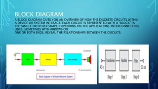
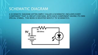
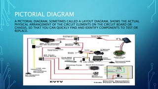
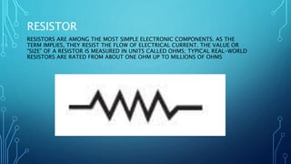
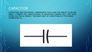
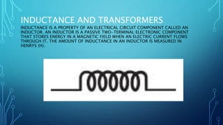
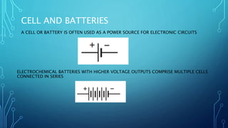
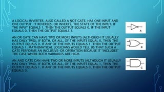
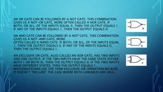
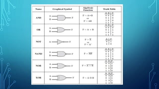
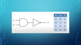
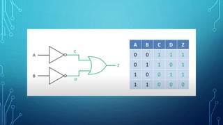
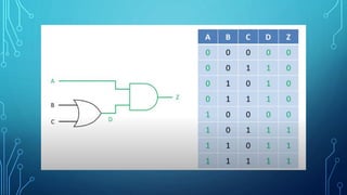
This document discusses different types of diagrams used to represent electronic circuits and components. It describes block diagrams that show how discrete circuits interact in a device or system. It also describes schematic diagrams that include every component in a circuit using unique symbols, and pictorial diagrams that show the physical layout of components. It provides symbols for common electronic components like resistors, capacitors, inductors, switches, diodes, and batteries. It explains logic gates like inverters, AND gates, OR gates, NAND gates, NOR gates, and XOR gates that are used in digital electronics.


![[Deck] What's New in Spark-Iceberg Integration via DSV2.pptx](https://cdn.slidesharecdn.com/ss_thumbnails/deckwhatsnewinspark-icebergintegrationviadsv2-260210005337-25955b12-thumbnail.jpg?width=640&height=640&fit=bounds)


