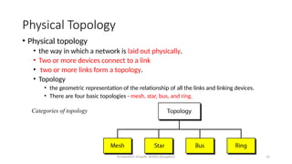
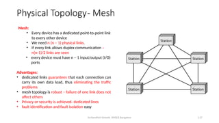
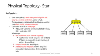
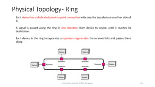
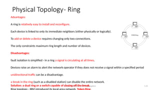
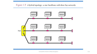
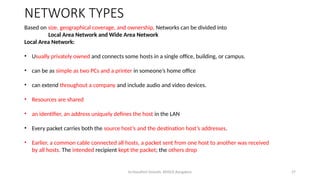
1
COMPUTER NETWORKS
22CS4PCCON
Dr.Nandhini Vineeth, BMSCE,Bangalore
UNIT I
Dr.Nandhini Vineeth, BMSCE,Bangalore 2
Data Communication
• Communication
• Sharing of information
• local (face to face) or remote (telecommunication:tele-far)
• Telecommunication- telephony, telegraphy, television
• Data – communicated information
• Data communications are the exchange of data between two devices via
some form of transmission medium such as a wire cable.
Dr.Nandhini Vineeth, BMSCE,Bangalore 3
Data Communication
The effectiveness of a data communications system depends on four fundamental characteristics: delivery, accuracy,
timeliness, and jitter.
1. Delivery.
• Data to be delivered to correct destination and correct user
2. Accuracy.
• Data is to be delivered accurately.
• If altered in transmission and left uncorrected become unusable.
• Ex. Text transfers- Email, numerical transfers say amount transferred from one account to another
3. Timeliness.
• Data need to be delivered in a timely manner.
• Real-time transmission – Data becomes useless when it arrives late Ex. Audio and video
4. Jitter.
• Jitter refers to the variation in the packet arrival time.
• An uneven delay is experienced in the delivery of audio or video packets. Some may arrive in say 10 ms and some in 20 ms.
Dr.Nandhini Vineeth, BMSCE,Bangalore 4
Data Communication-Components
• A data communications system has five components
1. Message:
• the information (data) to be communicated.
• Forms: include text, numbers, pictures, audio, and video.
2. Sender:
• The device that sends the data message.
• Ex. computer, workstation, telephone handset, video camera, and so on.
3. Receiver:
• The device that receives the message.
• Ex., computer, workstation, telephone handset, television, and so on.
4. Transmission medium:
• the physical path by which a message travels from sender to receiver.
• Ex. twisted-pair wire, coaxial cable, fiber-optic cable, and radio waves.
5. Protocol:
• A protocol is a set of rules that govern data communications.
• It represents an agreement between the communicating devices.
• Without a protocol, two devices may be connected but not communicating
Dr.Nandhini Vineeth, BMSCE,Bangalore 1.5
Figure 1.1 Components of a data communication system
Dr.Nandhini Vineeth, BMSCE,Bangalore 6
Data Communication-Data Representation
• Different forms of data: text, numbers, images, audio, and video.
• Text :
• represented as a bit pattern, a sequence of bits (0s or 1s).
• Different sets of bit patterns to represent text symbols.
• Code- Each set Ex. ASCII – 7 bits, Unicode – 32 bits
• Coding- the process of representing symbols.
• Images
• represented by bit patterns.
• an image is composed of a matrix of pixels (picture elements), where each pixel is a small dot.
• The size of the pixel depends on the resolution.
• Ex., an image can be divided into 1000 pixels (low resolution) or 10,000 pixels (high resolution-
needs more memory)
Dr.Nandhini Vineeth, BMSCE,Bangalore 7
Data Communication-Data Representation
• Images
• Each pixel is assigned a bit pattern. The size and the value of the pattern depend on the image.
• Ex. black and-white dots (e.g., a chessboard), a 1-bit pattern is enough to represent a pixel.
• Gray scale- 2-bit patterns-00 : black pixel, 01- a dark gray pixel, 10- a light gray pixel, 11- white pixel.
• Color images.
• RGB - combination of three primary colors: red, green, and blue.
• The intensity of each color is measured, and a bit pattern is assigned to it.
• YCM- combination of three other primary colors: yellow, cyan, and magenta
• Audio:
• Audio refers to the recording or broadcasting of sound or music.
• Diff: from text, numbers, or images. It is continuous, not discrete.
• Ex, a microphone to change voice or music to an electric signal, we create a continuous signal.
• Video:
• the recording or broadcasting of a picture or movie.
• Video can either be produced as a continuous entity (e.g., by a TV camera), or it can be a combination of images,
each a discrete entity, arranged to convey the idea of motion.
Dr.Nandhini Vineeth, BMSCE,Bangalore 8
Data Communication- Data Flow
• Data Flow Communication between two devices
• can be simplex, half-duplex, or full-duplex
• Simplex:
• the communication is unidirectional, as on a one-way street.
• Only one of the two devices on a link can transmit; the other can only receive
• Ex. Keyboards - only introduce input
• Traditional monitors- only accept output.
• uses the entire capacity of the channel to send data in one direction.
• Half-Duplex:
• each station can both transmit and receive, but not at the same time.
• When one device is sending, the other can only receive, and vice versa
• like a one-lane road with traffic allowed in both directions. When cars are traveling in one
direction, cars going the other way must wait
Dr.Nandhini Vineeth, BMSCE,Bangalore 1.9
Figure 1.2 Data flow (simplex, half-duplex, and full-duplex)
Dr.Nandhini Vineeth, BMSCE,Bangalore 10
Data Communication- Data Flow
• Half-Duplex:
• the entire capacity of a channel is taken over by one of the two devices that is transmitting
• Ex. Walkie-talkies
• Used when there is no need for communication in both directions at the same time
• the entire capacity of the channel can be utilized for each direction.
• Full-Duplex:
• In full-duplex mode (also called duplex), both stations can transmit and receive
• like a two-way street with traffic flowing in both directions at the same time.
• Signals going in one direction share the capacity of the link with signals going in the other direction.
• This sharing can occur in two ways:
• Either the link must contain two physically separate transmission paths, one for sending and the other for receiving;
or
• the capacity of the channel is divided between signals traveling in both directions.
• Ex. One common example of full-duplex communication is the telephone network. When two people are
communicating by a telephone line, both can talk and listen at the same time.
• Used when communication in both directions is required all the time. The capacity of the channel must be divided
between the two directions.
Dr.Nandhini Vineeth, BMSCE,Bangalore 11
1.2 NETWORKS
• A network
• is the interconnection of a set of devices capable of communication.
• a device can be a
• host (end system)
• large computer, desktop, laptop, workstation, cellular phone, or security system.
• connecting device
• router
• connects the network to other networks
• switch
• connects devices together
• modem (modulator-demodulator), which changes the form of data, and so on.
• devices are connected using wired or wireless transmission media such as cable or air.
Dr.Nandhini Vineeth, BMSCE,Bangalore 12
1.2.1 Network Criteria
• The most important of these are performance, reliability, and security.
• Performance
• Performance can be measured in many ways including transit time and response time.
• Transit time
• amount of time required for a message to travel from one device to another.
• Response time
• elapsed time between an inquiry and a response.
• The performance of a network depends on the
• number of users
• type of transmission medium
• capabilities of the connected hardware
• the efficiency of the software
• Performance is often evaluated by two networking metrics: throughput and delay.
• We often need more throughput and less delay.
• In practice, this is very challenging as more data is sent into the network, delay increases.
Dr.Nandhini Vineeth, BMSCE,Bangalore 13
1.2.1 Network Criteria
• Reliability
• Network reliability is measured by
• accuracy of delivery
• the frequency of failure
• the time it takes a link to recover from a failure
• network’s robustness in a disaster/calamity
• Security
• Network security issues include protecting data from
• unauthorized access
• Protecting data from damage and development
• implementing policies and procedures for recovery from breaches and data losses.
Dr.Nandhini Vineeth, BMSCE,Bangalore 14
1.2.2 Physical Structures
• Type of Connection
• Two or more devices are connected through links.
• A link is a communications pathway that transfers data from one device to another.
• For communication to occur, two devices must be connected in some way to the same link at the same
time.
• There are two possible types of connections: point-to-point and multipoint.
• Point-to-Point
• provides a dedicated link between two devices.
• The entire capacity of the link is reserved for transmission between those two devices.
• use an actual length of wire or cable to connect the two ends, but other options, such as microwave or satellite links
• changing television channels by infrared remote control -a point-to-point connection is established
• Multipoint
• A multipoint (also called multidrop) connection is one in which more than two specific devices share a single link
• the capacity of the channel is shared, either spatially or temporally.
• If the link is to be used simultaneously, it is a spatially shared connection.
• If users must take turns, it is a timeshared connection.
Dr.Nandhini Vineeth, BMSCE,Bangalore 1.15
Figure 1.3 Types of connections: point-to-point and multipoint
Dr.Nandhini Vineeth, BMSCE,Bangalore 16
Physical Topology
• Physical topology
• the way in which a network is laid out physically.
• Two or more devices connect to a link
• two or more links form a topology.
• Topology
• the geometric representation of the relationship of all the links and linking devices.
• There are four basic topologies - mesh, star, bus, and ring.
Categories of topology
Dr.Nandhini Vineeth, BMSCE,Bangalore 1.17
Mesh:
• Every device has a dedicated point-to-point link
to every other device
• We need n (n – 1) physical links.
• If every link allows duplex communication –
n(n-1)/2 links are seen
• every device must have n – 1 input/output (I/O)
ports
Advantages:
• dedicated links guarantees that each connection can
carry its own data load, thus eliminating the traffic
problems
• mesh topology is robust – failure of one link does not
affect others
• Privacy or security is achieved- dedicated lines
• fault identification and fault isolation easy
Physical Topology- Mesh
Dr.Nandhini Vineeth, BMSCE,Bangalore 18
• Disadvantages:
• amount of cabling and the number of I/O ports required.
• installation and reconnection are difficult.
• bulk of the wiring can be greater than the available space
• hardware required to connect each link (I/O ports and cable) expensive.
• Hence, implemented in a limited fashion, for example, as a backbone connecting the main computers of a
hybrid network that can include several other topologies.
• One practical example - the connection of telephone regional offices in which each regional office needs to
be connected to every other regional office
Physical Topology- Mesh
Dr.Nandhini Vineeth, BMSCE,Bangalore 19
Star Topology:
• Each device has a dedicated point-to-point link
only to a central controller, called a hub.
• The devices are not directly linked to one another
–no direct traffic between devices.
• Controller acts as an exchange:
• If Device1 wants to communicate to Device2,
D1-> controller->D2
• Advantage:
• less expensive than a mesh topology
• each device needs only one link and one
I/O port to connect it to any number of
others (less cabling)
• easy to install and reconfigure.
• Additions and deletions involve only one
connection: between that device and the
hub.
Physical Topology- Star
Dr.Nandhini Vineeth, BMSCE,Bangalore 20
• Robustness
• if one link fails, only that link is affected.
• All other links remain active, easy fault identification and fault isolation.
• When hub is working, it can be used to monitor link problems and bypass defective links.
• Disadvantage :
• Dependency on one single point, the hub.
• If the hub goes down, the whole system is dead.
• Cabling is better than mesh but inefficient compared to ring or bus
• The star topology is used in local-area networks (LANs)
• High-speed LANs often use a star topology with a central hub.
Physical Topology- Star
Dr.Nandhini Vineeth, BMSCE,Bangalore 1.21
Figure 1.10 An isolated LAN connecting 12 computers to a hub in a closet
Dr.Nandhini Vineeth, BMSCE,Bangalore 1.22
Physical Topology- Bus
• Star and mesh are point to point
• Bus is multipoint
• One long cable acts as a backbone linking all devices in a network
• Nodes are connected to the bus cable by drop lines and taps.
• A drop line is a connection running between the device and the main cable
• A tap is a connector that either splices into the main cable creating a contact with the metallic core
• Limits on the number of taps a bus can support and on the distance between those taps
Dr.Nandhini Vineeth, BMSCE,Bangalore 23
Advantages:
•ease of installation.
•Backbone cable can be laid along the most efficient path and nodes connect to this
•less cabling than mesh or star topologies.
•Used in the design of early local area networks. Traditional Ethernet LANs can use a bus topology
Disadvantages
• include difficult reconnection and fault isolation.
• optimally efficient at installation.
• difficult to add new devices.
• Signal reflection at the taps can cause degradation in quality
can be controlled by limiting the number and spacing of devices connected to a given
length of cable.
Adding new devices may therefore require modification or replacement of the backbone.
A fault or break in the bus cable stops all transmission, even between devices on the same
side of the problem.
The damaged area reflects signals back in the direction of origin, creating noise in both directions.
Physical Topology- Bus
Dr.Nandhini Vineeth, BMSCE,Bangalore 1.24
Each device has a dedicated point-to-point connection with only the two devices on either side of
it.
A signal is passed along the ring in one direction, from device to device, until it reaches its
destination.
Each device in the ring incorporates a repeater- regenerates the received bits and passes them
along
Physical Topology- Ring
Dr.Nandhini Vineeth, BMSCE,Bangalore 1.25
Advantages:
A ring is relatively easy to install and reconfigure.
Each device is linked to only its immediate neighbors (either physically or logically).
To add or delete a device requires changing only two connections.
The only constraints maximum ring length and number of devices.
Disadvantages:
fault isolation is simplified - in a ring a signal is circulating at all times.
Devices raise an alarm to alert the network operator if they does not receive a signal within a specified period
unidirectional traffic can be a disadvantage.
a break in the ring (such as a disabled station) can disable the entire network.
Solution: a dual ring or a switch capable of closing off the break.
Physical Topology- Ring
Dr.Nandhini Vineeth, BMSCE,Bangalore 1.26
Figure 1.9 A hybrid topology: a star backbone with three bus networks
Dr.Nandhini Vineeth, BMSCE,Bangalore 27
NETWORK TYPES
Based on size, geographical coverage, and ownership, Networks can be divided into
Local Area Network and Wide Area Network
Local Area Network:
• Usually privately owned and connects some hosts in a single office, building, or campus.
• can be as simple as two PCs and a printer in someone’s home office
• can extend throughout a company and include audio and video devices.
• Resources are shared
• an identifier, an address uniquely defines the host in the LAN
• Every packet carries both the source host’s and the destination host’s addresses.
• Earlier, a common cable connected all hosts, a packet sent from one host to another was received
by all hosts. The intended recipient kept the packet; the others drop
Dr.Nandhini Vineeth, BMSCE,Bangalore 28
• a smart connecting switch, recognizes the destination address of the packet and guide the packet to
its destination without sending it to all other hosts.
• The switch allows more than one pair to communicate with each other at the same time if there is
no common source and destination among them.
NETWORK TYPES
Dr.Nandhini Vineeth, BMSCE,Bangalore 29
Wide Area Network
• has a wider geographical span, spanning a town, a state, a country, or even the world.
• A LAN interconnects hosts;
• a WAN interconnects connecting devices such as switches, routers, or modems.
• A LAN is normally privately owned by the organization that uses it;
• a WAN is normally created and run by communication companies and leased by an organization that
uses it.
• Two distinct examples of WANs today: point-to-point WANs and switched WANs.
Point-to-Point WAN:
Network that connects two communicating devices through a transmission media (cable or air).
Switched WAN:
• A switched WAN is a network with more than two ends.
• used in the backbone of global communication today
• a combination of several point-to-point WANs that are connected by switches.
NETWORK TYPES
Dr.Nandhini Vineeth, BMSCE,Bangalore 30
Dr.Nandhini Vineeth, BMSCE,Bangalore 31
• very rare to see a LAN or a WAN in isolation
• they are connected to one another.
• When two or more networks are connected, they make an internetwork, or internet.
• As an example, assume that an organization has two offices, one on the east coast and the other on
the west coast.
• Each office has a LAN that allows all employees in the office to communicate with each other.
Internetwork
Dr.Nandhini Vineeth, BMSCE,Bangalore 32
Dr.Nandhini Vineeth, BMSCE,Bangalore 33
A switch
connects at least two links together
needs to forward data from a network to another network when required.
Two most common types of switched networks - circuit-switched and packet-switched networks.
Circuit-Switched Network
• a dedicated connection, called a circuit, is always available between the two end systems;
• the switch can only make it active or inactive.
• Figure - connects four telephones to each end.
• Circuit switching was very common in telephone networks in the past
• Explanation of the figure.
• thick line - is a high-capacity communication line that can handle four voice communications at the
same time
• the capacity can be shared between all pairs of telephone sets.
• forwarding tasks but no storing capability.
• Two cases.
• All four to four communication- the capacity of the thick line is fully used.
• Only one to one - only one-fourth of the capacity of the thick line is used.
• is efficient only when it is working at its full capacity;
• most of the time, it is inefficient because it is working at partial capacity.
• If link capacity is reduced, then communication cannot happen for all
SWITCHING
Dr.Nandhini Vineeth, BMSCE,Bangalore 1.34
Figure 1.13 A circuit switched Network
Dr.Nandhini Vineeth, BMSCE,Bangalore 35
Packet-Switched Network
• Computer network- the communication between the two ends is done in blocks of data called packets.
• the exchange of individual data packets between the two computers.
• switches function - both storing and forwarding because a packet is an independent entity that can be
stored and sent later.
• Figure explanation
• A router in a packet-switched network has a queue that can store and forward the packet.
• When the requirement is less than or equal to , no waiting experience
• When the requirement is more than the capacity of the link, packets should be stored and forwarded
• packet-switched network is more efficient than a circuit switched network, but the packets may encounter
some delays.
SWITCHING
Dr.Nandhini Vineeth, BMSCE,Bangalore 36
The Internet
Two or more networks that can communicate with each other
• Top level
the backbones are large networks owned by some communication companies such as Sprint,
Verizon (MCI), AT&T, and NTT.
The backbone networks are connected through some complex switching systems -peering points.
• Second level
provider networks
smaller networks that use the services of the backbones for a fee.
connected to backbones and sometimes to other provider networks.
• Third level
• customer networks – Service users by paying a fee
• Internet Service Providers (ISPs)-
Backbones and provider networks
International ISPs- backbones
National or regional ISPs - provider networks
Dr.Nandhini Vineeth, BMSCE,Bangalore 37
Dr.Nandhini Vineeth, BMSCE,Bangalore 38
Accessing the Internet
The physical connection is normally done through a point-to-point WAN
Using Telephone Networks
Dial Up Service
modem added to telephone line
DSL Service
For high speed internet
Using Cable Networks
Using Wireless Networks
Direct Connection to the Internet
Large organization or corporation can become a local ISP
leases a high-speed WAN from a carrier provider and connects itself to a regional
ISP
a large university with several campuses can create an internetwork and then
connect the internetwork to the Internet
The Internet
Dr.Nandhini Vineeth, BMSCE,Bangalore 39
Network Models- Layering
• Protocol
• rules that both the sender and receiver and all intermediate devices need to
follow to be able to communicate effectively
• Face to face communication
• EX1: Two friends communicating
• EX2: A Lecture hall
Dr.Nandhini Vineeth, BMSCE,Bangalore 40
Network Models- Layering
• Modularity
• A layer (module)
• a black box with inputs and outputs, without concern about how inputs are changed to outputs.
• Advantages:
• allows us to separate the services from the implementation. (DIFF VENDORS HAVE DIFF
IMPLEMENTATION)
• Every layer- Service user and service provider
• A layer needs to be able to receive a set of services from the lower layer and to give the services to the upper
layer
• Method of layer implementation need not be known.
• Communication involves intermediate systems.
• Interm system involves only some layers, but not all layers.
• Otherwise the whole system becomes more expensive.
Dr.Nandhini Vineeth, BMSCE,Bangalore 41
Network Models- Layering
Dr.Nandhini Vineeth, BMSCE,Bangalore 42
Principles of Protocol Layering
• First principle
• For bidirectional communication- each layer should be able to perform two opposite
tasks, one in each direction.
• In Fig, listen/talk in layer 3, enc/dec in layer2 and send/rece in layer 1
• Second principle
• the two objects under each layer at both sites should be identical.
• In Fig, below layer 2 is ciphertext ….
Dr.Nandhini Vineeth, BMSCE,Bangalore 43
Logical Connections
• a logical (imaginary) connection at each layer is established through which they can send the
object created from that layer
Dr.Nandhini Vineeth, BMSCE,Bangalore 44
TCP/IP PROTOCOL SUITE
• TCP/IP is a protocol suite (a set of protocols organized in different
layers) used in the Internet today.
• It is a hierarchical protocol made up of interactive modules, each of
which provides a specific functionality.
• Hierarchical - each upper level protocol is supported by the services
provided by one or more lower level protocols.
• original suite -four software layers built upon the hardware. Host-to-
network, Internet, Transport and Application.
• Today- a five-layer model.
Dr.Nandhini Vineeth, BMSCE,Bangalore 2.45
Figure 2.4 Layers in the TCP/IP protocol Suit
Layered Architecture
Dr.Nandhini Vineeth, BMSCE,Bangalore 46
TCP/IP PROTOCOL SUITE
• When A wants to talk to B, two switches and a router are involved
• Switches work with two layers
• The same protocol will be maintained on both sides of the switch
• Router works with three layers
• Different pairs (phy/datalink) will be maintained by both sides
Dr.Nandhini Vineeth, BMSCE,Bangalore 47
Objects in TCP/IP Protocol Suite
Dr.Nandhini Vineeth, BMSCE,Bangalore 48
Physical layer
• lowest level
• PL comm between two devices is still a logical communication
• Hidden layer, the transmission media, under the physical layer
• Two devices are connected by a transmission medium (cable or air)
• transmission medium does not carry bits; it carries electrical or optical signals.
• Bits received in a frame from the DLL are transformed and sent through the transmission
media, the logical unit between two physical layers in two devices is a bit.
• several protocols are used that transform a bit to a signal
Layers in the TCP/IP Protocol Suite-
Description
Dr.Nandhini Vineeth, BMSCE,Bangalore 49
Data-link Layer:
• Multiple links may be available for packets from source to destination
• Routers is responsible to choose the best link
• DLL has the responsibility for taking the datagram and move it across the link
• The link - wired LAN with a link-layer switch, a wireless LAN, a wired WAN, or a wireless WAN.
• Different protocols are used with diff link type.
• TCP/IP does not define any specific protocol for the data-link layer.
• It supports all the standard and proprietary protocols.
• Any protocol that can take the datagram and carry it through the link suffices for the network layer.
• DLL takes a datagram and encapsulates it in a packet called a frame.
• Some link-layer protocols provide complete error detection and correction, some provide only error correction
Layers in the TCP/IP Protocol Suite- Description
Dr.Nandhini Vineeth, BMSCE,Bangalore 50
Network Layer
• responsible for host-to-host communication and routing the packet through possible routes.
• responsible for creating a connection between the source computer and the destination
computer.
• routers in the path are responsible for choosing the best route for each packet.
• not merged with transport layer as fewer protocols on the routers.
• In internet, NL includes the main protocol, Internet Protocol (IP), that defines the format of the
packet, called a datagram at the network layer.
• IP also defines the format and the structure of addresses used in this layer.
• IP is also responsible for routing a packet from its source to its destination, which is achieved by
each router forwarding the datagram to the next router in its path.
Layers in the TCP/IP Protocol Suite- Description
Dr.Nandhini Vineeth, BMSCE,Bangalore 51
Network Layer
• IP is a connectionless protocol that provides no flow control, no error control, and no
congestion control services
• includes unicast (one-to-one) and multicast (one-to-many) routing protocols.
• IP does routing with the help of a routing protocol that creates forwarding tables
• Other protocols- that help IP in its delivery and routing tasks.
• Internet Control Message Protocol (ICMP) helps IP to report some problems when
routing a packet.
• Internet Group Management Protocol (IGMP) is another protocol that helps IP in
multitasking.
• Dynamic Host Configuration Protocol (DHCP) helps IP to get the network-layer address
for a host.
• Address Resolution Protocol (ARP) is a protocol that helps IP to find the link-layer
address of a host or a router when its network-layer address is given
Layers in the TCP/IP Protocol Suite- Description
Dr.Nandhini Vineeth, BMSCE,Bangalore 52
Transport Layer
• The logical connection at the transport layer is also end-to-end.
• Source host TL -gets the message from the application layer(application program), encapsulates it in
a transport layer packet (called a segment or a user datagram in different protocols) and sends it,
through the logical (imaginary) connection, to the transport layer at the destination host (application
program).
• more than one protocol in the transport layer- each application program can use the protocol that
best matches its requirement.
• In Internet, main protocol, Transmission Control Protocol (TCP), is a connection-oriented protocol –
Connection establishment, data transfer and connection release
• It creates a logical pipe between two TCPs for transferring a stream of bytes.
Layers in the TCP/IP Protocol Suite- Description
Dr.Nandhini Vineeth, BMSCE,Bangalore 53
Transport Layer Contd..
TCP provides
Flow control
matching the sending data rate of the source host with the receiving data rate of the destination host to
prevent overwhelming the destination
Error control
to guarantee that the segments arrive at the destination without error and resending the corrupted ones
Congestion control
to reduce the loss of segments due to congestion in the network
User Datagram Protocol
• a connectionless protocol that transmits user datagrams without first creating a logical connection
• each user datagram is an independent entity without being related to the previous or the next one (the meaning
of the term connectionless).
• a simple protocol that does not provide flow, error, or congestion control.
• an application program that needs to send short messages and cannot afford the retransmission of the packets
involved in TCP, when a packet is corrupted or lost prefers UDP.
• Stream Control Transmission Protocol (SCTP) is designed to respond to new applications that are emerging in the
multimedia.
Layers in the TCP/IP Protocol Suite- Description
Dr.Nandhini Vineeth, BMSCE,Bangalore 54
Application Layer
• the logical connection between the two application layers is end-to-end.
• Exchanging of messages done between each other as though there were a bridge
between the two layers.
• Communication is done through all the layers.
• Communication at the application layer is between two processes (two programs
running at this layer).
• a process sends a request to the other process and receives a response.
• Process-to-process communication is the duty of the application layer.
Layers in the TCP/IP Protocol Suite- Description
Dr.Nandhini Vineeth, BMSCE,Bangalore 55
includes many predefined protocols, but a user can also create a pair of processes to be run at the two hosts.
Hypertext Transfer Protocol (HTTP) - a vehicle for accessing the World Wide Web (WWW).
Simple Mail Transfer Protocol (SMTP) - the main protocol used in electronic mail (e-mail) service.
File Transfer Protocol (FTP) - used for transferring files from one host to another.
Terminal Network (TELNET) and Secure Shell (SSH) - used for accessing a site remotely.
Simple Network Management Protocol (SNMP) - used by an administrator to manage the Internet at global
and local levels.
Domain Name System (DNS)-used by other protocols to find the network-layer address of a computer.
Internet Group Management Protocol (IGMP) - used to collect membership in a group.
Layers in the TCP/IP Protocol Suite- Description
Dr.Nandhini Vineeth, BMSCE,Bangalore 56
Encapsulation and Decapsulation
• Encapsulation at the Source Host
• At the source, we have only encapsulation.
• 1. AL
• A message normally does not contain any header or trailer, but if it does, we refer to the whole as the message.
• The message is passed to the transport layer.
• 2. TL
• takes the message as the payload, adds the transport layer header to the payload.
• HDR- identifiers of the source and destination application programs + extra info for end-to-end delivery of the
message, like information needed for flow, error control, or congestion control.
• Result - segment (in TCP) and the user datagram (in UDP).
• The transport layer then passes the packet to the network layer.
• 3. NL
• gets payload from TL and adds its own header to payload
• HDR – addresses of the source and destination hosts + info on error checking + fragmentation etc
• Result – datagram
• NL passes datagram to DLL
Dr.Nandhini Vineeth, BMSCE,Bangalore 57
Encapsulation at the Source Host Contd..
DLL
• Gets payload from NL and add its own header
• HDR- link-layer addresses of the host or the next hop (the router).
• Result - frame
• DLL passes frames to PL
Encapsulation and Decapsulation
Dr.Nandhini Vineeth, BMSCE,Bangalore 58
Encapsulation and Decapsulation
• Decapsulation and Encapsulation at the Router
• both decapsulation and encapsulation because the router is connected to two or more links.
• DLL
• receives frames from PL
• decapsulates the datagram from the frame and passes to NL
• NL
• inspects the source and destination addresses in the datagram header
• consults its forwarding table to find the next hop
• Contents of datagram will not be changed except when there is fragmentation
• Datagram is passed to DLL
• DLL
• encapsulates the datagram in a frame and passes to PL
• Decapsulation at the Destination Host
• each layer only decapsulates the packet received
• removes the payload
• delivers the payload to the next-higher layer protocol
• decapsulation in the host involves error checking
Dr.Nandhini Vineeth, BMSCE,Bangalore 2.59
Figure 2.8 Encapsulation/Decapsulation
Dr.Nandhini Vineeth, BMSCE,Bangalore 2.60
Figure 2.9 Addressing in the TCP/IP protocol suite
Dr.Nandhini Vineeth, BMSCE,Bangalore 2.61
Figure 2.10 Multiplexing and Demultiplexing
Dr.Nandhini Vineeth, BMSCE,Bangalore 62
IP HEADER STRUCTURE
UDP HEADER STRUCTURE
TCP HEADER STRUCTURE
PORT NUMBERS
Dr.Nandhini Vineeth, BMSCE,Bangalore 2.63
OSI Layer along with TCP/IP
Dr.Nandhini Vineeth, BMSCE,Bangalore 2.64
Limitations of OSI layer
• OSI was completed when TCP/IP was fully in place
and a lot of time and money had been spent on the
suite; changing it would cost a lot.
• Some layers in the OSI model were never fully
defined.
• When OSI was implemented by an organization in a
different application, it did not show a high enough
level of performance
Dr.Nandhini Vineeth, BMSCE,Bangalore 65
Physical Layer
• Major Functionality of PL
• to move data in the form of electromagnetic signals across a transmission
medium
• Transmission media work by conducting energy along a physical path. For
transmission, data needs to be changed to signals.
Dr.Nandhini Vineeth, BMSCE,Bangalore 66
Figure 3.1 Communication at the Physical Layer
Dr.Nandhini Vineeth, BMSCE,Bangalore 67
ANALOG AND DIGITAL
• Data
• Can be analog or digital.
• Analog data are continuous and take continuous values.
• Digital data have discrete states and take discrete values.
• Signals
• Can be analog or digital.
• Analog signals can have an infinite number of values in a range.
• Digital signals can have only a limited number of values.
Dr.Nandhini Vineeth, BMSCE,Bangalore 68
Figure 3.1 Comparison of analog and digital signals
Dr.Nandhini Vineeth, BMSCE,Bangalore 69
Periodic and Nonperiodic
• A periodic signal completes a pattern within a measurable time frame,
called a period, and repeats that pattern over subsequent identical
periods.
• The completion of one full pattern is called a cycle.
A nonperiodic signal changes without exhibiting a pattern or cycle that
repeats over time
• Period refers to the amount of time, in seconds, a signal needs to
complete 1 cycle.
• Frequency refers to the number of periods in 1 s. Another way to look at
frequency is as a measurement of the rate of change. Electromagnetic
signals are oscillating waveforms; that is, they fluctuate continuously and
predictably above and below a mean energy level.
Dr.Nandhini Vineeth, BMSCE,Bangalore 70
Periodic Analog signal
Dr.Nandhini Vineeth, BMSCE,Bangalore 71
Dr.Nandhini Vineeth, BMSCE,Bangalore 72
Dr.Nandhini Vineeth, BMSCE,Bangalore 73
Dr.Nandhini Vineeth, BMSCE,Bangalore 74
NOTE
• SLIDES 70,71 AND 72 ARE ONLY TO GIVE THE BASIC INFORMATION
NOT INCLUDED DIRECTLY IN SYLLABUS
Dr.Nandhini Vineeth, BMSCE,Bangalore 75
Dr.Nandhini Vineeth, BMSCE,Bangalore 76
DIGITAL SIGNALS
Dr.Nandhini Vineeth, BMSCE,Bangalore 77
Dr.Nandhini Vineeth, BMSCE,Bangalore 4.78
Relationship between data
Element and signal Element
• A data Element is the
smallest entity that
can represent a piece
of information.
• A data element is the
bit.
• Data elements are
being carried
•
Signal element is
shortest unit (time
wise) of a digital signal
•
A Signal elements
carries data elements
•
Signal elements are the
carriers
Dr.Nandhini Vineeth, BMSCE,Bangalore 4.79
Data rate and Signal rate
Data Rate
• It defines the no of data
elements(bits) sent in 1 sec.
• The unit is bits per sec (bps)
• Data rate is also known as bit
rate
• In the data communication
the data rate should increase
• Increase of data rate
improves the transmission
Signal rate
It defines the no of signal elements sent in 1
sec
The unit is baud
The signal rate is also known as pulse rate,
the modulation rate, or the baud rate
The signal rate should decrease
Decreasing the signal rate decreases the
bandwidth requirement
Dr.Nandhini Vineeth, BMSCE,Bangalore 4.80
Baseline wandering
• A receiver will evaluate the running average power of the received
signal (called the baseline) and use that to determine the value of
the incoming data elements.
• If the incoming signal does not vary over a long period of time,
the baseline will drift and thus cause errors in detection of
incoming data elements.
• A good line encoding scheme will prevent long runs of fixed
amplitude.
Dr.Nandhini Vineeth, BMSCE,Bangalore 4.81
DC components
• When the voltage level remains constant for long periods of time, there is an
increase in the low frequencies of the signal (results of Fourier analysis).
• These frequencies around zero are called DC (direct-current) components
• They present problems for a system that cannot pass low frequencies or a system
that uses electrical coupling (via a transformer).
• DC component means 0/1 parity that can cause base-line wondering.
• For example, a telephone line cannot pass frequencies below 200 Hz. Also a long-
distance link may use one or more transformers to isolate different parts of the
line electrically. For these systems, we need a scheme with no DC component.
• Most channels are bandpass and may not support the low frequencies.
• This will require the removal of the dc component of a transmitted signal.
Dr.Nandhini Vineeth, BMSCE,Bangalore 4.82
Self synchronization
• The clocks at the sender and the receiver must have the same bit
interval.
• If the receiver clock is faster or slower it will misinterpret the
incoming bit stream.
4.83
Figure 4.3 Effect of lack of synchronization
Dr.Nandhini Vineeth, BMSCE,Bangalore
Dr.Nandhini Vineeth, BMSCE,Bangalore 4.85
Built in Error detection, Immunity to noise and
Interface , Complexity
• Error detection - errors occur during transmission due to line impairments.
• Some codes are constructed such that when an error occurs it can be detected.
• For example: a particular signal transition is not part of the code. When it
occurs, the receiver will know that a symbol error has occurred.
• Noise and interference - there are line encoding techniques that make the
transmitted signal “immune” to noise and interference.
• This means that the signal cannot be corrupted, it is stronger than error
detection.
• Complexity - A complex scheme is more costly to implement than a simple one.
For example, a scheme with four signal levels is more difficult to interpret than
one with only two levels.
Dr.Nandhini Vineeth, BMSCE,Bangalore 4.86
Figure 4.4 Line coding schemes
Dr.Nandhini Vineeth, BMSCE,Bangalore 4.87
Unipolar
• All signal levels are on one side of the time axis - either above
or below
• NRZ - Non Return to Zero scheme is an example of this code.
The signal level does not return to zero during a symbol
transmission.
• Scheme is prone to baseline wandering and DC components.
It has no synchronization or any error detection. It is simple
but costly in power consumption.
Dr.Nandhini Vineeth, BMSCE,Bangalore 4.88
Figure 4.5 Unipolar NRZ scheme
Dr.Nandhini Vineeth, BMSCE,Bangalore 4.89
Polar- NRZ
• The voltages are on both sides of the time axis.
• Polar NRZ scheme can be implemented with two voltages.
E.g. +V for 1 and -V for 0.
• There are two versions:
• NRZ - Level (NRZ-L) - positive voltage for one symbol and negative
for the other
• NRZ - Inversion (NRZ-I) - the change or lack of change in polarity
determines the value of a symbol. E.g. a “1” symbol inverts the
polarity a “0” does not.
Dr.Nandhini Vineeth, BMSCE,Bangalore 4.90
Figure 4.6 Polar NRZ-L and NRZ-I schemes
Dr.Nandhini Vineeth, BMSCE,Bangalore 4.91
In NRZ-L the level of the voltage determines the value of the bit.
In NRZ-I the inversion
or the lack of inversion
determines the value of the bit.
Note
NRZ-L and NRZ-I both have an average signal rate of N/2 Bd.
Dr.Nandhini Vineeth, BMSCE,Bangalore 4.92
NRZ-L and NRZ-I both have a DC component problem and baseline
wandering, it is worse for NRZ-L. Both have no self synchronization
&no error detection. Both are relatively simple to implement.
Note
Dr.Nandhini Vineeth, BMSCE,Bangalore 4.93
A system is using NRZ-I to transfer 1-Mbps data. What are the average signal rate and minimum
bandwidth?
Solution
The average signal rate is S= c x N x R = 1/2 x N x 1 = 500 kbaud. The minimum bandwidth for this
average baud rate is Bmin = S = 500 kHz.
Note c = 1/2 for the avg. case as worst case is 1 and best case is 0
Example 4.4
Dr.Nandhini Vineeth, BMSCE,Bangalore 4.94
Polar- RZ
• The Return to Zero (RZ) scheme uses three voltage values. +,
0, -.
• Each symbol has a transition in the middle. Either from high
to zero or from low to zero.
• This scheme has more signal transitions (two per symbol)
and therefore requires a wider bandwidth.
• No DC components or baseline wandering.
• Self synchronization - transition indicates symbol value.
• More complex as it uses three voltage level. It has no error
detection capability.
Dr.Nandhini Vineeth, BMSCE,Bangalore 4.95
Figure 4.7 Polar RZ scheme
Dr.Nandhini Vineeth, BMSCE,Bangalore 4.96
Polar- Biphase: Manchester and Differential
Manchester
• Manchester coding consists of combining the NRZ-L and RZ
schemes.
• Every symbol has a level transition in the middle: from high to
low or low to high. Uses only two voltage levels.
• Differential Manchester coding consists of combining the
NRZ-I and RZ schemes.
• Every symbol has a level transition in the middle. But the level at
the beginning of the symbol is determined by the symbol value.
One symbol causes a level change the other does not.
Dr.Nandhini Vineeth, BMSCE,Bangalore 4.97
Figure 4.8 Polar biphase: Manchester and differential Manchester schemes
Dr.Nandhini Vineeth, BMSCE,Bangalore 4.98
In Manchester and differential Manchester encoding, the transition
at the middle of the bit is used for synchronization.
Note
Dr.Nandhini Vineeth, BMSCE,Bangalore 4.99
The minimum bandwidth of Manchester and differential Manchester is
2 times that of NRZ. The is no DC component and no baseline
wandering. None of these codes has error detection.
Note
Dr.Nandhini Vineeth, BMSCE,Bangalore 4.100
Bipolar- AMI and Pseudoternary
• Code uses 3 voltage levels: - +, 0, -, to represent the symbols (note not
transitions to zero as in RZ).
• Voltage level for one symbol is at “0” and the other alternates
between + & -.
• Bipolar Alternate Mark Inversion (AMI) - the “0” symbol is
represented by zero voltage and the “1” symbol alternates between
+V and -V.
• Pseudoternary is the reverse of AMI.
Dr.Nandhini Vineeth, BMSCE,Bangalore 4.101
Figure 4.9 Bipolar schemes: AMI and pseudoternary
Dr.Nandhini Vineeth, BMSCE,Bangalore 4.102
Bipolar C/Cs
• It is a better alternative to NRZ.
• Has no DC component or baseline wandering (50%).
• Has no self synchronization because long runs of “0”s
results in no signal transitions.
• No error detection.
Dr.Nandhini Vineeth, BMSCE,Bangalore 4.103
Multilevel Schemes
• In these schemes we increase the number of data
bits per symbol thereby increasing the bit rate.
• Since we are dealing with binary data we only have
2 types of data element a 1 or a 0.
• We can combine the 2 data elements into a
pattern of “m” elements to create “2m
” symbols.
• If we have L signal levels, we can use “n” signal
elements to create Ln
signal elements.
Dr.Nandhini Vineeth, BMSCE,Bangalore 4.104
Representing Multilevel Codes
• We use the notation mBnL, where m is the length
of the binary pattern, B represents binary data, n
represents the length of the signal pattern and L
the number of levels.
• L = B binary, L = T for 3 ternary, L = Q for 4
quaternary.
Dr.Nandhini Vineeth, BMSCE,Bangalore 4.105
Code C/Cs
• Now we have 2m
symbols and Ln
signals.
• If 2m
> Ln
then we cannot represent the data
elements, we don’t have enough signals.
• If 2m
= Ln
then we have an exact mapping of one
symbol on one signal.
• If 2m
< Ln
then we have more signals than symbols
and we can choose the signals that are more
distinct to represent the symbols and therefore
have better noise immunity and error detection as
some signals are not valid.
Dr.Nandhini Vineeth, BMSCE,Bangalore 4.106
In mBnL schemes, a pattern of m data elements is encoded as a
pattern of n signal elements in which 2
m
≤ L
n
.
Note
Dr.Nandhini Vineeth, BMSCE,Bangalore 4.107
Figure 4.10 Multilevel: 2B1Q scheme
Dr.Nandhini Vineeth, BMSCE,Bangalore 4.108
Redundancy
• In the 2B1Q scheme we have no redundancy and
we see that a DC component is present.
• If we use a code with redundancy we can decide to
use only “0” or “+” weighted codes (more +’s than
-’s in the signal element) and invert any code that
would create a DC component. E.g. ‘+00++-’ -> ‘-
00--+’
• Receiver will know when it receives a “-” weighted
code that it should invert it as it doesn’t represent
any valid symbol.
Dr.Nandhini Vineeth, BMSCE,Bangalore 4.109
Figure 4.11 Multilevel: 8B6T scheme
Dr.Nandhini Vineeth, BMSCE,Bangalore 110
Dr.Nandhini Vineeth, BMSCE,Bangalore
Relationship between Data Rate and Signal
Rate
•
4.117
Dr.Nandhini Vineeth, BMSCE,Bangalore 118
BANDWIDTH-
• is the difference between the
highest and the lowest
frequencies contained in that
signal.
• is proportional to the signal
rate (baud rate).
• The minimum bandwidth can
be given as
• Bmin = c X N X (1 / r)
• maximum data rate if the
bandwidth of the channel is
given.
• Nmax = (1 / c) X B X r
Dr.Nandhini Vineeth, BMSCE,Bangalore 4.119
A signal is carrying data in which one data element is encoded as one signal element ( r = 1). If the
bit rate is 100 kbps, what is the average value of the baud rate if c is between 0 and 1?
Solution
We assume that the average value of c is 1/2 . The baud rate is then
Example 4.1
6.137
Chapter 6
Bandwidth Utilization:
Multiplexing and
Spreading
Copyright © The McGraw-Hill Companies, Inc. Permission required for reproduction or display.
Dr.Nandhini Vineeth, BMSCE,Bangalore 6.138
Bandwidth utilization is the wise use of
available bandwidth to achieve
specific goals.
Efficiency can be achieved by
multiplexing; i.e., sharing of the
bandwidth between multiple users.
Note
Dr.Nandhini Vineeth, BMSCE,Bangalore 6.139
6-1 MULTIPLEXING
Whenever the bandwidth of a medium linking two
devices is greater than the bandwidth needs of the
devices, the link can be shared. Multiplexing is the set of
techniques that allows the (simultaneous) transmission
of multiple signals across a single data link. As data
and telecommunications use increases, so does traffic.
 Frequency-Division Multiplexing
 Wavelength-Division Multiplexing
 Synchronous Time-Division Multiplexing
 Statistical Time-Division Multiplexing
Topics discussed in this section:
Dr.Nandhini Vineeth, BMSCE,Bangalore 6.140
Figure 6.1 Dividing a link into channels
Dr.Nandhini Vineeth, BMSCE,Bangalore 6.141
Figure 6.2 Categories of multiplexing
Dr.Nandhini Vineeth, BMSCE,Bangalore 6.142
Figure 6.3 Frequency-division multiplexing (FDM)
Dr.Nandhini Vineeth, BMSCE,Bangalore 6.143
FDM is an analog multiplexing technique
that combines analog signals.
It uses the concept of modulation
discussed in Ch 5.
Note
Dr.Nandhini Vineeth, BMSCE,Bangalore 6.144
Figure 6.4 FDM process
Dr.Nandhini Vineeth, BMSCE,Bangalore 6.145
FM
Dr.Nandhini Vineeth, BMSCE,Bangalore 6.146
Figure 6.5 FDM demultiplexing example
Dr.Nandhini Vineeth, BMSCE,Bangalore 6.147
Assume that a voice channel occupies a bandwidth of 4
kHz. We need to combine three voice channels into a link
with a bandwidth of 12 kHz, from 20 to 32 kHz. Show the
configuration, using the frequency domain. Assume there
are no guard bands.
Solution
We shift (modulate) each of the three voice channels to a
different bandwidth, as shown in Figure 6.6. We use the
20- to 24-kHz bandwidth for the first channel, the 24- to
28-kHz bandwidth for the second channel, and the 28- to
32-kHz bandwidth for the third one. Then we combine
them as shown in Figure 6.6.
Example 6.1
Dr.Nandhini Vineeth, BMSCE,Bangalore 6.148
Figure 6.6 Example 6.1
Dr.Nandhini Vineeth, BMSCE,Bangalore 6.149
Five channels, each with a 100-kHz bandwidth, are to be
multiplexed together. What is the minimum bandwidth of
the link if there is a need for a guard band of 10 kHz
between the channels to prevent interference?
Solution
For five channels, we need at least four guard bands. This
means that the required bandwidth is at least
5 × 100 + 4 × 10 = 540 kHz,
as shown in Figure 6.7.
Example 6.2
Dr.Nandhini Vineeth, BMSCE,Bangalore 6.150
Figure 6.7 Example 6.2
Dr.Nandhini Vineeth, BMSCE,Bangalore 6.151
Four data channels (digital), each transmitting at 1
Mbps, use a satellite channel of 1 MHz. Design an
appropriate configuration, using FDM.
Solution
The satellite channel is analog. We divide it into four
channels, each channel having 1M/4=250-kHz
bandwidth.
Each digital channel of 1 Mbps must be transmitted over
a 250KHz channel. Assuming no noise we can use
Nyquist to get:
C = 1Mbps = 2x250K x log2 L -> L = 4 or n = 2 bits/signal
element.
One solution is 4-QAM modulation. In Figure 6.8 we
show a possible configuration with L = 16.
Example 6.3
Dr.Nandhini Vineeth, BMSCE,Bangalore 6.152
Figure 6.8 Example 6.3
Dr.Nandhini Vineeth, BMSCE,Bangalore 6.153
Figure 6.9 Analog hierarchy
Dr.Nandhini Vineeth, BMSCE,Bangalore 6.154
Other Applications of FDM
A very common application of FDM is AM and FM radio broadcasting.
Radio uses the air as the transmission medium.
A special band from 530 to 1700 kHz is assigned to AM radio.
All radio stations need to share this band.
Each AM station needs 10 kHz of bandwidth.
Without multiplexing, only one AM station could broadcast to the
common link, the air.
FM has a wider band of 88 to 108 MHz because each station needs a
bandwidth of 200 kHz.
Television broadcasting.
Each TV channel has its own bandwidth of 6 MHz.
Cellular telephones also uses FDM.
Each user is assigned two 30-kHz channels, one for sending voice and
the other for receiving. The voice signal, which has a bandwidth of 3 kHz (from
300 to 3300 Hz), is modulated by using FM.
Remember that an FM signal has a bandwidth 10 times that of the
modulating signal 30 kHz (10 × 3) of bandwidth.
Each user is given, by the base station, a 60-kHz bandwidth in a range
Dr.Nandhini Vineeth, BMSCE,Bangalore 6.155
Implementation
For cases, such as radio and television broadcasting, there is no need for
a physical multiplexer or demultiplexer. As long as the stations agree to
send their broadcasts to the air using different carrier frequencies,
multiplexing is achieved.
In other cases, such as the cellular telephone system, a base station needs
to assign a carrier frequency to the telephone user. There is not enough
bandwidth in a cell to permanently assign a bandwidth range to every
telephone user. When a user hangs up, her or his bandwidth is assigned
to another caller.
Dr.Nandhini Vineeth, BMSCE,Bangalore 6.156
Figure 6.10 Wavelength-division multiplexing (WDM)
Wavelength-division multiplexing (WDM) is designed to use the high-data-rate
capability of fiber-optic cable.
The optical fiber data rate is higher than the data rate of metallic transmission
cable, but using a fiber-optic cable for a single line wastes the available
bandwidth.
Dr.Nandhini Vineeth, BMSCE,Bangalore 6.157
WDM is an analog multiplexing
technique to combine optical signals.
Note
Dr.Nandhini Vineeth, BMSCE,Bangalore 6.158
Figure 6.11 Prisms in wavelength-division multiplexing and demultiplexing
Achieved by varying the angle of incidence and frequency
Very narrow bands of light from different sources are
combined to make a wider band of light. At the receiver,
the signals are separated by the demultiplexer.
Dr.Nandhini Vineeth, BMSCE,Bangalore 6.159
Figure 6.12 Time Division Multiplexing (TDM)
TDM is a digital process that allows several connections to share the high
bandwidth of a link.
Instead of sharing a portion of the bandwidth as in FDM, time is shared.
Dr.Nandhini Vineeth, BMSCE,Bangalore 6.160
TDM is a digital multiplexing technique
for combining several low-rate digital
channels into one high-rate one.
Note
Dr.Nandhini Vineeth, BMSCE,Bangalore 6.161
Figure 6.13 Synchronous time-division multiplexing
Dr.Nandhini Vineeth, BMSCE,Bangalore 6.162
In synchronous TDM, the data rate
of the link is n times faster, and the unit
duration is n times shorter.
Note
Dr.Nandhini Vineeth, BMSCE,Bangalore 6.163
In Figure 6.13, the data rate for each one of the 3 input
connection is 1 kbps. If 1 bit at a time is multiplexed (a
unit is 1 bit), what is the duration of (a) each input slot,
(b) each output slot, and (c) each frame?
Solution
We can answer the questions as follows:
a. The data rate of each input connection is 1 kbps. This
means that the bit duration is 1/1000 s or 1 ms. The
duration of the input time slot is 1 ms (same as bit
duration).
Example 6.5
Dr.Nandhini Vineeth, BMSCE,Bangalore 6.164
b. The duration of each output time slot is one-third of
the input time slot. This means that the duration of the
output time slot is 1/3 ms.
c. Each frame carries three output time slots. So the
duration of a frame is 3 × 1/3 ms, or 1 ms.
Note: The duration of a frame is the same as the duration
of an input unit.
Example 6.5 (continued)
Dr.Nandhini Vineeth, BMSCE,Bangalore 6.165
Figure 6.14 shows synchronous TDM with 4 1Mbps data
stream inputs and one data stream for the output. The
unit of data is 1 bit. Find (a) the input bit duration, (b)
the output bit duration, (c) the output bit rate, and (d) the
output frame rate.
Solution
We can answer the questions as follows:
a. The input bit duration is the inverse of the bit rate:
1/1 Mbps = 1 μs.
b. The output bit duration is one-fourth of the input bit
duration, or ¼ μs.
Example 6.6
Dr.Nandhini Vineeth, BMSCE,Bangalore 6.166
c. The output bit rate is the inverse of the output bit
duration or 1/(4μs) or 4 Mbps. This can also be
deduced from the fact that the output rate is 4 times as
fast as any input rate; so the output rate = 4 × 1 Mbps
= 4 Mbps.
d. The frame rate is always the same as any input rate. So
the frame rate is 1,000,000 frames per second.
Because we are sending 4 bits in each frame, we can
verify the result of the previous question by
multiplying the frame rate by the number of bits per
frame.
Example 6.6 (continued)
Dr.Nandhini Vineeth, BMSCE,Bangalore 6.167
Figure 6.14 Example 6.6
Dr.Nandhini Vineeth, BMSCE,Bangalore 6.168
Four 1-kbps connections are multiplexed together. A unit
is 1 bit. Find (a) the duration of 1 bit before multiplexing,
(b) the transmission rate of the link, (c) the duration of a
time slot, and (d) the duration of a frame.
Solution
We can answer the questions as follows:
a. The duration of 1 bit before multiplexing is 1 / 1 kbps,
or 0.001 s (1 ms).
b. The rate of the link is 4 times the rate of a connection,
or 4 kbps.
Example 6.7
Dr.Nandhini Vineeth, BMSCE,Bangalore 6.169
c. The duration of each time slot is one-fourth of the
duration of each bit before multiplexing, or 1/4 ms or
250 μs. Note that we can also calculate this from the
data rate of the link, 4 kbps. The bit duration is the
inverse of the data rate, or 1/4 kbps or 250 μs.
d. The duration of a frame is always the same as the
duration of a unit before multiplexing, or 1 ms. We
can also calculate this in another way. Each frame in
this case has four time slots. So the duration of a
frame is 4 times 250 μs, or 1 ms.
Example 6.7 (continued)
Dr.Nandhini Vineeth, BMSCE,Bangalore 6.170
Interleaving
• The process of taking a group of bits from each input
line for multiplexing is called interleaving.
• We interleave bits (1 - n) from each input onto one
output.
Dr.Nandhini Vineeth, BMSCE,Bangalore 6.171
Figure 6.15 Interleaving
Dr.Nandhini Vineeth, BMSCE,Bangalore 6.172
Four channels are multiplexed using TDM. If each
channel sends 100 bytes /s and we multiplex 1 byte per
channel, show the frame traveling on the link, the size of
the frame, the duration of a frame, the frame rate, and
the bit rate for the link.
Solution
The multiplexer is shown in Figure 6.16. Each frame
carries 1 byte from each channel; the size of each frame,
therefore, is 4 bytes, or 32 bits. Because each channel is
sending 100 bytes/s and a frame carries 1 byte from each
channel, the frame rate must be 100 frames per second.
The bit rate is 100 × 32, or 3200 bps.
Example 6.8
Dr.Nandhini Vineeth, BMSCE,Bangalore 6.173
Figure 6.16 Example 6.8
Dr.Nandhini Vineeth, BMSCE,Bangalore 6.174
A multiplexer combines four 100-kbps channels using a
time slot of 2 bits. Show the output with four arbitrary
inputs. What is the frame rate? What is the frame
duration? What is the bit rate? What is the bit duration?
Solution
Figure 6.17 shows the output (4x100kbps) for four
arbitrary inputs. The link carries 400K/(2x4)=50,000
2x4=8bit frames per second. The frame duration is
therefore 1/50,000 s or 20 μs. The bit duration on the
output link is 1/400,000 s, or 2.5 μs.
Example 6.9
Dr.Nandhini Vineeth, BMSCE,Bangalore 6.175
Figure 6.17 Example 6.9
Dr.Nandhini Vineeth, BMSCE,Bangalore 6.176
Data Rate Management
• Not all input links maybe have the same data rate.
• Some links maybe slower. There maybe several
different input link speeds
• There are three strategies that can be used to
overcome the data rate mismatch: multilevel,
multislot and pulse stuffing
Dr.Nandhini Vineeth, BMSCE,Bangalore 6.177
Data rate matching
• Multilevel: used when the data rate of the input
links are multiples of each other.
• Multislot: used when there is a GCD between the
data rates. The higher bit rate channels are
allocated more slots per frame, and the output
frame rate is a multiple of each input link.
• Pulse Stuffing: used when there is no GCD
between the links. The slowest speed link will be
brought up to the speed of the other links by bit
insertion, this is called pulse stuffing.
Dr.Nandhini Vineeth, BMSCE,Bangalore 6.178
Figure 6.19 Multilevel multiplexing
Dr.Nandhini Vineeth, BMSCE,Bangalore 6.179
Figure 6.20 Multiple-slot multiplexing
Dr.Nandhini Vineeth, BMSCE,Bangalore 6.180
Figure 6.21 Pulse stuffing
Dr.Nandhini Vineeth, BMSCE,Bangalore 6.181
Synchronization
• To ensure that the receiver correctly reads the
incoming bits, i.e., knows the incoming bit
boundaries to interpret a “1” and a “0”, a known
bit pattern is used between the frames.
• The receiver looks for the anticipated bit and starts
counting bits till the end of the frame.
• Then it starts over again with the reception of
another known bit.
• These bits (or bit patterns) are called
synchronization bit(s).
• They are part of the overhead of transmission.
Dr.Nandhini Vineeth, BMSCE,Bangalore 6.182
Figure 6.22 Framing bits
Dr.Nandhini Vineeth, BMSCE,Bangalore 6.183
We have four sources, each creating 250 8-bit characters
per second. If the interleaved unit is a character and 1
synchronizing bit is added to each frame, find (a) the data
rate of each source, (b) the duration of each character in
each source, (c) the frame rate, (d) the duration of each
frame, (e) the number of bits in each frame, and (f) the
data rate of the link.
Solution
We can answer the questions as follows:
a. The data rate of each source is 250 × 8 = 2000 bps = 2
kbps.
Example 6.10
Dr.Nandhini Vineeth, BMSCE,Bangalore 6.184
b. Each source sends 250 characters per second;
therefore, the duration of a character is 1/250 s, or
4 ms.
c. Each frame has one character from each source,
which means the link needs to send 250 frames per
second to keep the transmission rate of each source.
d. The duration of each frame is 1/250 s, or 4 ms. Note
that the duration of each frame is the same as the
duration of each character coming from each source.
e. Each frame carries 4 characters and 1 extra
synchronizing bit. This means that each frame is
4 × 8 + 1 = 33 bits.
Example 6.10 (continued)
Dr.Nandhini Vineeth, BMSCE,Bangalore 6.185
Two channels, one with a bit rate of 100 kbps and
another with a bit rate of 200 kbps, are to be multiplexed.
How this can be achieved? What is the frame rate? What
is the frame duration? What is the bit rate of the link?
Solution
We can allocate one slot to the first channel and two slots
to the second channel. Each frame carries 3 bits. The
frame rate is 100,000 frames per second because it carries
1 bit from the first channel. The bit rate is 100,000
frames/s × 3 bits per frame, or 300 kbps.
Example 6.11
Dr.Nandhini Vineeth, BMSCE,Bangalore 6.186
Figure 6.23 Digital hierarchy
Dr.Nandhini Vineeth, BMSCE,Bangalore 6.187
Table 6.1 DS and T line rates
Dr.Nandhini Vineeth, BMSCE,Bangalore 6.188
Inefficient use of Bandwidth
• Sometimes an input link may have no data to
transmit.
• When that happens, one or more slots on the
output link will go unused.
• That is wasteful of bandwidth.
Dr.Nandhini Vineeth, BMSCE,Bangalore 6.189
Figure 6.18 Empty slots
Dr.Nandhini Vineeth, BMSCE,Bangalore 6.190
Figure 6.26 TDM slot comparison
Dr.Nandhini Vineeth, BMSCE,Bangalore 191
Addressing
there is no fixed relationship between the inputs and outputs because there are no preassigned
or reserved slots. We need to include the address of the receiver inside each slot to show where
it is to be delivered. The addressing in its simplest form can be n bits to define N different output
lines with n = log2 N. For example, for eight different output lines, we need a 3-bit address. Slot
Size Since a slot carries both data and an address in statistical TDM, the ratio of the data size to
address size must be reasonable to make transmission efficient. For example, it would be
inefficient to send 1 bit per slot as data when the address is 3 bits. This would mean an overhead
of 300 percent. In statistical TDM, a block of data is usually many bytes while the address is just
a few bytes.
No Synchronization Bit
There is another difference between synchronous and statistical TDM, but this time it is at the
frame level. The frames in statistical TDM need not be synchronized, so we do not need
synchronization bits.
Bandwidth
In statistical TDM, the capacity of the link is normally less than the sum of the capacities of each
channel. The designers of statistical TDM define the capacity of the link based on the statistics of
the load for each channel. If on average only x percent of the input slots are filled, the capacity
of the link reflects this. Of course, during peak times, some slots need to wait.
Dr.Nandhini Vineeth, BMSCE,Bangalore 8.192
8-1 SWITCHING
Switching is a topic that can be discussed at several
layers. We have switching at the physical layer, at the
data-link layer, at the network layer, and even logically
at the application layer (message switching).
Circuit Switching
Packet Switching
Topics discussed in this section:
Dr.Nandhini Vineeth, BMSCE,Bangalore 8.193
Considering different topo- not suitable for large networks
Switches are devices capable of creating temporary
connections between two or more devices linked to the switch.
In a switched network, some of these nodes are connected to
the end systems (computers or telephones, for example).
Others are used only for routing.
Switched network
Dr.Nandhini Vineeth, BMSCE,Bangalore 8.194
Figure 8.1 Switched network
Dr.Nandhini Vineeth, BMSCE,Bangalore 8.195
Figure 8.2 Taxonomy of switched networks
Switching is a concept seen in many layers- physical (circuit
switching, DLL & Network layer(packet switching) and appln
layer (message switching)
Dr.Nandhini Vineeth, BMSCE,Bangalore 8.196
8-1 Switching and TCP/IP layer
Physical layer
Data Link Layer
Network Layer
Application Layer
Dr.Nandhini Vineeth, BMSCE,Bangalore 8.197
Switching
Physical layer - circuit switching:
no packets exchanged at the physical layer.
allow signals to travel in one path or another.
Data-Link Layer - packet switching:
packet in this case means frames or cells.
normally done using a virtual-circuit approach
Network Layer -packet switching.
either a virtual-circuit approach or a datagram approach
Internet uses a datagram approach
Application Layer
only message switching.
The communication at the application layer occurs by exchanging messages. Ex.
communication using e-mail is a kind of message-switched communication
Dr.Nandhini Vineeth, BMSCE,Bangalore
8-1 CIRCUIT-SWITCHED NETWORKS
A circuit-switched network consists of a set of switches
connected by physical links. A connection between two
stations is a dedicated path made of one or more links.
However, each connection uses only one dedicated
channel on each link. Each link is normally divided into
n channels by using FDM or TDM.
Three Phases
Efficiency
Delay
Circuit-Switched Technology in Telephone Networks
Topics discussed in this section:
Dr.Nandhini Vineeth, BMSCE,Bangalore
A circuit-switched network is made of a
set of switches connected by physical
links, in which each link is
divided into n channels.
Note
Dr.Nandhini Vineeth, BMSCE,Bangalore
Figure 8.3 A trivial circuit-switched network
Dr.Nandhini Vineeth, BMSCE,Bangalore
Circuit switching takes place at the physical layer.
Setup phase:
Before starting communication, the stations must make a reservation
for the resources to be used
Resources
channels (bandwidth in FDM and time slots in TDM),
switch buffers,
switch processing time, and
switch input/output ports,
must remain dedicated during the entire duration of data transfer
until the teardown phase.
End to end addressing seen here
Data transfer phase:
Data transferred between the two stations are not packetized
(physical layer transfer of the signal). The data as a continuous flow
is sent by the source station and received by the destination station,
although there may be periods of silence.
No addressing
Teardown Phase
When one of the parties needs to disconnect, a signal is sent to each
Dr.Nandhini Vineeth, BMSCE,Bangalore
In circuit switching, the resources need
to be reserved during the setup phase;
the resources remain dedicated for the
entire duration of data transfer until the
teardown phase.
Note
Dr.Nandhini Vineeth, BMSCE,Bangalore
As a trivial example, let us use a circuit-switched network
to connect eight telephones in a small area.
Communication is through 4-kHz voice channels. We
assume that each link uses FDM to connect a maximum
of two voice channels. The bandwidth of each link is then
8 kHz. Figure 8.4 shows the situation. Telephone 1 is
connected to telephone 7; 2 to 5; 3 to 8; and 4 to 6. Of
course the situation may change when new connections
are made. The switch controls the connections.
Example 8.1
Dr.Nandhini Vineeth, BMSCE,Bangalore
Figure 8.4 Circuit-switched network used in Example 8.1
Dr.Nandhini Vineeth, BMSCE,Bangalore 8.205
As another example, consider a circuit-switched network
that connects computers in two remote offices of a private
company. The offices are connected using a T-1 line
leased from a communication service provider. There are
two 4 × 8 (4 inputs and 8 outputs) switches in this
network. For each switch, four output ports are folded
into the input ports to allow communication between
computers in the same office. Four other output ports
allow communication between the two offices. Figure 8.5
shows the situation.
Example 8.2
Dr.Nandhini Vineeth, BMSCE,Bangalore 8.206
Figure 8.5 Circuit-switched network used in Example 8.2
Dr.Nandhini Vineeth, BMSCE,Bangalore 8.207
Efficiency
Circuit-switched networks are not as efficient as the other two
types of networks because resources are allocated during the
entire duration of the connection. These resources are
unavailable to other connections.
Suits telephone network as people normally terminate the
communication when they have finished their conversation.
Does not suit computer networks as a computer can be
connected to another computer even if there is no activity for a
long time. In this case, allowing resources to be dedicated means
that other connections are deprived.
Dr.Nandhini Vineeth, BMSCE,Bangalore 8.208
Delay:
• the delay is minimal.
• As the resources are allocated for the duration of the connection, data not
delayed at each switch
• no waiting time at each switch.
• The total delay is due to the time needed to create the connection, transfer data,
and disconnect the circuit.
• The delay caused by the setup is the sum of four parts:
• propagation time of the source computer request (slope of the first gray box)
• request signal transfer time (height of the first gray box)
• propagation time of the acknowledgment from the destination computer
(slope of the second box),
• signal transfer time of the acknowledgment (height of the second box).
• Delay due to data transfer is the sum of two parts:
• propagation time (slope of the colored box) and
• data transfer time (height of the colored box), which can be very long. T
• Delay for tear down of the circuit.
• receiver requests disconnection, which creates the maximum delay.
Dr.Nandhini Vineeth, BMSCE,Bangalore 8.209
Figure 8.6 Delay in a circuit-switched network
Dr.Nandhini Vineeth, BMSCE,Bangalore 8.210
Switching at the physical layer in the
traditional telephone network uses
the circuit-switching approach.
Note
Dr.Nandhini Vineeth, BMSCE,Bangalore 8.211
8-2 DATAGRAM NETWORKS
In data communications, we need to send messages
from one end system to another. If the message is going
to pass through a packet-switched network, it needs to
be divided into packets of fixed or variable size. The size
of the packet is determined by the network and the
governing protocol.
Routing Table
Efficiency
Delay
Datagram Networks in the Internet
Topics discussed in this section:
Dr.Nandhini Vineeth, BMSCE,Bangalore 8.212
In a packet-switched network, there
is no resource reservation (no reserved
bandwidth/ no scheduled processing
time);
resources are allocated on demand.
Note
Dr.Nandhini Vineeth, BMSCE,Bangalore 8.213
Allocation is done on a first come, first-served basis.
Irrespective of source/destination, the packet must wait
if there are other packets being processed in a switch.
Generally in real life, lack of reservation may create
delay. For example, a reservation at a restaurant.
We can have two types of packet-switched networks:
datagram networks and virtual circuit networks.
DATAGRAM NETWORKS
Dr.Nandhini Vineeth, BMSCE,Bangalore 8.214
Datagram Networks:
• Each packet is treated independently of all others though a message is
divided into multiple packets.
• normally done at the network layer
• The switches in a datagram network are traditionally referred to as
routers.
• different symbol for the switches in the figure.
Dr.Nandhini Vineeth, BMSCE,Bangalore 8.215
Figure 8.7 A datagram network with four switches (routers)
Dr.Nandhini Vineeth, BMSCE,Bangalore 216
Datagram network:
Datagrams arrive at their destination out of order with different delays
between the packets.
Packets may also be lost or dropped because of a lack of resources.
In most protocols, it is the responsibility of an upper-layer protocol to
reorder the datagrams or ask for lost datagrams before passing them on
to the application.
The datagram networks are sometimes referred to as connectionless
networks.
connectionless - that the switch (packet switch) does not keep
information about the connection state.
There are no setup or teardown phases. Each packet is treated the same
by a switch regardless of its source or destination.
Dr.Nandhini Vineeth, BMSCE,Bangalore 217
Routing Table:
In this type of network, each switch (or packet switch) has a routing
table which is based on the destination address.
The routing tables are dynamic and are updated periodically.
The destination addresses and the corresponding forwarding output
ports are recorded in the tables.
This is different from the table of a circuit switched network in
which each entry is created when the setup phase is completed and
deleted when the teardown phase is over.
Destination Address:
Every packet carries a header that contains the destination address of the
packet.
When the switch receives the packet, this destination address is examined;
the routing table is consulted to find the corresponding port through which
the packet should be forwarded. This address remains the same during the
entire journey of the packet.
Dr.Nandhini Vineeth, BMSCE,Bangalore 8.218
Figure 8.8 Routing table in a datagram network
Dr.Nandhini Vineeth, BMSCE,Bangalore 8.219
A switch in a datagram network uses a
routing table that is based on the
destination address.
Note
Dr.Nandhini Vineeth, BMSCE,Bangalore 8.220
The destination address in the header of
a packet in a datagram network
remains the same during the entire
journey of the packet.
Note
Dr.Nandhini Vineeth, BMSCE,Bangalore 8.221
Efficiency
better than that of a circuit-switched network
resources are allocated only when there are packets to be transferred.
When a delay of a few minutes are seen before another packet can be sent,
the resources can be reallocated during these minutes for other packets
from other sources.
Delay
There may be greater delay in a datagram network than in a virtual-circuit network.
Although there are no setup and teardown phases, each packet may experience a
wait at a switch before it is forwarded.
As not all packets in a message necessarily travel through the same switches, the
delay is not uniform for the packets of a message.
Dr.Nandhini Vineeth, BMSCE,Bangalore
Figure 8.9 Delay in a datagram network
three transmission times (3T), three propagation delays (slopes 3τ of the
lines), and two waiting times (w1 + w2). We ignore the processing time in
each switch. Total delay : 3T +3τ + w1 + w2
8.222
Dr.Nandhini Vineeth, BMSCE,Bangalore 8.223
Switching in the Internet is done by
using the datagram approach
to packet switching at
the network layer.
Note
Dr.Nandhini Vineeth, BMSCE,Bangalore 224
END OF UNIT I

COMPUTER%20NETWORKS_UNIT%20I_FINAL_03072023.pptx

  • 1.
  • 2.
    Dr.Nandhini Vineeth, BMSCE,Bangalore2 Data Communication • Communication • Sharing of information • local (face to face) or remote (telecommunication:tele-far) • Telecommunication- telephony, telegraphy, television • Data – communicated information • Data communications are the exchange of data between two devices via some form of transmission medium such as a wire cable.
  • 3.
    Dr.Nandhini Vineeth, BMSCE,Bangalore3 Data Communication The effectiveness of a data communications system depends on four fundamental characteristics: delivery, accuracy, timeliness, and jitter. 1. Delivery. • Data to be delivered to correct destination and correct user 2. Accuracy. • Data is to be delivered accurately. • If altered in transmission and left uncorrected become unusable. • Ex. Text transfers- Email, numerical transfers say amount transferred from one account to another 3. Timeliness. • Data need to be delivered in a timely manner. • Real-time transmission – Data becomes useless when it arrives late Ex. Audio and video 4. Jitter. • Jitter refers to the variation in the packet arrival time. • An uneven delay is experienced in the delivery of audio or video packets. Some may arrive in say 10 ms and some in 20 ms.
  • 4.
    Dr.Nandhini Vineeth, BMSCE,Bangalore4 Data Communication-Components • A data communications system has five components 1. Message: • the information (data) to be communicated. • Forms: include text, numbers, pictures, audio, and video. 2. Sender: • The device that sends the data message. • Ex. computer, workstation, telephone handset, video camera, and so on. 3. Receiver: • The device that receives the message. • Ex., computer, workstation, telephone handset, television, and so on. 4. Transmission medium: • the physical path by which a message travels from sender to receiver. • Ex. twisted-pair wire, coaxial cable, fiber-optic cable, and radio waves. 5. Protocol: • A protocol is a set of rules that govern data communications. • It represents an agreement between the communicating devices. • Without a protocol, two devices may be connected but not communicating
  • 5.
    Dr.Nandhini Vineeth, BMSCE,Bangalore1.5 Figure 1.1 Components of a data communication system
  • 6.
    Dr.Nandhini Vineeth, BMSCE,Bangalore6 Data Communication-Data Representation • Different forms of data: text, numbers, images, audio, and video. • Text : • represented as a bit pattern, a sequence of bits (0s or 1s). • Different sets of bit patterns to represent text symbols. • Code- Each set Ex. ASCII – 7 bits, Unicode – 32 bits • Coding- the process of representing symbols. • Images • represented by bit patterns. • an image is composed of a matrix of pixels (picture elements), where each pixel is a small dot. • The size of the pixel depends on the resolution. • Ex., an image can be divided into 1000 pixels (low resolution) or 10,000 pixels (high resolution- needs more memory)
  • 7.
    Dr.Nandhini Vineeth, BMSCE,Bangalore7 Data Communication-Data Representation • Images • Each pixel is assigned a bit pattern. The size and the value of the pattern depend on the image. • Ex. black and-white dots (e.g., a chessboard), a 1-bit pattern is enough to represent a pixel. • Gray scale- 2-bit patterns-00 : black pixel, 01- a dark gray pixel, 10- a light gray pixel, 11- white pixel. • Color images. • RGB - combination of three primary colors: red, green, and blue. • The intensity of each color is measured, and a bit pattern is assigned to it. • YCM- combination of three other primary colors: yellow, cyan, and magenta • Audio: • Audio refers to the recording or broadcasting of sound or music. • Diff: from text, numbers, or images. It is continuous, not discrete. • Ex, a microphone to change voice or music to an electric signal, we create a continuous signal. • Video: • the recording or broadcasting of a picture or movie. • Video can either be produced as a continuous entity (e.g., by a TV camera), or it can be a combination of images, each a discrete entity, arranged to convey the idea of motion.
  • 8.
    Dr.Nandhini Vineeth, BMSCE,Bangalore8 Data Communication- Data Flow • Data Flow Communication between two devices • can be simplex, half-duplex, or full-duplex • Simplex: • the communication is unidirectional, as on a one-way street. • Only one of the two devices on a link can transmit; the other can only receive • Ex. Keyboards - only introduce input • Traditional monitors- only accept output. • uses the entire capacity of the channel to send data in one direction. • Half-Duplex: • each station can both transmit and receive, but not at the same time. • When one device is sending, the other can only receive, and vice versa • like a one-lane road with traffic allowed in both directions. When cars are traveling in one direction, cars going the other way must wait
  • 9.
    Dr.Nandhini Vineeth, BMSCE,Bangalore1.9 Figure 1.2 Data flow (simplex, half-duplex, and full-duplex)
  • 10.
    Dr.Nandhini Vineeth, BMSCE,Bangalore10 Data Communication- Data Flow • Half-Duplex: • the entire capacity of a channel is taken over by one of the two devices that is transmitting • Ex. Walkie-talkies • Used when there is no need for communication in both directions at the same time • the entire capacity of the channel can be utilized for each direction. • Full-Duplex: • In full-duplex mode (also called duplex), both stations can transmit and receive • like a two-way street with traffic flowing in both directions at the same time. • Signals going in one direction share the capacity of the link with signals going in the other direction. • This sharing can occur in two ways: • Either the link must contain two physically separate transmission paths, one for sending and the other for receiving; or • the capacity of the channel is divided between signals traveling in both directions. • Ex. One common example of full-duplex communication is the telephone network. When two people are communicating by a telephone line, both can talk and listen at the same time. • Used when communication in both directions is required all the time. The capacity of the channel must be divided between the two directions.
  • 11.
    Dr.Nandhini Vineeth, BMSCE,Bangalore11 1.2 NETWORKS • A network • is the interconnection of a set of devices capable of communication. • a device can be a • host (end system) • large computer, desktop, laptop, workstation, cellular phone, or security system. • connecting device • router • connects the network to other networks • switch • connects devices together • modem (modulator-demodulator), which changes the form of data, and so on. • devices are connected using wired or wireless transmission media such as cable or air.
  • 12.
    Dr.Nandhini Vineeth, BMSCE,Bangalore12 1.2.1 Network Criteria • The most important of these are performance, reliability, and security. • Performance • Performance can be measured in many ways including transit time and response time. • Transit time • amount of time required for a message to travel from one device to another. • Response time • elapsed time between an inquiry and a response. • The performance of a network depends on the • number of users • type of transmission medium • capabilities of the connected hardware • the efficiency of the software • Performance is often evaluated by two networking metrics: throughput and delay. • We often need more throughput and less delay. • In practice, this is very challenging as more data is sent into the network, delay increases.
  • 13.
    Dr.Nandhini Vineeth, BMSCE,Bangalore13 1.2.1 Network Criteria • Reliability • Network reliability is measured by • accuracy of delivery • the frequency of failure • the time it takes a link to recover from a failure • network’s robustness in a disaster/calamity • Security • Network security issues include protecting data from • unauthorized access • Protecting data from damage and development • implementing policies and procedures for recovery from breaches and data losses.
  • 14.
    Dr.Nandhini Vineeth, BMSCE,Bangalore14 1.2.2 Physical Structures • Type of Connection • Two or more devices are connected through links. • A link is a communications pathway that transfers data from one device to another. • For communication to occur, two devices must be connected in some way to the same link at the same time. • There are two possible types of connections: point-to-point and multipoint. • Point-to-Point • provides a dedicated link between two devices. • The entire capacity of the link is reserved for transmission between those two devices. • use an actual length of wire or cable to connect the two ends, but other options, such as microwave or satellite links • changing television channels by infrared remote control -a point-to-point connection is established • Multipoint • A multipoint (also called multidrop) connection is one in which more than two specific devices share a single link • the capacity of the channel is shared, either spatially or temporally. • If the link is to be used simultaneously, it is a spatially shared connection. • If users must take turns, it is a timeshared connection.
  • 15.
    Dr.Nandhini Vineeth, BMSCE,Bangalore1.15 Figure 1.3 Types of connections: point-to-point and multipoint
  • 16.
    Dr.Nandhini Vineeth, BMSCE,Bangalore16 Physical Topology • Physical topology • the way in which a network is laid out physically. • Two or more devices connect to a link • two or more links form a topology. • Topology • the geometric representation of the relationship of all the links and linking devices. • There are four basic topologies - mesh, star, bus, and ring. Categories of topology
  • 17.
    Dr.Nandhini Vineeth, BMSCE,Bangalore1.17 Mesh: • Every device has a dedicated point-to-point link to every other device • We need n (n – 1) physical links. • If every link allows duplex communication – n(n-1)/2 links are seen • every device must have n – 1 input/output (I/O) ports Advantages: • dedicated links guarantees that each connection can carry its own data load, thus eliminating the traffic problems • mesh topology is robust – failure of one link does not affect others • Privacy or security is achieved- dedicated lines • fault identification and fault isolation easy Physical Topology- Mesh
  • 18.
    Dr.Nandhini Vineeth, BMSCE,Bangalore18 • Disadvantages: • amount of cabling and the number of I/O ports required. • installation and reconnection are difficult. • bulk of the wiring can be greater than the available space • hardware required to connect each link (I/O ports and cable) expensive. • Hence, implemented in a limited fashion, for example, as a backbone connecting the main computers of a hybrid network that can include several other topologies. • One practical example - the connection of telephone regional offices in which each regional office needs to be connected to every other regional office Physical Topology- Mesh
  • 19.
    Dr.Nandhini Vineeth, BMSCE,Bangalore19 Star Topology: • Each device has a dedicated point-to-point link only to a central controller, called a hub. • The devices are not directly linked to one another –no direct traffic between devices. • Controller acts as an exchange: • If Device1 wants to communicate to Device2, D1-> controller->D2 • Advantage: • less expensive than a mesh topology • each device needs only one link and one I/O port to connect it to any number of others (less cabling) • easy to install and reconfigure. • Additions and deletions involve only one connection: between that device and the hub. Physical Topology- Star
  • 20.
    Dr.Nandhini Vineeth, BMSCE,Bangalore20 • Robustness • if one link fails, only that link is affected. • All other links remain active, easy fault identification and fault isolation. • When hub is working, it can be used to monitor link problems and bypass defective links. • Disadvantage : • Dependency on one single point, the hub. • If the hub goes down, the whole system is dead. • Cabling is better than mesh but inefficient compared to ring or bus • The star topology is used in local-area networks (LANs) • High-speed LANs often use a star topology with a central hub. Physical Topology- Star
  • 21.
    Dr.Nandhini Vineeth, BMSCE,Bangalore1.21 Figure 1.10 An isolated LAN connecting 12 computers to a hub in a closet
  • 22.
    Dr.Nandhini Vineeth, BMSCE,Bangalore1.22 Physical Topology- Bus • Star and mesh are point to point • Bus is multipoint • One long cable acts as a backbone linking all devices in a network • Nodes are connected to the bus cable by drop lines and taps. • A drop line is a connection running between the device and the main cable • A tap is a connector that either splices into the main cable creating a contact with the metallic core • Limits on the number of taps a bus can support and on the distance between those taps
  • 23.
    Dr.Nandhini Vineeth, BMSCE,Bangalore23 Advantages: •ease of installation. •Backbone cable can be laid along the most efficient path and nodes connect to this •less cabling than mesh or star topologies. •Used in the design of early local area networks. Traditional Ethernet LANs can use a bus topology Disadvantages • include difficult reconnection and fault isolation. • optimally efficient at installation. • difficult to add new devices. • Signal reflection at the taps can cause degradation in quality can be controlled by limiting the number and spacing of devices connected to a given length of cable. Adding new devices may therefore require modification or replacement of the backbone. A fault or break in the bus cable stops all transmission, even between devices on the same side of the problem. The damaged area reflects signals back in the direction of origin, creating noise in both directions. Physical Topology- Bus
  • 24.
    Dr.Nandhini Vineeth, BMSCE,Bangalore1.24 Each device has a dedicated point-to-point connection with only the two devices on either side of it. A signal is passed along the ring in one direction, from device to device, until it reaches its destination. Each device in the ring incorporates a repeater- regenerates the received bits and passes them along Physical Topology- Ring
  • 25.
    Dr.Nandhini Vineeth, BMSCE,Bangalore1.25 Advantages: A ring is relatively easy to install and reconfigure. Each device is linked to only its immediate neighbors (either physically or logically). To add or delete a device requires changing only two connections. The only constraints maximum ring length and number of devices. Disadvantages: fault isolation is simplified - in a ring a signal is circulating at all times. Devices raise an alarm to alert the network operator if they does not receive a signal within a specified period unidirectional traffic can be a disadvantage. a break in the ring (such as a disabled station) can disable the entire network. Solution: a dual ring or a switch capable of closing off the break. Physical Topology- Ring
  • 26.
    Dr.Nandhini Vineeth, BMSCE,Bangalore1.26 Figure 1.9 A hybrid topology: a star backbone with three bus networks
  • 27.
    Dr.Nandhini Vineeth, BMSCE,Bangalore27 NETWORK TYPES Based on size, geographical coverage, and ownership, Networks can be divided into Local Area Network and Wide Area Network Local Area Network: • Usually privately owned and connects some hosts in a single office, building, or campus. • can be as simple as two PCs and a printer in someone’s home office • can extend throughout a company and include audio and video devices. • Resources are shared • an identifier, an address uniquely defines the host in the LAN • Every packet carries both the source host’s and the destination host’s addresses. • Earlier, a common cable connected all hosts, a packet sent from one host to another was received by all hosts. The intended recipient kept the packet; the others drop
  • 28.
    Dr.Nandhini Vineeth, BMSCE,Bangalore28 • a smart connecting switch, recognizes the destination address of the packet and guide the packet to its destination without sending it to all other hosts. • The switch allows more than one pair to communicate with each other at the same time if there is no common source and destination among them. NETWORK TYPES
  • 29.
    Dr.Nandhini Vineeth, BMSCE,Bangalore29 Wide Area Network • has a wider geographical span, spanning a town, a state, a country, or even the world. • A LAN interconnects hosts; • a WAN interconnects connecting devices such as switches, routers, or modems. • A LAN is normally privately owned by the organization that uses it; • a WAN is normally created and run by communication companies and leased by an organization that uses it. • Two distinct examples of WANs today: point-to-point WANs and switched WANs. Point-to-Point WAN: Network that connects two communicating devices through a transmission media (cable or air). Switched WAN: • A switched WAN is a network with more than two ends. • used in the backbone of global communication today • a combination of several point-to-point WANs that are connected by switches. NETWORK TYPES
  • 30.
  • 31.
    Dr.Nandhini Vineeth, BMSCE,Bangalore31 • very rare to see a LAN or a WAN in isolation • they are connected to one another. • When two or more networks are connected, they make an internetwork, or internet. • As an example, assume that an organization has two offices, one on the east coast and the other on the west coast. • Each office has a LAN that allows all employees in the office to communicate with each other. Internetwork
  • 32.
  • 33.
    Dr.Nandhini Vineeth, BMSCE,Bangalore33 A switch connects at least two links together needs to forward data from a network to another network when required. Two most common types of switched networks - circuit-switched and packet-switched networks. Circuit-Switched Network • a dedicated connection, called a circuit, is always available between the two end systems; • the switch can only make it active or inactive. • Figure - connects four telephones to each end. • Circuit switching was very common in telephone networks in the past • Explanation of the figure. • thick line - is a high-capacity communication line that can handle four voice communications at the same time • the capacity can be shared between all pairs of telephone sets. • forwarding tasks but no storing capability. • Two cases. • All four to four communication- the capacity of the thick line is fully used. • Only one to one - only one-fourth of the capacity of the thick line is used. • is efficient only when it is working at its full capacity; • most of the time, it is inefficient because it is working at partial capacity. • If link capacity is reduced, then communication cannot happen for all SWITCHING
  • 34.
    Dr.Nandhini Vineeth, BMSCE,Bangalore1.34 Figure 1.13 A circuit switched Network
  • 35.
    Dr.Nandhini Vineeth, BMSCE,Bangalore35 Packet-Switched Network • Computer network- the communication between the two ends is done in blocks of data called packets. • the exchange of individual data packets between the two computers. • switches function - both storing and forwarding because a packet is an independent entity that can be stored and sent later. • Figure explanation • A router in a packet-switched network has a queue that can store and forward the packet. • When the requirement is less than or equal to , no waiting experience • When the requirement is more than the capacity of the link, packets should be stored and forwarded • packet-switched network is more efficient than a circuit switched network, but the packets may encounter some delays. SWITCHING
  • 36.
    Dr.Nandhini Vineeth, BMSCE,Bangalore36 The Internet Two or more networks that can communicate with each other • Top level the backbones are large networks owned by some communication companies such as Sprint, Verizon (MCI), AT&T, and NTT. The backbone networks are connected through some complex switching systems -peering points. • Second level provider networks smaller networks that use the services of the backbones for a fee. connected to backbones and sometimes to other provider networks. • Third level • customer networks – Service users by paying a fee • Internet Service Providers (ISPs)- Backbones and provider networks International ISPs- backbones National or regional ISPs - provider networks
  • 37.
  • 38.
    Dr.Nandhini Vineeth, BMSCE,Bangalore38 Accessing the Internet The physical connection is normally done through a point-to-point WAN Using Telephone Networks Dial Up Service modem added to telephone line DSL Service For high speed internet Using Cable Networks Using Wireless Networks Direct Connection to the Internet Large organization or corporation can become a local ISP leases a high-speed WAN from a carrier provider and connects itself to a regional ISP a large university with several campuses can create an internetwork and then connect the internetwork to the Internet The Internet
  • 39.
    Dr.Nandhini Vineeth, BMSCE,Bangalore39 Network Models- Layering • Protocol • rules that both the sender and receiver and all intermediate devices need to follow to be able to communicate effectively • Face to face communication • EX1: Two friends communicating • EX2: A Lecture hall
  • 40.
    Dr.Nandhini Vineeth, BMSCE,Bangalore40 Network Models- Layering • Modularity • A layer (module) • a black box with inputs and outputs, without concern about how inputs are changed to outputs. • Advantages: • allows us to separate the services from the implementation. (DIFF VENDORS HAVE DIFF IMPLEMENTATION) • Every layer- Service user and service provider • A layer needs to be able to receive a set of services from the lower layer and to give the services to the upper layer • Method of layer implementation need not be known. • Communication involves intermediate systems. • Interm system involves only some layers, but not all layers. • Otherwise the whole system becomes more expensive.
  • 41.
    Dr.Nandhini Vineeth, BMSCE,Bangalore41 Network Models- Layering
  • 42.
    Dr.Nandhini Vineeth, BMSCE,Bangalore42 Principles of Protocol Layering • First principle • For bidirectional communication- each layer should be able to perform two opposite tasks, one in each direction. • In Fig, listen/talk in layer 3, enc/dec in layer2 and send/rece in layer 1 • Second principle • the two objects under each layer at both sites should be identical. • In Fig, below layer 2 is ciphertext ….
  • 43.
    Dr.Nandhini Vineeth, BMSCE,Bangalore43 Logical Connections • a logical (imaginary) connection at each layer is established through which they can send the object created from that layer
  • 44.
    Dr.Nandhini Vineeth, BMSCE,Bangalore44 TCP/IP PROTOCOL SUITE • TCP/IP is a protocol suite (a set of protocols organized in different layers) used in the Internet today. • It is a hierarchical protocol made up of interactive modules, each of which provides a specific functionality. • Hierarchical - each upper level protocol is supported by the services provided by one or more lower level protocols. • original suite -four software layers built upon the hardware. Host-to- network, Internet, Transport and Application. • Today- a five-layer model.
  • 45.
    Dr.Nandhini Vineeth, BMSCE,Bangalore2.45 Figure 2.4 Layers in the TCP/IP protocol Suit Layered Architecture
  • 46.
    Dr.Nandhini Vineeth, BMSCE,Bangalore46 TCP/IP PROTOCOL SUITE • When A wants to talk to B, two switches and a router are involved • Switches work with two layers • The same protocol will be maintained on both sides of the switch • Router works with three layers • Different pairs (phy/datalink) will be maintained by both sides
  • 47.
    Dr.Nandhini Vineeth, BMSCE,Bangalore47 Objects in TCP/IP Protocol Suite
  • 48.
    Dr.Nandhini Vineeth, BMSCE,Bangalore48 Physical layer • lowest level • PL comm between two devices is still a logical communication • Hidden layer, the transmission media, under the physical layer • Two devices are connected by a transmission medium (cable or air) • transmission medium does not carry bits; it carries electrical or optical signals. • Bits received in a frame from the DLL are transformed and sent through the transmission media, the logical unit between two physical layers in two devices is a bit. • several protocols are used that transform a bit to a signal Layers in the TCP/IP Protocol Suite- Description
  • 49.
    Dr.Nandhini Vineeth, BMSCE,Bangalore49 Data-link Layer: • Multiple links may be available for packets from source to destination • Routers is responsible to choose the best link • DLL has the responsibility for taking the datagram and move it across the link • The link - wired LAN with a link-layer switch, a wireless LAN, a wired WAN, or a wireless WAN. • Different protocols are used with diff link type. • TCP/IP does not define any specific protocol for the data-link layer. • It supports all the standard and proprietary protocols. • Any protocol that can take the datagram and carry it through the link suffices for the network layer. • DLL takes a datagram and encapsulates it in a packet called a frame. • Some link-layer protocols provide complete error detection and correction, some provide only error correction Layers in the TCP/IP Protocol Suite- Description
  • 50.
    Dr.Nandhini Vineeth, BMSCE,Bangalore50 Network Layer • responsible for host-to-host communication and routing the packet through possible routes. • responsible for creating a connection between the source computer and the destination computer. • routers in the path are responsible for choosing the best route for each packet. • not merged with transport layer as fewer protocols on the routers. • In internet, NL includes the main protocol, Internet Protocol (IP), that defines the format of the packet, called a datagram at the network layer. • IP also defines the format and the structure of addresses used in this layer. • IP is also responsible for routing a packet from its source to its destination, which is achieved by each router forwarding the datagram to the next router in its path. Layers in the TCP/IP Protocol Suite- Description
  • 51.
    Dr.Nandhini Vineeth, BMSCE,Bangalore51 Network Layer • IP is a connectionless protocol that provides no flow control, no error control, and no congestion control services • includes unicast (one-to-one) and multicast (one-to-many) routing protocols. • IP does routing with the help of a routing protocol that creates forwarding tables • Other protocols- that help IP in its delivery and routing tasks. • Internet Control Message Protocol (ICMP) helps IP to report some problems when routing a packet. • Internet Group Management Protocol (IGMP) is another protocol that helps IP in multitasking. • Dynamic Host Configuration Protocol (DHCP) helps IP to get the network-layer address for a host. • Address Resolution Protocol (ARP) is a protocol that helps IP to find the link-layer address of a host or a router when its network-layer address is given Layers in the TCP/IP Protocol Suite- Description
  • 52.
    Dr.Nandhini Vineeth, BMSCE,Bangalore52 Transport Layer • The logical connection at the transport layer is also end-to-end. • Source host TL -gets the message from the application layer(application program), encapsulates it in a transport layer packet (called a segment or a user datagram in different protocols) and sends it, through the logical (imaginary) connection, to the transport layer at the destination host (application program). • more than one protocol in the transport layer- each application program can use the protocol that best matches its requirement. • In Internet, main protocol, Transmission Control Protocol (TCP), is a connection-oriented protocol – Connection establishment, data transfer and connection release • It creates a logical pipe between two TCPs for transferring a stream of bytes. Layers in the TCP/IP Protocol Suite- Description
  • 53.
    Dr.Nandhini Vineeth, BMSCE,Bangalore53 Transport Layer Contd.. TCP provides Flow control matching the sending data rate of the source host with the receiving data rate of the destination host to prevent overwhelming the destination Error control to guarantee that the segments arrive at the destination without error and resending the corrupted ones Congestion control to reduce the loss of segments due to congestion in the network User Datagram Protocol • a connectionless protocol that transmits user datagrams without first creating a logical connection • each user datagram is an independent entity without being related to the previous or the next one (the meaning of the term connectionless). • a simple protocol that does not provide flow, error, or congestion control. • an application program that needs to send short messages and cannot afford the retransmission of the packets involved in TCP, when a packet is corrupted or lost prefers UDP. • Stream Control Transmission Protocol (SCTP) is designed to respond to new applications that are emerging in the multimedia. Layers in the TCP/IP Protocol Suite- Description
  • 54.
    Dr.Nandhini Vineeth, BMSCE,Bangalore54 Application Layer • the logical connection between the two application layers is end-to-end. • Exchanging of messages done between each other as though there were a bridge between the two layers. • Communication is done through all the layers. • Communication at the application layer is between two processes (two programs running at this layer). • a process sends a request to the other process and receives a response. • Process-to-process communication is the duty of the application layer. Layers in the TCP/IP Protocol Suite- Description
  • 55.
    Dr.Nandhini Vineeth, BMSCE,Bangalore55 includes many predefined protocols, but a user can also create a pair of processes to be run at the two hosts. Hypertext Transfer Protocol (HTTP) - a vehicle for accessing the World Wide Web (WWW). Simple Mail Transfer Protocol (SMTP) - the main protocol used in electronic mail (e-mail) service. File Transfer Protocol (FTP) - used for transferring files from one host to another. Terminal Network (TELNET) and Secure Shell (SSH) - used for accessing a site remotely. Simple Network Management Protocol (SNMP) - used by an administrator to manage the Internet at global and local levels. Domain Name System (DNS)-used by other protocols to find the network-layer address of a computer. Internet Group Management Protocol (IGMP) - used to collect membership in a group. Layers in the TCP/IP Protocol Suite- Description
  • 56.
    Dr.Nandhini Vineeth, BMSCE,Bangalore56 Encapsulation and Decapsulation • Encapsulation at the Source Host • At the source, we have only encapsulation. • 1. AL • A message normally does not contain any header or trailer, but if it does, we refer to the whole as the message. • The message is passed to the transport layer. • 2. TL • takes the message as the payload, adds the transport layer header to the payload. • HDR- identifiers of the source and destination application programs + extra info for end-to-end delivery of the message, like information needed for flow, error control, or congestion control. • Result - segment (in TCP) and the user datagram (in UDP). • The transport layer then passes the packet to the network layer. • 3. NL • gets payload from TL and adds its own header to payload • HDR – addresses of the source and destination hosts + info on error checking + fragmentation etc • Result – datagram • NL passes datagram to DLL
  • 57.
    Dr.Nandhini Vineeth, BMSCE,Bangalore57 Encapsulation at the Source Host Contd.. DLL • Gets payload from NL and add its own header • HDR- link-layer addresses of the host or the next hop (the router). • Result - frame • DLL passes frames to PL Encapsulation and Decapsulation
  • 58.
    Dr.Nandhini Vineeth, BMSCE,Bangalore58 Encapsulation and Decapsulation • Decapsulation and Encapsulation at the Router • both decapsulation and encapsulation because the router is connected to two or more links. • DLL • receives frames from PL • decapsulates the datagram from the frame and passes to NL • NL • inspects the source and destination addresses in the datagram header • consults its forwarding table to find the next hop • Contents of datagram will not be changed except when there is fragmentation • Datagram is passed to DLL • DLL • encapsulates the datagram in a frame and passes to PL • Decapsulation at the Destination Host • each layer only decapsulates the packet received • removes the payload • delivers the payload to the next-higher layer protocol • decapsulation in the host involves error checking
  • 59.
    Dr.Nandhini Vineeth, BMSCE,Bangalore2.59 Figure 2.8 Encapsulation/Decapsulation
  • 60.
    Dr.Nandhini Vineeth, BMSCE,Bangalore2.60 Figure 2.9 Addressing in the TCP/IP protocol suite
  • 61.
    Dr.Nandhini Vineeth, BMSCE,Bangalore2.61 Figure 2.10 Multiplexing and Demultiplexing
  • 62.
    Dr.Nandhini Vineeth, BMSCE,Bangalore62 IP HEADER STRUCTURE UDP HEADER STRUCTURE TCP HEADER STRUCTURE PORT NUMBERS
  • 63.
    Dr.Nandhini Vineeth, BMSCE,Bangalore2.63 OSI Layer along with TCP/IP
  • 64.
    Dr.Nandhini Vineeth, BMSCE,Bangalore2.64 Limitations of OSI layer • OSI was completed when TCP/IP was fully in place and a lot of time and money had been spent on the suite; changing it would cost a lot. • Some layers in the OSI model were never fully defined. • When OSI was implemented by an organization in a different application, it did not show a high enough level of performance
  • 65.
    Dr.Nandhini Vineeth, BMSCE,Bangalore65 Physical Layer • Major Functionality of PL • to move data in the form of electromagnetic signals across a transmission medium • Transmission media work by conducting energy along a physical path. For transmission, data needs to be changed to signals.
  • 66.
    Dr.Nandhini Vineeth, BMSCE,Bangalore66 Figure 3.1 Communication at the Physical Layer
  • 67.
    Dr.Nandhini Vineeth, BMSCE,Bangalore67 ANALOG AND DIGITAL • Data • Can be analog or digital. • Analog data are continuous and take continuous values. • Digital data have discrete states and take discrete values. • Signals • Can be analog or digital. • Analog signals can have an infinite number of values in a range. • Digital signals can have only a limited number of values.
  • 68.
    Dr.Nandhini Vineeth, BMSCE,Bangalore68 Figure 3.1 Comparison of analog and digital signals
  • 69.
    Dr.Nandhini Vineeth, BMSCE,Bangalore69 Periodic and Nonperiodic • A periodic signal completes a pattern within a measurable time frame, called a period, and repeats that pattern over subsequent identical periods. • The completion of one full pattern is called a cycle. A nonperiodic signal changes without exhibiting a pattern or cycle that repeats over time • Period refers to the amount of time, in seconds, a signal needs to complete 1 cycle. • Frequency refers to the number of periods in 1 s. Another way to look at frequency is as a measurement of the rate of change. Electromagnetic signals are oscillating waveforms; that is, they fluctuate continuously and predictably above and below a mean energy level.
  • 70.
    Dr.Nandhini Vineeth, BMSCE,Bangalore70 Periodic Analog signal
  • 71.
  • 72.
  • 73.
  • 74.
    Dr.Nandhini Vineeth, BMSCE,Bangalore74 NOTE • SLIDES 70,71 AND 72 ARE ONLY TO GIVE THE BASIC INFORMATION NOT INCLUDED DIRECTLY IN SYLLABUS
  • 75.
  • 76.
  • 77.
  • 78.
    Dr.Nandhini Vineeth, BMSCE,Bangalore4.78 Relationship between data Element and signal Element • A data Element is the smallest entity that can represent a piece of information. • A data element is the bit. • Data elements are being carried • Signal element is shortest unit (time wise) of a digital signal • A Signal elements carries data elements • Signal elements are the carriers
  • 79.
    Dr.Nandhini Vineeth, BMSCE,Bangalore4.79 Data rate and Signal rate Data Rate • It defines the no of data elements(bits) sent in 1 sec. • The unit is bits per sec (bps) • Data rate is also known as bit rate • In the data communication the data rate should increase • Increase of data rate improves the transmission Signal rate It defines the no of signal elements sent in 1 sec The unit is baud The signal rate is also known as pulse rate, the modulation rate, or the baud rate The signal rate should decrease Decreasing the signal rate decreases the bandwidth requirement
  • 80.
    Dr.Nandhini Vineeth, BMSCE,Bangalore4.80 Baseline wandering • A receiver will evaluate the running average power of the received signal (called the baseline) and use that to determine the value of the incoming data elements. • If the incoming signal does not vary over a long period of time, the baseline will drift and thus cause errors in detection of incoming data elements. • A good line encoding scheme will prevent long runs of fixed amplitude.
  • 81.
    Dr.Nandhini Vineeth, BMSCE,Bangalore4.81 DC components • When the voltage level remains constant for long periods of time, there is an increase in the low frequencies of the signal (results of Fourier analysis). • These frequencies around zero are called DC (direct-current) components • They present problems for a system that cannot pass low frequencies or a system that uses electrical coupling (via a transformer). • DC component means 0/1 parity that can cause base-line wondering. • For example, a telephone line cannot pass frequencies below 200 Hz. Also a long- distance link may use one or more transformers to isolate different parts of the line electrically. For these systems, we need a scheme with no DC component. • Most channels are bandpass and may not support the low frequencies. • This will require the removal of the dc component of a transmitted signal.
  • 82.
    Dr.Nandhini Vineeth, BMSCE,Bangalore4.82 Self synchronization • The clocks at the sender and the receiver must have the same bit interval. • If the receiver clock is faster or slower it will misinterpret the incoming bit stream.
  • 83.
    4.83 Figure 4.3 Effectof lack of synchronization Dr.Nandhini Vineeth, BMSCE,Bangalore
  • 84.
    Dr.Nandhini Vineeth, BMSCE,Bangalore4.85 Built in Error detection, Immunity to noise and Interface , Complexity • Error detection - errors occur during transmission due to line impairments. • Some codes are constructed such that when an error occurs it can be detected. • For example: a particular signal transition is not part of the code. When it occurs, the receiver will know that a symbol error has occurred. • Noise and interference - there are line encoding techniques that make the transmitted signal “immune” to noise and interference. • This means that the signal cannot be corrupted, it is stronger than error detection. • Complexity - A complex scheme is more costly to implement than a simple one. For example, a scheme with four signal levels is more difficult to interpret than one with only two levels.
  • 85.
    Dr.Nandhini Vineeth, BMSCE,Bangalore4.86 Figure 4.4 Line coding schemes
  • 86.
    Dr.Nandhini Vineeth, BMSCE,Bangalore4.87 Unipolar • All signal levels are on one side of the time axis - either above or below • NRZ - Non Return to Zero scheme is an example of this code. The signal level does not return to zero during a symbol transmission. • Scheme is prone to baseline wandering and DC components. It has no synchronization or any error detection. It is simple but costly in power consumption.
  • 87.
    Dr.Nandhini Vineeth, BMSCE,Bangalore4.88 Figure 4.5 Unipolar NRZ scheme
  • 88.
    Dr.Nandhini Vineeth, BMSCE,Bangalore4.89 Polar- NRZ • The voltages are on both sides of the time axis. • Polar NRZ scheme can be implemented with two voltages. E.g. +V for 1 and -V for 0. • There are two versions: • NRZ - Level (NRZ-L) - positive voltage for one symbol and negative for the other • NRZ - Inversion (NRZ-I) - the change or lack of change in polarity determines the value of a symbol. E.g. a “1” symbol inverts the polarity a “0” does not.
  • 89.
    Dr.Nandhini Vineeth, BMSCE,Bangalore4.90 Figure 4.6 Polar NRZ-L and NRZ-I schemes
  • 90.
    Dr.Nandhini Vineeth, BMSCE,Bangalore4.91 In NRZ-L the level of the voltage determines the value of the bit. In NRZ-I the inversion or the lack of inversion determines the value of the bit. Note NRZ-L and NRZ-I both have an average signal rate of N/2 Bd.
  • 91.
    Dr.Nandhini Vineeth, BMSCE,Bangalore4.92 NRZ-L and NRZ-I both have a DC component problem and baseline wandering, it is worse for NRZ-L. Both have no self synchronization &no error detection. Both are relatively simple to implement. Note
  • 92.
    Dr.Nandhini Vineeth, BMSCE,Bangalore4.93 A system is using NRZ-I to transfer 1-Mbps data. What are the average signal rate and minimum bandwidth? Solution The average signal rate is S= c x N x R = 1/2 x N x 1 = 500 kbaud. The minimum bandwidth for this average baud rate is Bmin = S = 500 kHz. Note c = 1/2 for the avg. case as worst case is 1 and best case is 0 Example 4.4
  • 93.
    Dr.Nandhini Vineeth, BMSCE,Bangalore4.94 Polar- RZ • The Return to Zero (RZ) scheme uses three voltage values. +, 0, -. • Each symbol has a transition in the middle. Either from high to zero or from low to zero. • This scheme has more signal transitions (two per symbol) and therefore requires a wider bandwidth. • No DC components or baseline wandering. • Self synchronization - transition indicates symbol value. • More complex as it uses three voltage level. It has no error detection capability.
  • 94.
    Dr.Nandhini Vineeth, BMSCE,Bangalore4.95 Figure 4.7 Polar RZ scheme
  • 95.
    Dr.Nandhini Vineeth, BMSCE,Bangalore4.96 Polar- Biphase: Manchester and Differential Manchester • Manchester coding consists of combining the NRZ-L and RZ schemes. • Every symbol has a level transition in the middle: from high to low or low to high. Uses only two voltage levels. • Differential Manchester coding consists of combining the NRZ-I and RZ schemes. • Every symbol has a level transition in the middle. But the level at the beginning of the symbol is determined by the symbol value. One symbol causes a level change the other does not.
  • 96.
    Dr.Nandhini Vineeth, BMSCE,Bangalore4.97 Figure 4.8 Polar biphase: Manchester and differential Manchester schemes
  • 97.
    Dr.Nandhini Vineeth, BMSCE,Bangalore4.98 In Manchester and differential Manchester encoding, the transition at the middle of the bit is used for synchronization. Note
  • 98.
    Dr.Nandhini Vineeth, BMSCE,Bangalore4.99 The minimum bandwidth of Manchester and differential Manchester is 2 times that of NRZ. The is no DC component and no baseline wandering. None of these codes has error detection. Note
  • 99.
    Dr.Nandhini Vineeth, BMSCE,Bangalore4.100 Bipolar- AMI and Pseudoternary • Code uses 3 voltage levels: - +, 0, -, to represent the symbols (note not transitions to zero as in RZ). • Voltage level for one symbol is at “0” and the other alternates between + & -. • Bipolar Alternate Mark Inversion (AMI) - the “0” symbol is represented by zero voltage and the “1” symbol alternates between +V and -V. • Pseudoternary is the reverse of AMI.
  • 100.
    Dr.Nandhini Vineeth, BMSCE,Bangalore4.101 Figure 4.9 Bipolar schemes: AMI and pseudoternary
  • 101.
    Dr.Nandhini Vineeth, BMSCE,Bangalore4.102 Bipolar C/Cs • It is a better alternative to NRZ. • Has no DC component or baseline wandering (50%). • Has no self synchronization because long runs of “0”s results in no signal transitions. • No error detection.
  • 102.
    Dr.Nandhini Vineeth, BMSCE,Bangalore4.103 Multilevel Schemes • In these schemes we increase the number of data bits per symbol thereby increasing the bit rate. • Since we are dealing with binary data we only have 2 types of data element a 1 or a 0. • We can combine the 2 data elements into a pattern of “m” elements to create “2m ” symbols. • If we have L signal levels, we can use “n” signal elements to create Ln signal elements.
  • 103.
    Dr.Nandhini Vineeth, BMSCE,Bangalore4.104 Representing Multilevel Codes • We use the notation mBnL, where m is the length of the binary pattern, B represents binary data, n represents the length of the signal pattern and L the number of levels. • L = B binary, L = T for 3 ternary, L = Q for 4 quaternary.
  • 104.
    Dr.Nandhini Vineeth, BMSCE,Bangalore4.105 Code C/Cs • Now we have 2m symbols and Ln signals. • If 2m > Ln then we cannot represent the data elements, we don’t have enough signals. • If 2m = Ln then we have an exact mapping of one symbol on one signal. • If 2m < Ln then we have more signals than symbols and we can choose the signals that are more distinct to represent the symbols and therefore have better noise immunity and error detection as some signals are not valid.
  • 105.
    Dr.Nandhini Vineeth, BMSCE,Bangalore4.106 In mBnL schemes, a pattern of m data elements is encoded as a pattern of n signal elements in which 2 m ≤ L n . Note
  • 106.
    Dr.Nandhini Vineeth, BMSCE,Bangalore4.107 Figure 4.10 Multilevel: 2B1Q scheme
  • 107.
    Dr.Nandhini Vineeth, BMSCE,Bangalore4.108 Redundancy • In the 2B1Q scheme we have no redundancy and we see that a DC component is present. • If we use a code with redundancy we can decide to use only “0” or “+” weighted codes (more +’s than -’s in the signal element) and invert any code that would create a DC component. E.g. ‘+00++-’ -> ‘- 00--+’ • Receiver will know when it receives a “-” weighted code that it should invert it as it doesn’t represent any valid symbol.
  • 108.
    Dr.Nandhini Vineeth, BMSCE,Bangalore4.109 Figure 4.11 Multilevel: 8B6T scheme
  • 109.
  • 110.
    Dr.Nandhini Vineeth, BMSCE,Bangalore Relationshipbetween Data Rate and Signal Rate • 4.117
  • 111.
    Dr.Nandhini Vineeth, BMSCE,Bangalore118 BANDWIDTH- • is the difference between the highest and the lowest frequencies contained in that signal. • is proportional to the signal rate (baud rate). • The minimum bandwidth can be given as • Bmin = c X N X (1 / r) • maximum data rate if the bandwidth of the channel is given. • Nmax = (1 / c) X B X r
  • 112.
    Dr.Nandhini Vineeth, BMSCE,Bangalore4.119 A signal is carrying data in which one data element is encoded as one signal element ( r = 1). If the bit rate is 100 kbps, what is the average value of the baud rate if c is between 0 and 1? Solution We assume that the average value of c is 1/2 . The baud rate is then Example 4.1
  • 113.
    6.137 Chapter 6 Bandwidth Utilization: Multiplexingand Spreading Copyright © The McGraw-Hill Companies, Inc. Permission required for reproduction or display.
  • 114.
    Dr.Nandhini Vineeth, BMSCE,Bangalore6.138 Bandwidth utilization is the wise use of available bandwidth to achieve specific goals. Efficiency can be achieved by multiplexing; i.e., sharing of the bandwidth between multiple users. Note
  • 115.
    Dr.Nandhini Vineeth, BMSCE,Bangalore6.139 6-1 MULTIPLEXING Whenever the bandwidth of a medium linking two devices is greater than the bandwidth needs of the devices, the link can be shared. Multiplexing is the set of techniques that allows the (simultaneous) transmission of multiple signals across a single data link. As data and telecommunications use increases, so does traffic.  Frequency-Division Multiplexing  Wavelength-Division Multiplexing  Synchronous Time-Division Multiplexing  Statistical Time-Division Multiplexing Topics discussed in this section:
  • 116.
    Dr.Nandhini Vineeth, BMSCE,Bangalore6.140 Figure 6.1 Dividing a link into channels
  • 117.
    Dr.Nandhini Vineeth, BMSCE,Bangalore6.141 Figure 6.2 Categories of multiplexing
  • 118.
    Dr.Nandhini Vineeth, BMSCE,Bangalore6.142 Figure 6.3 Frequency-division multiplexing (FDM)
  • 119.
    Dr.Nandhini Vineeth, BMSCE,Bangalore6.143 FDM is an analog multiplexing technique that combines analog signals. It uses the concept of modulation discussed in Ch 5. Note
  • 120.
    Dr.Nandhini Vineeth, BMSCE,Bangalore6.144 Figure 6.4 FDM process
  • 121.
  • 122.
    Dr.Nandhini Vineeth, BMSCE,Bangalore6.146 Figure 6.5 FDM demultiplexing example
  • 123.
    Dr.Nandhini Vineeth, BMSCE,Bangalore6.147 Assume that a voice channel occupies a bandwidth of 4 kHz. We need to combine three voice channels into a link with a bandwidth of 12 kHz, from 20 to 32 kHz. Show the configuration, using the frequency domain. Assume there are no guard bands. Solution We shift (modulate) each of the three voice channels to a different bandwidth, as shown in Figure 6.6. We use the 20- to 24-kHz bandwidth for the first channel, the 24- to 28-kHz bandwidth for the second channel, and the 28- to 32-kHz bandwidth for the third one. Then we combine them as shown in Figure 6.6. Example 6.1
  • 124.
    Dr.Nandhini Vineeth, BMSCE,Bangalore6.148 Figure 6.6 Example 6.1
  • 125.
    Dr.Nandhini Vineeth, BMSCE,Bangalore6.149 Five channels, each with a 100-kHz bandwidth, are to be multiplexed together. What is the minimum bandwidth of the link if there is a need for a guard band of 10 kHz between the channels to prevent interference? Solution For five channels, we need at least four guard bands. This means that the required bandwidth is at least 5 × 100 + 4 × 10 = 540 kHz, as shown in Figure 6.7. Example 6.2
  • 126.
    Dr.Nandhini Vineeth, BMSCE,Bangalore6.150 Figure 6.7 Example 6.2
  • 127.
    Dr.Nandhini Vineeth, BMSCE,Bangalore6.151 Four data channels (digital), each transmitting at 1 Mbps, use a satellite channel of 1 MHz. Design an appropriate configuration, using FDM. Solution The satellite channel is analog. We divide it into four channels, each channel having 1M/4=250-kHz bandwidth. Each digital channel of 1 Mbps must be transmitted over a 250KHz channel. Assuming no noise we can use Nyquist to get: C = 1Mbps = 2x250K x log2 L -> L = 4 or n = 2 bits/signal element. One solution is 4-QAM modulation. In Figure 6.8 we show a possible configuration with L = 16. Example 6.3
  • 128.
    Dr.Nandhini Vineeth, BMSCE,Bangalore6.152 Figure 6.8 Example 6.3
  • 129.
    Dr.Nandhini Vineeth, BMSCE,Bangalore6.153 Figure 6.9 Analog hierarchy
  • 130.
    Dr.Nandhini Vineeth, BMSCE,Bangalore6.154 Other Applications of FDM A very common application of FDM is AM and FM radio broadcasting. Radio uses the air as the transmission medium. A special band from 530 to 1700 kHz is assigned to AM radio. All radio stations need to share this band. Each AM station needs 10 kHz of bandwidth. Without multiplexing, only one AM station could broadcast to the common link, the air. FM has a wider band of 88 to 108 MHz because each station needs a bandwidth of 200 kHz. Television broadcasting. Each TV channel has its own bandwidth of 6 MHz. Cellular telephones also uses FDM. Each user is assigned two 30-kHz channels, one for sending voice and the other for receiving. The voice signal, which has a bandwidth of 3 kHz (from 300 to 3300 Hz), is modulated by using FM. Remember that an FM signal has a bandwidth 10 times that of the modulating signal 30 kHz (10 × 3) of bandwidth. Each user is given, by the base station, a 60-kHz bandwidth in a range
  • 131.
    Dr.Nandhini Vineeth, BMSCE,Bangalore6.155 Implementation For cases, such as radio and television broadcasting, there is no need for a physical multiplexer or demultiplexer. As long as the stations agree to send their broadcasts to the air using different carrier frequencies, multiplexing is achieved. In other cases, such as the cellular telephone system, a base station needs to assign a carrier frequency to the telephone user. There is not enough bandwidth in a cell to permanently assign a bandwidth range to every telephone user. When a user hangs up, her or his bandwidth is assigned to another caller.
  • 132.
    Dr.Nandhini Vineeth, BMSCE,Bangalore6.156 Figure 6.10 Wavelength-division multiplexing (WDM) Wavelength-division multiplexing (WDM) is designed to use the high-data-rate capability of fiber-optic cable. The optical fiber data rate is higher than the data rate of metallic transmission cable, but using a fiber-optic cable for a single line wastes the available bandwidth.
  • 133.
    Dr.Nandhini Vineeth, BMSCE,Bangalore6.157 WDM is an analog multiplexing technique to combine optical signals. Note
  • 134.
    Dr.Nandhini Vineeth, BMSCE,Bangalore6.158 Figure 6.11 Prisms in wavelength-division multiplexing and demultiplexing Achieved by varying the angle of incidence and frequency Very narrow bands of light from different sources are combined to make a wider band of light. At the receiver, the signals are separated by the demultiplexer.
  • 135.
    Dr.Nandhini Vineeth, BMSCE,Bangalore6.159 Figure 6.12 Time Division Multiplexing (TDM) TDM is a digital process that allows several connections to share the high bandwidth of a link. Instead of sharing a portion of the bandwidth as in FDM, time is shared.
  • 136.
    Dr.Nandhini Vineeth, BMSCE,Bangalore6.160 TDM is a digital multiplexing technique for combining several low-rate digital channels into one high-rate one. Note
  • 137.
    Dr.Nandhini Vineeth, BMSCE,Bangalore6.161 Figure 6.13 Synchronous time-division multiplexing
  • 138.
    Dr.Nandhini Vineeth, BMSCE,Bangalore6.162 In synchronous TDM, the data rate of the link is n times faster, and the unit duration is n times shorter. Note
  • 139.
    Dr.Nandhini Vineeth, BMSCE,Bangalore6.163 In Figure 6.13, the data rate for each one of the 3 input connection is 1 kbps. If 1 bit at a time is multiplexed (a unit is 1 bit), what is the duration of (a) each input slot, (b) each output slot, and (c) each frame? Solution We can answer the questions as follows: a. The data rate of each input connection is 1 kbps. This means that the bit duration is 1/1000 s or 1 ms. The duration of the input time slot is 1 ms (same as bit duration). Example 6.5
  • 140.
    Dr.Nandhini Vineeth, BMSCE,Bangalore6.164 b. The duration of each output time slot is one-third of the input time slot. This means that the duration of the output time slot is 1/3 ms. c. Each frame carries three output time slots. So the duration of a frame is 3 × 1/3 ms, or 1 ms. Note: The duration of a frame is the same as the duration of an input unit. Example 6.5 (continued)
  • 141.
    Dr.Nandhini Vineeth, BMSCE,Bangalore6.165 Figure 6.14 shows synchronous TDM with 4 1Mbps data stream inputs and one data stream for the output. The unit of data is 1 bit. Find (a) the input bit duration, (b) the output bit duration, (c) the output bit rate, and (d) the output frame rate. Solution We can answer the questions as follows: a. The input bit duration is the inverse of the bit rate: 1/1 Mbps = 1 μs. b. The output bit duration is one-fourth of the input bit duration, or ¼ μs. Example 6.6
  • 142.
    Dr.Nandhini Vineeth, BMSCE,Bangalore6.166 c. The output bit rate is the inverse of the output bit duration or 1/(4μs) or 4 Mbps. This can also be deduced from the fact that the output rate is 4 times as fast as any input rate; so the output rate = 4 × 1 Mbps = 4 Mbps. d. The frame rate is always the same as any input rate. So the frame rate is 1,000,000 frames per second. Because we are sending 4 bits in each frame, we can verify the result of the previous question by multiplying the frame rate by the number of bits per frame. Example 6.6 (continued)
  • 143.
    Dr.Nandhini Vineeth, BMSCE,Bangalore6.167 Figure 6.14 Example 6.6
  • 144.
    Dr.Nandhini Vineeth, BMSCE,Bangalore6.168 Four 1-kbps connections are multiplexed together. A unit is 1 bit. Find (a) the duration of 1 bit before multiplexing, (b) the transmission rate of the link, (c) the duration of a time slot, and (d) the duration of a frame. Solution We can answer the questions as follows: a. The duration of 1 bit before multiplexing is 1 / 1 kbps, or 0.001 s (1 ms). b. The rate of the link is 4 times the rate of a connection, or 4 kbps. Example 6.7
  • 145.
    Dr.Nandhini Vineeth, BMSCE,Bangalore6.169 c. The duration of each time slot is one-fourth of the duration of each bit before multiplexing, or 1/4 ms or 250 μs. Note that we can also calculate this from the data rate of the link, 4 kbps. The bit duration is the inverse of the data rate, or 1/4 kbps or 250 μs. d. The duration of a frame is always the same as the duration of a unit before multiplexing, or 1 ms. We can also calculate this in another way. Each frame in this case has four time slots. So the duration of a frame is 4 times 250 μs, or 1 ms. Example 6.7 (continued)
  • 146.
    Dr.Nandhini Vineeth, BMSCE,Bangalore6.170 Interleaving • The process of taking a group of bits from each input line for multiplexing is called interleaving. • We interleave bits (1 - n) from each input onto one output.
  • 147.
    Dr.Nandhini Vineeth, BMSCE,Bangalore6.171 Figure 6.15 Interleaving
  • 148.
    Dr.Nandhini Vineeth, BMSCE,Bangalore6.172 Four channels are multiplexed using TDM. If each channel sends 100 bytes /s and we multiplex 1 byte per channel, show the frame traveling on the link, the size of the frame, the duration of a frame, the frame rate, and the bit rate for the link. Solution The multiplexer is shown in Figure 6.16. Each frame carries 1 byte from each channel; the size of each frame, therefore, is 4 bytes, or 32 bits. Because each channel is sending 100 bytes/s and a frame carries 1 byte from each channel, the frame rate must be 100 frames per second. The bit rate is 100 × 32, or 3200 bps. Example 6.8
  • 149.
    Dr.Nandhini Vineeth, BMSCE,Bangalore6.173 Figure 6.16 Example 6.8
  • 150.
    Dr.Nandhini Vineeth, BMSCE,Bangalore6.174 A multiplexer combines four 100-kbps channels using a time slot of 2 bits. Show the output with four arbitrary inputs. What is the frame rate? What is the frame duration? What is the bit rate? What is the bit duration? Solution Figure 6.17 shows the output (4x100kbps) for four arbitrary inputs. The link carries 400K/(2x4)=50,000 2x4=8bit frames per second. The frame duration is therefore 1/50,000 s or 20 μs. The bit duration on the output link is 1/400,000 s, or 2.5 μs. Example 6.9
  • 151.
    Dr.Nandhini Vineeth, BMSCE,Bangalore6.175 Figure 6.17 Example 6.9
  • 152.
    Dr.Nandhini Vineeth, BMSCE,Bangalore6.176 Data Rate Management • Not all input links maybe have the same data rate. • Some links maybe slower. There maybe several different input link speeds • There are three strategies that can be used to overcome the data rate mismatch: multilevel, multislot and pulse stuffing
  • 153.
    Dr.Nandhini Vineeth, BMSCE,Bangalore6.177 Data rate matching • Multilevel: used when the data rate of the input links are multiples of each other. • Multislot: used when there is a GCD between the data rates. The higher bit rate channels are allocated more slots per frame, and the output frame rate is a multiple of each input link. • Pulse Stuffing: used when there is no GCD between the links. The slowest speed link will be brought up to the speed of the other links by bit insertion, this is called pulse stuffing.
  • 154.
    Dr.Nandhini Vineeth, BMSCE,Bangalore6.178 Figure 6.19 Multilevel multiplexing
  • 155.
    Dr.Nandhini Vineeth, BMSCE,Bangalore6.179 Figure 6.20 Multiple-slot multiplexing
  • 156.
    Dr.Nandhini Vineeth, BMSCE,Bangalore6.180 Figure 6.21 Pulse stuffing
  • 157.
    Dr.Nandhini Vineeth, BMSCE,Bangalore6.181 Synchronization • To ensure that the receiver correctly reads the incoming bits, i.e., knows the incoming bit boundaries to interpret a “1” and a “0”, a known bit pattern is used between the frames. • The receiver looks for the anticipated bit and starts counting bits till the end of the frame. • Then it starts over again with the reception of another known bit. • These bits (or bit patterns) are called synchronization bit(s). • They are part of the overhead of transmission.
  • 158.
    Dr.Nandhini Vineeth, BMSCE,Bangalore6.182 Figure 6.22 Framing bits
  • 159.
    Dr.Nandhini Vineeth, BMSCE,Bangalore6.183 We have four sources, each creating 250 8-bit characters per second. If the interleaved unit is a character and 1 synchronizing bit is added to each frame, find (a) the data rate of each source, (b) the duration of each character in each source, (c) the frame rate, (d) the duration of each frame, (e) the number of bits in each frame, and (f) the data rate of the link. Solution We can answer the questions as follows: a. The data rate of each source is 250 × 8 = 2000 bps = 2 kbps. Example 6.10
  • 160.
    Dr.Nandhini Vineeth, BMSCE,Bangalore6.184 b. Each source sends 250 characters per second; therefore, the duration of a character is 1/250 s, or 4 ms. c. Each frame has one character from each source, which means the link needs to send 250 frames per second to keep the transmission rate of each source. d. The duration of each frame is 1/250 s, or 4 ms. Note that the duration of each frame is the same as the duration of each character coming from each source. e. Each frame carries 4 characters and 1 extra synchronizing bit. This means that each frame is 4 × 8 + 1 = 33 bits. Example 6.10 (continued)
  • 161.
    Dr.Nandhini Vineeth, BMSCE,Bangalore6.185 Two channels, one with a bit rate of 100 kbps and another with a bit rate of 200 kbps, are to be multiplexed. How this can be achieved? What is the frame rate? What is the frame duration? What is the bit rate of the link? Solution We can allocate one slot to the first channel and two slots to the second channel. Each frame carries 3 bits. The frame rate is 100,000 frames per second because it carries 1 bit from the first channel. The bit rate is 100,000 frames/s × 3 bits per frame, or 300 kbps. Example 6.11
  • 162.
    Dr.Nandhini Vineeth, BMSCE,Bangalore6.186 Figure 6.23 Digital hierarchy
  • 163.
    Dr.Nandhini Vineeth, BMSCE,Bangalore6.187 Table 6.1 DS and T line rates
  • 164.
    Dr.Nandhini Vineeth, BMSCE,Bangalore6.188 Inefficient use of Bandwidth • Sometimes an input link may have no data to transmit. • When that happens, one or more slots on the output link will go unused. • That is wasteful of bandwidth.
  • 165.
    Dr.Nandhini Vineeth, BMSCE,Bangalore6.189 Figure 6.18 Empty slots
  • 166.
    Dr.Nandhini Vineeth, BMSCE,Bangalore6.190 Figure 6.26 TDM slot comparison
  • 167.
    Dr.Nandhini Vineeth, BMSCE,Bangalore191 Addressing there is no fixed relationship between the inputs and outputs because there are no preassigned or reserved slots. We need to include the address of the receiver inside each slot to show where it is to be delivered. The addressing in its simplest form can be n bits to define N different output lines with n = log2 N. For example, for eight different output lines, we need a 3-bit address. Slot Size Since a slot carries both data and an address in statistical TDM, the ratio of the data size to address size must be reasonable to make transmission efficient. For example, it would be inefficient to send 1 bit per slot as data when the address is 3 bits. This would mean an overhead of 300 percent. In statistical TDM, a block of data is usually many bytes while the address is just a few bytes. No Synchronization Bit There is another difference between synchronous and statistical TDM, but this time it is at the frame level. The frames in statistical TDM need not be synchronized, so we do not need synchronization bits. Bandwidth In statistical TDM, the capacity of the link is normally less than the sum of the capacities of each channel. The designers of statistical TDM define the capacity of the link based on the statistics of the load for each channel. If on average only x percent of the input slots are filled, the capacity of the link reflects this. Of course, during peak times, some slots need to wait.
  • 168.
    Dr.Nandhini Vineeth, BMSCE,Bangalore8.192 8-1 SWITCHING Switching is a topic that can be discussed at several layers. We have switching at the physical layer, at the data-link layer, at the network layer, and even logically at the application layer (message switching). Circuit Switching Packet Switching Topics discussed in this section:
  • 169.
    Dr.Nandhini Vineeth, BMSCE,Bangalore8.193 Considering different topo- not suitable for large networks Switches are devices capable of creating temporary connections between two or more devices linked to the switch. In a switched network, some of these nodes are connected to the end systems (computers or telephones, for example). Others are used only for routing. Switched network
  • 170.
    Dr.Nandhini Vineeth, BMSCE,Bangalore8.194 Figure 8.1 Switched network
  • 171.
    Dr.Nandhini Vineeth, BMSCE,Bangalore8.195 Figure 8.2 Taxonomy of switched networks Switching is a concept seen in many layers- physical (circuit switching, DLL & Network layer(packet switching) and appln layer (message switching)
  • 172.
    Dr.Nandhini Vineeth, BMSCE,Bangalore8.196 8-1 Switching and TCP/IP layer Physical layer Data Link Layer Network Layer Application Layer
  • 173.
    Dr.Nandhini Vineeth, BMSCE,Bangalore8.197 Switching Physical layer - circuit switching: no packets exchanged at the physical layer. allow signals to travel in one path or another. Data-Link Layer - packet switching: packet in this case means frames or cells. normally done using a virtual-circuit approach Network Layer -packet switching. either a virtual-circuit approach or a datagram approach Internet uses a datagram approach Application Layer only message switching. The communication at the application layer occurs by exchanging messages. Ex. communication using e-mail is a kind of message-switched communication
  • 174.
    Dr.Nandhini Vineeth, BMSCE,Bangalore 8-1CIRCUIT-SWITCHED NETWORKS A circuit-switched network consists of a set of switches connected by physical links. A connection between two stations is a dedicated path made of one or more links. However, each connection uses only one dedicated channel on each link. Each link is normally divided into n channels by using FDM or TDM. Three Phases Efficiency Delay Circuit-Switched Technology in Telephone Networks Topics discussed in this section:
  • 175.
    Dr.Nandhini Vineeth, BMSCE,Bangalore Acircuit-switched network is made of a set of switches connected by physical links, in which each link is divided into n channels. Note
  • 176.
    Dr.Nandhini Vineeth, BMSCE,Bangalore Figure8.3 A trivial circuit-switched network
  • 177.
    Dr.Nandhini Vineeth, BMSCE,Bangalore Circuitswitching takes place at the physical layer. Setup phase: Before starting communication, the stations must make a reservation for the resources to be used Resources channels (bandwidth in FDM and time slots in TDM), switch buffers, switch processing time, and switch input/output ports, must remain dedicated during the entire duration of data transfer until the teardown phase. End to end addressing seen here Data transfer phase: Data transferred between the two stations are not packetized (physical layer transfer of the signal). The data as a continuous flow is sent by the source station and received by the destination station, although there may be periods of silence. No addressing Teardown Phase When one of the parties needs to disconnect, a signal is sent to each
  • 178.
    Dr.Nandhini Vineeth, BMSCE,Bangalore Incircuit switching, the resources need to be reserved during the setup phase; the resources remain dedicated for the entire duration of data transfer until the teardown phase. Note
  • 179.
    Dr.Nandhini Vineeth, BMSCE,Bangalore Asa trivial example, let us use a circuit-switched network to connect eight telephones in a small area. Communication is through 4-kHz voice channels. We assume that each link uses FDM to connect a maximum of two voice channels. The bandwidth of each link is then 8 kHz. Figure 8.4 shows the situation. Telephone 1 is connected to telephone 7; 2 to 5; 3 to 8; and 4 to 6. Of course the situation may change when new connections are made. The switch controls the connections. Example 8.1
  • 180.
    Dr.Nandhini Vineeth, BMSCE,Bangalore Figure8.4 Circuit-switched network used in Example 8.1
  • 181.
    Dr.Nandhini Vineeth, BMSCE,Bangalore8.205 As another example, consider a circuit-switched network that connects computers in two remote offices of a private company. The offices are connected using a T-1 line leased from a communication service provider. There are two 4 × 8 (4 inputs and 8 outputs) switches in this network. For each switch, four output ports are folded into the input ports to allow communication between computers in the same office. Four other output ports allow communication between the two offices. Figure 8.5 shows the situation. Example 8.2
  • 182.
    Dr.Nandhini Vineeth, BMSCE,Bangalore8.206 Figure 8.5 Circuit-switched network used in Example 8.2
  • 183.
    Dr.Nandhini Vineeth, BMSCE,Bangalore8.207 Efficiency Circuit-switched networks are not as efficient as the other two types of networks because resources are allocated during the entire duration of the connection. These resources are unavailable to other connections. Suits telephone network as people normally terminate the communication when they have finished their conversation. Does not suit computer networks as a computer can be connected to another computer even if there is no activity for a long time. In this case, allowing resources to be dedicated means that other connections are deprived.
  • 184.
    Dr.Nandhini Vineeth, BMSCE,Bangalore8.208 Delay: • the delay is minimal. • As the resources are allocated for the duration of the connection, data not delayed at each switch • no waiting time at each switch. • The total delay is due to the time needed to create the connection, transfer data, and disconnect the circuit. • The delay caused by the setup is the sum of four parts: • propagation time of the source computer request (slope of the first gray box) • request signal transfer time (height of the first gray box) • propagation time of the acknowledgment from the destination computer (slope of the second box), • signal transfer time of the acknowledgment (height of the second box). • Delay due to data transfer is the sum of two parts: • propagation time (slope of the colored box) and • data transfer time (height of the colored box), which can be very long. T • Delay for tear down of the circuit. • receiver requests disconnection, which creates the maximum delay.
  • 185.
    Dr.Nandhini Vineeth, BMSCE,Bangalore8.209 Figure 8.6 Delay in a circuit-switched network
  • 186.
    Dr.Nandhini Vineeth, BMSCE,Bangalore8.210 Switching at the physical layer in the traditional telephone network uses the circuit-switching approach. Note
  • 187.
    Dr.Nandhini Vineeth, BMSCE,Bangalore8.211 8-2 DATAGRAM NETWORKS In data communications, we need to send messages from one end system to another. If the message is going to pass through a packet-switched network, it needs to be divided into packets of fixed or variable size. The size of the packet is determined by the network and the governing protocol. Routing Table Efficiency Delay Datagram Networks in the Internet Topics discussed in this section:
  • 188.
    Dr.Nandhini Vineeth, BMSCE,Bangalore8.212 In a packet-switched network, there is no resource reservation (no reserved bandwidth/ no scheduled processing time); resources are allocated on demand. Note
  • 189.
    Dr.Nandhini Vineeth, BMSCE,Bangalore8.213 Allocation is done on a first come, first-served basis. Irrespective of source/destination, the packet must wait if there are other packets being processed in a switch. Generally in real life, lack of reservation may create delay. For example, a reservation at a restaurant. We can have two types of packet-switched networks: datagram networks and virtual circuit networks. DATAGRAM NETWORKS
  • 190.
    Dr.Nandhini Vineeth, BMSCE,Bangalore8.214 Datagram Networks: • Each packet is treated independently of all others though a message is divided into multiple packets. • normally done at the network layer • The switches in a datagram network are traditionally referred to as routers. • different symbol for the switches in the figure.
  • 191.
    Dr.Nandhini Vineeth, BMSCE,Bangalore8.215 Figure 8.7 A datagram network with four switches (routers)
  • 192.
    Dr.Nandhini Vineeth, BMSCE,Bangalore216 Datagram network: Datagrams arrive at their destination out of order with different delays between the packets. Packets may also be lost or dropped because of a lack of resources. In most protocols, it is the responsibility of an upper-layer protocol to reorder the datagrams or ask for lost datagrams before passing them on to the application. The datagram networks are sometimes referred to as connectionless networks. connectionless - that the switch (packet switch) does not keep information about the connection state. There are no setup or teardown phases. Each packet is treated the same by a switch regardless of its source or destination.
  • 193.
    Dr.Nandhini Vineeth, BMSCE,Bangalore217 Routing Table: In this type of network, each switch (or packet switch) has a routing table which is based on the destination address. The routing tables are dynamic and are updated periodically. The destination addresses and the corresponding forwarding output ports are recorded in the tables. This is different from the table of a circuit switched network in which each entry is created when the setup phase is completed and deleted when the teardown phase is over. Destination Address: Every packet carries a header that contains the destination address of the packet. When the switch receives the packet, this destination address is examined; the routing table is consulted to find the corresponding port through which the packet should be forwarded. This address remains the same during the entire journey of the packet.
  • 194.
    Dr.Nandhini Vineeth, BMSCE,Bangalore8.218 Figure 8.8 Routing table in a datagram network
  • 195.
    Dr.Nandhini Vineeth, BMSCE,Bangalore8.219 A switch in a datagram network uses a routing table that is based on the destination address. Note
  • 196.
    Dr.Nandhini Vineeth, BMSCE,Bangalore8.220 The destination address in the header of a packet in a datagram network remains the same during the entire journey of the packet. Note
  • 197.
    Dr.Nandhini Vineeth, BMSCE,Bangalore8.221 Efficiency better than that of a circuit-switched network resources are allocated only when there are packets to be transferred. When a delay of a few minutes are seen before another packet can be sent, the resources can be reallocated during these minutes for other packets from other sources. Delay There may be greater delay in a datagram network than in a virtual-circuit network. Although there are no setup and teardown phases, each packet may experience a wait at a switch before it is forwarded. As not all packets in a message necessarily travel through the same switches, the delay is not uniform for the packets of a message.
  • 198.
    Dr.Nandhini Vineeth, BMSCE,Bangalore Figure8.9 Delay in a datagram network three transmission times (3T), three propagation delays (slopes 3τ of the lines), and two waiting times (w1 + w2). We ignore the processing time in each switch. Total delay : 3T +3τ + w1 + w2 8.222
  • 199.
    Dr.Nandhini Vineeth, BMSCE,Bangalore8.223 Switching in the Internet is done by using the datagram approach to packet switching at the network layer. Note
  • 200.