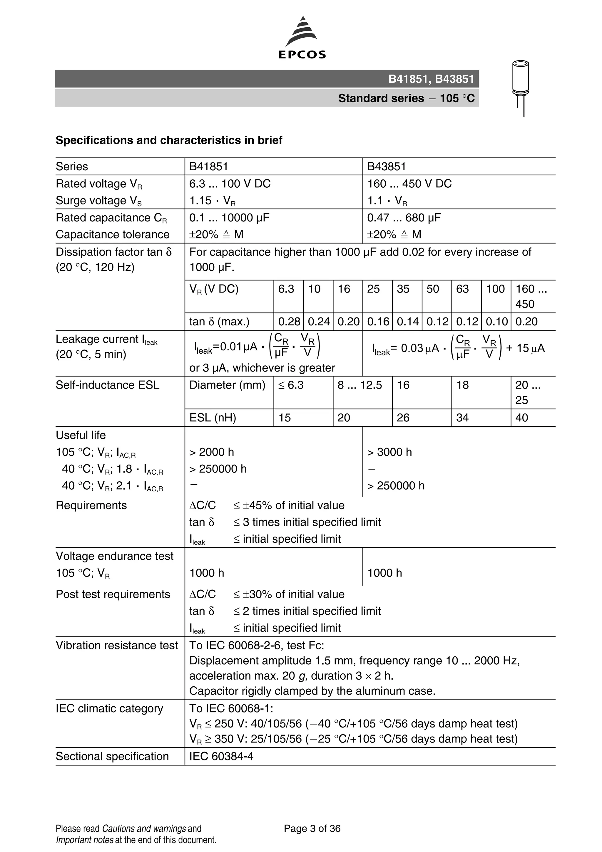
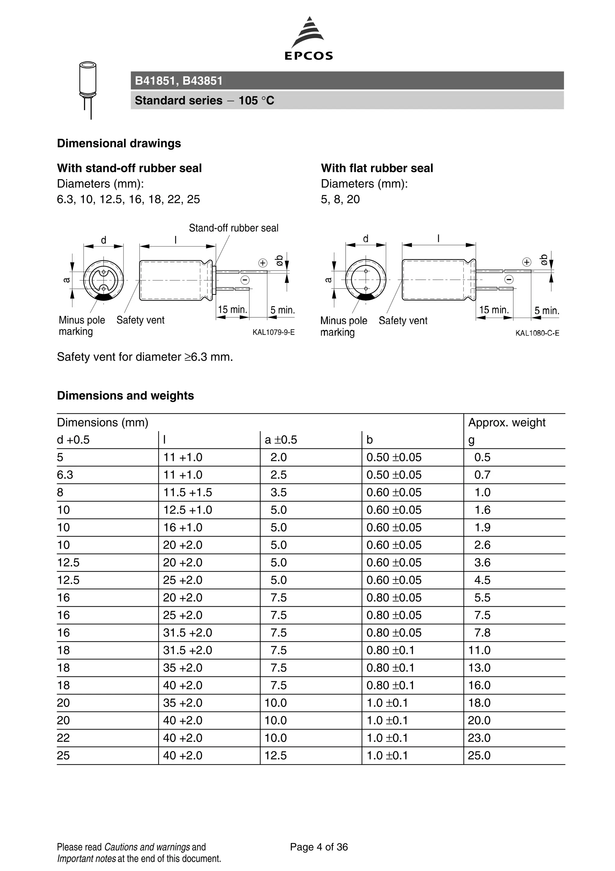
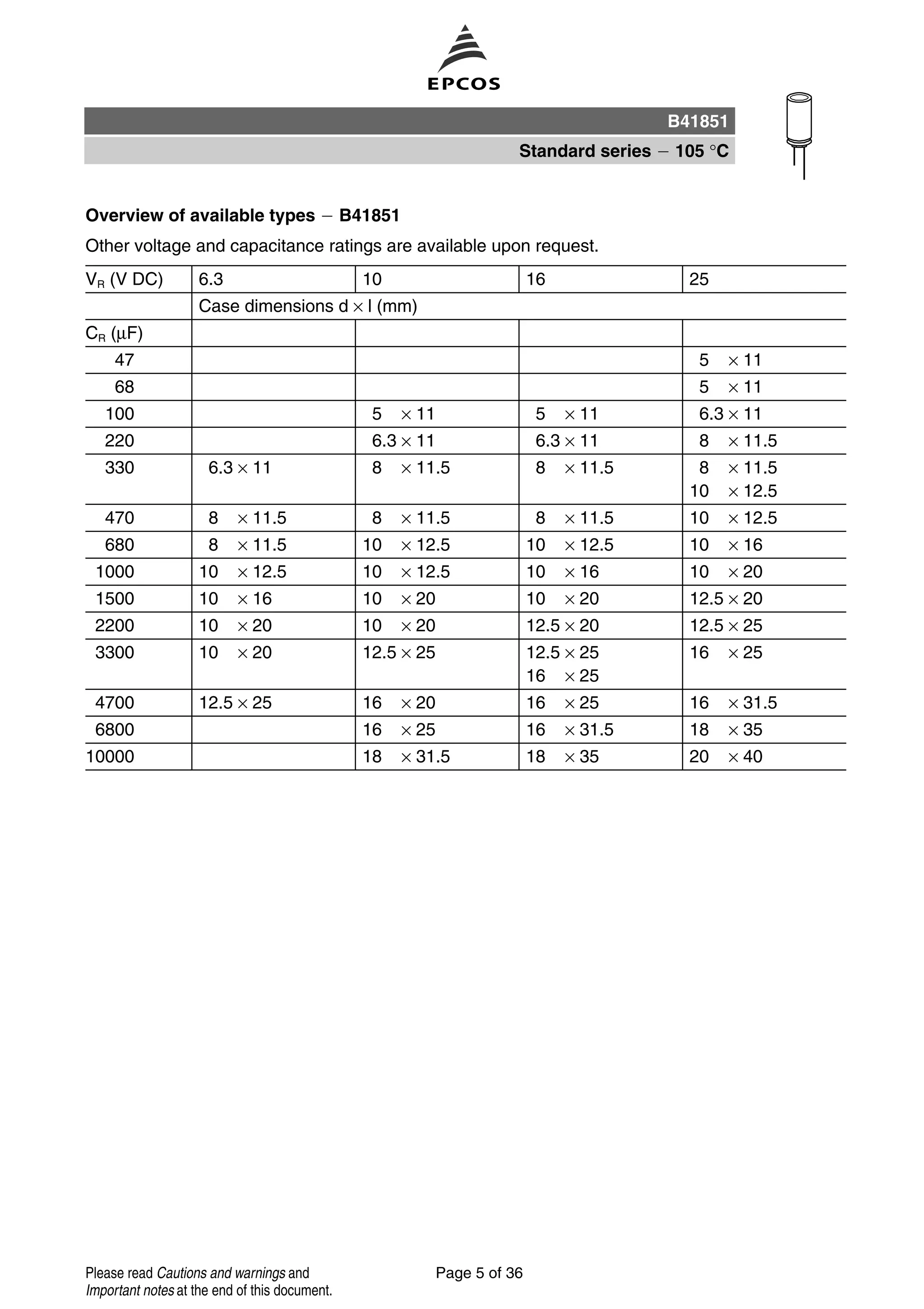
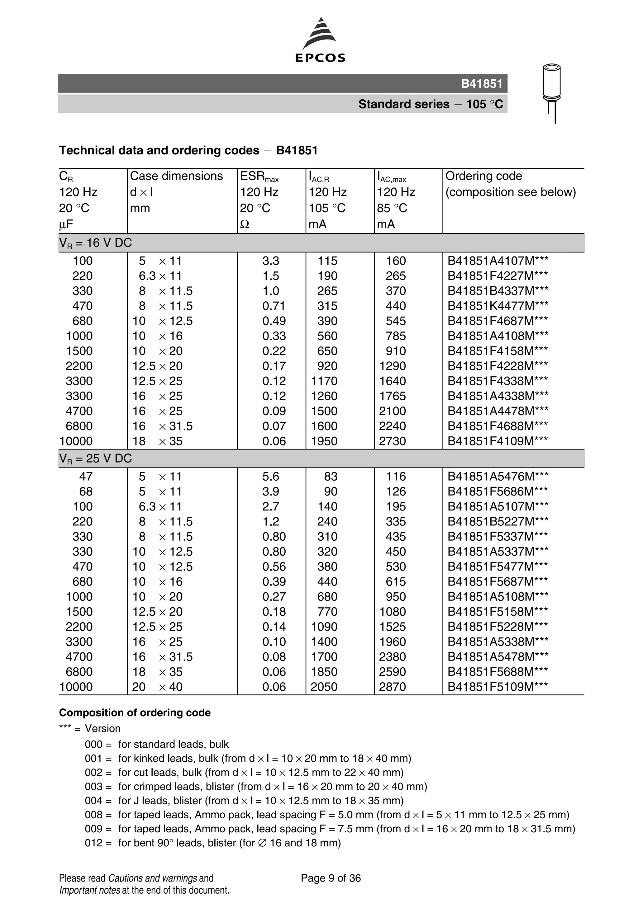
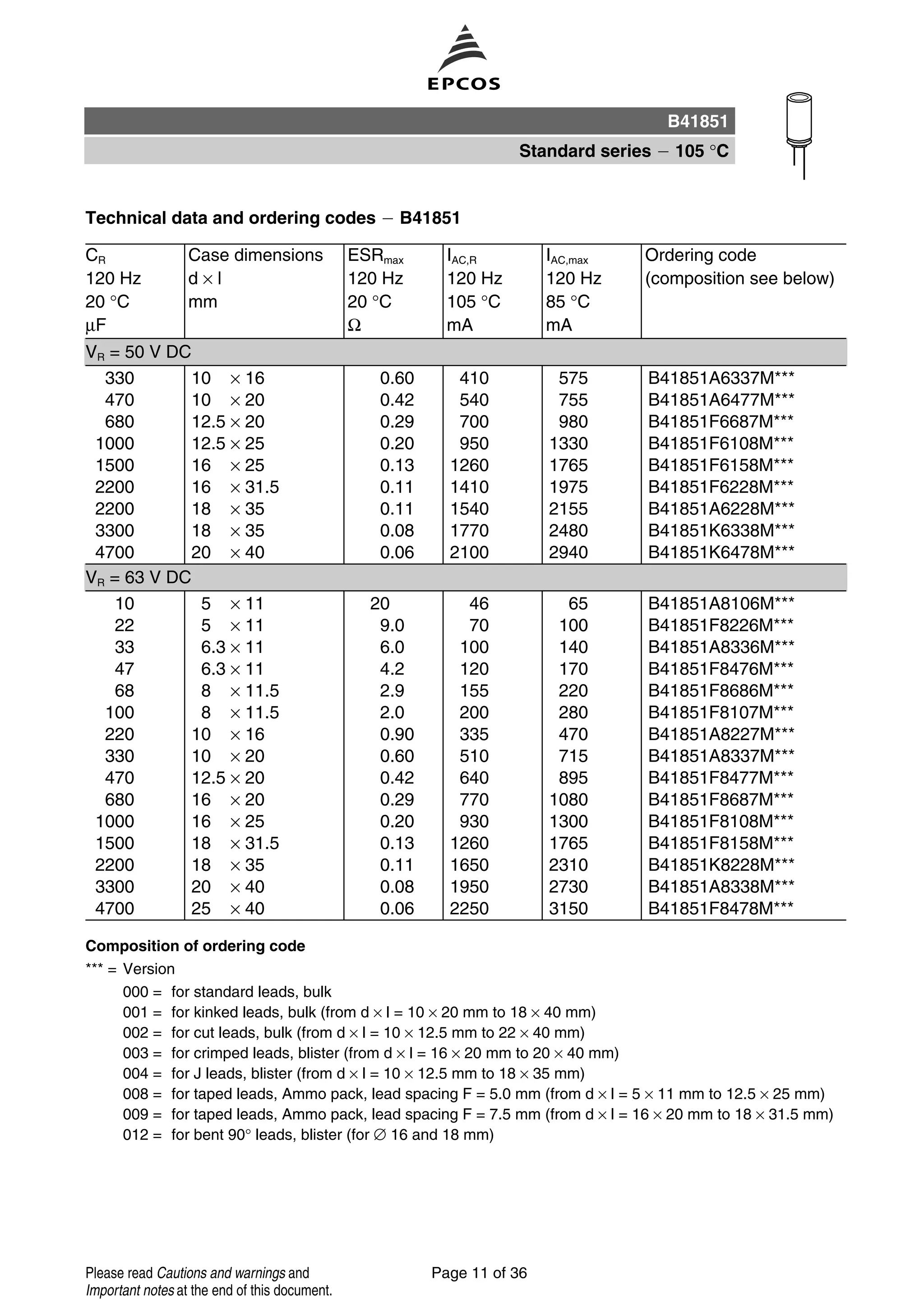
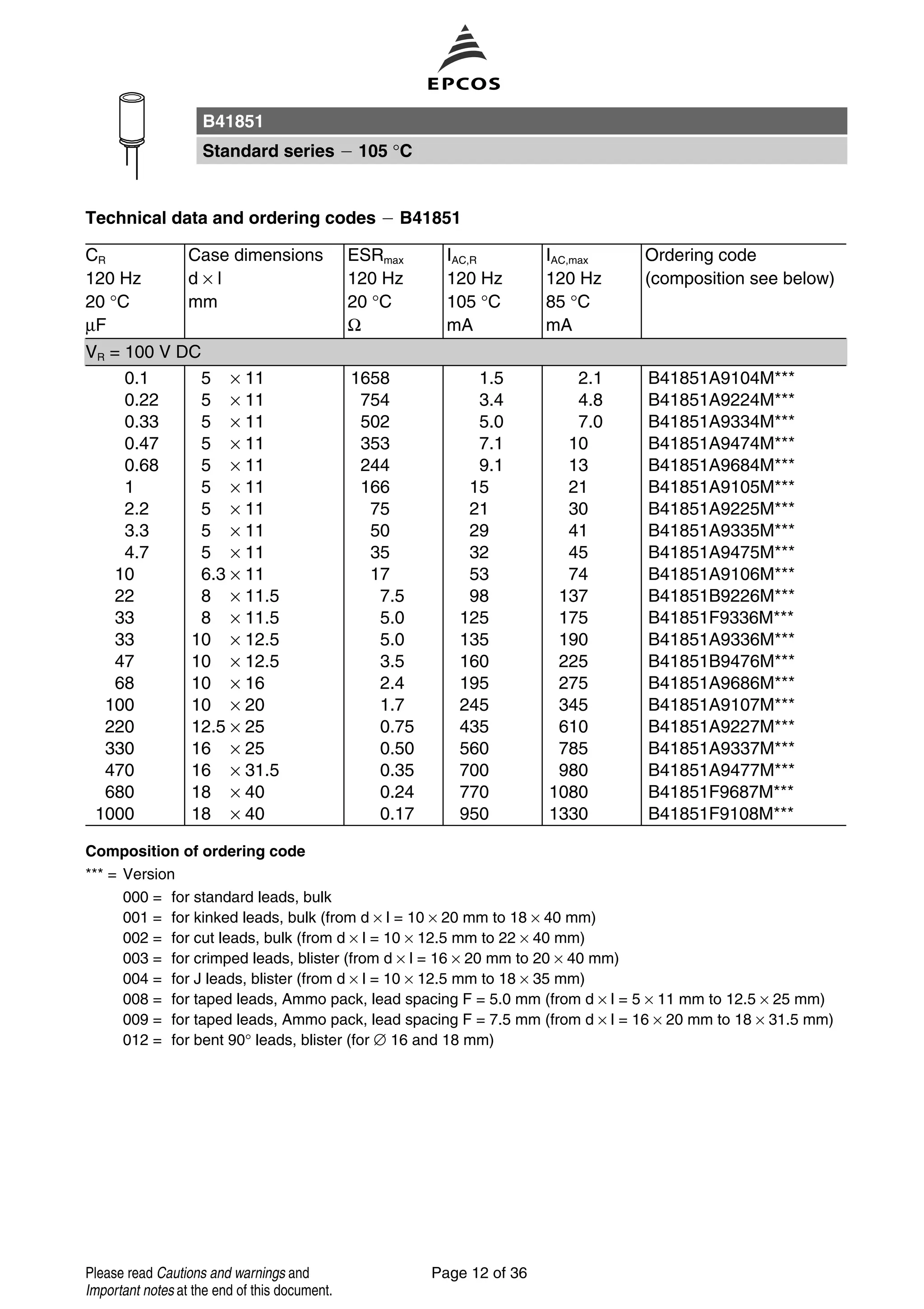
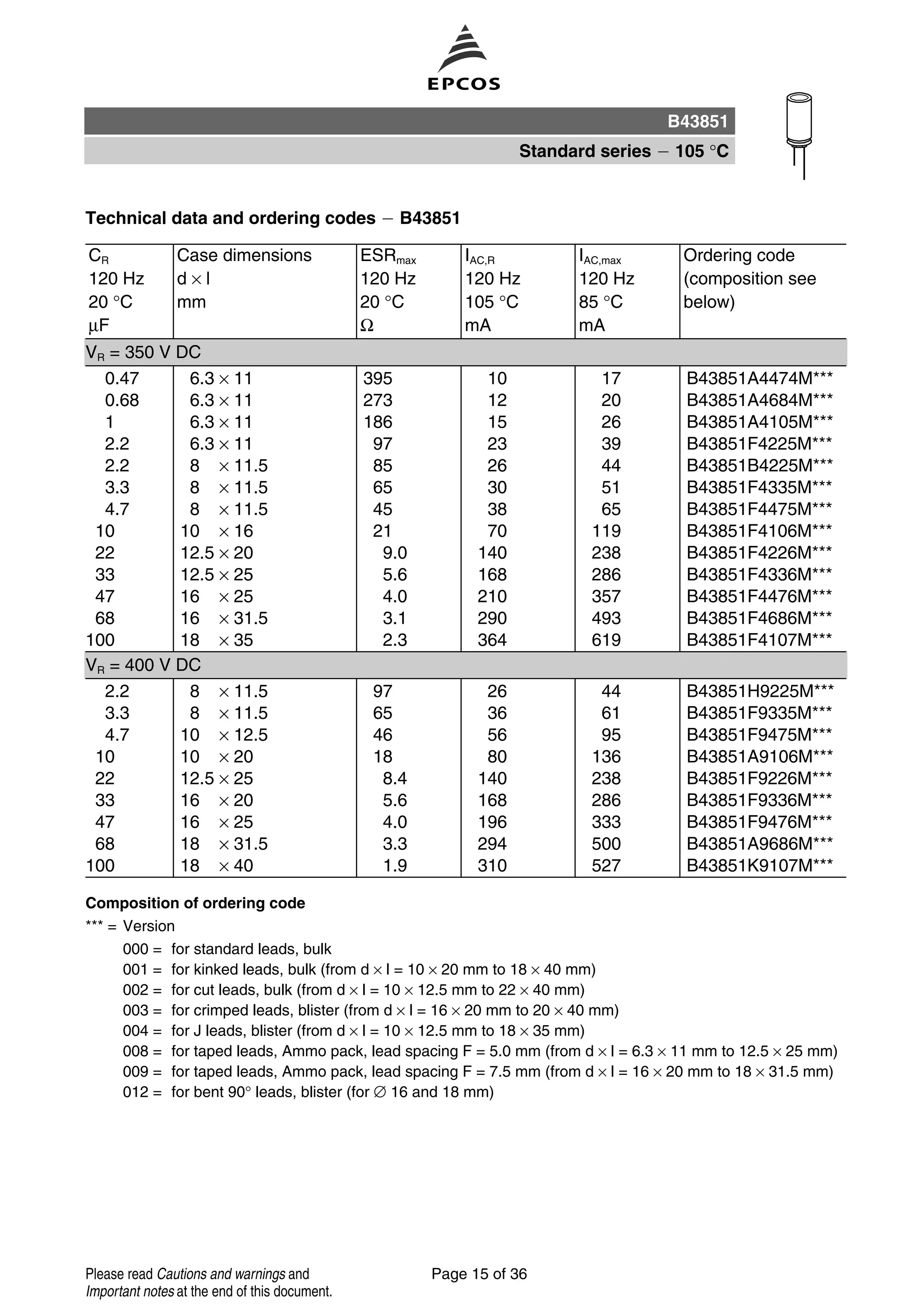
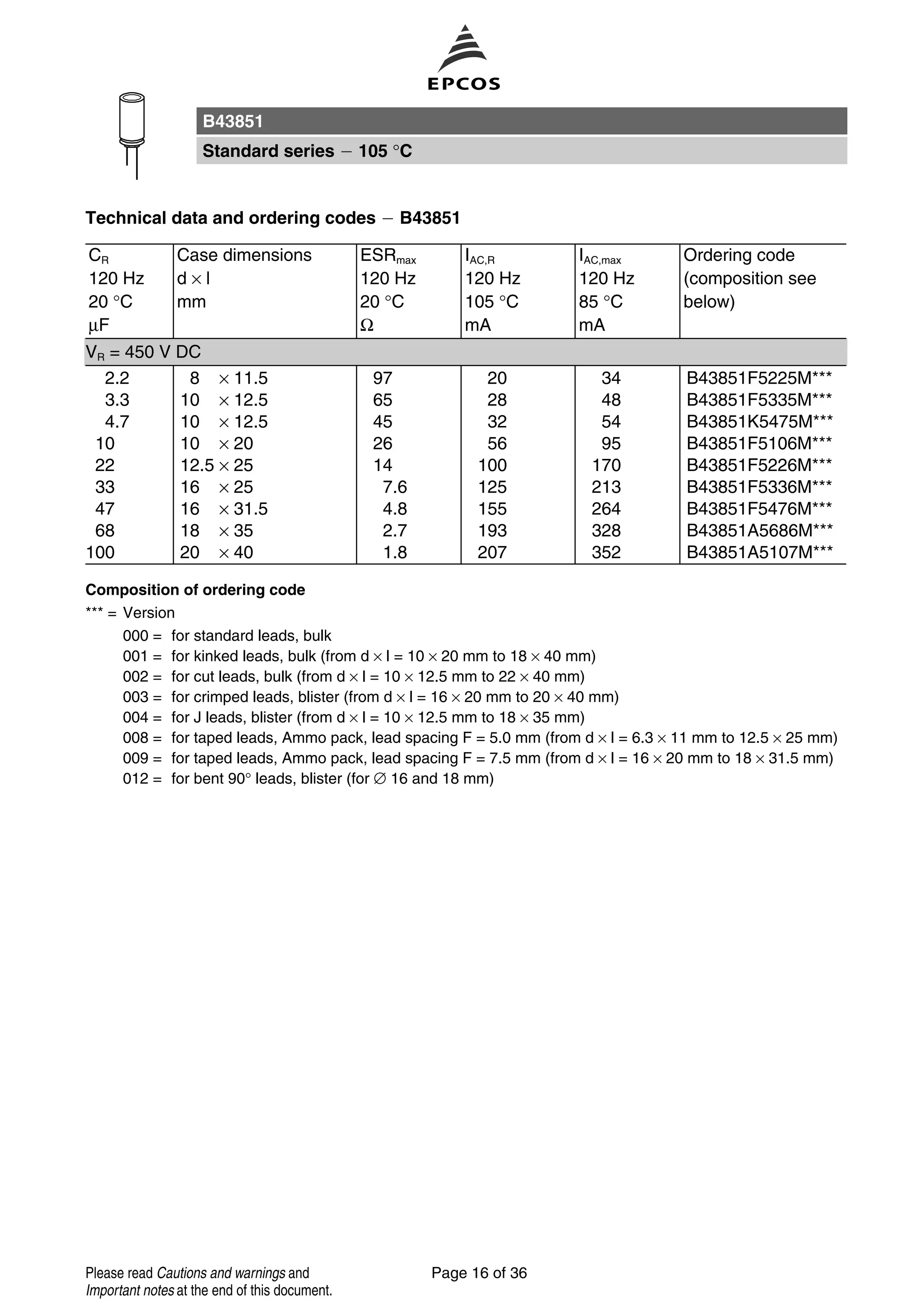
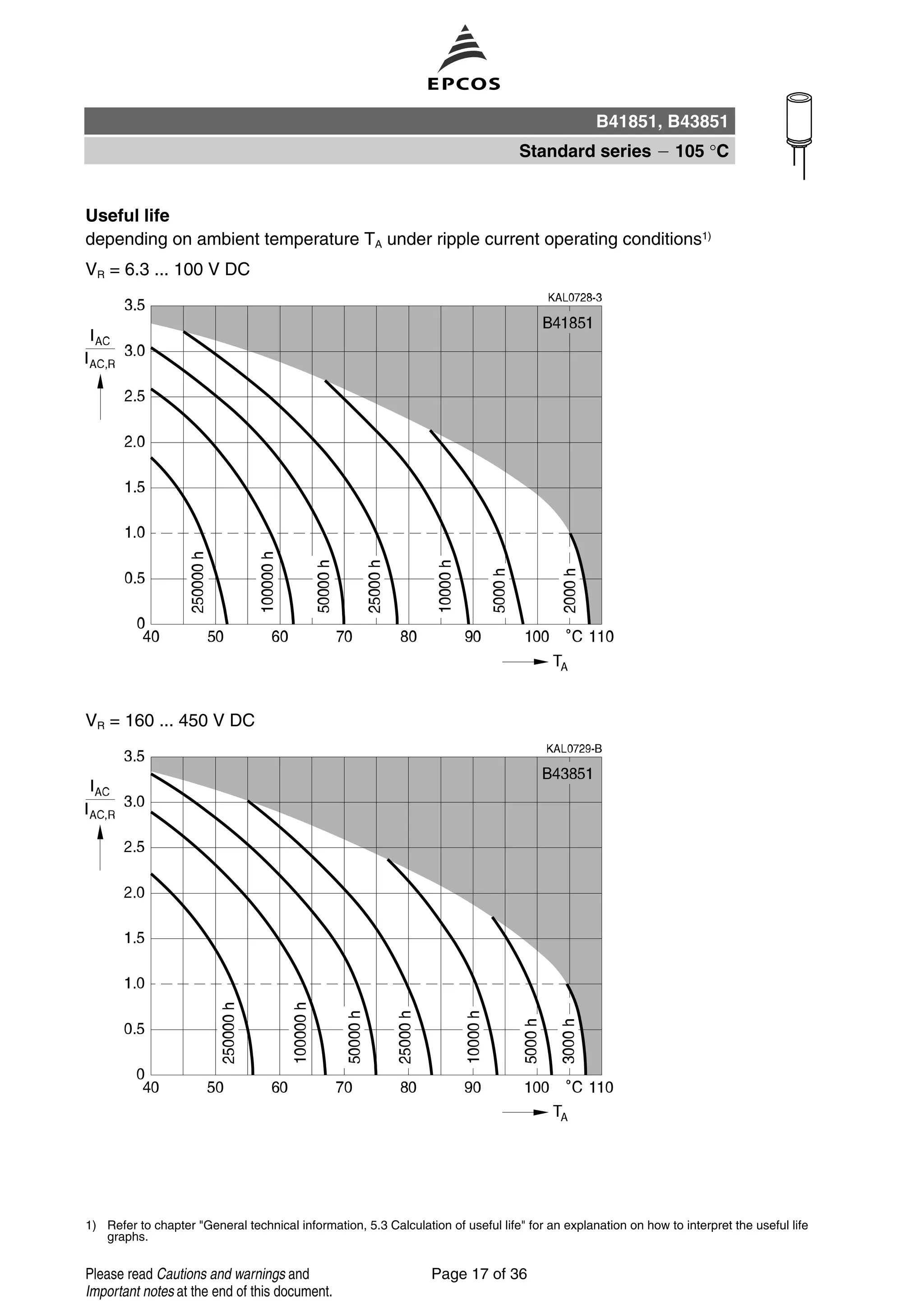
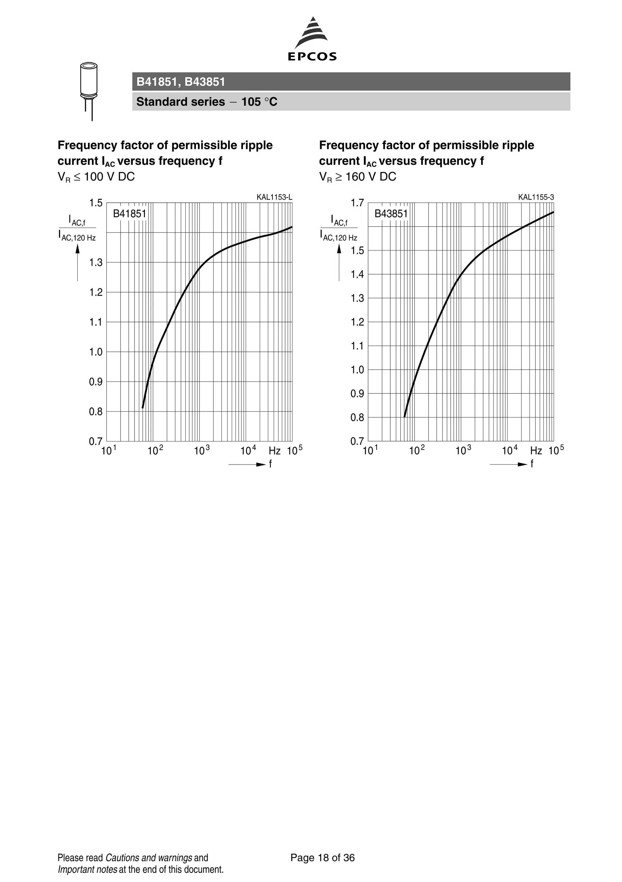
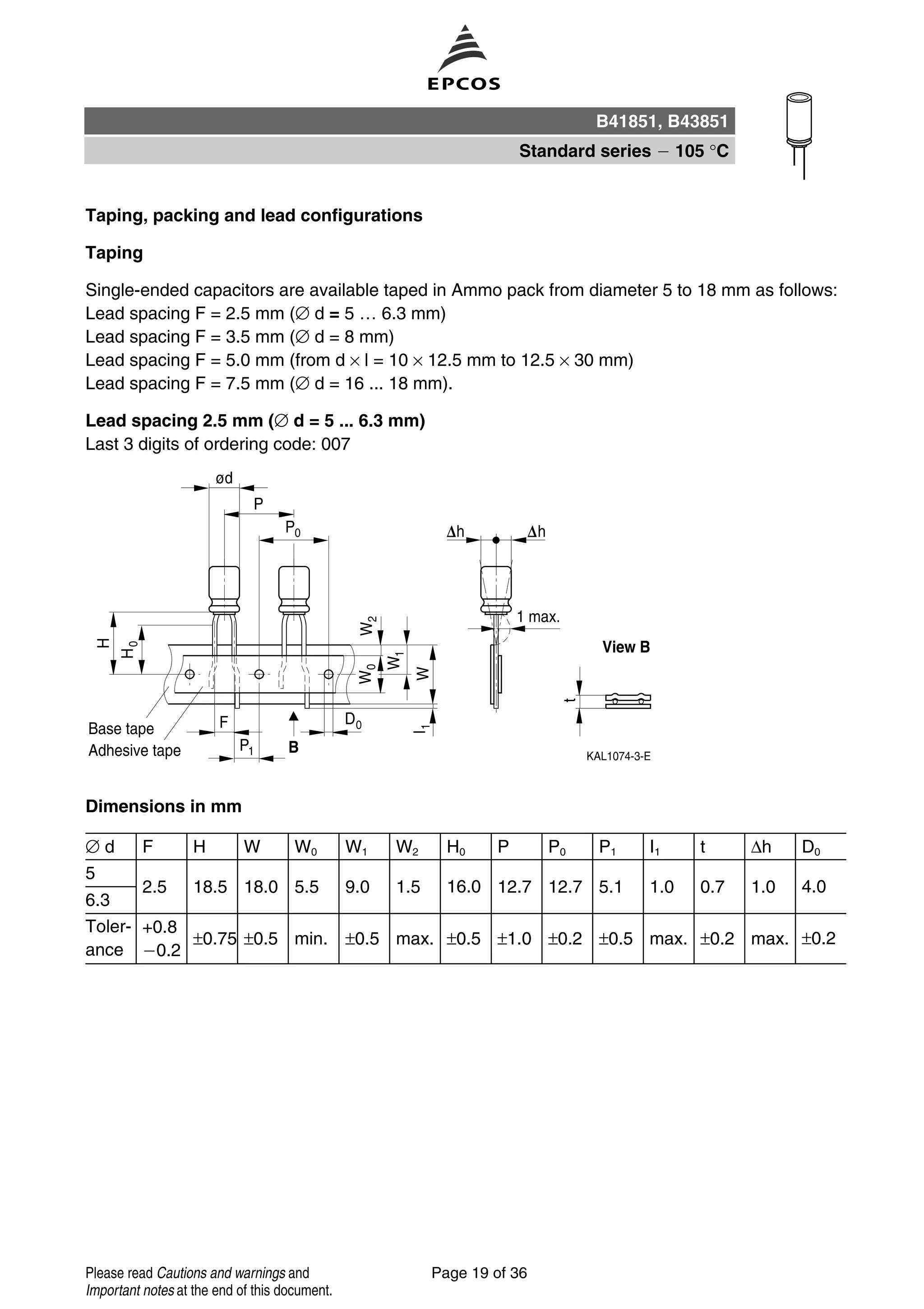
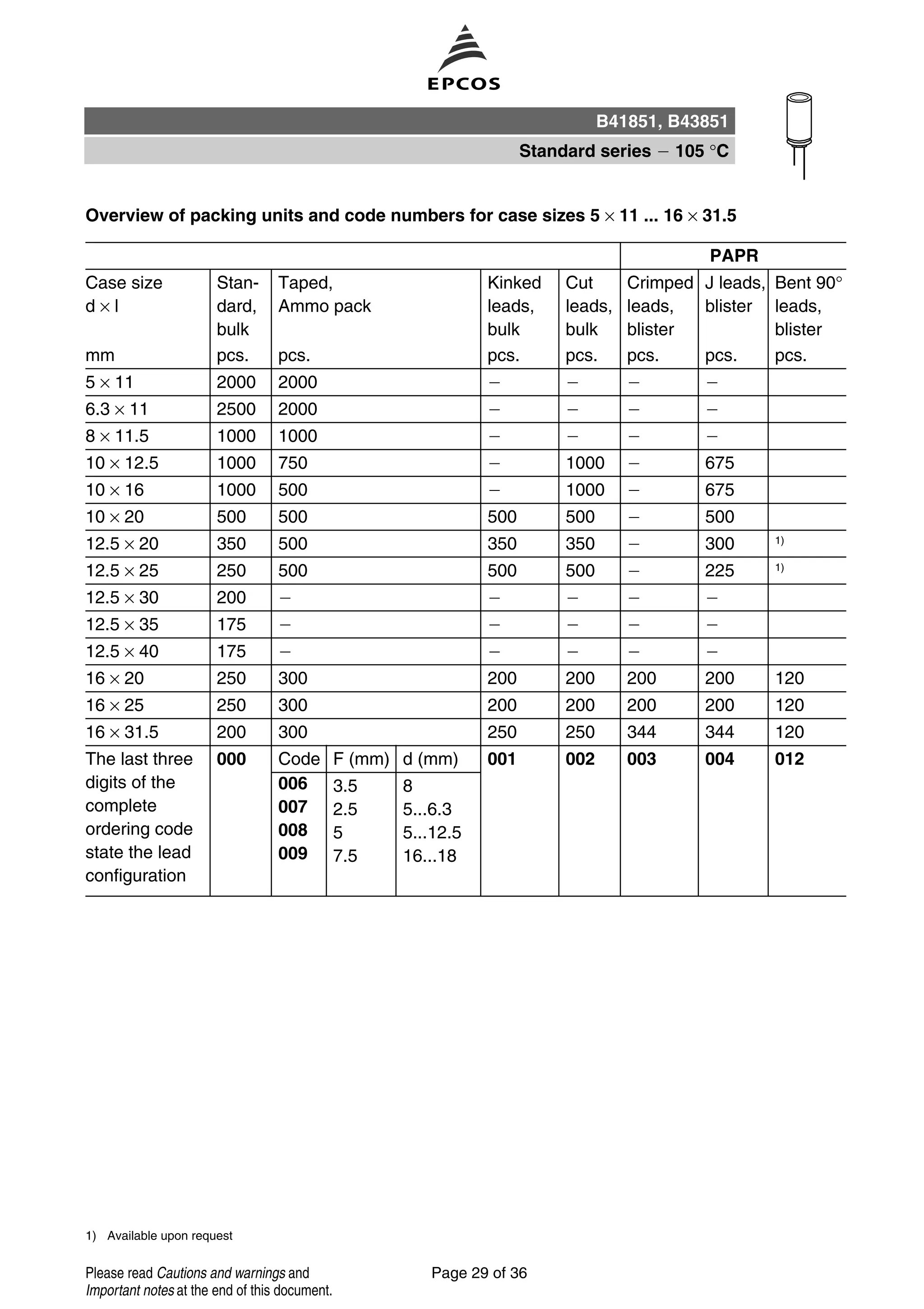
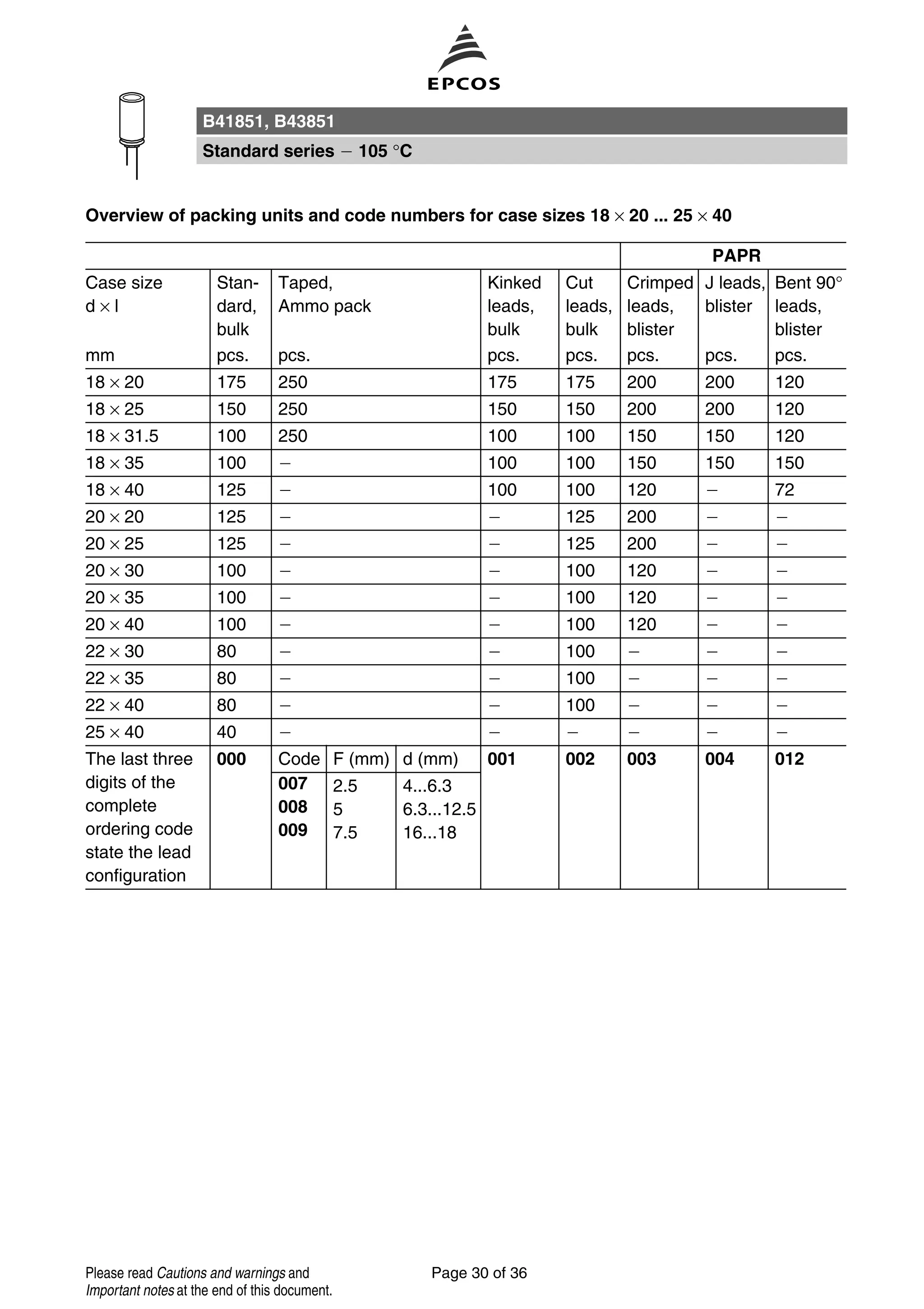
This document provides information on aluminum electrolytic capacitors including their applications, features, construction, specifications, characteristics, dimensions, and ordering codes. It describes general purpose capacitors suitable for filtering, coupling and pulse circuits in entertainment equipment as well as switch mode power supplies. Key specifications include rated voltage from 6.3V to 450V DC, capacitance from 0.1uF to 10,000uF, temperature rating of 105°C, and lifespans of over 2000 hours at rated voltage and temperature.
This document provides information on aluminum electrolytic capacitors in the B41821 and B43821 series for general purpose applications. It includes specifications for rated voltage, capacitance, dimensions, and other electrical characteristics. Tables list available capacitor types defined by capacitance and case size for different rated voltages. Ordering codes are provided following the same format.
This document provides specifications for aluminum electrolytic capacitors in the B41827 and B43827 product lines. Key details include:
- The capacitors are designed for general purpose applications in the entertainment industry with operating temperatures from -40°C to +85°C.
- They have miniaturized dimensions and a load life of 2000 hours at 85°C. Construction includes radial leads, an aluminum case with insulating sleeve, and safety vent for diameters 8mm or larger.
- Specifications include rated voltages from 6.3V to 450V DC, capacitance values from 0.47μF to 22,000μF, and dimensions for different case sizes. Electrical characteristics and ripple current
This document provides specifications for Vishay's standard thick film chip resistors. It includes details on features, electrical specifications, dimensions, packaging, and functional performance for various resistor models in different package sizes. The resistors offer stability at high temperatures, compatibility with lead-free soldering processes, and are AEC-Q200 qualified. Electrical specifications include resistance range, tolerance, temperature coefficient, and power ratings. Functional performance charts provide information on maximum pulse loads and voltages.
This document provides information on low ohm battery shunt resistors made by HTR. It includes specifications for 20 different resistor models varying in size, power rating, and resistance value between 0.000035 ohms and 0.002 ohms. The document discusses the physical and electrical characteristics including temperature range, tolerance, life testing results, and derating curves. It also provides packaging and ordering information.
Due to the stoppage of some 3M DriShield* moisture barrier bags, many companies are seeking alternatives to meet their needs. Protective Packaging can create static shielding bags and moisture barrier bags of all sizes from these materials.
3M Scotch 23 Tape - 3M Scotch Self-Amalgamating Rubber EPR Tapes
Scotch 23 Electrical Tape is a highly conformable 0.76mm thick, self amalgamating EPR (Ethylene Propylene Rubber) based, high voltage cable jointing tape. 3M Scotch 23 tape is non-vulcanising and shelf-stable with excellent electrical properties. Scotch 23 Tape can be used as insulation for low voltage applications as well as insulation for high voltage cable joints up to 69kV, especially 11kV and 33kV.
3M Scotch 23 Self-Amalgamating Tape Features
Can be used to splice and terminate cables with temperatures to 130°C
Based on Ethylene Propylene Rubber (EPR)
Physical and electrical properties are unaffected by the degree of stretch
Self-fusing Scotch 23 tape
Excellent electrical properties
Polyester liner which will not stick to the tape upon unwind
3M Scotch 23 Tape - Compatible with all solid dielectric cable insulations :-
Polyethylene (high and low density) cables
Cross-linked polyethylene (XLPE) cables
Polyvinyl chloride (PVC) cables
Butyl rubber cables
Ethylene Propylene Rubber (EPR) cables
Oil-based rubber cables
3M Scotch 23 Self-Amalgamating Tape Applications
Primary electrical insulation for splicing cable from 600V to 69kV
Primary insulation for building stress cones on cables up to 35kV
Jacketing on high voltage cable splices and terminations
Moisture sealing LV-HV electrical connections
Bus bar insulations
End sealing high voltage cables
Scotch Super 88 Vinyl Electrical Tape is a premium grade insulating tape designed for electrical insulation and mechanical protection. It is 0.2mm thick and can perform continuously between -18°C to 105°C. The tape has an aggressive adhesive and elastic backing that provides moisture-tight protection with minimum bulk. It also has excellent resistance to abrasion, moisture, weathering and chemicals. The tape is used to insulate wire splices up to 600V and forms protective covers for cable joints and terminations up to 1000V.
This document provides information on Scotch 22 Heavy Duty Vinyl Electrical Tape. It is a 10 mil thick premium grade vinyl tape designed for continuous use in ambient temperatures up to 80°C. The tape has excellent resistance to abrasion, moisture, acids, alkalies and weather conditions. It provides electrical and mechanical protection for wire and cable splices rated up to 600 volts and 80°C.
Scotch 35 vinyl electrical tape is a polyvinyl chloride tape with a rubber adhesive available in nine fade-resistant colors. It is designed for use in phase identification, color coding, and safety marking. The tape has excellent electrical insulating properties and is resistant to moisture, acids, and corrosion. It can operate continuously at 105°C and provides high dielectric breakdown and insulation resistance. The document provides details on the tape's specifications, installation, maintenance, and availability.
3M 33 Vinyl Electrical Tape is a general purpose insulating tape made of polyvinyl chloride. It has excellent resistance to abrasion, moisture, chemicals and weathering. The tape provides electrical insulation and mechanical protection for wire and cable joints rated up to 600V. It is a flame retardant tape suitable for indoor and outdoor applications. The document provides details on the tape's properties, applications, installation instructions, specifications and availability.
Barrier Material Mil prf-81705 d protectesd Than Nguyen
Military Packaging: Barrier Material: Water vapor proof, Electrostatic Protective, Electrostatic
and Electromagnetic Shielding, Flexible, Heat-Sealable
Scotch Super 33+ Vinyl Electrical Tape is a premium grade insulating tape designed for electrical insulation and mechanical protection. It is 0.178mm thick and can perform continuously in temperatures up to 105°C. The tape has excellent resistance to abrasion, moisture, acids, and weather conditions. It provides insulation for wire and cable splices up to 600V, as well as protective jacketing for bus applications and harnessing of wires.
Scotch Super 88 Vinyl Electrical Tape is a premium grade insulating tape designed for primary electrical insulation of wire and cable splices up to 600V and 105°C. It is 0.2mm thick with a rubber adhesive and can be applied in temperatures from -18°C to 105°C. The tape has high dielectric breakdown, adhesion, and tensile strength along with good elongation and resistance to weathering, chemicals, and corrosion. It should be wrapped in half-lapped layers with sufficient tension to insulate electrical connections and cable joints for indoor and outdoor use.
This document provides information on Scotchrap tapes, Scotchfil putty, and Scotchrap pipe primer for corrosion protection of pipes. Scotchrap tapes are polyvinyl chloride tapes with adhesive designed to resist corrosion on metal piping. Scotchfil putty is used to fill irregular surfaces before taping. The pipe primer prepares metal surfaces for tape application. Application instructions and product specifications are provided.
This document provides a summary of 3M's 8440 Series silicone rubber cold shrink connector insulators. It describes the product as open-ended, tubular sleeves that are factory expanded and shrink to form a tight seal when installed. The document lists the product's key features such as being simple to install without tools or heat, resisting moisture and chemicals, and having an operating temperature range of -55°C to 260°C. It also provides application examples, specifications, test data on performance properties, and ordering information.
3M Brand PST Cold Shrink Connector Insulators are open-ended, tubular rubber sleeves that are factory expanded and assembled onto a removable core. They are used to provide primary electrical insulation and physical protection for cable splices and connections rated up to 1000 volts. The insulators are made of EPDM rubber and are installed by removing the core, allowing the tube to shrink and form a waterproof seal around the cable or connection. They can be used for indoor, outdoor, overhead, buried, or submerged applications without additional heat or adhesives.
Scotchfil is an electrical insulation putty that comes in tape form. It is made of a synthetic rubber and provides excellent electrical insulation for low-voltage connections up to 600 volts. The putty can be used to insulate cable splices and fill irregular spaces, helping to create a uniform surface for taping. It adheres well without drying out and applies cleanly. The putty has high dielectric strength and insulation resistance, protecting connections from heat up to 80°C.
3M Cold Shrink Tubes Seal, Splice & Protect LV Power Cables 3M Cold Shrink Tube 8425-7 Cold Shrink Tube Min Diameter 9.9mm Cold Shrink Tube Max Diameter 17.8mm Cold Shrink Tube Length 178mm 3M Cold Shrink Tube is a pre-stretched EPDM rubber tubing, factory expanded and assembled onto a removable core. •Cold shrink provides a constant radial pressure seal •No heat required with 3M Cold Shrink - 100% cold applied •No specialist cable jointing or heat shrink tools required •Quality - long term reliability •Moisture resistant for submersible and outdoor applications 3M Cold Shrink Tubes are suitable for cable protection and moisture ingress protection - 3M Cold Shrink EPDM tubings are suitable as primary insulation on low voltage cables and cable splices up to 1000v AC. Cold shrink tubes provide electrical protection and moisture sealing for high-voltage, air-insulated connectors and cable lugs such as spacer cable and cable lug connections to bus bar. 3M cold shrink tubes also provide electrical insulation of secondary splices including copper or aluminium connectors.
Scotch 70 Silicone Rubber Electrical Tape is a high-temperature tape composed of self-fusing silicone rubber. It has excellent track and arc resistance as well as high dielectric strength, allowing it to be used as insulation for high-voltage cables and splices operating at temperatures up to 180°C. Testing showed tape-wrapped cable terminations resisted arcing for 400 hours compared to only 15 hours without tape when subjected to contamination. The document provides details on the tape's specifications and installation methods.
This document provides technical specifications for Glamet®, a self-supporting metal roof panel system insulated with polyurethane. It includes details on product approvals, panel construction, and tables of safe spans for different panel configurations under varying load conditions. The tables provide the maximum supported length (in meters) of panels based on thickness, material, load per square meter, and other factors.
This document provides specifications for ELP series aluminum electrolytic capacitors, including:
- Voltage and capacitance ranges from 16-100V and 470uF-47,000uF
- Temperature range of -40°C to +85°C
- Leakage current, dissipation factor, and impedance ratio specifications
- Requirements for capacitance change, dissipation factor, and leakage current after load life and shelf life testing.
This document summarizes various bands and charging accessories for the Apple Watch and Apple Watch 2. It describes active sport bands, woven bands, genuine leather bands, stainless steel bands, and charging solutions. The bands and accessories come in different styles, materials, colors and sizes and range in price from $24.99 to $74.99. The charging solutions allow the Apple Watch and phone to be charged simultaneously and conveniently.
This document provides product codes and pricing for various accessory bands, bracelets, and chargers that are compatible with Fitbit devices including the Fitbit Alta, Blaze, Flex2, and Charge2. The accessories include sport bands, genuine leather bands, woven bands, stainless steel bracelets, and charging cords. The document lists the product codes, descriptions, and MSRP for each accessory organized by the Fitbit device it is compatible with.
The document describes the life cycles of plants, animals, and humans. It explains that plants go through a life cycle of growth from seed to mature plant. For animals, it discusses different types of life cycles such as birds that are hatched from eggs and go through nestling and fledging stages before becoming adults, or insects that undergo incomplete or complete metamorphosis from egg to adult forms. The human life cycle is also outlined from infancy through adulthood.
This document provides an overview and specifications for the AN7149N integrated circuit, which is a dual 5.3W audio power amplifier designed for battery-powered applications such as radio cassette recorders. Key features include low quiescent current, high stability, low distortion and noise, and protection circuits. The IC requires few external components and is packaged in a compact 12-pin SIP package, enabling small, densely mounted designs.
This document outlines five free marketing opportunities for online businesses and publishers with limited budgets:
1. Personalize welcome letters for new subscribers to introduce yourself and promote your business.
2. Use goodbye letters to thank unsubscribing subscribers and ask for feedback to improve.
3. Include an effective email signature in online communications to advertise your business.
4. Add a brief postscript (PS) to capture attention and promote offers.
5. Collaborate with other publishers on a group subscription page to cross-promote each other's publications.
Diskusi mengalir tentang kekuatan dan kelemahan manusia tanpa pertolongan Allah. Semua kemampuan dan kedudukan manusia tidak berarti apa-apa bila tidak sadar akan kebesaran Allah dan memohon pertolongan-Nya. Hanya Allah yang maha kuasa atas segala sesuatu.
The document discusses strategies for Calvin Klein to succeed in the Vietnam fashion market. It notes that international fashion brands have invested heavily in Vietnam. To compete, Calvin Klein must effectively build and develop its brand while creating distinctive strategies to attract customers. Specifically, the document recommends that Calvin Klein improve its product design and colors to appeal to Vietnamese customers, expand its distribution channels beyond major cities, implement effective marketing communications, and enhance its customer service.
This document provides the website address www.DataSheet4U.com repeated multiple times. The website DataSheet4U.com appears to provide data sheets and technical documentation for various components and technologies. The repeated listing of the website address serves to prominently advertise and promote awareness of the website and resources that it offers related to data sheets.
This 3 sentence document warns that the material is copyrighted by its manufacturer. It repeats this message of copyright 3 times without providing any other context or information about the material. The summary reiterates the copyright message and notes the repetitive nature of the short document.
The BA5406 is a dual-OTL monolithic power IC containing two high-output, low-frequency power amplifiers. It can output 5W with a 12V power supply or 2.8W with a 9V power supply into a 3Ω load. It has low "pop" noise when power is applied and generates little radio-band noise, making it suitable for stereo radio cassette players and other audio applications. The IC has features such as good low-voltage characteristics, channel balance, and distortion performance in a compact 12-pin package.
1. The document describes a student named Nguyễn Triệu Phúc Hải taking a final exam. It provides instructions that writing must be in blue pen and materials are allowed.
2. The student summarizes their role in a charity project called "Shining Rainbow" where they helped sell t-shirts and tickets. They describe promotion methods and feelings of learning valuable skills.
3. The student discusses continuing helping society by volunteering with groups, teaching skills, supporting community programs, and engaging in environmental initiatives.
This document provides specifications for ELP series aluminum electrolytic capacitors including:
- Voltage and capacitance ranges from 16-100V and 470uF-47,000uF
- Temperature range of -40°C to +85°C
- Leakage current and dissipation factor specifications
- Load life and shelf life test requirements
- Standard product dimensions and maximum ripple current for different capacitance sizes
The document is a resume for Nguyen Trieu Phuc Hai. It summarizes his objective to obtain part-time work while attending Keuka College. It details his education at Keuka College studying International Business and expected graduation in May 2015. It also lists work experience including projects at Keuka College and part-time jobs to gain experience in international business. Hobbies and volunteer experience are also mentioned.
This document provides information on aluminum electrolytic capacitors in the B41821 and B43821 series for general purpose applications. It includes specifications for rated voltage, capacitance, dimensions, and other electrical characteristics. Tables list available capacitor types defined by capacitance and case size for different rated voltages. Ordering codes are provided following the same format.
This document provides information on aluminum electrolytic capacitors in the B41821 and B43821 series for general purpose applications. It includes specifications for rated voltage, capacitance, dimensions, and performance characteristics. Tables list available capacitor types defined by capacitance and case size for different rated voltages. The document also provides test procedures and standards that the capacitors comply with.
This document provides information on aluminum electrolytic capacitors in the B41821 and B43821 series for general purpose applications. It includes specifications for rated voltage, capacitance, dimensions, and other electrical characteristics. Tables list available capacitor types defined by capacitance and case size for different rated voltages. Ordering codes are provided following the same format.
This document provides specifications for aluminum electrolytic capacitors in the B41827 and B43827 product lines. Key details include:
- The capacitors are designed for general purpose applications in the entertainment industry with operating temperatures from -40°C to +85°C.
- They have miniaturized dimensions and a load life of 2000 hours at 85°C. Construction includes radial leads, an aluminum case with insulating sleeve, and safety vent for diameters 8mm or larger.
- Specifications include rated voltages from 6.3V to 450V DC, capacitance values from 0.47μF to 22,000μF, and dimensions for different case sizes. Electrical characteristics and ripple current
This document provides information on metallized polyester film capacitors, including their typical applications, features, construction, technology, overview of available types with lead spacing and capacitance ratings, ordering codes, and packaging. The capacitors can be used in applications such as compact fluorescent lamps, blocking, coupling, decoupling, and bypassing. They utilize polyethylene terephthalate film with stacked or wound construction and epoxy resin coating.
This document provides information on capacitors available from Garrett Electronics Corp., including:
- Product listings for aluminum electrolytic, ceramic, tantalum, and other capacitor types in both surface mount and through-hole packages.
- Specification sheets and dimensions for popular capacitor series from manufacturers like Rubycon and AVX.
- Value-added services like packaging options for bulk parts or custom engineering design kits.
- Contact information for Garrett Electronics Corp. including their website, phone number, fax, and address in Santa Maria, California.
This document provides information on metallized polyester film capacitors of the B32231 series/type, including their typical applications, construction, terminals, ordering codes, technical specifications, mounting guidelines, and cleaning recommendations. The capacitors are designed for applications such as smoothing and filtering, can operate at temperatures up to 100°C, and have voltage ratings from 100V to 630V and capacitance values from 0.1μF to 10μF.
Dienhathe.com catalogue epcos-capacitor_phicap_b32344dDien Ha The
This document provides specifications for various film capacitors used for power factor correction. It includes information on construction, features, technical data, test data, design data, and specification tables for different capacitor types with varying voltages, frequencies, capacitances, dimensions, weights and quantities per box. The capacitors are designed for three-phase power factor correction applications.
The document discusses electrostatic discharge (ESD) and how ESD capacitors are used to protect integrated circuits from ESD events. It provides an overview of ESD, its causes and effects, and outlines two main functions of ESD capacitors - diverting charge from ESD pulses and absorbing charge to reduce voltage. The document also details KEMET's portfolio of ESD rated multilayer ceramic capacitors (MLCCs) in various case sizes, capacitance values, and ESD withstand ratings according to industry testing standards. It emphasizes that while any capacitor can provide ESD protection, ESD rated capacitors are designed and tested to guarantee specified ESD withstand performance.
SIBA URDC DC fuses are available for use on traction, battery and railway circuit applications - traction fuses are designed for heavy duty circuit protection to following standards UIC550, IEC60269 and VDE 0636-40.
SIBA URZ cylindrical fuses for semiconductor protection are available with high interrupting rating up to 300 kA and voltage ratings AC 250v to AC 1000v. URZ fuses can be fitted with built-in striker pin for fuse blown indication or operation of microswitches. Semiconductor protection according to IEC 60269-1.
Fuses For Semiconductor Protection
Cylindrical Fuses – European Standard
SIBA cylindrical ultra-rapid fuses are available in 6 different sizes and can be fitted with or without built-in striker pin for fuse blown indication or operation of microswitches.
Standard: IEC 60269-1 and -4
DIN VDE 0636-23
UL 248-13
Class: gR/aR/gRL fuses
Current ratings: 125 mA – 200 A
Fuse size and voltage rating:
5 x 20 mm: AC 250 V
6.35 x 32 mm: AC 500 – 1000 V
10 x 38 mm: AC 600 – 1000 V
14 x 51 mm: AC 500/600V – 690/700 V
22 x 58 mm: AC 500/600 V – 690/700 V
27 x 60 mm: AC 660 V – 1000 V
High interrupting rating up to 300 kA
Voltage rating AC 250 V up to AC 1000 V
Protection of semiconductors according to IEC 60269-1 and -4
With or without integrated striker pin
Class aR according to IEC 60269-4 and DIN VDE 0636-40
Class gR according DIN VDE 0636-40
Dienhathe.com catalogue epcos-capacitor_phasecapDien Ha The
Khoa Học - Kỹ Thuật & Giải Trí: http://phongvan.org
Tài Liệu Khoa Học Kỹ Thuật: http://tailieukythuat.info
Thiết bị Điện Công Nghiệp - Điện Hạ Thế: http://dienhathe.vn
Case ih 1200 and early riser series planters service repair manualfjjskekdmem
This document is a repair manual for 1200 and Early Riser series planters. It contains 18 books that cover hydraulic, electrical, and electronic systems for different planter models. Each book has a publication number and covers a specific system. The manual provides instructions on inspecting and testing electrical connectors, as well as guidelines for measuring voltage and resistance. It also includes tables with torque specifications for hydraulic fittings and fasteners.
Case ih 1200 and early riser series planters service repair manualufjskefsmekm
This document provides an introduction and instructions for repairing 1200 and Early Riser series planters. It includes torque specifications for hydraulic tubes and fittings, fasteners, and electrical connector inspection procedures. The document is divided into 18 books that cover hydraulic, electrical, and electronic systems for different planter models. Books can be ordered separately or as a complete repair manual set.
Dienhathe.com catalogue epcos-capacitor_deltacapDien Ha The
Khoa Học - Kỹ Thuật & Giải Trí: http://phongvan.org
Tài Liệu Khoa Học Kỹ Thuật: http://tailieukythuat.info
Thiết bị Điện Công Nghiệp - Điện Hạ Thế: http://dienhathe.vn
The document outlines 8 steps for designing the structure of a building: 1) selecting a building plan, 2) drawing the plan in AutoCAD, 3) calculating loads, 4) creating a STAAD model, 5) sizing columns and beams, 6) entering loads, 7) selecting materials, and 8) designing structural elements. It then provides details on load calculations, beam sizes and reinforcement, and column sizes for a sample college building design.
This document provides information on HTR's VHIA series of wire wound resistors. Key details include:
- The resistors have a flame retardant silicone coating and operate from 0.5W to 25W with tolerances as close as 1%.
- Dimensions, resistance ranges, weights, and packaging configurations are provided for each model.
- Electrical characteristics include voltage and power ratings, temperature coefficients, and pulse capability performance.
- Graphs illustrate temperature rise vs power and maximum pulse power vs pulse duration for various models.
Original Zener Diode 1N5366B 5366B 5366 5W 39V NewAUTHELECTRONIC
This document provides information on ON Semiconductor's 1N53 Series 5 Watt Zener diodes. It includes specifications for over 40 Zener diode models with voltages ranging from 3.3V to 200V. The diodes feature tight voltage limits, low leakage current, and are packaged in axial lead plastic packages for protection in various environments. Maximum ratings and electrical characteristics like Zener voltage, impedance, and surge current are specified for each model in tables.
The Rosenberg Group produces axial and centrifugal fans for applications such as transformer cooling. They have 350 employees in Germany and 1400 worldwide. Their centrifugal fans come in sizes from 250-630mm and feature aluminum impellers and external rotor motors. Their axial fans range from 450-800mm and have sickle-shaped aluminum blades and external rotor motors. Both fan types are suited for transformer cooling applications as they help dissipate heat and cool the transformer, allowing for higher loads, improved efficiency, and longer life.
This document provides information on the BA6238A, BA6238AN, BA6239A, and BA6239AN motor driver ICs, which incorporate two reversible motor drivers suitable for driving small DC brush motors. Each IC contains built-in power transistors for motor driving and thermal shutdown circuits to protect from overheating. The document includes specifications, application examples, operating procedures, and electrical characteristic curves for the motor driver ICs.
The BA6229 is a monolithic integrated circuit used for driving reversible motors. It contains a logic section that can set brake and open modes and an output transistor that controls forward and reverse motor operations. Some key features include a built-in power transistor for motor driving up to 1.2A, operation from 8-23V supply voltage, and four output modes for forward, reverse, stop, and brake functions.
The BA6219B and BA6219BFP-Y are reversible motor driver ICs suitable for brush motors. They have two logic inputs that allow four output modes: forward, reverse, idling, and braking. The motor speed can be set arbitrarily by controlling the voltage applied to the motor. Key features include a large output current, thermal shutdown protection, and pins to set the output voltage. Application examples are provided.
The BA6209 and BA6209N ICs are motor driver chips that can operate motors in forward, reverse, or braking modes. They can handle motor currents up to 1.6A and have features such as integrated braking, rush current absorption, and motor speed control via an input pin. The chips are designed to drive brush motors typically used in devices like VCRs and cassette recorders.
The BA6191 is a 2-channel motor driver IC that can be used in applications like CD players. It has four operating modes - forward, reverse, stop, and brake - that are selected by two control logic inputs. It uses a negative power supply and has protections like thermal shutdown and power supply voltage drop muting. The IC outputs a voltage twice the reference voltage in forward and reverse modes and stops output or brakes in the other modes.
This document provides specifications for the BA5417, a dual power amplifier IC compatible with 6-15V power supplies. It is designed for use in radio cassette and mini component players. Key features include high output power of up to 5W per channel, low distortion of 0.1% or less, and standby switching functions. The document provides detailed electrical characteristics, application circuit examples, and test data graphs.
This document consists of 10 repetitions of the same sentence stating that the material is copyrighted by its respective manufacturer. It does not provide any other context or information.
The BA3822LS, BA3822FS, BA3823LS, and BA3824LS are monolithic, five-point stereo graphic equalizer ICs. Each IC has two channels with independently set center frequencies. These ICs are ideal for home stereo systems, radio cassette players, and car stereos due to their wide operating voltage range and compact packages. The ICs differ in their amount of boost and cut control, so choose according to your application requirements.
The BA3812L is a five-channel graphic equalizer integrated circuit that provides all necessary functions on a single chip. It features low distortion, low noise, and wide dynamic range, making it suitable for hi-fi stereo applications. The five center frequencies can be independently set using external capacitors. By using two ICs, a 10-point graphic equalizer can be created. The IC has a wide operating voltage range of 3.5V to 16V allowing it to be used in various stereo equipment.
2. General-purpose grade capacitors
Applications
General-purpose applications in the entertainment industry
Semi-professional to professional application range
For filtering, coupling and pulse circuits
Switch-mode power supplies
Features
Compact dimensions
High CV product, i.e. very compact
RoHS-compatible
Construction
Radial leads
Charge-discharge proof, polar
Aluminum case with insulating sleeve
Minus pole marking on the insulating sleeve
Case with safety vent from diameter 6.3 mm
Delivery mode
Terminal configurations and packing:
Bulk
Taped, Ammo pack
Cut
Kinked
PAPR (protection against polarity reversal):
crimped leads, J leads, bent leads
Refer to chapter "Single-ended capacitors Taping, packing
and lead configurations" for further details and ordering
example.
Single-ended capacitors B41851, B43851
Standard series 105 °C
Page 2 of 36Please read Cautions and warnings and
Important notes at the end of this document.
3. Specifications and characteristics in brief
Series B41851 B43851
Rated voltage VR 6.3 ... 100 V DC 160 ... 450 V DC
Surge voltage VS 1.15 VR 1.1 VR
Rated capacitance CR 0.1 ... 10000 µF 0.47 ... 680 µF
Capacitance tolerance ±20% M ±20% M
Dissipation factor tan δ
(20 °C, 120 Hz)
For capacitance higher than 1000 µF add 0.02 for every increase of
1000 µF.
VR (V DC) 6.3 10 16 25 35 50 63 100 160 ...
450
tan δ (max.) 0.28 0.24 0.20 0.16 0.14 0.12 0.12 0.10 0.20
Leakage current Ileak
(20 °C, 5 min)
or 3 µA, whichever is greater
Self-inductance ESL Diameter (mm) ≤ 6.3 8 ... 12.5 16 18 20 ...
25
ESL (nH) 15 20 26 34 40
Useful life
105 °C; VR; IAC,R > 2000 h > 3000 h
40 °C; VR; 1.8 IAC,R > 250000 h
40 °C; VR; 2.1 IAC,R > 250000 h
Requirements ∆C/C ≤ ±45% of initial value
tan δ ≤ 3 times initial specified limit
Ileak ≤ initial specified limit
Voltage endurance test
105 °C; VR 1000 h 1000 h
Post test requirements ∆C/C ≤ ±30% of initial value
tan δ ≤ 2 times initial specified limit
Ileak ≤ initial specified limit
Vibration resistance test To IEC 60068-2-6, test Fc:
Displacement amplitude 1.5 mm, frequency range 10 ... 2000 Hz,
acceleration max. 20 g, duration 3 × 2 h.
Capacitor rigidly clamped by the aluminum case.
IEC climatic category To IEC 60068-1:
VR ≤ 250 V: 40/105/56 ( 40 °C/+105 °C/56 days damp heat test)
VR ≥ 350 V: 25/105/56 ( 25 °C/+105 °C/56 days damp heat test)
Sectional specification IEC 60384-4
B41851, B43851
Standard series 105 °C
Page 3 of 36Please read Cautions and warnings and
Important notes at the end of this document.
4. Dimensional drawings
With stand-off rubber seal
Diameters (mm):
6.3, 10, 12.5, 16, 18, 22, 25
With flat rubber seal
Diameters (mm):
5, 8, 20
Safety vent for diameter ≥6.3 mm.
Dimensions and weights
Dimensions (mm) Approx. weight
d +0.5 l a ±0.5 b g
5 11 +1.0 2.0 0.50 ±0.05 0.5
6.3 11 +1.0 2.5 0.50 ±0.05 0.7
8 11.5 +1.5 3.5 0.60 ±0.05 1.0
10 12.5 +1.0 5.0 0.60 ±0.05 1.6
10 16 +1.0 5.0 0.60 ±0.05 1.9
10 20 +2.0 5.0 0.60 ±0.05 2.6
12.5 20 +2.0 5.0 0.60 ±0.05 3.6
12.5 25 +2.0 5.0 0.60 ±0.05 4.5
16 20 +2.0 7.5 0.80 ±0.05 5.5
16 25 +2.0 7.5 0.80 ±0.05 7.5
16 31.5 +2.0 7.5 0.80 ±0.05 7.8
18 31.5 +2.0 7.5 0.80 ±0.1 11.0
18 35 +2.0 7.5 0.80 ±0.1 13.0
18 40 +2.0 7.5 0.80 ±0.1 16.0
20 35 +2.0 10.0 1.0 ±0.1 18.0
20 40 +2.0 10.0 1.0 ±0.1 20.0
22 40 +2.0 10.0 1.0 ±0.1 23.0
25 40 +2.0 12.5 1.0 ±0.1 25.0
B41851, B43851
Standard series 105 °C
Page 4 of 36Please read Cautions and warnings and
Important notes at the end of this document.
5. Overview of available types B41851
Other voltage and capacitance ratings are available upon request.
VR (V DC) 6.3 10 16 25
Case dimensions d × l (mm)
CR (µF)
47 5 × 11
68 5 × 11
100 5 × 11 5 × 11 6.3 × 11
220 6.3 × 11 6.3 × 11 8 × 11.5
330 6.3 × 11 8 × 11.5 8 × 11.5 8 × 11.5
10 × 12.5
470 8 × 11.5 8 × 11.5 8 × 11.5 10 × 12.5
680 8 × 11.5 10 × 12.5 10 × 12.5 10 × 16
1000 10 × 12.5 10 × 12.5 10 × 16 10 × 20
1500 10 × 16 10 × 20 10 × 20 12.5 × 20
2200 10 × 20 10 × 20 12.5 × 20 12.5 × 25
3300 10 × 20 12.5 × 25 12.5 × 25
16 × 25
16 × 25
4700 12.5 × 25 16 × 20 16 × 25 16 × 31.5
6800 16 × 25 16 × 31.5 18 × 35
10000 18 × 31.5 18 × 35 20 × 40
B41851
Standard series 105 °C
Page 5 of 36Please read Cautions and warnings and
Important notes at the end of this document.
8. Technical data and ordering codes B41851
CR
120 Hz
20 °C
µF
Case dimensions
d × l
mm
ESRmax
120 Hz
20 °C
Ω
IAC,R
120 Hz
105 °C
mA
IAC,max
120 Hz
85 °C
mA
Ordering code
(composition see below)
Composition of ordering code
*** = Version
000 = for standard leads, bulk
001 = for kinked leads, bulk (from d × l = 10 × 20 mm to 18 × 40 mm)
002 = for cut leads, bulk (from d × l = 10 × 12.5 mm to 22 × 40 mm)
003 = for crimped leads, blister (from d × l = 16 × 20 mm to 20 × 40 mm)
004 = for J leads, blister (from d × l = 10 × 12.5 mm to 18 × 35 mm)
008 = for taped leads, Ammo pack, lead spacing F = 5.0 mm (from d × l = 5 × 11 mm to 12.5 × 25 mm)
009 = for taped leads, Ammo pack, lead spacing F = 7.5 mm (from d × l = 16 × 20 mm to 18 × 31.5 mm)
012 = for bent 90° leads, blister (for ∅ 16 and 18 mm)
VR = 6.3 V DC
330 6.3 × 11 1.4 195 275 B41851A2337M***
470 8 × 11.5 1.0 265 370 B41851B2477M***
680 8 × 11.5 0.68 295 413 B41851F2687M***
1000 10 × 12.5 0.46 455 635 B41851A2108M***
1500 10 × 16 0.31 525 735 B41851F2158M***
2200 10 × 20 0.23 710 995 B41851A2228M***
3300 10 × 20 0.16 840 1175 B41851A2338M***
4700 12.5 × 25 0.12 1120 1570 B41851A2478M***
VR = 10 V DC
100 5 × 11 4.0 105 150 B41851A3107M***
220 6.3 × 11 1.8 175 245 B41851A3227M***
330 8 × 11.5 1.2 220 310 B41851B3337M***
470 8 × 11.5 0.85 280 390 B41851A3477M***
680 10 × 12.5 0.59 330 460 B41851A3687M***
1000 10 × 12.5 0.40 460 645 B41851A3108M***
1500 10 × 20 0.27 510 715 B41851A3158M***
2200 10 × 20 0.20 760 1065 B41851A3228M***
3300 12.5 × 25 0.14 1085 1520 B41851A3338M***
4700 16 × 20 0.11 1190 1665 B41851A3478M***
6800 16 × 25 0.08 1575 2205 B41851F3688M***
10000 18 × 31.5 0.07 1820 2250 B41851F3109M***
B41851
Standard series 105 °C
Page 8 of 36Please read Cautions and warnings and
Important notes at the end of this document.
9. Technical data and ordering codes B41851
CR
120 Hz
20 °C
µF
Case dimensions
d × l
mm
ESRmax
120 Hz
20 °C
Ω
IAC,R
120 Hz
105 °C
mA
IAC,max
120 Hz
85 °C
mA
Ordering code
(composition see below)
Composition of ordering code
*** = Version
000 = for standard leads, bulk
001 = for kinked leads, bulk (from d × l = 10 × 20 mm to 18 × 40 mm)
002 = for cut leads, bulk (from d × l = 10 × 12.5 mm to 22 × 40 mm)
003 = for crimped leads, blister (from d × l = 16 × 20 mm to 20 × 40 mm)
004 = for J leads, blister (from d × l = 10 × 12.5 mm to 18 × 35 mm)
008 = for taped leads, Ammo pack, lead spacing F = 5.0 mm (from d × l = 5 × 11 mm to 12.5 × 25 mm)
009 = for taped leads, Ammo pack, lead spacing F = 7.5 mm (from d × l = 16 × 20 mm to 18 × 31.5 mm)
012 = for bent 90° leads, blister (for ∅ 16 and 18 mm)
VR = 16 V DC
100 5 × 11 3.3 115 160 B41851A4107M***
220 6.3 × 11 1.5 190 265 B41851F4227M***
330 8 × 11.5 1.0 265 370 B41851B4337M***
470 8 × 11.5 0.71 315 440 B41851K4477M***
680 10 × 12.5 0.49 390 545 B41851F4687M***
1000 10 × 16 0.33 560 785 B41851A4108M***
1500 10 × 20 0.22 650 910 B41851F4158M***
2200 12.5 × 20 0.17 920 1290 B41851F4228M***
3300 12.5 × 25 0.12 1170 1640 B41851F4338M***
3300 16 × 25 0.12 1260 1765 B41851A4338M***
4700 16 × 25 0.09 1500 2100 B41851A4478M***
6800 16 × 31.5 0.07 1600 2240 B41851F4688M***
10000 18 × 35 0.06 1950 2730 B41851F4109M***
VR = 25 V DC
47 5 × 11 5.6 83 116 B41851A5476M***
68 5 × 11 3.9 90 126 B41851F5686M***
100 6.3 × 11 2.7 140 195 B41851A5107M***
220 8 × 11.5 1.2 240 335 B41851B5227M***
330 8 × 11.5 0.80 310 435 B41851F5337M***
330 10 × 12.5 0.80 320 450 B41851A5337M***
470 10 × 12.5 0.56 380 530 B41851F5477M***
680 10 × 16 0.39 440 615 B41851F5687M***
1000 10 × 20 0.27 680 950 B41851A5108M***
1500 12.5 × 20 0.18 770 1080 B41851F5158M***
2200 12.5 × 25 0.14 1090 1525 B41851F5228M***
3300 16 × 25 0.10 1400 1960 B41851A5338M***
4700 16 × 31.5 0.08 1700 2380 B41851A5478M***
6800 18 × 35 0.06 1850 2590 B41851F5688M***
10000 20 × 40 0.06 2050 2870 B41851F5109M***
B41851
Standard series 105 °C
Page 9 of 36Please read Cautions and warnings and
Important notes at the end of this document.
10. Technical data and ordering codes B41851
CR
120 Hz
20 °C
µF
Case dimensions
d × l
mm
ESRmax
120 Hz
20 °C
Ω
IAC,R
120 Hz
105 °C
mA
IAC,max
120 Hz
85 °C
mA
Ordering code
(composition see below)
Composition of ordering code
*** = Version
000 = for standard leads, bulk
001 = for kinked leads, bulk (from d × l = 10 × 20 mm to 18 × 40 mm)
002 = for cut leads, bulk (from d × l = 10 × 12.5 mm to 22 × 40 mm)
003 = for crimped leads, blister (from d × l = 16 × 20 mm to 20 × 40 mm)
004 = for J leads, blister (from d × l = 10 × 12.5 mm to 18 × 35 mm)
008 = for taped leads, Ammo pack, lead spacing F = 5.0 mm (from d × l = 5 × 11 mm to 12.5 × 25 mm)
009 = for taped leads, Ammo pack, lead spacing F = 7.5 mm (from d × l = 16 × 20 mm to 18 × 31.5 mm)
012 = for bent 90° leads, blister (for ∅ 16 and 18 mm)
VR = 35 V DC
33 5 × 11 7.0 75 105 B41851A7336M***
47 5 × 11 4.9 93 130 B41851A7476M***
68 6.3 × 11 3.4 110 155 B41851A7686M***
100 6.3 × 11 2.3 150 210 B41851F7107M***
220 8 × 11.5 1.1 270 380 B41851F7227M***
330 10 × 12.5 0.70 350 490 B41851A7337M***
470 10 × 16 0.49 460 645 B41851A7477M***
680 10 × 20 0.34 590 825 B41851A7687M***
1000 12.5 × 20 0.23 810 1135 B41851F7108M***
1500 16 × 20 0.15 980 1370 B41851F7158M***
2200 16 × 25 0.12 1260 1765 B41851F7228M***
3300 16 × 31.5 0.09 1500 2100 B41851F7338M***
4700 18 × 35 0.07 1780 2490 B41851K7478M***
6800 18 × 40 0.06 2000 2800 B41851K7688M***
VR = 50 V DC
1 5 × 11 199 13 18 B41851A6105M***
2.2 5 × 11 90 20 28 B41851A6225M***
3.3 5 × 11 60 25 35 B41851A6335M***
4.7 5 × 11 42 30 42 B41851A6475M***
10 5 × 11 20 46 65 B41851B6106M***
22 5 × 11 9.0 67 94 B41851A6226M***
33 6.3 × 11 6.0 90 126 B41851A6336M***
47 6.3 × 11 4.2 115 160 B41851A6476M***
68 6.3 × 11 2.9 150 210 B41851F6686M***
100 8 × 11.5 2.0 190 265 B41851A6107M***
220 10 × 12.5 0.90 300 420 B41851A6227M***
B41851
Standard series 105 °C
Page 10 of 36Please read Cautions and warnings and
Important notes at the end of this document.
11. Technical data and ordering codes B41851
CR
120 Hz
20 °C
µF
Case dimensions
d × l
mm
ESRmax
120 Hz
20 °C
Ω
IAC,R
120 Hz
105 °C
mA
IAC,max
120 Hz
85 °C
mA
Ordering code
(composition see below)
Composition of ordering code
*** = Version
000 = for standard leads, bulk
001 = for kinked leads, bulk (from d × l = 10 × 20 mm to 18 × 40 mm)
002 = for cut leads, bulk (from d × l = 10 × 12.5 mm to 22 × 40 mm)
003 = for crimped leads, blister (from d × l = 16 × 20 mm to 20 × 40 mm)
004 = for J leads, blister (from d × l = 10 × 12.5 mm to 18 × 35 mm)
008 = for taped leads, Ammo pack, lead spacing F = 5.0 mm (from d × l = 5 × 11 mm to 12.5 × 25 mm)
009 = for taped leads, Ammo pack, lead spacing F = 7.5 mm (from d × l = 16 × 20 mm to 18 × 31.5 mm)
012 = for bent 90° leads, blister (for ∅ 16 and 18 mm)
VR = 50 V DC
330 10 × 16 0.60 410 575 B41851A6337M***
470 10 × 20 0.42 540 755 B41851A6477M***
680 12.5 × 20 0.29 700 980 B41851F6687M***
1000 12.5 × 25 0.20 950 1330 B41851F6108M***
1500 16 × 25 0.13 1260 1765 B41851F6158M***
2200 16 × 31.5 0.11 1410 1975 B41851F6228M***
2200 18 × 35 0.11 1540 2155 B41851A6228M***
3300 18 × 35 0.08 1770 2480 B41851K6338M***
4700 20 × 40 0.06 2100 2940 B41851K6478M***
VR = 63 V DC
10 5 × 11 20 46 65 B41851A8106M***
22 5 × 11 9.0 70 100 B41851F8226M***
33 6.3 × 11 6.0 100 140 B41851A8336M***
47 6.3 × 11 4.2 120 170 B41851F8476M***
68 8 × 11.5 2.9 155 220 B41851F8686M***
100 8 × 11.5 2.0 200 280 B41851F8107M***
220 10 × 16 0.90 335 470 B41851A8227M***
330 10 × 20 0.60 510 715 B41851A8337M***
470 12.5 × 20 0.42 640 895 B41851F8477M***
680 16 × 20 0.29 770 1080 B41851F8687M***
1000 16 × 25 0.20 930 1300 B41851F8108M***
1500 18 × 31.5 0.13 1260 1765 B41851F8158M***
2200 18 × 35 0.11 1650 2310 B41851K8228M***
3300 20 × 40 0.08 1950 2730 B41851A8338M***
4700 25 × 40 0.06 2250 3150 B41851F8478M***
B41851
Standard series 105 °C
Page 11 of 36Please read Cautions and warnings and
Important notes at the end of this document.
12. Technical data and ordering codes B41851
CR
120 Hz
20 °C
µF
Case dimensions
d × l
mm
ESRmax
120 Hz
20 °C
Ω
IAC,R
120 Hz
105 °C
mA
IAC,max
120 Hz
85 °C
mA
Ordering code
(composition see below)
Composition of ordering code
*** = Version
000 = for standard leads, bulk
001 = for kinked leads, bulk (from d × l = 10 × 20 mm to 18 × 40 mm)
002 = for cut leads, bulk (from d × l = 10 × 12.5 mm to 22 × 40 mm)
003 = for crimped leads, blister (from d × l = 16 × 20 mm to 20 × 40 mm)
004 = for J leads, blister (from d × l = 10 × 12.5 mm to 18 × 35 mm)
008 = for taped leads, Ammo pack, lead spacing F = 5.0 mm (from d × l = 5 × 11 mm to 12.5 × 25 mm)
009 = for taped leads, Ammo pack, lead spacing F = 7.5 mm (from d × l = 16 × 20 mm to 18 × 31.5 mm)
012 = for bent 90° leads, blister (for ∅ 16 and 18 mm)
VR = 100 V DC
0.1 5 × 11 1658 1.5 2.1 B41851A9104M***
0.22 5 × 11 754 3.4 4.8 B41851A9224M***
0.33 5 × 11 502 5.0 7.0 B41851A9334M***
0.47 5 × 11 353 7.1 10 B41851A9474M***
0.68 5 × 11 244 9.1 13 B41851A9684M***
1 5 × 11 166 15 21 B41851A9105M***
2.2 5 × 11 75 21 30 B41851A9225M***
3.3 5 × 11 50 29 41 B41851A9335M***
4.7 5 × 11 35 32 45 B41851A9475M***
10 6.3 × 11 17 53 74 B41851A9106M***
22 8 × 11.5 7.5 98 137 B41851B9226M***
33 8 × 11.5 5.0 125 175 B41851F9336M***
33 10 × 12.5 5.0 135 190 B41851A9336M***
47 10 × 12.5 3.5 160 225 B41851B9476M***
68 10 × 16 2.4 195 275 B41851A9686M***
100 10 × 20 1.7 245 345 B41851A9107M***
220 12.5 × 25 0.75 435 610 B41851A9227M***
330 16 × 25 0.50 560 785 B41851A9337M***
470 16 × 31.5 0.35 700 980 B41851A9477M***
680 18 × 40 0.24 770 1080 B41851F9687M***
1000 18 × 40 0.17 950 1330 B41851F9108M***
B41851
Standard series 105 °C
Page 12 of 36Please read Cautions and warnings and
Important notes at the end of this document.
13. Technical data and ordering codes B43851
CR
120 Hz
20 °C
µF
Case dimensions
d × l
mm
ESRmax
120 Hz
20 °C
Ω
IAC,R
120 Hz
105 °C
mA
IAC,max
120 Hz
85 °C
mA
Ordering code
(composition see
below)
Composition of ordering code
*** = Version
000 = for standard leads, bulk
001 = for kinked leads, bulk (from d × l = 10 × 20 mm to 18 × 40 mm)
002 = for cut leads, bulk (from d × l = 10 × 12.5 mm to 22 × 40 mm)
003 = for crimped leads, blister (from d × l = 16 × 20 mm to 20 × 40 mm)
004 = for J leads, blister (from d × l = 10 × 12.5 mm to 18 × 35 mm)
008 = for taped leads, Ammo pack, lead spacing F = 5.0 mm (from d × l = 6.3 × 11 mm to 12.5 × 25 mm)
009 = for taped leads, Ammo pack, lead spacing F = 7.5 mm (from d × l = 16 × 20 mm to 18 × 31.5 mm)
012 = for bent 90° leads, blister (for ∅ 16 and 18 mm)
VR = 160 V DC
1 6.3 × 11 186 16 27 B43851A1105M***
2.2 6.3 × 11 85 23 39 B43851A1225M***
3.3 6.3 × 11 56 28 48 B43851A1335M***
4.7 6.3 × 11 40 35 60 B43851F1475M***
10 8 × 11.5 18 56 95 B43851F1106M***
22 10 × 12.5 13 91 155 B43851F1226M***
22 10 × 16 8.4 108 184 B43851A1226M***
33 10 × 16 7.5 125 213 B43851F1336M***
33 10 × 20 5.6 143 243 B43851A1336M***
47 10 × 20 4.9 150 255 B43851K1476M***
47 12.5 × 20 4.5 188 320 B43851F1476M***
68 12.5 × 20 3.0 250 425 B43851K1686M***
100 12.5 × 25 2.3 300 510 B43851F1107M***
100 16 × 25 1.8 332 564 B43851A1107M***
220 16 × 31.5 0.95 532 904 B43851F1227M***
220 18 × 31.5 0.84 560 952 B43851A1227M***
330 18 × 35 0.70 695 1182 B43851F1337M***
470 20 × 40 0.42 910 1547 B43851F1477M***
680 25 × 40 0.34 1000 1700 B43851G1687M***
B43851
Standard series 105 °C
Page 13 of 36Please read Cautions and warnings and
Important notes at the end of this document.
14. Technical data and ordering codes B43851
CR
120 Hz
20 °C
µF
Case dimensions
d × l
mm
ESRmax
120 Hz
20 °C
Ω
IAC,R
120 Hz
105 °C
mA
IAC,max
120 Hz
85 °C
mA
Ordering code
(composition see
below)
Composition of ordering code
*** = Version
000 = for standard leads, bulk
001 = for kinked leads, bulk (from d × l = 10 × 20 mm to 18 × 40 mm)
002 = for cut leads, bulk (from d × l = 10 × 12.5 mm to 22 × 40 mm)
003 = for crimped leads, blister (from d × l = 16 × 20 mm to 20 × 40 mm)
004 = for J leads, blister (from d × l = 10 × 12.5 mm to 18 × 35 mm)
008 = for taped leads, Ammo pack, lead spacing F = 5.0 mm (from d × l = 6.3 × 11 mm to 12.5 × 25 mm)
009 = for taped leads, Ammo pack, lead spacing F = 7.5 mm (from d × l = 16 × 20 mm to 18 × 31.5 mm)
012 = for bent 90° leads, blister (for ∅ 16 and 18 mm)
VR = 200 V DC
1 6.3 × 11 186 16 27 B43851A2105M***
2.2 6.3 × 11 85 23 39 B43851A2225M***
3.3 6.3 × 11 56 28 48 B43851A2335M***
4.7 6.3 × 11 40 35 60 B43851G2475M***
10 8 × 11.5 21 56 95 B43851G2106M***
22 10 × 16 8.4 108 184 B43851K2226M***
33 10 × 20 5.6 144 245 B43851B2336M***
47 12.5 × 20 4.5 190 323 B43851R2476M***
68 12.5 × 25 3.3 245 417 B43851K2686M***
100 16 × 25 1.8 332 564 B43851A2107M***
220 18 × 31.5 0.95 560 952 B43851B2227M***
330 20 × 35 0.65 650 1105 B43851R2337M***
470 22 × 40 0.46 760 1292 B43851R2477M***
VR = 250 V DC
0.47 6.3 × 11 395 11 19 B43851F2474M***
0.68 6.3 × 11 273 13 22 B43851F2684M***
1 6.3 × 11 186 16 27 B43851F2105M***
2.2 6.3 × 11 85 23 39 B43851F2225M***
3.3 6.3 × 11 65 35 60 B43851K2335M***
4.7 8 × 11.5 40 38 65 B43851P2475M***
10 10 × 12.5 23 66 112 B43851K2106M***
22 10 × 20 8.4 120 204 B43851F2226M***
33 12.5 × 20 5.6 161 274 B43851K2336M***
47 12.5 × 25 4.3 203 345 B43851G2476M***
68 16 × 25 2.7 266 452 B43851F2686M***
100 16 × 31.5 1.8 364 619 B43851K2107M***
220 18 × 40 0.84 476 809 B43851F2227M***
330 22 × 40 0.56 658 1119 B43851F2337M***
B43851
Standard series 105 °C
Page 14 of 36Please read Cautions and warnings and
Important notes at the end of this document.
15. Technical data and ordering codes B43851
CR
120 Hz
20 °C
µF
Case dimensions
d × l
mm
ESRmax
120 Hz
20 °C
Ω
IAC,R
120 Hz
105 °C
mA
IAC,max
120 Hz
85 °C
mA
Ordering code
(composition see
below)
Composition of ordering code
*** = Version
000 = for standard leads, bulk
001 = for kinked leads, bulk (from d × l = 10 × 20 mm to 18 × 40 mm)
002 = for cut leads, bulk (from d × l = 10 × 12.5 mm to 22 × 40 mm)
003 = for crimped leads, blister (from d × l = 16 × 20 mm to 20 × 40 mm)
004 = for J leads, blister (from d × l = 10 × 12.5 mm to 18 × 35 mm)
008 = for taped leads, Ammo pack, lead spacing F = 5.0 mm (from d × l = 6.3 × 11 mm to 12.5 × 25 mm)
009 = for taped leads, Ammo pack, lead spacing F = 7.5 mm (from d × l = 16 × 20 mm to 18 × 31.5 mm)
012 = for bent 90° leads, blister (for ∅ 16 and 18 mm)
VR = 350 V DC
0.47 6.3 × 11 395 10 17 B43851A4474M***
0.68 6.3 × 11 273 12 20 B43851A4684M***
1 6.3 × 11 186 15 26 B43851A4105M***
2.2 6.3 × 11 97 23 39 B43851F4225M***
2.2 8 × 11.5 85 26 44 B43851B4225M***
3.3 8 × 11.5 65 30 51 B43851F4335M***
4.7 8 × 11.5 45 38 65 B43851F4475M***
10 10 × 16 21 70 119 B43851F4106M***
22 12.5 × 20 9.0 140 238 B43851F4226M***
33 12.5 × 25 5.6 168 286 B43851F4336M***
47 16 × 25 4.0 210 357 B43851F4476M***
68 16 × 31.5 3.1 290 493 B43851F4686M***
100 18 × 35 2.3 364 619 B43851F4107M***
VR = 400 V DC
2.2 8 × 11.5 97 26 44 B43851H9225M***
3.3 8 × 11.5 65 36 61 B43851F9335M***
4.7 10 × 12.5 46 56 95 B43851F9475M***
10 10 × 20 18 80 136 B43851A9106M***
22 12.5 × 25 8.4 140 238 B43851F9226M***
33 16 × 20 5.6 168 286 B43851F9336M***
47 16 × 25 4.0 196 333 B43851F9476M***
68 18 × 31.5 3.3 294 500 B43851A9686M***
100 18 × 40 1.9 310 527 B43851K9107M***
B43851
Standard series 105 °C
Page 15 of 36Please read Cautions and warnings and
Important notes at the end of this document.
16. Technical data and ordering codes B43851
CR
120 Hz
20 °C
µF
Case dimensions
d × l
mm
ESRmax
120 Hz
20 °C
Ω
IAC,R
120 Hz
105 °C
mA
IAC,max
120 Hz
85 °C
mA
Ordering code
(composition see
below)
Composition of ordering code
*** = Version
000 = for standard leads, bulk
001 = for kinked leads, bulk (from d × l = 10 × 20 mm to 18 × 40 mm)
002 = for cut leads, bulk (from d × l = 10 × 12.5 mm to 22 × 40 mm)
003 = for crimped leads, blister (from d × l = 16 × 20 mm to 20 × 40 mm)
004 = for J leads, blister (from d × l = 10 × 12.5 mm to 18 × 35 mm)
008 = for taped leads, Ammo pack, lead spacing F = 5.0 mm (from d × l = 6.3 × 11 mm to 12.5 × 25 mm)
009 = for taped leads, Ammo pack, lead spacing F = 7.5 mm (from d × l = 16 × 20 mm to 18 × 31.5 mm)
012 = for bent 90° leads, blister (for ∅ 16 and 18 mm)
VR = 450 V DC
2.2 8 × 11.5 97 20 34 B43851F5225M***
3.3 10 × 12.5 65 28 48 B43851F5335M***
4.7 10 × 12.5 45 32 54 B43851K5475M***
10 10 × 20 26 56 95 B43851F5106M***
22 12.5 × 25 14 100 170 B43851F5226M***
33 16 × 25 7.6 125 213 B43851F5336M***
47 16 × 31.5 4.8 155 264 B43851F5476M***
68 18 × 35 2.7 193 328 B43851A5686M***
100 20 × 40 1.8 207 352 B43851A5107M***
B43851
Standard series 105 °C
Page 16 of 36Please read Cautions and warnings and
Important notes at the end of this document.
17. 1) Refer to chapter "General technical information, 5.3 Calculation of useful life" for an explanation on how to interpret the useful life
graphs.
Useful life
depending on ambient temperature TA under ripple current operating conditions1)
VR = 6.3 ... 100 V DC
VR = 160 ... 450 V DC
B41851, B43851
Standard series 105 °C
Page 17 of 36Please read Cautions and warnings and
Important notes at the end of this document.
18. Frequency factor of permissible ripple
current IAC versus frequency f
VR ≤ 100 V DC
Frequency factor of permissible ripple
current IAC versus frequency f
VR ≥ 160 V DC
B41851, B43851
Standard series 105 °C
Page 18 of 36Please read Cautions and warnings and
Important notes at the end of this document.
19. Taping, packing and lead configurations
Taping
Single-ended capacitors are available taped in Ammo pack from diameter 5 to 18 mm as follows:
Lead spacing F = 2.5 mm (∅ d = 5 … 6.3 mm)
Lead spacing F = 3.5 mm (∅ d = 8 mm)
Lead spacing F = 5.0 mm (from d × l = 10 × 12.5 mm to 12.5 × 30 mm)
Lead spacing F = 7.5 mm (∅ d = 16 ... 18 mm).
Lead spacing 2.5 mm (∅ d = 5 ... 6.3 mm)
Last 3 digits of ordering code: 007
Dimensions in mm
∅ d F H W W0 W1 W2 H0 P P0 P1 I1 t ∆h D0
5
2.5 18.5 18.0 5.5 9.0 1.5 16.0 12.7 12.7 5.1 1.0 0.7 1.0 4.0
6.3
Toler-
ance
+0.8
0.2
±0.75 ±0.5 min. ±0.5 max. ±0.5 ±1.0 ±0.2 ±0.5 max. ±0.2 max. ±0.2
B41851, B43851
Standard series 105 °C
Page 19 of 36Please read Cautions and warnings and
Important notes at the end of this document.
20. Lead spacing 3.5 mm (∅ d = 8 mm)
Last 3 digits of ordering code: 006
Dimensions in mm
∅ d F H W W0 W1 W2 P P0 P1 I1 t ∆h D0
8 3.5 18.5 18.0 12.5 9.0 1.5 12.7 12.7 4.6 1.0 0.7 1.0 4.0
Toler-
ance
+0.8
0.2
±1.0 ±0.5 min. ±0.5 max. ±1.0 ±0.2 ±0.5 max. ±0.2 max. ±0.2
B41851, B43851
Standard series 105 °C
Page 20 of 36Please read Cautions and warnings and
Important notes at the end of this document.
21. Lead spacing 5.0 mm (∅ d = 5 ... 8 mm)
Last 3 digits of ordering code: 008
Lead spacing 5.0 mm (from d × l = 10 × 12.5 mm to 12.5 × 30 mm)
Last 3 digits of ordering code: 008
Dimensions in mm
∅ d F H W W0 W1 W2 H0 P P0 P1 I1 t ∆h D0
5
5.0 18.5 18.0 5.5 9.0 1.5 16.0 12.7 12.7 3.85 1.0 0.7 1.0 4.0
6.3
8 20.0 16.0 12.7 12.7 3.85
10 5.0 19.0 18.0 12.5 9.0 1.5 12.7 12.7 3.85 1.0 0.7 1.0 4.0
12.5 19.0 15.0 15.0 5.0
Toler-
ance
+0.8
0.2
±0.75 ±0.5 min. ±0.5 max. ±0.5 ±1.0 ±0.2 ±0.5 max. ±0.2 max. ±0.2
B41851, B43851
Standard series 105 °C
Page 21 of 36Please read Cautions and warnings and
Important notes at the end of this document.
22. Lead spacing 7.5 mm (∅ d = 16 ...18 mm)
Last 3 digits of ordering code: 009
Dimensions in mm
∅ d F H W W0 W1 W2 P P0 P1 I1 t ∆P ∆h D0
16
7.5 18.5 18.0 12.5 9.0 1.5 30.0 15.0 3.75 1.0 0.7 0 0 4.0
18 *)
Toler-
ance
±0.8
0.5
+0.75
±0.5 min. ±0.5 max. ±1.0 ±0.2 ±0.5 max. ±0.2 ±1.0 ±1.0 ±0.2
*) Available only for case dimensions 18 × 20, 18 × 25 and 18 × 31.5 mm
B41851, B43851
Standard series 105 °C
Page 22 of 36Please read Cautions and warnings and
Important notes at the end of this document.
23. Packing units and box dimensions
Ammo pack
Case size
d × l
Dimensions (mm) Packing
units
mm Amax Bmax Cmax pcs.
5 × 11 345 55 240 2000
6.3 × 11 345 55 290 2000
8 × 11.5 345 55 240 1000
10 × 12.5 345 55 280 750
10 × 16 345 60 200 500
10 × 20 345 60 200 500
12.5 × 20 345 65 280 500
12.5 × 25 345 65 280 500
16 × 20 315 65 275 300
16 × 25 315 65 275 300
16 × 31.5 315 65 275 300
18 × 20 315 65 275 250
18 × 25 315 65 275 250
18 × 31.5 315 65 275 250
B41851, B43851
Standard series 105 °C
Page 23 of 36Please read Cautions and warnings and
Important notes at the end of this document.
24. Kinked or cut leads
Single-ended capacitors are available with kinked or cut leads. Other lead configurations also
available upon request.
Kinked leads
Last 3 digits of ordering code: 001
With stand-off rubber seal Case size Dimensions (mm)
d × l (mm) a ±0.5
10 × 20 5.0
12.5 × 20 5.0
12.5 × 25 5.0
16 × 20 7.5
16 × 25 7.5
16 × 31.5 7.5
18 × 20 7.5
18 × 25 7.5
18 × 31.5 7.5
18 × 35 7.5
18 × 40 7.5
With flat rubber seal
B41851, B43851
Standard series 105 °C
Page 24 of 36Please read Cautions and warnings and
Important notes at the end of this document.
25. Cut leads
Last 3 digits of ordering code: 002
With stand-off rubber seal Case size Dimensions (mm)
d × l (mm) a ±0.5
10 × 12.5 5.0
10 × 16 5.0
10 × 20 5.0
12.5 × 20 5.0
12.5 × 25 5.0
16 × 20 7.5
16 × 25 7.5
16 × 31.5 7.5
18 × 20 7.5
18 × 25 7.5
18 × 31.5 7.5
18 × 35 7.5
18 × 40 7.5
20 × 20 10.0
20 × 25 10.0
20 × 30 10.0
20 × 35 10.0
20 × 40 10.0
22 × 30 10.0
22 × 35 10.0
22 × 40 10.0
With flat rubber seal
B41851, B43851
Standard series 105 °C
Page 25 of 36Please read Cautions and warnings and
Important notes at the end of this document.
26. PAPR leads (Protection Against Polarity Reversal)
These lead configurations ensure correct placement of the capacitor on the PCB with regard to
polarity. PAPR leads are available for diameters from 10 mm up to 20 mm.
There are three configurations available: Crimped leads, J leads, bent 90° leads
Crimped leads
Last 3 digits of ordering code: 003
With stand-off rubber seal With flat rubber seal
Suggestion for PCB hole diameter
Case size Dimensions (mm)
d × l (mm) B ±0.2 C ±0.5 D ±0.1 E ±0.1 a ±0.5 ∅b
16 × 20 1.5 3.0 1.3 0.3 7.5 0.8 ±0.05
16 × 25 1.5 3.0 1.3 0.3 7.5 0.8 ±0.05
16 × 31.5 1.5 3.0 1.3 0.3 7.5 0.8 ±0.05
18 × 20 1.5 3.0 1.3 0.3 7.5 0.8 ±0.1
18 × 25 1.5 3.0 1.3 0.3 7.5 0.8 ±0.1
18 × 31.5 1.5 3.0 1.3 0.3 7.5 0.8 ±0.1
18 × 35 1.5 3.0 1.3 0.3 7.5 0.8 ±0.1
18 × 40 1.5 3.0 1.3 0.3 7.5 0.8 ±0.1
20 × 20 1.5 3.0 1.6 0.3 10.0 1.0 ±0.1
20 × 25 1.5 3.0 1.6 0.3 10.0 1.0 ±0.1
20 × 30 1.5 3.0 1.6 0.3 10.0 1.0 ±0.1
20 × 35 1.5 3.0 1.6 0.3 10.0 1.0 ±0.1
20 × 40 1.5 3.0 1.6 0.3 10.0 1.0 ±0.1
B41851, B43851
Standard series 105 °C
Page 26 of 36Please read Cautions and warnings and
Important notes at the end of this document.
27. J leads
Last 3 digits of ordering code: 004
Suggestion for PCB hole diameter
Case size Dimensions (mm)
d × l (mm) C ±0.5 E ±0.5 J ±0.2 a ±0.5 ∅b
10 × 12.5 3.2 0.7 1.2 5.0 0.6 ±0.05
10 × 16 3.2 0.7 1.2 5.0 0.6 ±0.05
10 × 20 3.2 0.7 1.2 5.0 0.6 ±0.05
12.5 × 20 3.2 0.7 1.2 5.0 0.6 ±0.05
12.5 × 25 3.2 0.7 1.2 5.0 0.6 ±0.05
16 × 20 3.5 0.7 1.6 7.5 0.8 ±0.05
16 × 25 3.5 0.7 1.6 7.5 0.8 ±0.05
16 × 31.5 3.5 0.7 1.6 7.5 0.8 ±0.05
18 × 20 3.5 0.7 1.6 7.5 0.8 ±0.1
18 × 25 3.5 0.7 1.6 7.5 0.8 ±0.1
18 × 31.5 3.5 0.7 1.6 7.5 0.8 ±0.1
18 × 35 3.5 0.7 1.6 7.5 0.8 ±0.1
B41851, B43851
Standard series 105 °C
Page 27 of 36Please read Cautions and warnings and
Important notes at the end of this document.
28. Bent 90° leads for horizontal mounting pinning
Last 3 digits of ordering code: 012
Case size Dimensions (mm)
d × l (mm) C ±0.5 E ±0.5 F ±0.5 a ±0.5 ∅b
16 × 20 4.0 4.0 12.0 7.5 0.8 ±0.05
16 × 25 4.0 4.0 12.0 7.5 0.8 ±0.05
16 × 31.5 4.0 4.0 12.0 7.5 0.8 ±0.05
18 × 20 4.0 4.0 13.0 7.5 0.8 ±0.1
18 × 25 4.0 4.0 13.0 7.5 0.8 ±0.1
18 × 31.5 4.0 4.0 13.0 7.5 0.8 ±0.1
18 × 35 4.0 4.0 13.0 7.5 0.8 ±0.1
18 × 40 4.0 4.0 13.0 7.5 0.8 ±0.1
Bent leads for diameter 12.5 mm available upon request.
B41851, B43851
Standard series 105 °C
Page 28 of 36Please read Cautions and warnings and
Important notes at the end of this document.
29. 1) Available upon request
Overview of packing units and code numbers for case sizes 5 × 11 ... 16 × 31.5
PAPR
Case size
d × l
Stan-
dard,
bulk
Taped,
Ammo pack
Kinked
leads,
bulk
Cut
leads,
bulk
Crimped
leads,
blister
J leads,
blister
Bent 90°
leads,
blister
mm pcs. pcs. pcs. pcs. pcs. pcs. pcs.
5 × 11 2000 2000
6.3 × 11 2500 2000
8 × 11.5 1000 1000
10 × 12.5 1000 750 1000 675
10 × 16 1000 500 1000 675
10 × 20 500 500 500 500 500
12.5 × 20 350 500 350 350 300 1)
12.5 × 25 250 500 500 500 225 1)
12.5 × 30 200
12.5 × 35 175
12.5 × 40 175
16 × 20 250 300 200 200 200 200 120
16 × 25 250 300 200 200 200 200 120
16 × 31.5 200 300 250 250 344 344 120
The last three
digits of the
complete
ordering code
state the lead
configuration
000 Code F (mm) d (mm) 001 002 003 004 012
006
007
008
009
3.5
2.5
5
7.5
8
5...6.3
5...12.5
16...18
B41851, B43851
Standard series 105 °C
Page 29 of 36Please read Cautions and warnings and
Important notes at the end of this document.
30. Overview of packing units and code numbers for case sizes 18 × 20 ... 25 × 40
PAPR
Case size
d × l
Stan-
dard,
bulk
Taped,
Ammo pack
Kinked
leads,
bulk
Cut
leads,
bulk
Crimped
leads,
blister
J leads,
blister
Bent 90°
leads,
blister
mm pcs. pcs. pcs. pcs. pcs. pcs. pcs.
18 × 20 175 250 175 175 200 200 120
18 × 25 150 250 150 150 200 200 120
18 × 31.5 100 250 100 100 150 150 120
18 × 35 100 100 100 150 150 150
18 × 40 125 100 100 120 72
20 × 20 125 125 200
20 × 25 125 125 200
20 × 30 100 100 120
20 × 35 100 100 120
20 × 40 100 100 120
22 × 30 80 100
22 × 35 80 100
22 × 40 80 100
25 × 40 40
The last three
digits of the
complete
ordering code
state the lead
configuration
000 Code F (mm) d (mm) 001 002 003 004 012
007
008
009
2.5
5
7.5
4...6.3
6.3...12.5
16...18
B41851, B43851
Standard series 105 °C
Page 30 of 36Please read Cautions and warnings and
Important notes at the end of this document.
31. Cautions and warnings
Personal safety
The electrolytes used by EPCOS have not only been optimized with a view to the intended
application, but also with regard to health and environmental compatibility. They do not contain
any solvents that are detrimental to health, e.g. dimethyl formamide (DMF) or dimethyl acetamide
(DMAC).
Furthermore, part of the high-voltage electrolytes used by EPCOS are self-extinguishing. They
contain flame-retarding substances which will quickly extinguish any flame that may have been
ignited.
As far as possible, EPCOS does not use any dangerous chemicals or compounds to produce
operating electrolytes. However, in exceptional cases, such materials must be used in order to
achieve specific physical and electrical properties because no safe substitute materials are
currently known. However, the amount of dangerous materials used in our products has been
limited to an absolute minimum. Nevertheless, the following rules should be observed when
handling Al electrolytic capacitors:
Any escaping electrolyte should not come into contact with eyes or skin.
If electrolyte does come into contact with the skin, wash the affected parts immediately with
running water. If the eyes are affected, rinse them for 10 minutes with plenty of water. If
symptoms persist, seek medical treatment.
Avoid breathing in electrolyte vapor or mists. Workplaces and other affected areas should be
well ventilated. Clothing that has been contaminated by electrolyte must be changed and
rinsed in water.
B41851, B43851
Standard series 105 °C
Page 31 of 36Please read Cautions and warnings and
Important notes at the end of this document.
32. Product safety
The table below summarize the safety instructions that must be observed without fail. A detailed
description can be found in the relevant sections of chapter "General technical information".
Topic Safety information Reference
Chapter "General
technical information"
Polarity Make sure that polar capacitors are connected
with the right polarity.
1
"Basic construction of
aluminum electrolytic
capacitors"
Reverse voltage Voltages polarity classes should be prevented by
connecting a diode.
3.1.6
"Reverse voltage"
Upper category
temperature
Do not exceed the upper category temperatur. 7.2
"Maximum permissible
operating temperature"
Maintenance Make periodic inspections of the capacitors.
Before the inspection, make sure that the power
supply is turned off and carefully discharge the
electricity of the capacitors.
Do not apply any mechanical stress to the
capacitor terminals.
10
"Maintenance"
Mounting
position of screw
terminal capacitors
Do not mount the capacitor with the terminals
(safety vent) upside down.
11.1
"Mounting positions of
capacitors with screw
terminals"
Mounting of
single-ended
capacitors
The internal structure of single-ended capacitors
might be damaged if excessive force is applied to
the lead wires.
Avoid any compressive, tensile or flexural stress.
Do not move the capacitor after soldering to PC
board.
Do not pick up the PC board by the soldered
capacitor.
Do not insert the capacitor on the PC board with a
hole space different to the lead space specified.
11.4
"Mounting
considerations for
single-ended capacitors"
Robustness of
terminals
The following maximum tightening torques must
not be exceeded when connecting screw
terminals:
M5: 2 Nm
M6: 2.5 Nm
11.3
"Mounting torques"
Soldering Do not exceed the specified time or temperature
limits during soldering.
11.5
"Soldering"
B41851, B43851
Standard series 105 °C
Page 32 of 36Please read Cautions and warnings and
Important notes at the end of this document.
33. Topic Safety information Reference
Chapter "General
technical information"
Soldering,
cleaning agents
Do not allow halogenated hydrocarbons to come
into contact with aluminum electrolytic capacitors.
11.6
"Cleaning agents"
Passive
flammability
Avoid external energy, such as fire or electricity. 8.1
"Passive flammability"
Active
flammability
Avoid overload of the capacitors. 8.2
"Active flammability"
Reference
Chapter "Capacitors
with screw terminals"
Breakdown strength
of insulating
sleeves
Do not damage the insulating sleeve, especially
when ring clips are used for mounting.
"Screw terminals -
accessories"
B41851, B43851
Standard series 105 °C
Page 33 of 36Please read Cautions and warnings and
Important notes at the end of this document.
34. Symbols and terms
Symbol English German
C Capacitance Kapazität
CR Rated capacitance Nennkapazität
CS Series capacitance Serienkapazität
CS,T Series capacitance at temperature T Serienkapazität bei Temperatur T
Cf Capacitance at frequency f Kapazität bei Frequenz f
d Case diameter, nominal dimension Gehäusedurchmesser, Nennmaß
dmax Maximum case diameter Maximaler Gehäusedurchmesser
ESL Self-inductance Eigeninduktivität
ESR Equivalent series resistance Ersatzserienwiderstand
ESRf Equivalent series resistance at
frequency f
Ersatzserienwiderstand bei Frequenz f
ESRT Equivalent series resistance at
temperature T
Ersatzserienwiderstand bei Temperatur T
f Frequency Frequenz
I Current Strom
IAC Alternating current (ripple current) Wechselstrom
IAC,rms Root-mean-square value of alternating
current
Wechselstrom, Effektivwert
IAC,f Ripple current at frequency f Wechselstrom bei Frequenz f
IAC,max Maximum permissible ripple current Maximal zulässiger Wechselstrom
IAC,R Rated ripple current Nennwechselstrom
IAC,R (B) Rated ripple current for base cooling Nennwechselstromstrom für Bodenkühlung
Ileak Leakage current Ableitstrom
Ileak,op Operating leakage current Ableitstrom bei Betrieb
l Case length, nominal dimension Gehäuselänge, Nennmaß
lmax Maximum case length (without
terminals and mounting stud)
Maximale Gehäuselänge (ohne Anschlüsse
und Gewindebolzen)
R Resistance Widerstand
Rins Insulation resistance Isolationswiderstand
Rsymm Balancing resistance Symmetrierwiderstand
T Temperature Temperatur
∆T Temperature difference Temperaturdifferenz
TA Ambient temperature Umgebungstemperatur
TC Case temperature Gehäusetemperatur
TB Capacitor base temperature Temperatur des Becherbodens
t Time Zeit
∆t Period Zeitraum
tb Service life (operating hours) Brauchbarkeitsdauer (Betriebszeit)
B41851, B43851
Standard series 105 °C
Page 34 of 36Please read Cautions and warnings and
Important notes at the end of this document.
35. Symbol English German
V Voltage Spannung
VF Forming voltage Formierspannung
Vop Operating voltage Betriebsspannung
VR Rated voltage, DC voltage Nennspannung, Gleichspannung
VS Surge voltage Spitzenspannung
XC Capacitive reactance Kapazitiver Blindwiderstand
XL Inductive reactance Induktiver Blindwiderstand
Z Impedance Scheinwiderstand
ZT Impedance at temperature T Scheinwiderstand bei Temperatur T
tan δ Dissipation factor Verlustfaktor
λ Failure rate Ausfallrate
ε0 Absolute permittivity Elektrische Feldkonstante
εr Relative permittivity Dielektrizitätszahl
ω Angular velocity; 2 π f Kreisfrequenz; 2 π f
Notes
All dimensions are given in mm.
B41851, B43851
Standard series 105 °C
Page 35 of 36Please read Cautions and warnings and
Important notes at the end of this document.
36. The following applies to all products named in this publication:
1. Some parts of this publication contain statements about the suitability of our products for
certain areas of application. These statements are based on our knowledge of typical re-
quirements that are often placed on our products in the areas of application concerned. We
nevertheless expressly point out that such statements cannot be regarded as binding
statements about the suitability of our products for a particular customer application.
As a rule, EPCOS is either unfamiliar with individual customer applications or less familiar
with them than the customers themselves. For these reasons, it is always ultimately incum-
bent on the customer to check and decide whether an EPCOS product with the properties de-
scribed in the product specification is suitable for use in a particular customer application.
2. We also point out that in individual cases, a malfunction of electronic components or
failure before the end of their usual service life cannot be completely ruled out in the
current state of the art, even if they are operated as specified. In customer applications
requiring a very high level of operational safety and especially in customer applications in
which the malfunction or failure of an electronic component could endanger human life or
health (e.g. in accident prevention or lifesaving systems), it must therefore be ensured by
means of suitable design of the customer application or other action taken by the customer
(e.g. installation of protective circuitry or redundancy) that no injury or damage is sustained by
third parties in the event of malfunction or failure of an electronic component.
3. The warnings, cautions and product-specific notes must be observed.
4. In order to satisfy certain technical requirements, some of the products described in this
publication may contain substances subject to restrictions in certain jurisdictions (e.g.
because they are classed as hazardous). Useful information on this will be found in our Ma-
terial Data Sheets on the Internet (www.epcos.com/material). Should you have any more de-
tailed questions, please contact our sales offices.
5. We constantly strive to improve our products. Consequently, the products described in this
publication may change from time to time. The same is true of the corresponding product
specifications. Please check therefore to what extent product descriptions and specifications
contained in this publication are still applicable before or when you place an order. We also
reserve the right to discontinue production and delivery of products. Consequently, we
cannot guarantee that all products named in this publication will always be available. The
aforementioned does not apply in the case of individual agreements deviating from the fore-
going for customer-specific products.
6. Unless otherwise agreed in individual contracts, all orders are subject to the current ver-
sion of the "General Terms of Delivery for Products and Services in the Electrical In-
dustry" published by the German Electrical and Electronics Industry Association
(ZVEI).
7. The trade names EPCOS, BAOKE, Alu-X, CeraDiode, CSMP, CSSP, CTVS, DSSP,
MiniBlue, MKK, MLSC, MotorCap, PCC, PhaseCap, PhaseCube, PhaseMod, SIFERRIT,
SIFI, SIKOREL, SilverCap, SIMDAD, SIMID, SineFormer, SIOV, SIP5D, SIP5K, ThermoFuse,
WindCap are trademarks registered or pending in Europe and in other countries. Further
information will be found on the Internet at www.epcos.com/trademarks.
Important notes
Page 36 of 36