SlideShare a Scribd company logo
int motor = 9;
int potenciometer = 5;
void setup(){
pinMode(9,OUTPUT);
pinMode(5,INPUT);
Serial.begin(9600);
}
void loop(){
int value = analogRead(potenciometer);//read input value: range between (0,1023)
int motor_speed = value/4;//PWM can only ouput 255 different values
analogWrite(motor,motor_speed);
Serial.println(motor_speed);//for testing purposes
}

More Related Content

What's hot

Device Modeling of 2INPUT COMPARATOR using PSpice
Device Modeling of 2INPUT COMPARATOR using PSpiceDevice Modeling of 2INPUT COMPARATOR using PSpice
Device Modeling of 2INPUT COMPARATOR using PSpice
Tsuyoshi Horigome
 
VERILOG CODE
VERILOG CODEVERILOG CODE
VERILOG CODE
Dhaval Kaneria
 
All VLSI programs
All VLSI programsAll VLSI programs
All VLSI programsGouthaman V
 
FPGA Tutorial - LCD Interface
FPGA Tutorial - LCD InterfaceFPGA Tutorial - LCD Interface
FPGA Tutorial - LCD Interface
Politeknik Elektronika Negeri Surabaya
 
Arithmetic logic unit Assembly Language Code
Arithmetic logic unit Assembly Language CodeArithmetic logic unit Assembly Language Code
Arithmetic logic unit Assembly Language Code
Saad Tanvir
 
8 bit single cycle processor
8 bit single cycle processor8 bit single cycle processor
8 bit single cycle processor
Dhaval Kaneria
 
Functions for Nano 5 Card
Functions for Nano 5 CardFunctions for Nano 5 Card
Functions for Nano 5 Card
Omar Sanchez
 
Switch level modeling
Switch level modelingSwitch level modeling
Switch level modeling
Devi Pradeep Podugu
 
Controller Implementation in Verilog
Controller Implementation in VerilogController Implementation in Verilog
Controller Implementation in Verilog
Anees Akhtar
 
The IoT Academy IoT Training Arduino Part 3 programming
The IoT Academy IoT Training Arduino Part 3 programmingThe IoT Academy IoT Training Arduino Part 3 programming
The IoT Academy IoT Training Arduino Part 3 programming
The IOT Academy
 
0.my book draft chap 1
0.my book draft chap 10.my book draft chap 1
0.my book draft chap 1
manhduc1811
 
Aurduino coding for transformer interfacing
Aurduino coding for transformer interfacingAurduino coding for transformer interfacing
Aurduino coding for transformer interfacing
COMSATS Abbottabad
 
Experiment write-vhdl-code-for-realize-all-logic-gates
Experiment write-vhdl-code-for-realize-all-logic-gatesExperiment write-vhdl-code-for-realize-all-logic-gates
Experiment write-vhdl-code-for-realize-all-logic-gatesRicardo Castro
 
Lcd module interface with xilinx software using verilog
Lcd module interface with xilinx software using verilogLcd module interface with xilinx software using verilog
Lcd module interface with xilinx software using verilog
sumedh23
 

What's hot (18)

Device Modeling of 2INPUT COMPARATOR using PSpice
Device Modeling of 2INPUT COMPARATOR using PSpiceDevice Modeling of 2INPUT COMPARATOR using PSpice
Device Modeling of 2INPUT COMPARATOR using PSpice
 
VERILOG CODE
VERILOG CODEVERILOG CODE
VERILOG CODE
 
Picmico
PicmicoPicmico
Picmico
 
Programming arduino makeymakey
Programming arduino makeymakeyProgramming arduino makeymakey
Programming arduino makeymakey
 
All VLSI programs
All VLSI programsAll VLSI programs
All VLSI programs
 
Fpga creating counter with internal clock
Fpga   creating counter with internal clockFpga   creating counter with internal clock
Fpga creating counter with internal clock
 
Fpga creating counter with external clock
Fpga   creating counter with external clockFpga   creating counter with external clock
Fpga creating counter with external clock
 
FPGA Tutorial - LCD Interface
FPGA Tutorial - LCD InterfaceFPGA Tutorial - LCD Interface
FPGA Tutorial - LCD Interface
 
Arithmetic logic unit Assembly Language Code
Arithmetic logic unit Assembly Language CodeArithmetic logic unit Assembly Language Code
Arithmetic logic unit Assembly Language Code
 
8 bit single cycle processor
8 bit single cycle processor8 bit single cycle processor
8 bit single cycle processor
 
Functions for Nano 5 Card
Functions for Nano 5 CardFunctions for Nano 5 Card
Functions for Nano 5 Card
 
Switch level modeling
Switch level modelingSwitch level modeling
Switch level modeling
 
Controller Implementation in Verilog
Controller Implementation in VerilogController Implementation in Verilog
Controller Implementation in Verilog
 
The IoT Academy IoT Training Arduino Part 3 programming
The IoT Academy IoT Training Arduino Part 3 programmingThe IoT Academy IoT Training Arduino Part 3 programming
The IoT Academy IoT Training Arduino Part 3 programming
 
0.my book draft chap 1
0.my book draft chap 10.my book draft chap 1
0.my book draft chap 1
 
Aurduino coding for transformer interfacing
Aurduino coding for transformer interfacingAurduino coding for transformer interfacing
Aurduino coding for transformer interfacing
 
Experiment write-vhdl-code-for-realize-all-logic-gates
Experiment write-vhdl-code-for-realize-all-logic-gatesExperiment write-vhdl-code-for-realize-all-logic-gates
Experiment write-vhdl-code-for-realize-all-logic-gates
 
Lcd module interface with xilinx software using verilog
Lcd module interface with xilinx software using verilogLcd module interface with xilinx software using verilog
Lcd module interface with xilinx software using verilog
 

Code2

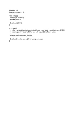
  • 1. int motor = 9; int potenciometer = 5; void setup(){ pinMode(9,OUTPUT); pinMode(5,INPUT); Serial.begin(9600); } void loop(){ int value = analogRead(potenciometer);//read input value: range between (0,1023) int motor_speed = value/4;//PWM can only ouput 255 different values analogWrite(motor,motor_speed); Serial.println(motor_speed);//for testing purposes }