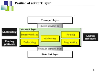
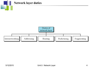
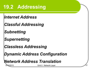
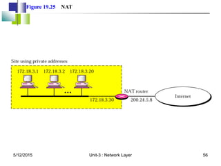
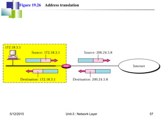
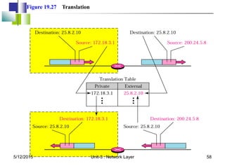
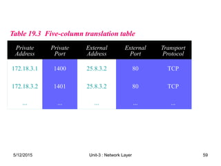
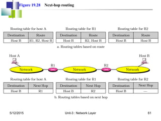
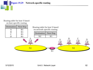
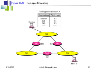
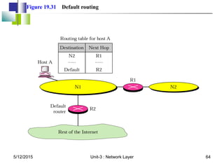
The document covers the network layer in computer networks, detailing its functions such as host-to-host delivery, addressing, and routing. It explains various addressing methods, including classful and classless addressing, as well as dynamic address configuration and network address translation. Additionally, it discusses routing techniques, including static and dynamic routing, with examples to illustrate the processes involved.


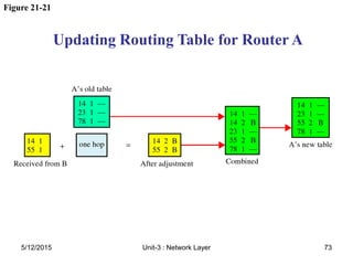
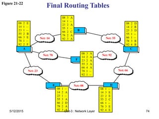
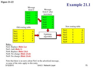
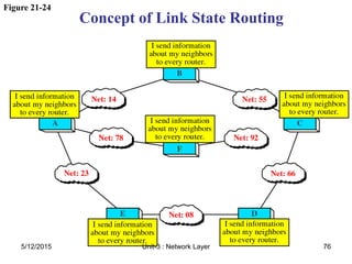

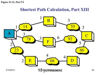
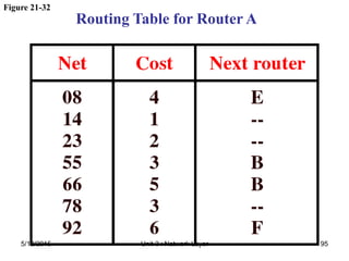


![[Ccna] subnetting & vlsm](https://cdn.slidesharecdn.com/ss_thumbnails/ccnasubnettingvlsm-100830021632-phpapp02-thumbnail.jpg?width=640&height=640&fit=bounds)