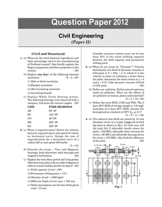
1. The document contains a sample question paper for a Civil Engineering exam with 6 questions covering topics like hydrology, geotechnical engineering, transportation engineering, structural analysis, and hydraulics.
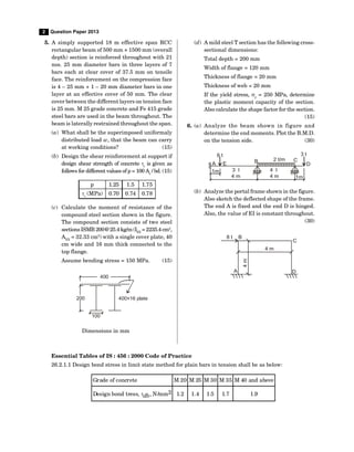
2. Question 1 has 4 parts asking about dissolved oxygen calculations, consolidation settlement, factors affecting duty of water, and sight distance.
3. Question 2 covers requirements of good ballast, traverse computations, and factors affecting contour intervals.
![SECTION – I
(Civil)
1. Differentiate between the following materials
giving specific uses in the building industry:
(6 + 8 + 8 + 8)
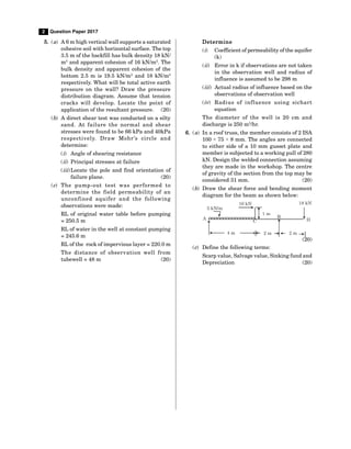
(a) Igneous, sedimentary and metamorphic rocks
(b) Bitumen, coal tar and asphalt
(c) Common burnt clay bricks, firebircks and
flyash bricks
(d) Paints and varnish
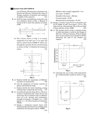
2. (a) A river is flowing from West to East. For
determining the width of the river, two points
A and B are selected on the southern bank
such that the distance AB = 75 m. Point A is
Westward. The bearings of a tree C on the
Northern bank are observed to be 38° and
338°, respectively from A and B. Calculate
the width of the river. (20)
(b) What are contour gradients? Explain their
importance in the location of a hill road. (10)
3. (a) A 10 m thick bed of sand is underlain by a
layer of clay 6 m thick. The water table that
was originally at ground level is lowered by
drainage to a depth 4 m, whereupon the
degree of saturation above lowered water
table reduces to 20%. Determine the increase
in the effective pressure at mid of clay layer
due to water table lowering. Given saturated
densities of sand and clay as 2.1 g/cm3
and
1.8 g/cm3
, and the dry density of sand = 1.7g/
cm3
.
Note : [g/cm3
= 103
kg/m3
× 9.8 m/s2
= 9.81
kN/m2
]. (20)
(b) An earth embankment is compacted at water
content of 17% to a bulk density of 1.9 g/cc.
If the sp. gr. of soil grains is 2.65 calculate
the void ratio of the compacted embankment.
(10)
4. (a) The space between two parallel horizontal
plates is kept 5 mm apart. This is filled with
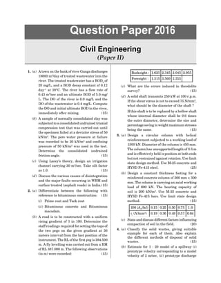
Question Paper 2007
Civil Engineering
(Paper II)
crude oil of dynamic viscosity 2.5 kg/m.s. If the
lower plate is stationary and the upper plate is
pulled with velocity of 1.75m/s, determine the
shear stress on the lower plate. (15)
(b) An open tank 5 m long, 2 m deep and 3 m
wide contains oil of relative density 0.9 to a
depth of 0.9 m. If the tank is accelerated along
its length on a horizontal track at a constant
value of 3 m/s2
, determine the new position
of oil surface. (15)
5. (a) Calculate the diameter and discharge of a
circular sewer laid at a slope of 1 in 400,
running half-full and with velocity 1.9 m/s (n
= 0.012). (15)
(b) The 5-day BOD of a waste is 280 mg/l. The
ultimate BOD is reported to be 410 mg/l. At
what rate the waste is being oxidised? (15)
6. (a) What are the various methods of doing
theodolite traversing? Describe the deflection
angle method in detail. (10)
(b) What soil investigations are required for
constructing (i) an embankment and (ii) a
building? Give details. (10)
(c) Write a note on flow measurement methods
employed for pipe flow and open channels
(with specific reference to drains). (10)
SECTION – II
(Structural)
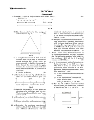
7. (a) Draw SF and BM diagrams for the beam with
applied moment as shown in Fig. 1. (15)
a b
x
R = M/L
B
R = M/
A l
C
A M B
Fig. 1
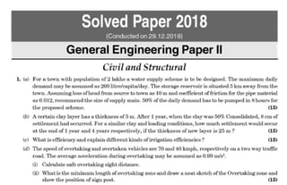
(b) A bar 40 mm in diameter is subjected to a
tensile force of 40000 kg. The extension of
bar measured over a gauge length of 200 mm](https://image.slidesharecdn.com/civil-paper-ii-230415034139-3e5e8b64/85/Civil-Paper-II-pdf-41-320.jpg)