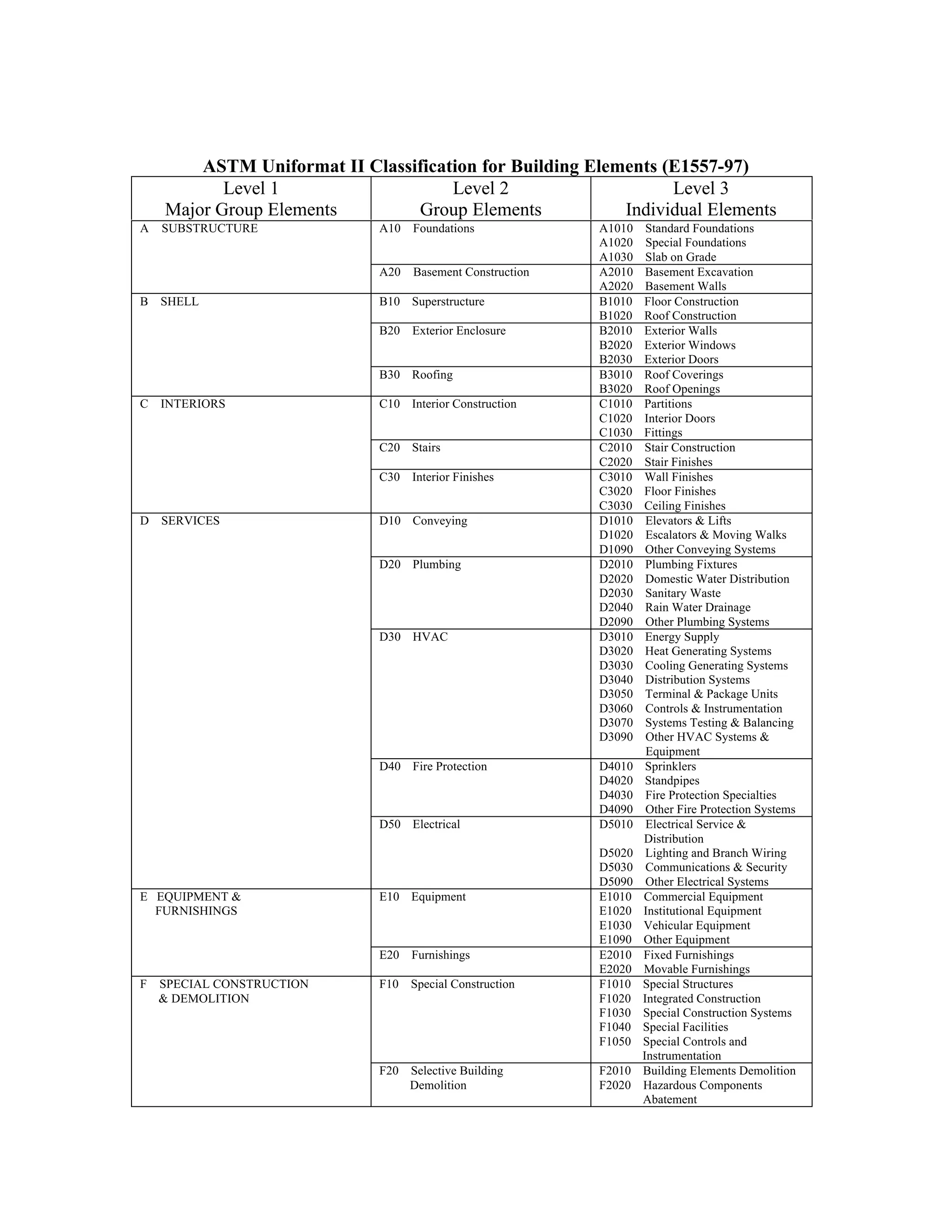
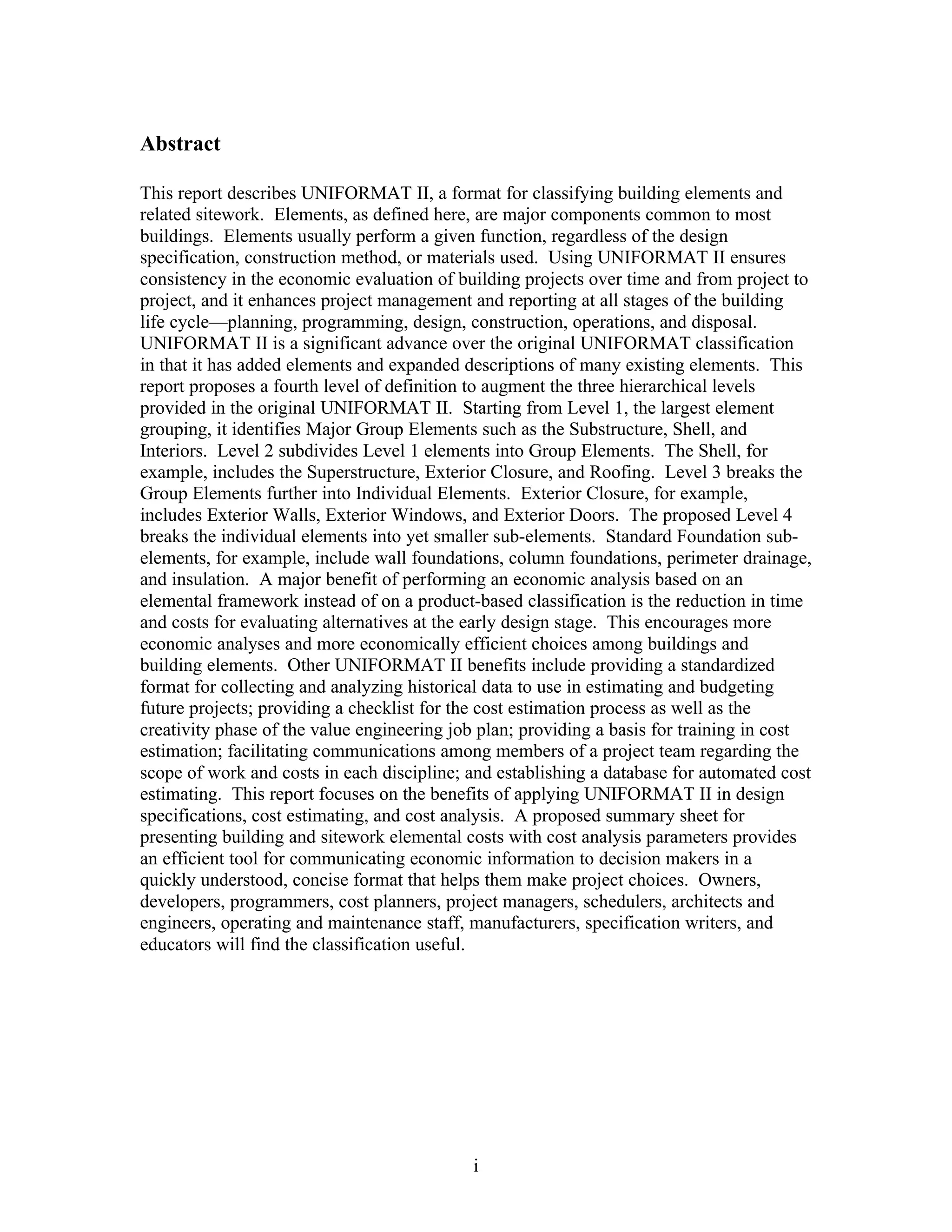
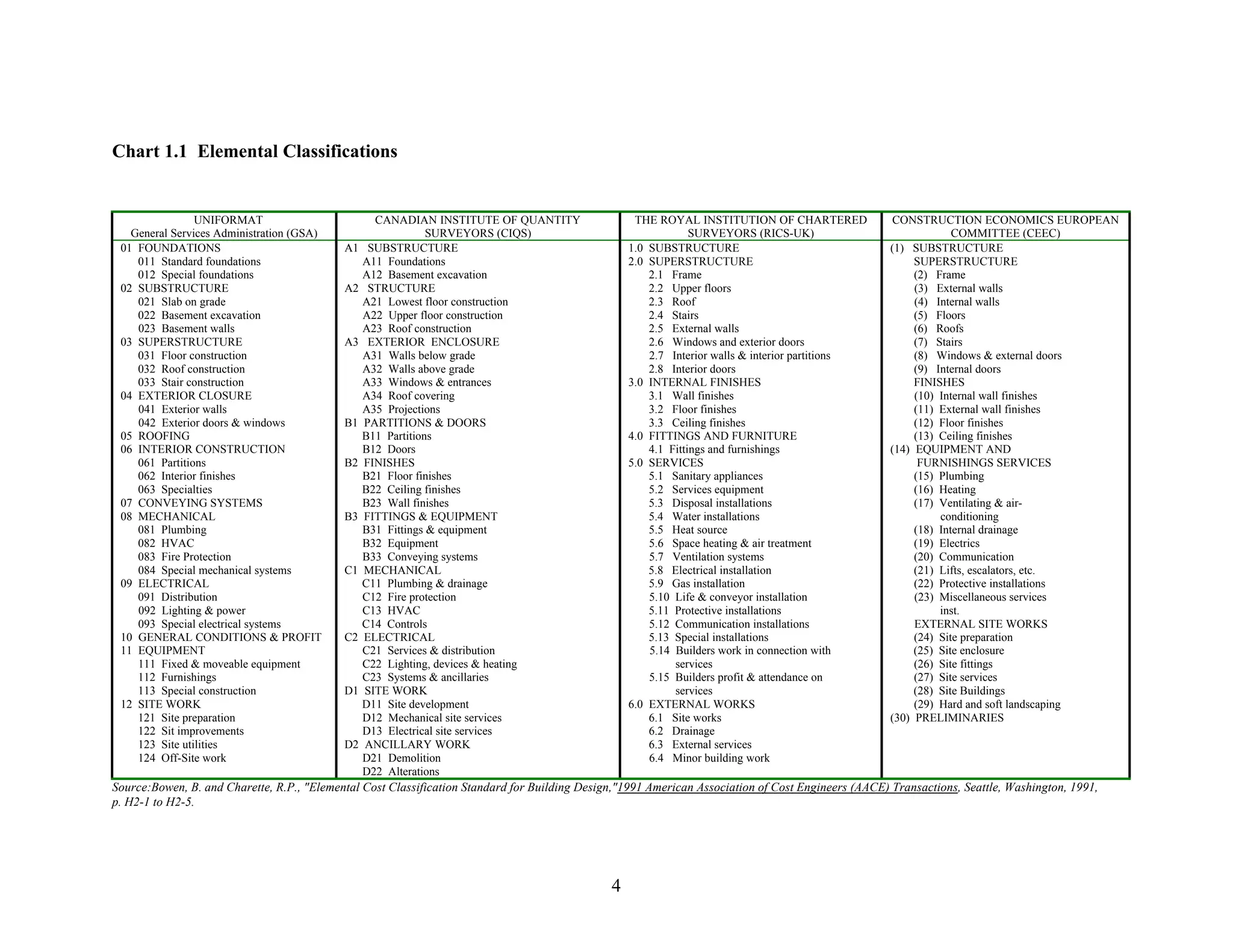
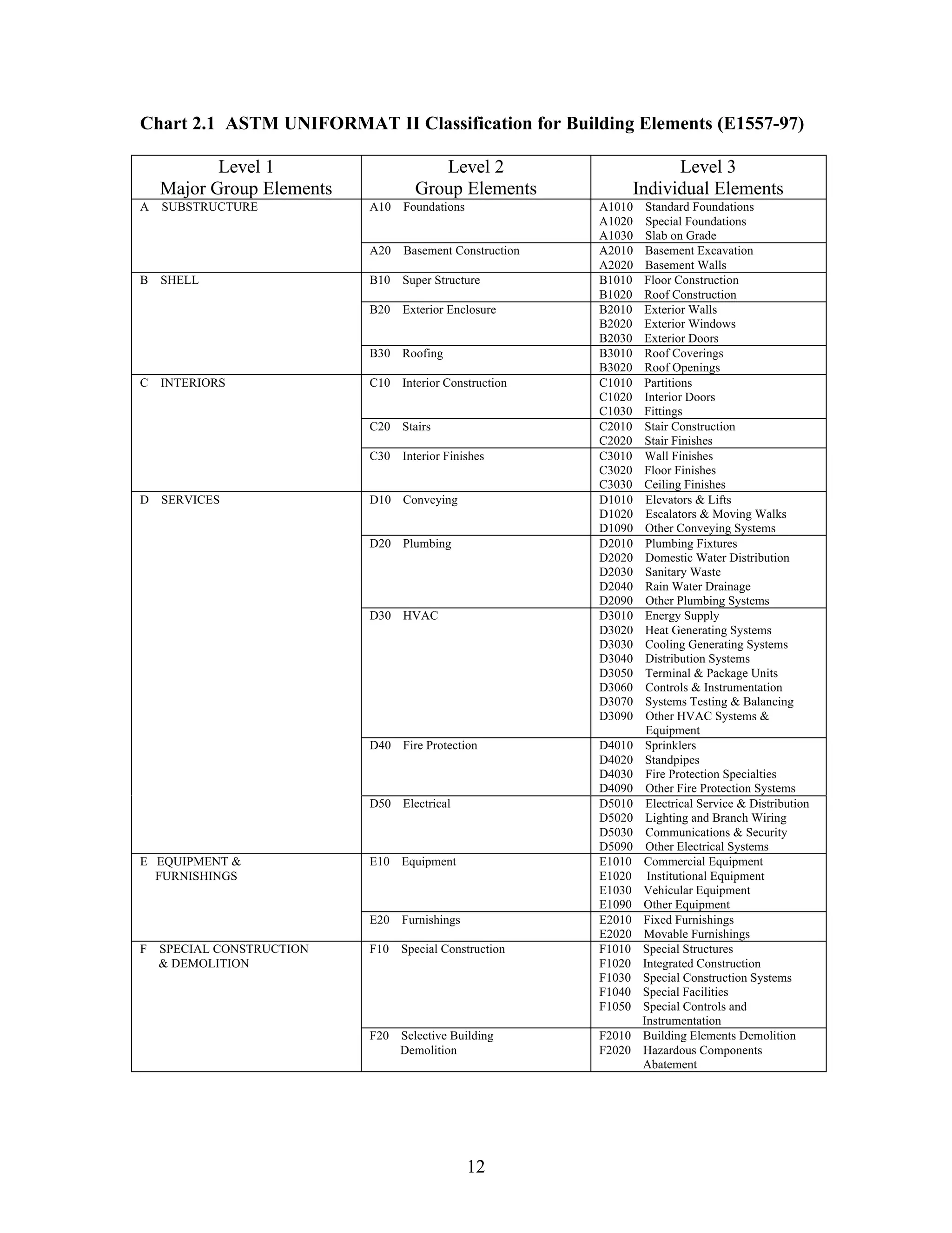
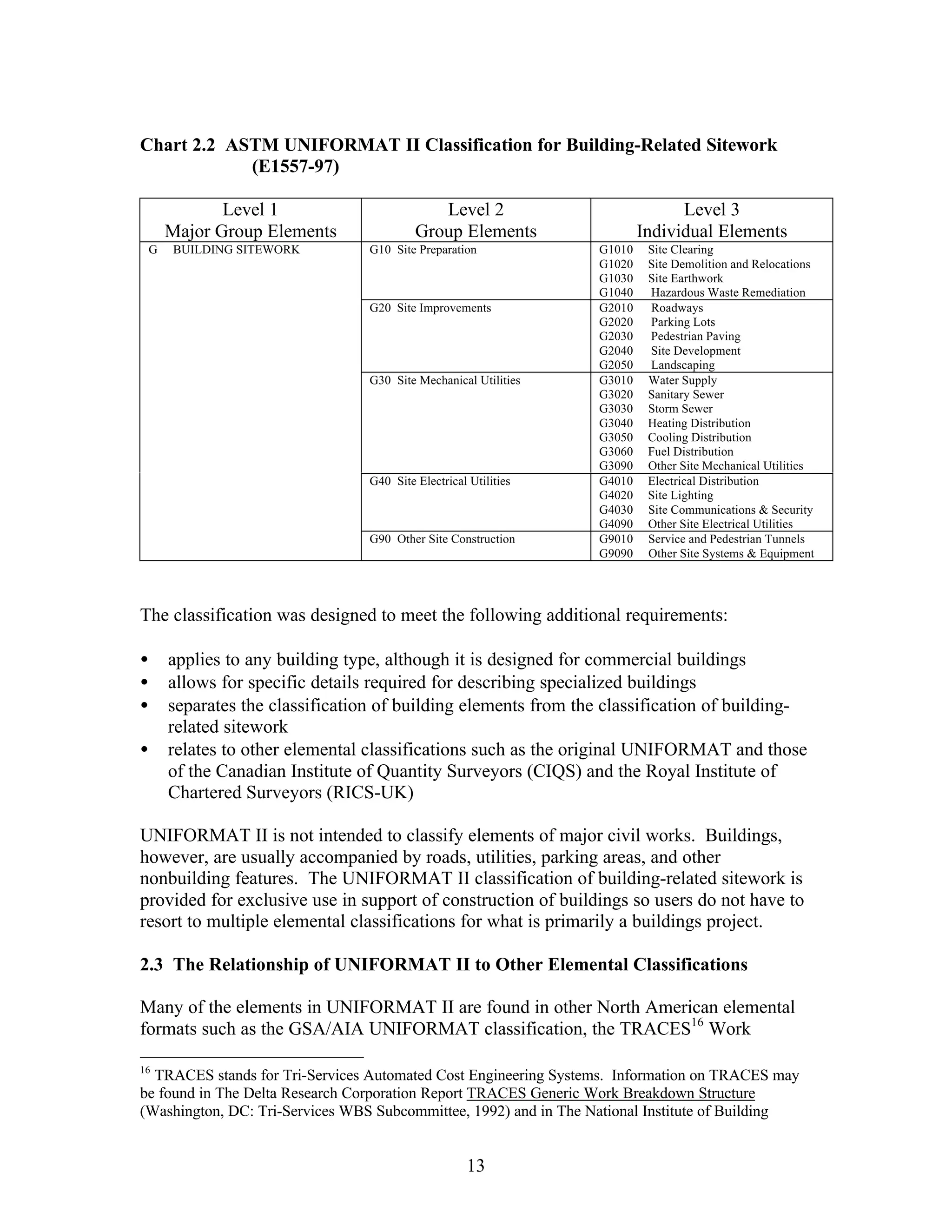
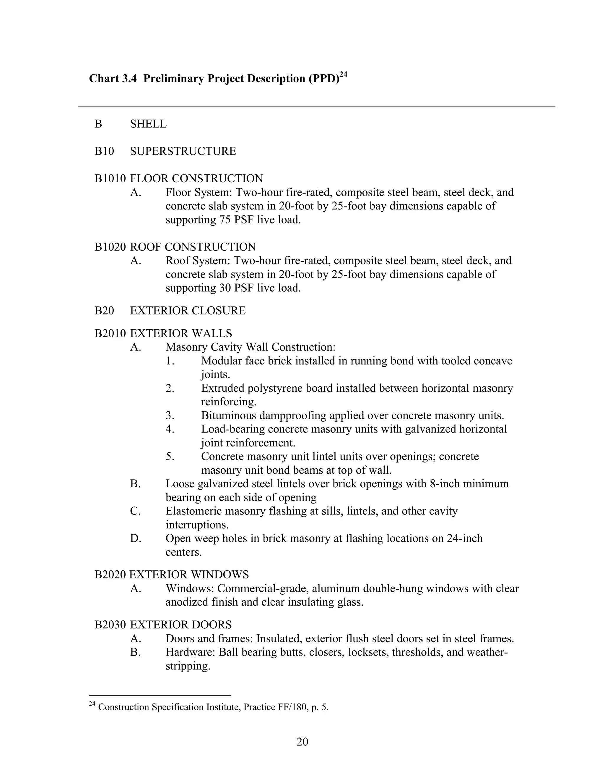
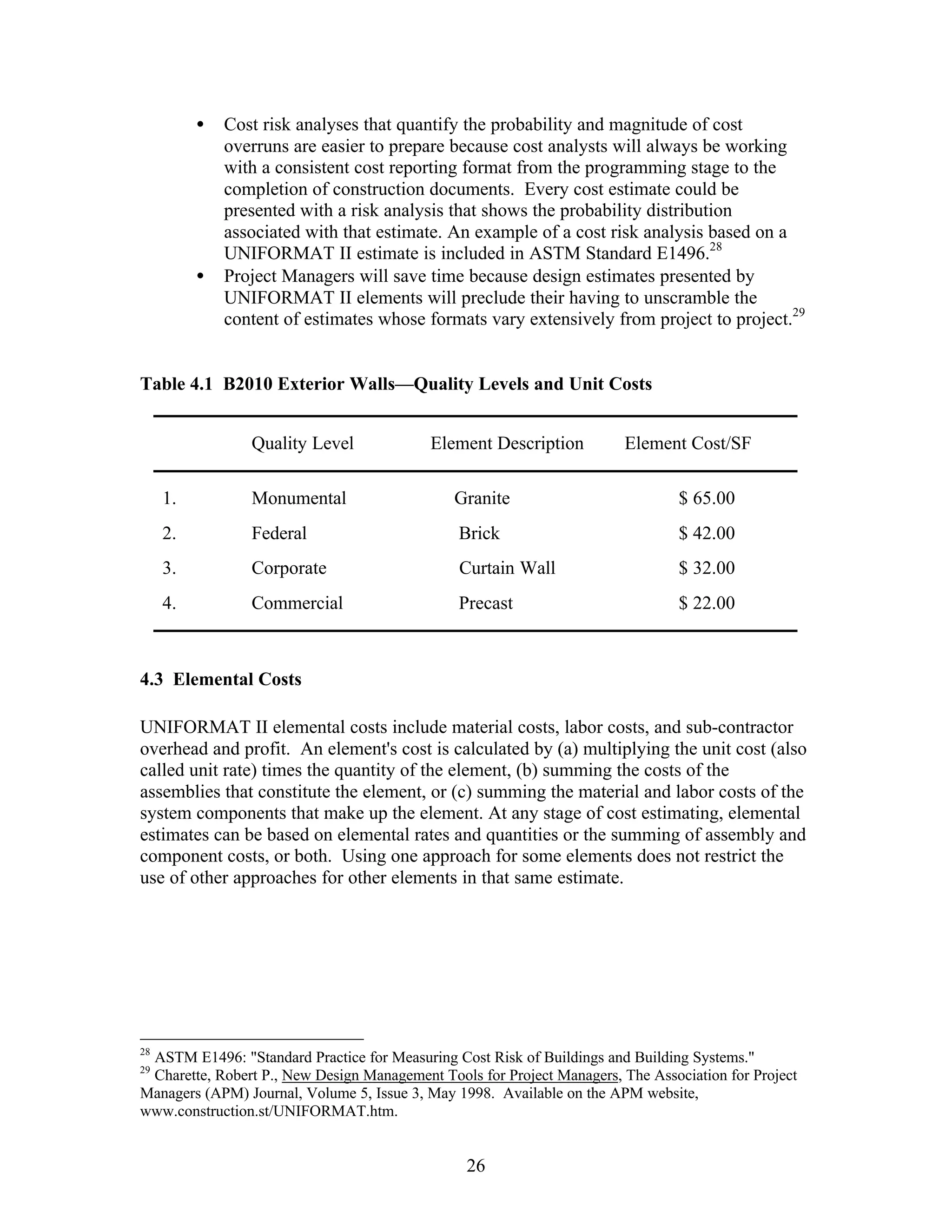
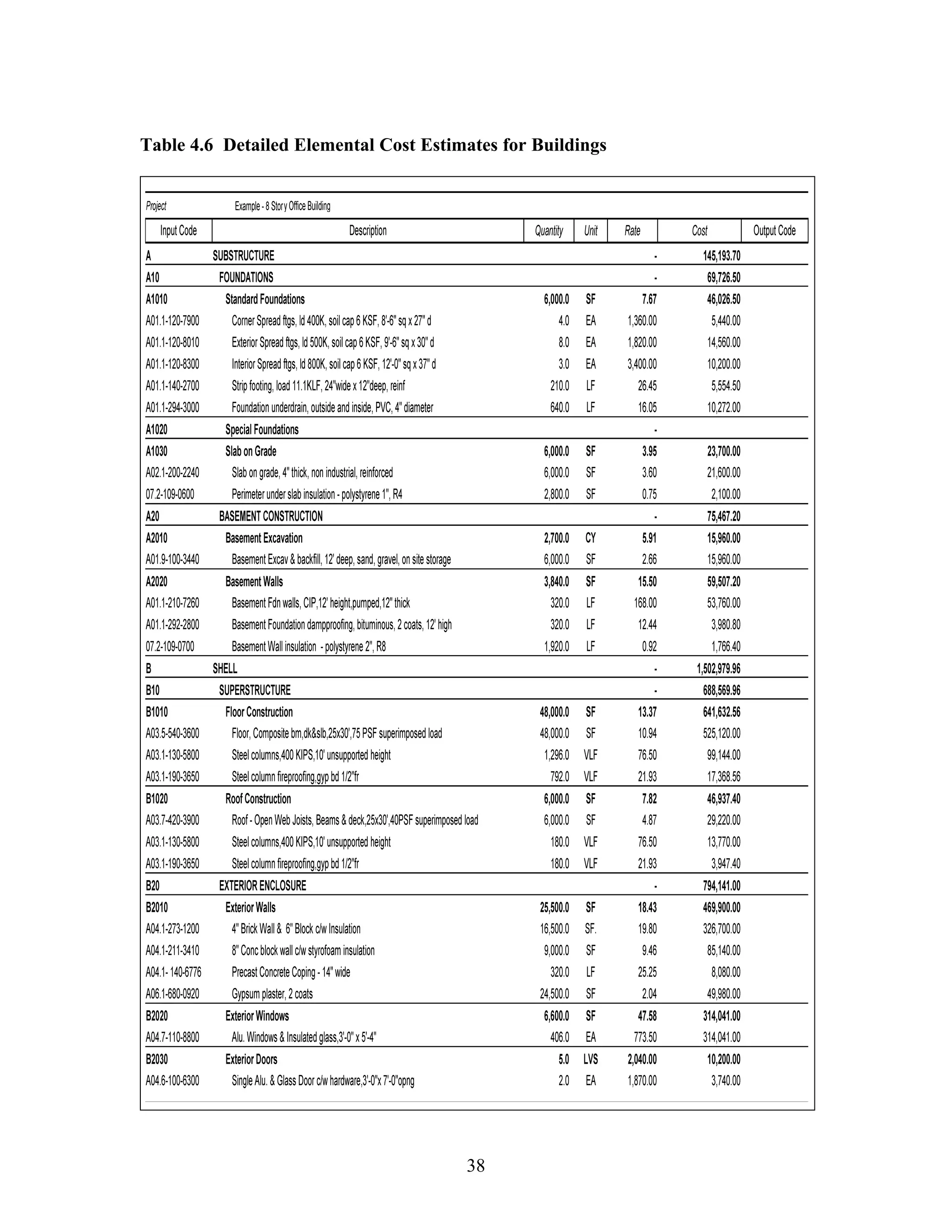
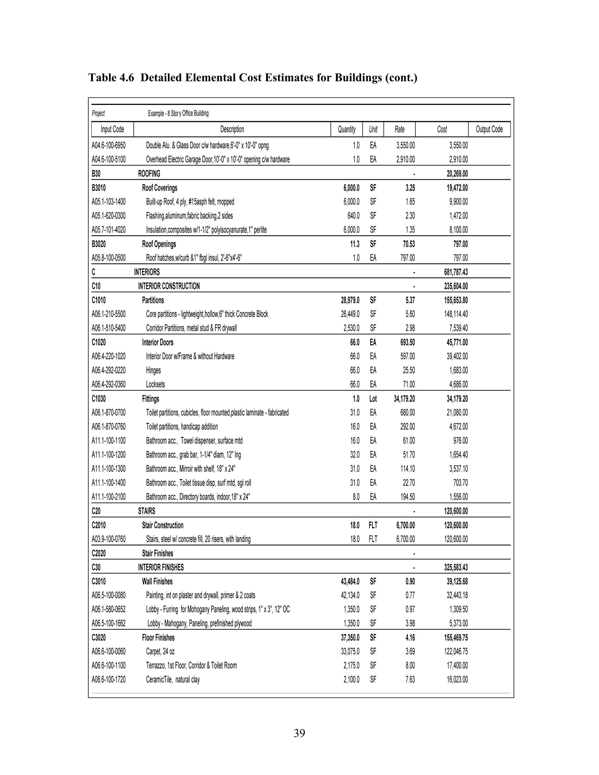
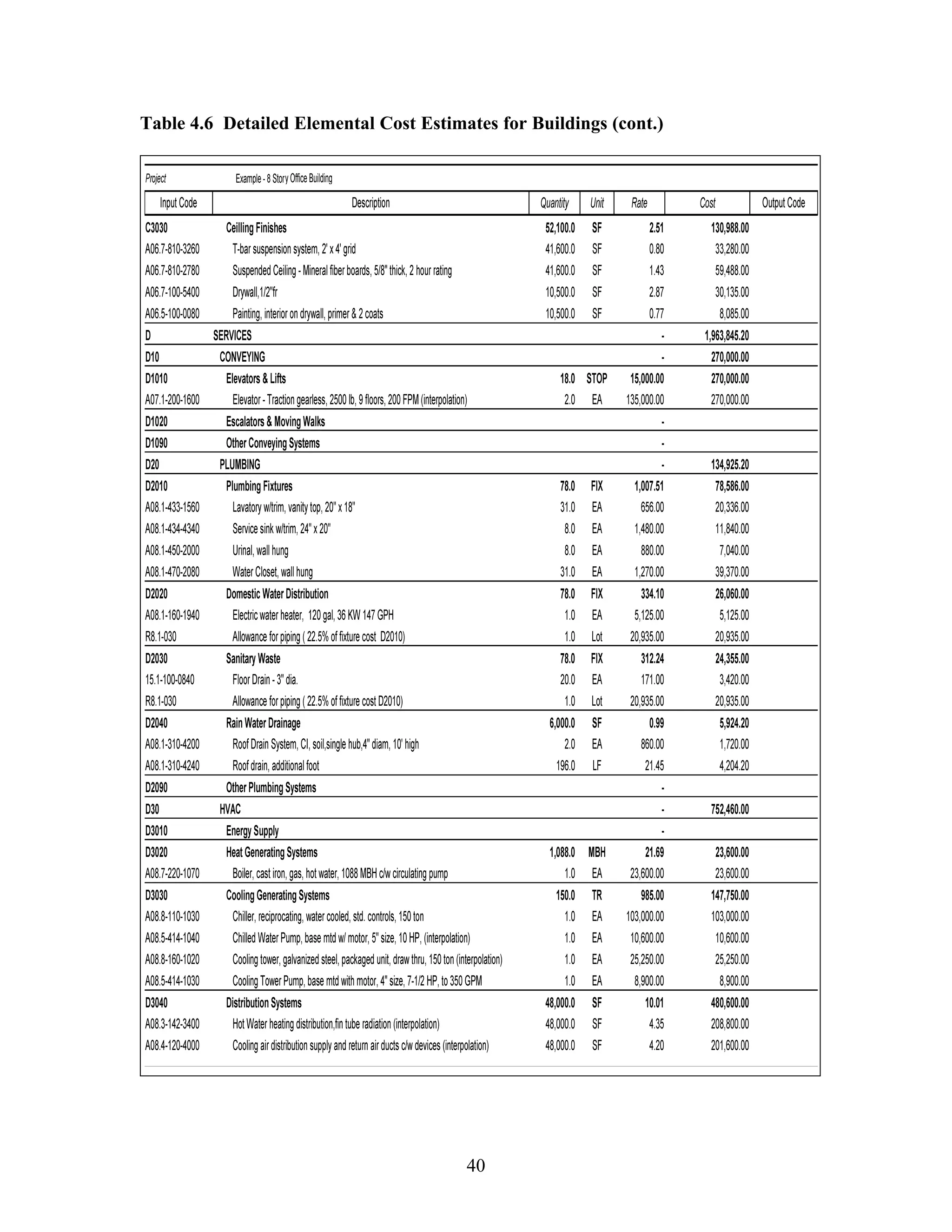
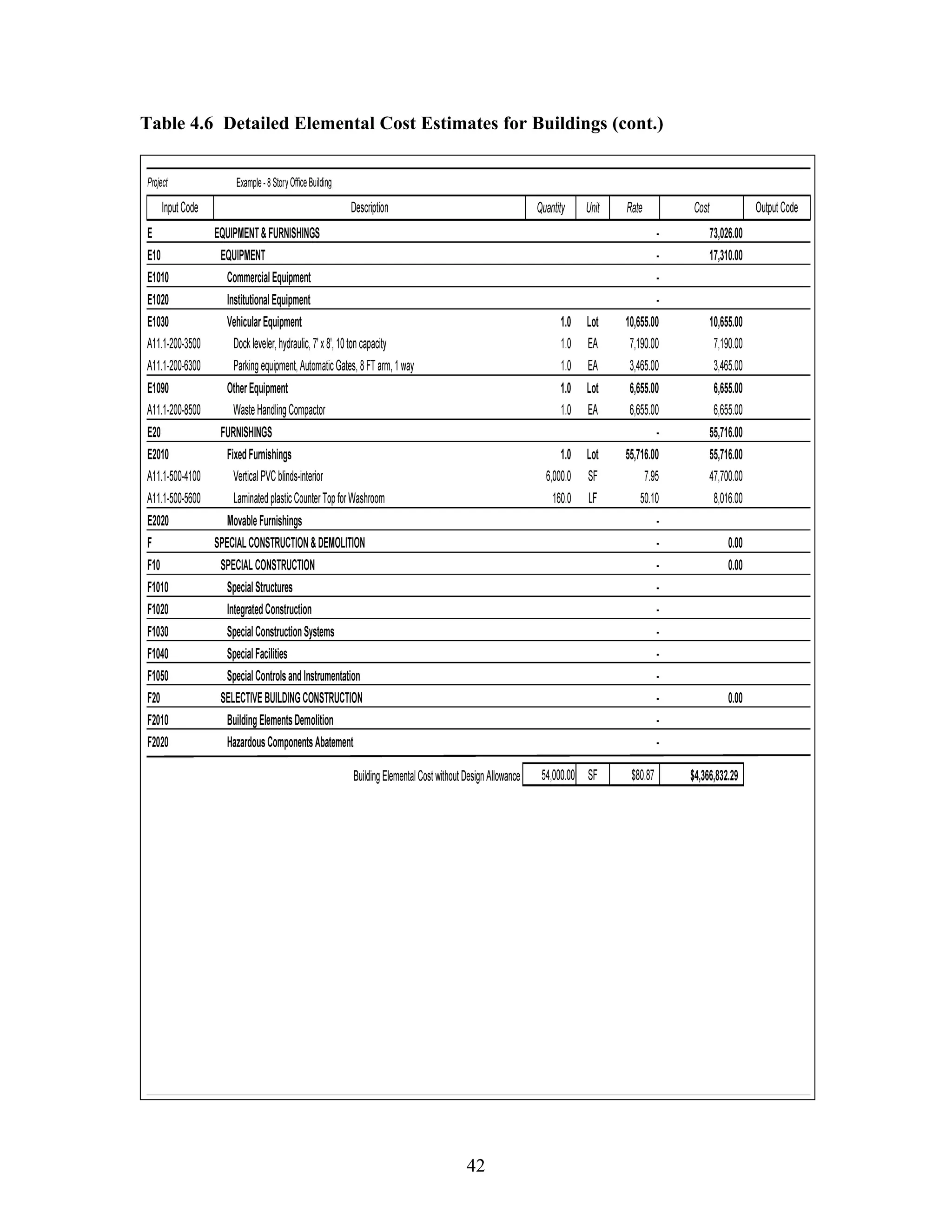
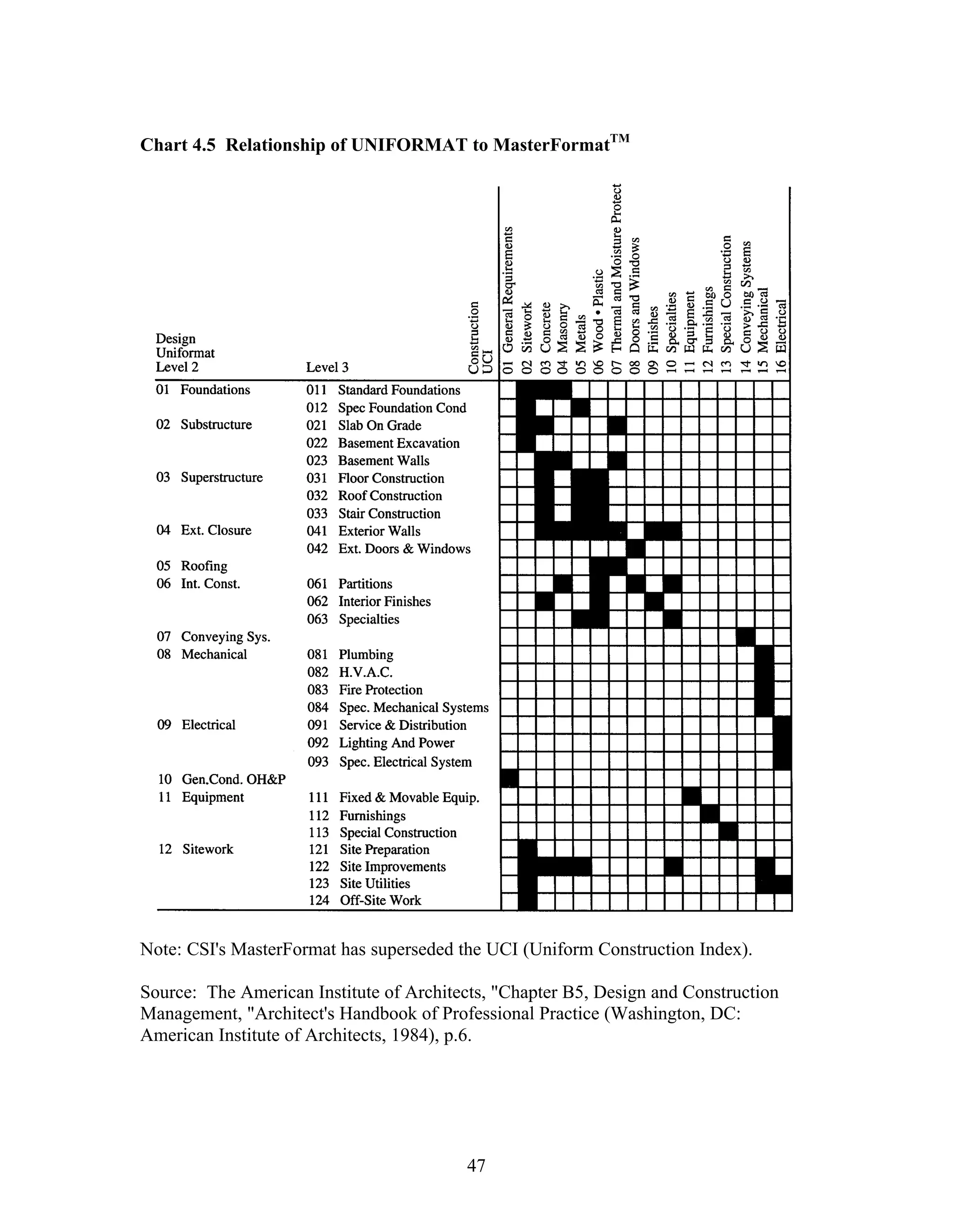
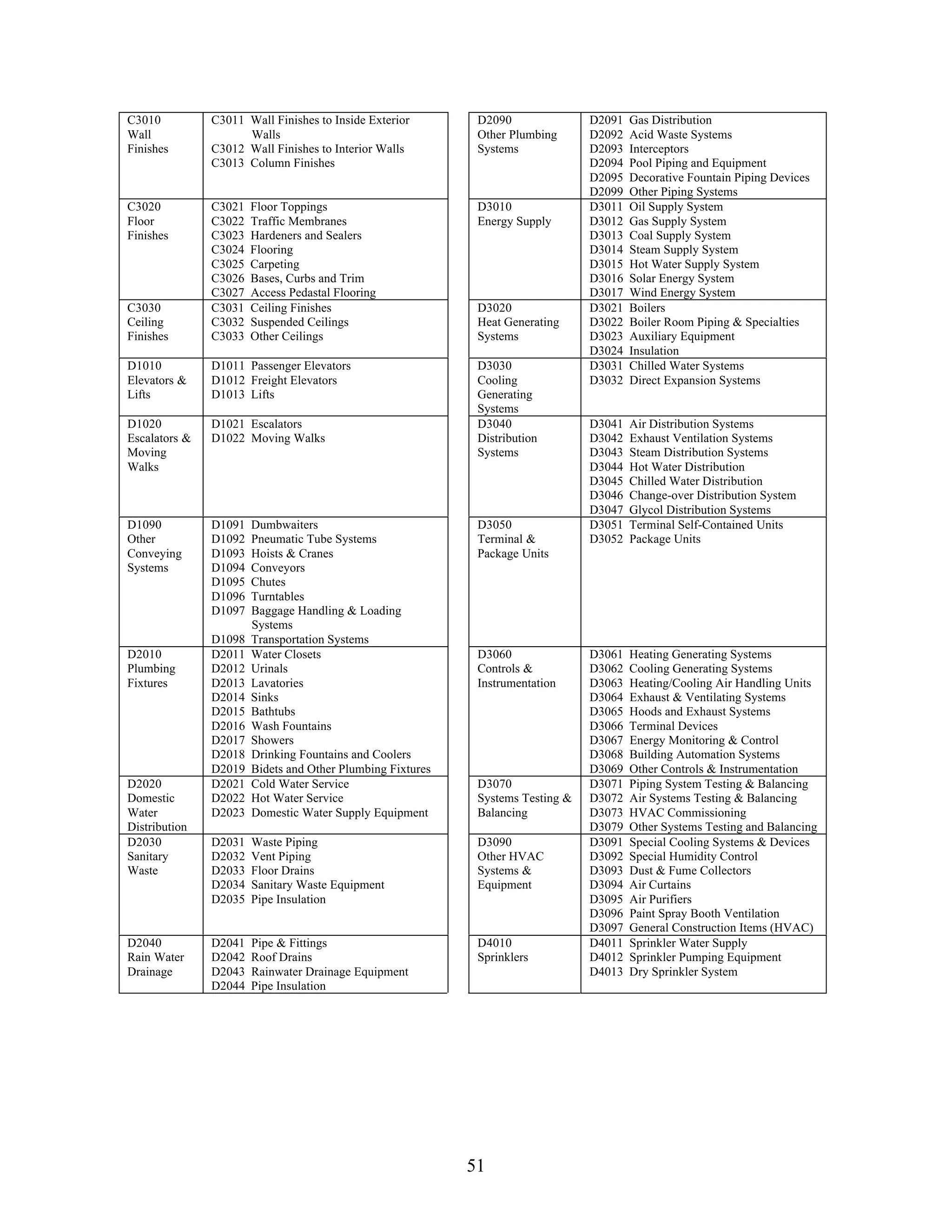
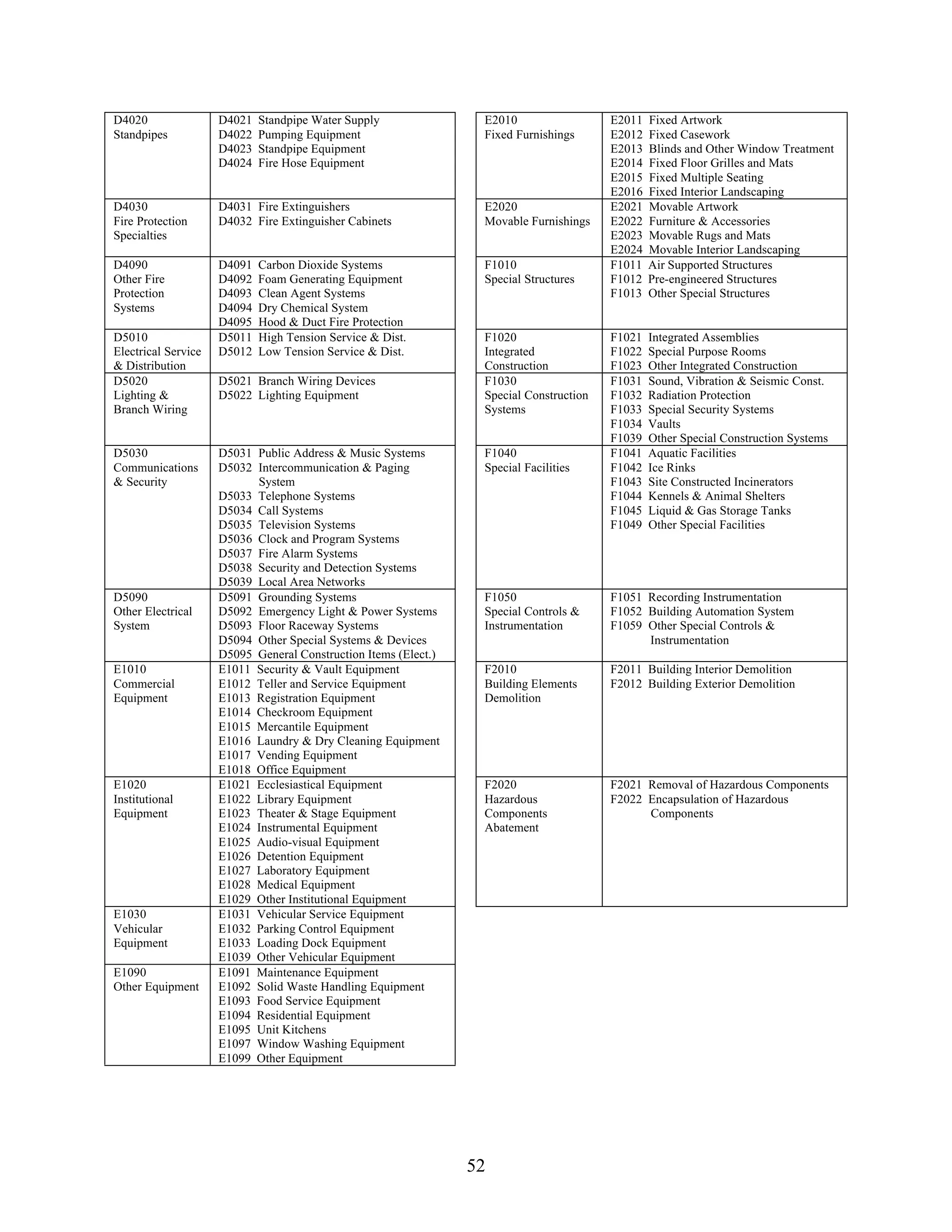
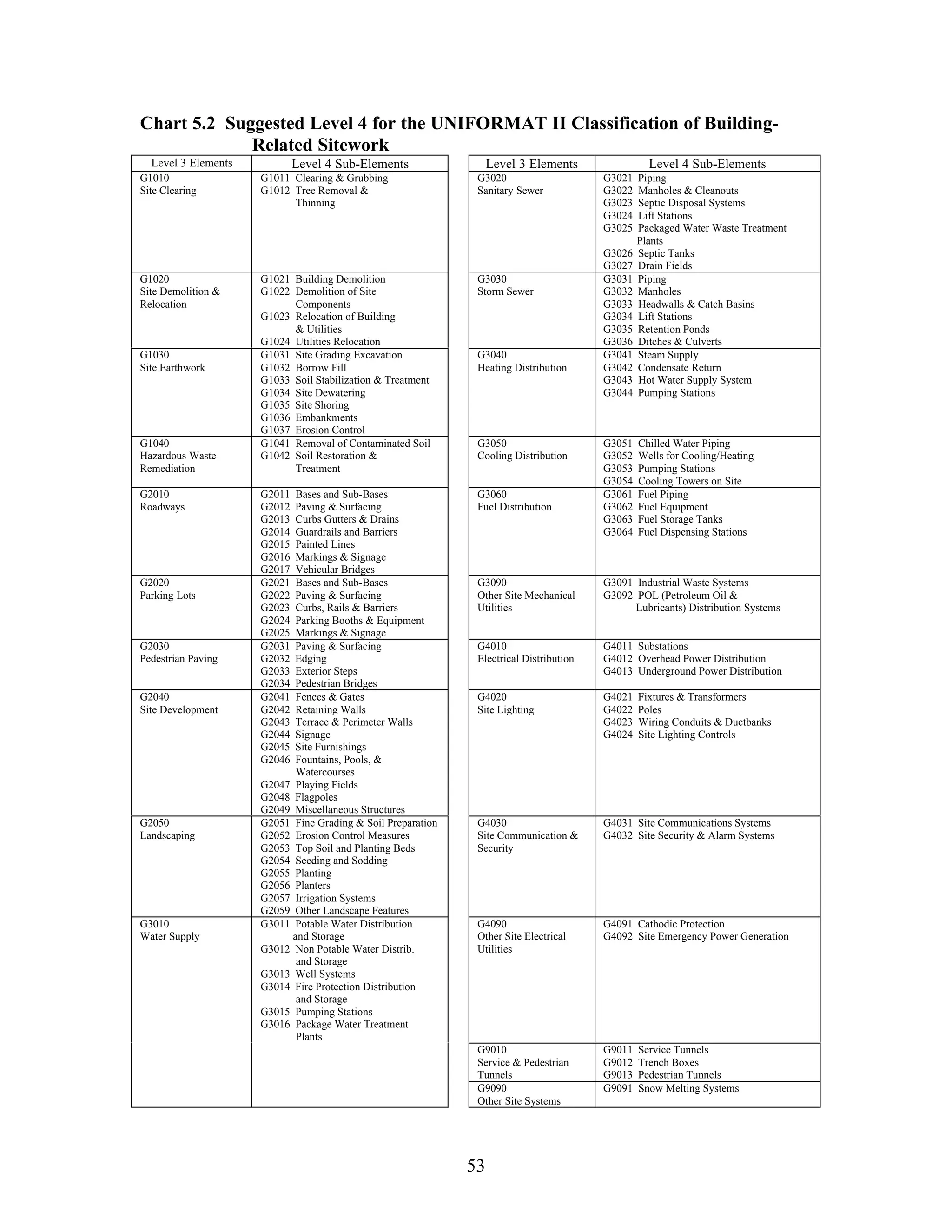
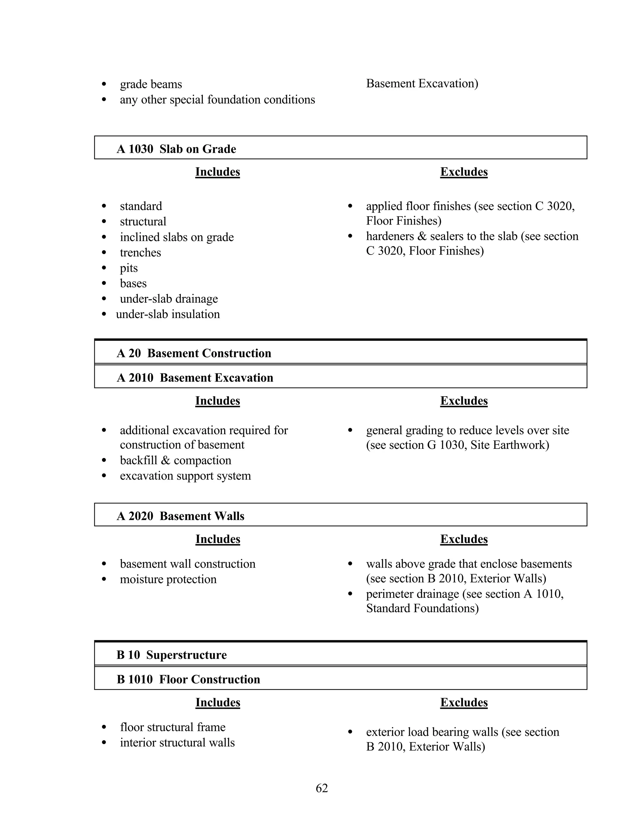
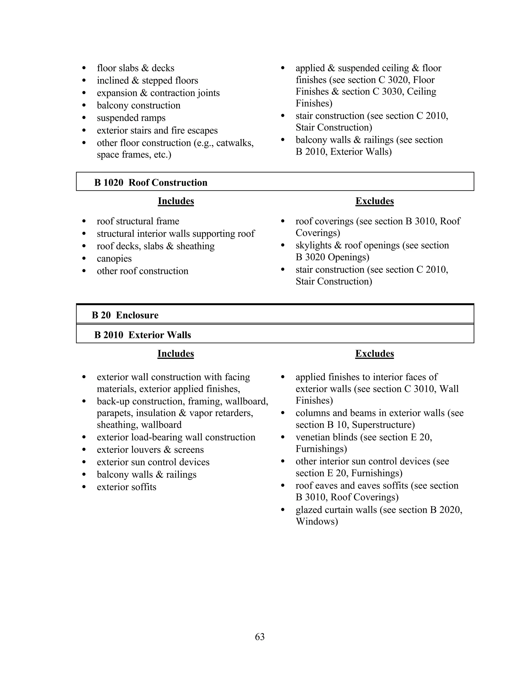
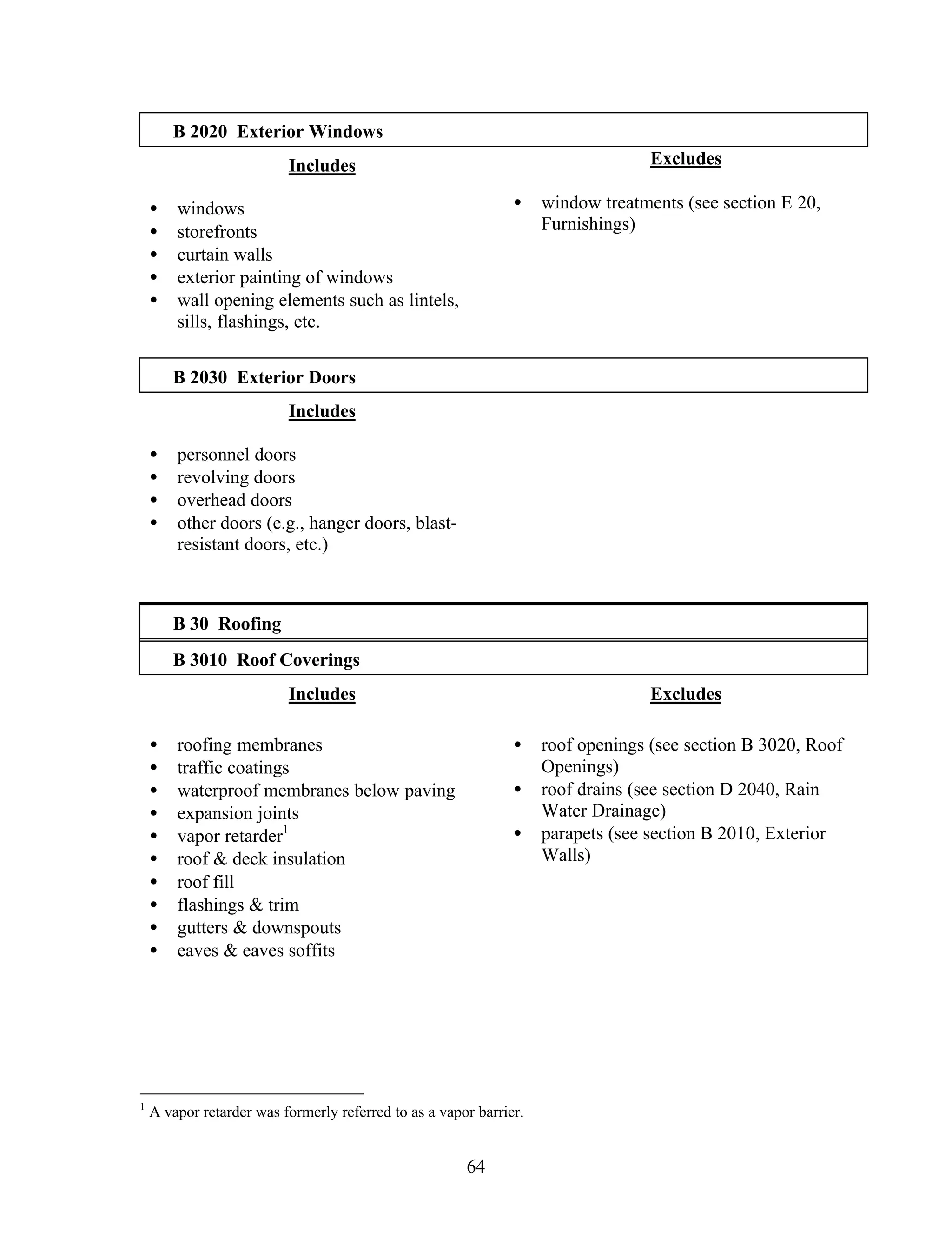
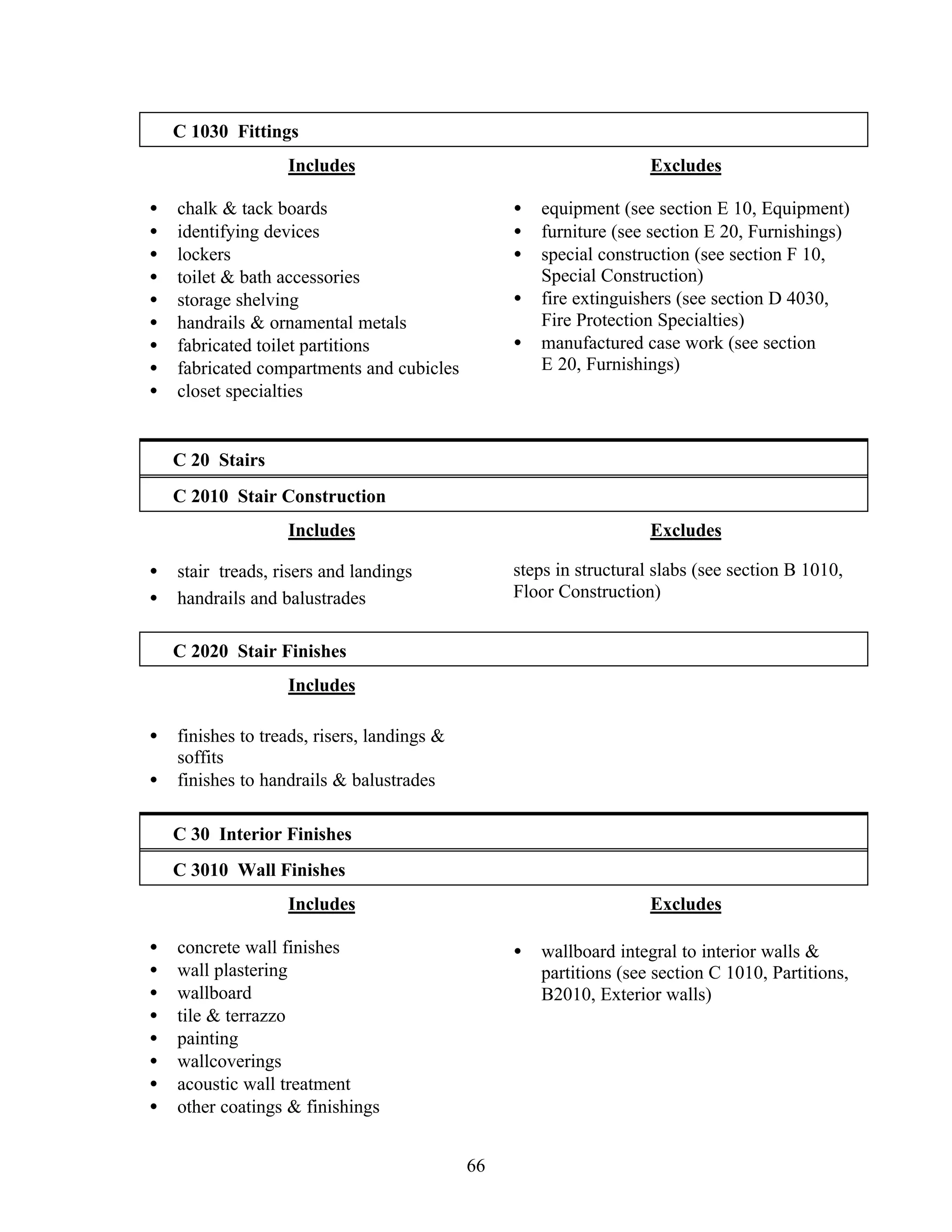
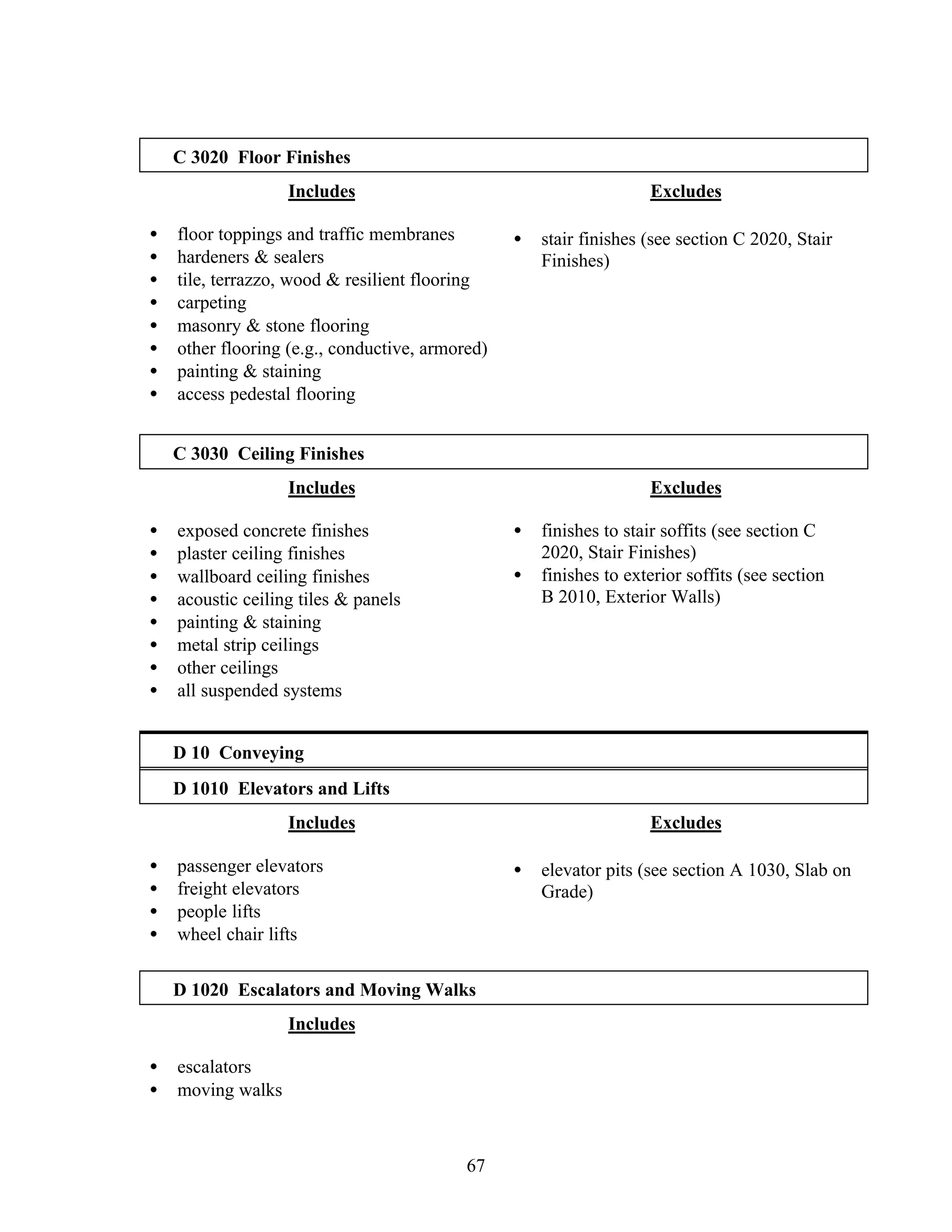
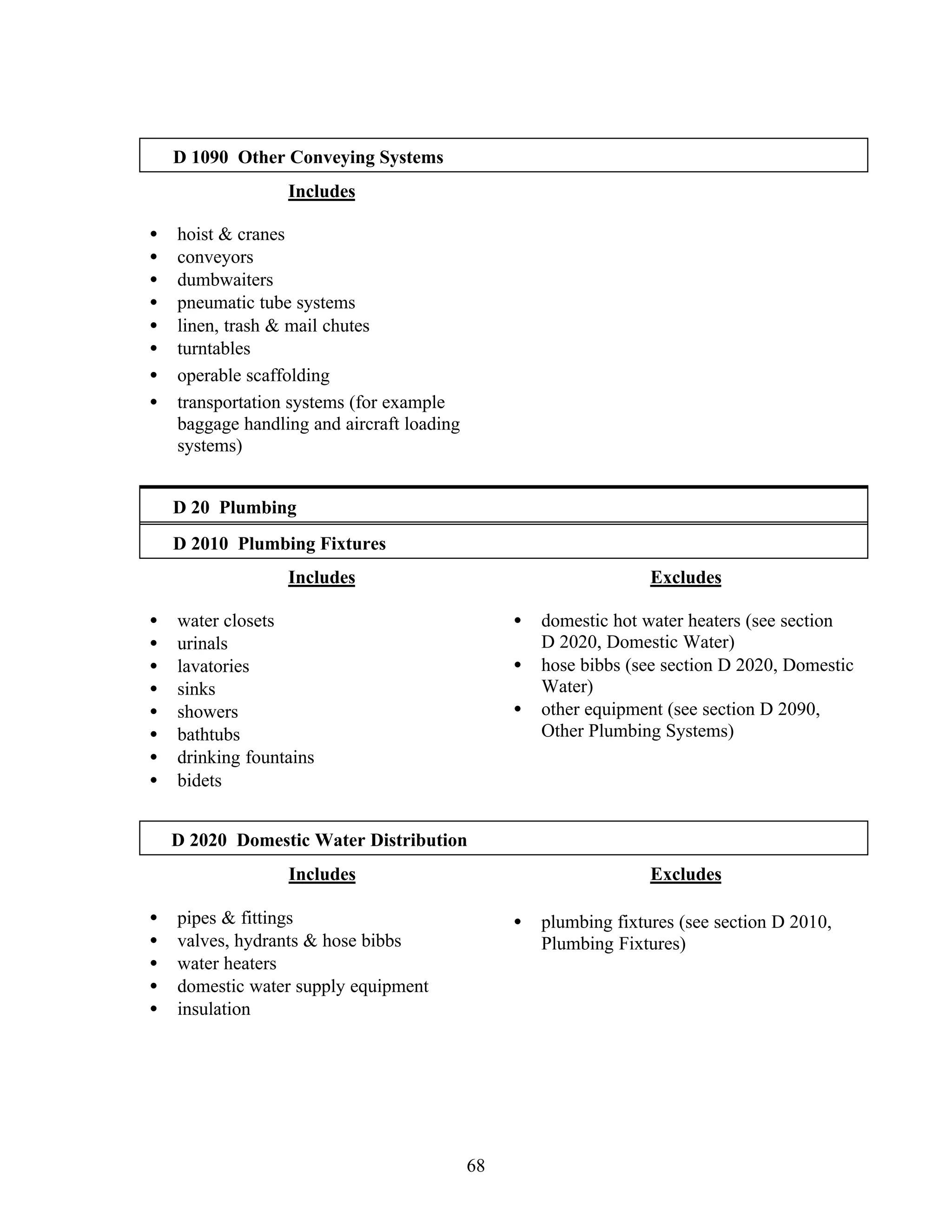
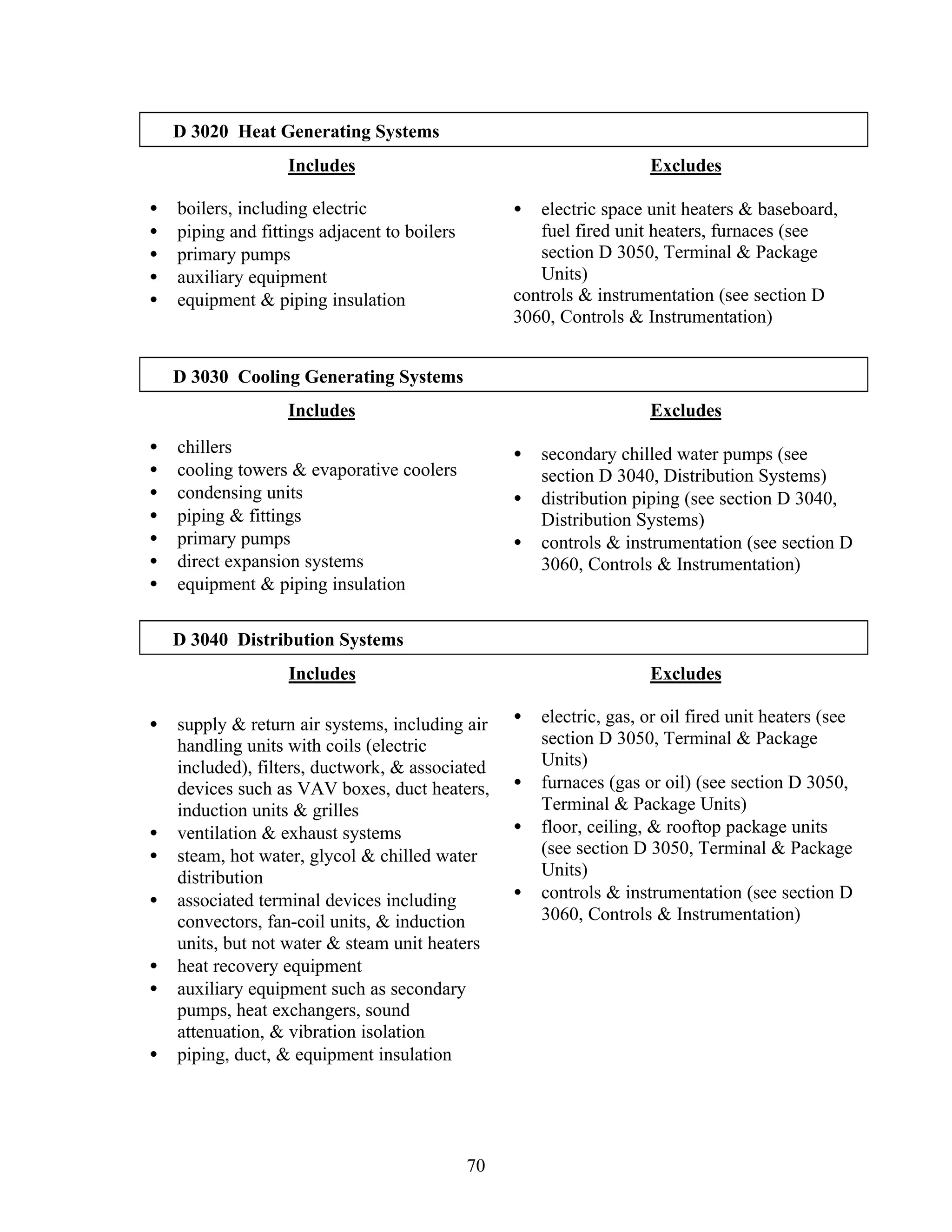
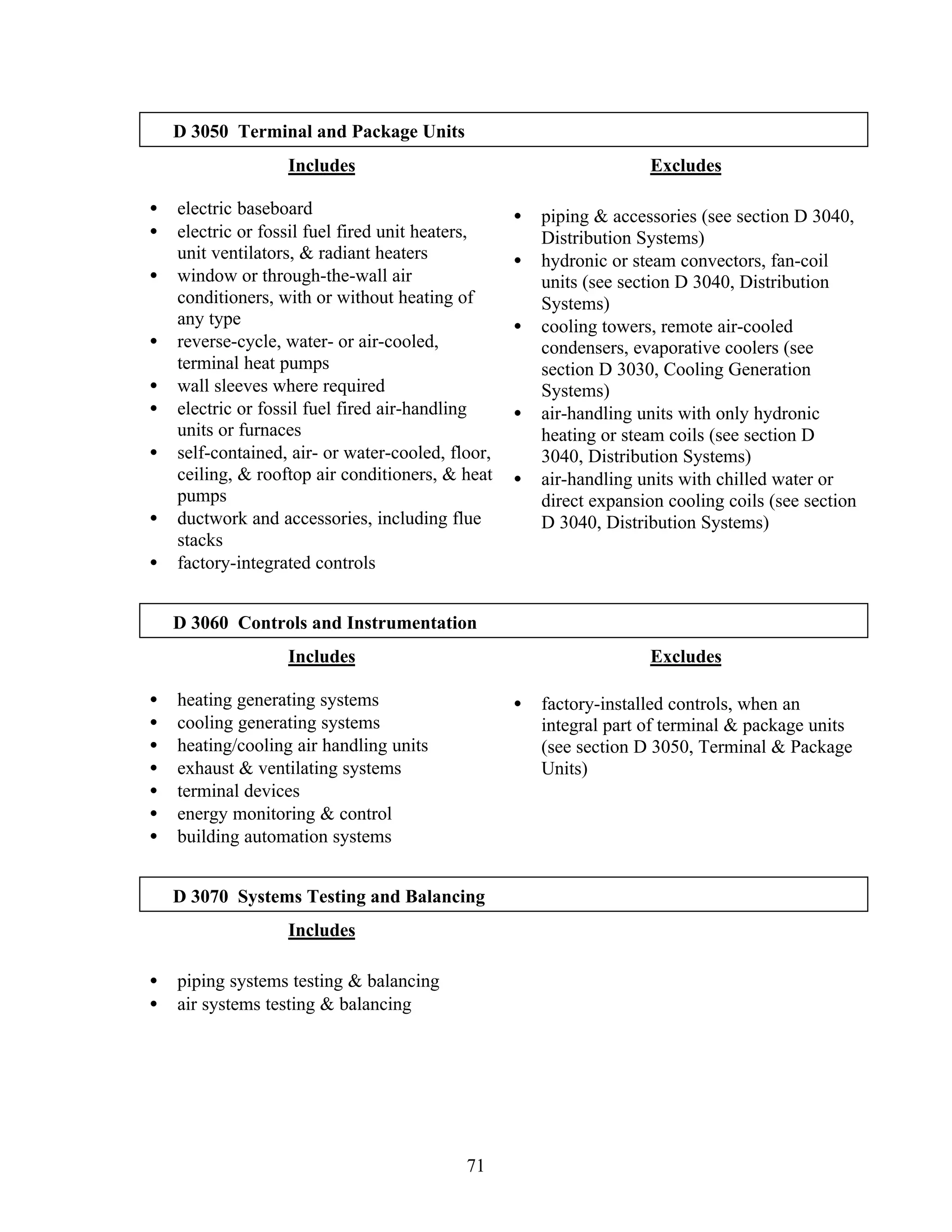
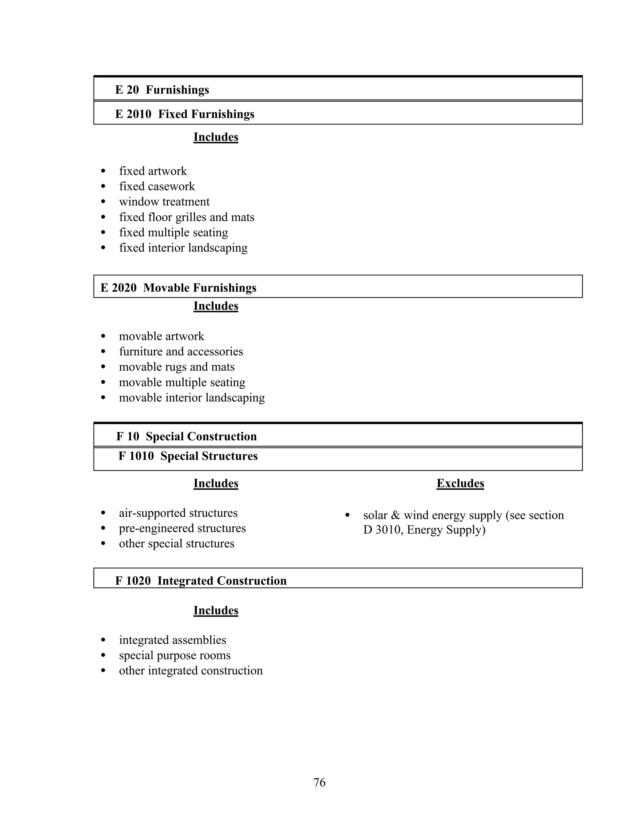
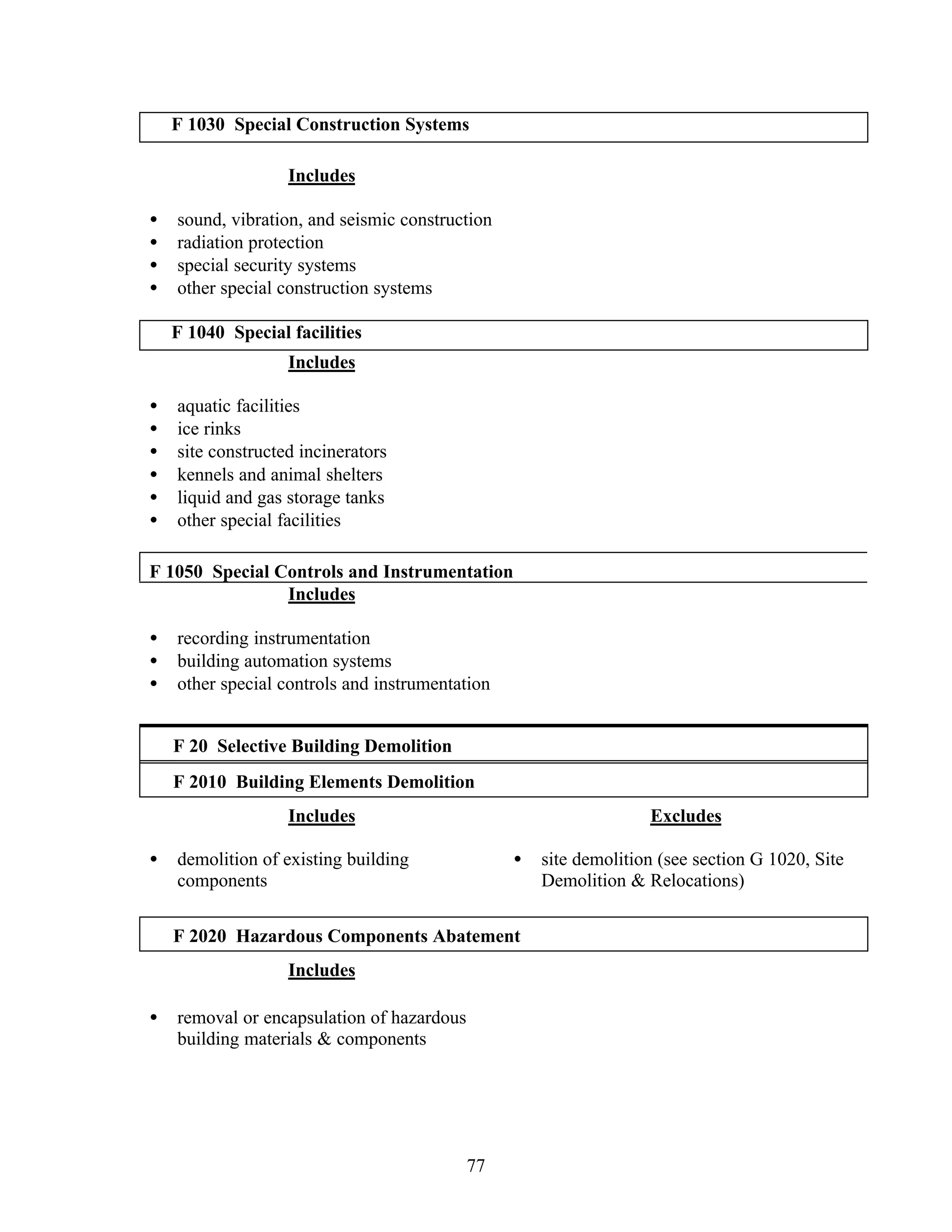
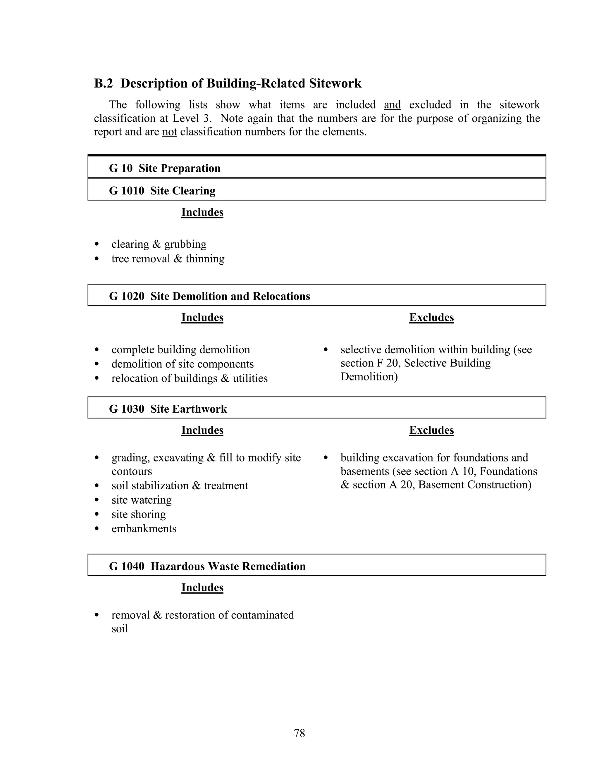
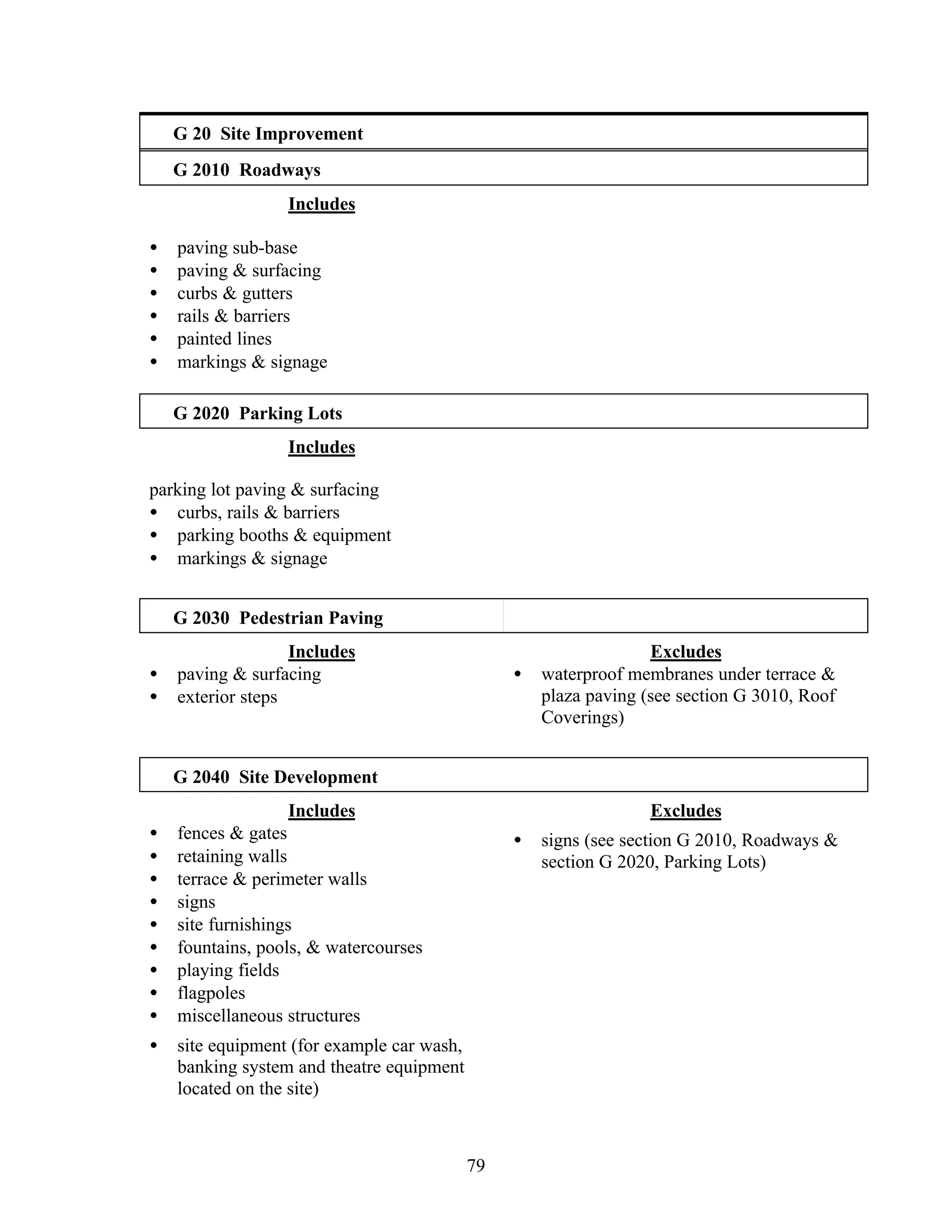
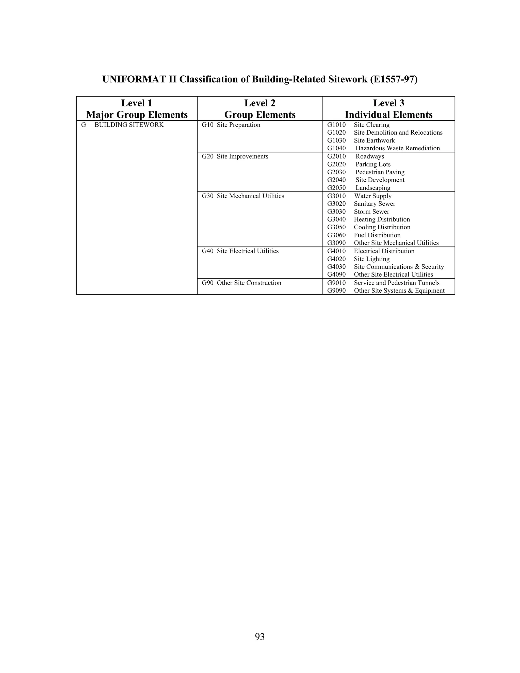
U.S. DEPARTMENT OF COMMERCE
Technology Administration
National Institute of Standards and Technology
NISTIR 6389
UNIFORMAT II Elemental Classification
for Building Specifications, Cost
Estimating, and Cost Analysis
Robert P. Charette
Harold E. Marshall
ASTM Uniformat II Classification for Building Elements (E1557-97)
Level 1
Major Group Elements
Level 2
Group Elements
Level 3
Individual Elements
A10 Foundations A1010 Standard Foundations
A1020 Special Foundations
A1030 Slab on Grade
A SUBSTRUCTURE
A20 Basement Construction A2010 Basement Excavation
A2020 Basement Walls
B10 Superstructure B1010 Floor Construction
B1020 Roof Construction
B20 Exterior Enclosure B2010 Exterior Walls
B2020 Exterior Windows
B2030 Exterior Doors
B SHELL
B30 Roofing B3010 Roof Coverings
B3020 Roof Openings
C10 Interior Construction C1010 Partitions
C1020 Interior Doors
C1030 Fittings
C20 Stairs C2010 Stair Construction
C2020 Stair Finishes
C INTERIORS
C30 Interior Finishes C3010 Wall Finishes
C3020 Floor Finishes
C3030 Ceiling Finishes
D10 Conveying D1010 Elevators & Lifts
D1020 Escalators & Moving Walks
D1090 Other Conveying Systems
D20 Plumbing D2010 Plumbing Fixtures
D2020 Domestic Water Distribution
D2030 Sanitary Waste
D2040 Rain Water Drainage
D2090 Other Plumbing Systems
D30 HVAC D3010 Energy Supply
D3020 Heat Generating Systems
D3030 Cooling Generating Systems
D3040 Distribution Systems
D3050 Terminal & Package Units
D3060 Controls & Instrumentation
D3070 Systems Testing & Balancing
D3090 Other HVAC Systems &
Equipment
D40 Fire Protection D4010 Sprinklers
D4020 Standpipes
D4030 Fire Protection Specialties
D4090 Other Fire Protection Systems
D SERVICES
D50 Electrical D5010 Electrical Service &
Distribution
D5020 Lighting and Branch Wiring
D5030 Communications & Security
D5090 Other Electrical Systems
E10 Equipment E1010 Commercial Equipment
E1020 Institutional Equipment
E1030 Vehicular Equipment
E1090 Other Equipment
E EQUIPMENT &
FURNISHINGS
E20 Furnishings E2010 Fixed Furnishings
E2020 Movable Furnishings
F10 Special Construction F1010 Special Structures
F1020 Integrated Construction
F1030 Special Construction Systems
F1040 Special Facilities
F1050 Special Controls and
Instrumentation
F SPECIAL CONSTRUCTION
& DEMOLITION
F20 Selective Building
Demolition
F2010 Building Elements Demolition
F2020 Hazardous Components
Abatement
U.S. DEPARTMENT OF COMMERCE
Technology Administration
National Institute of Standards and Technology
NISTIR 6389
UNIFORMAT II Elemental Classification
for Building Specifications, Cost Estimating,
and Cost Analysis
Robert P. Charette
Concordia University
Montreal, Canada
and
Harold E. Marshall
Office of Applied Economics
Building and Fire Research Laboratory
National Institute of Standards and Technology
October 1999
U.S. DEPARTMENT OF COMMERCE
William M. Daley, Secretary
Technology Administration
Cheryl L. Shavers, Under Secretary for Technology
National Institute of Standards and Technology
Raymond G. Kammer, Director
i
Abstract
This report describes UNIFORMAT II, a format for classifying building elements and
related sitework. Elements, as defined here, are major components common to most
buildings. Elements usually perform a given function, regardless of the design
specification, construction method, or materials used. Using UNIFORMAT II ensures
consistency in the economic evaluation of building projects over time and from project to
project, and it enhances project management and reporting at all stages of the building
life cycle—planning, programming, design, construction, operations, and disposal.
UNIFORMAT II is a significant advance over the original UNIFORMAT classification
in that it has added elements and expanded descriptions of many existing elements. This
report proposes a fourth level of definition to augment the three hierarchical levels
provided in the original UNIFORMAT II. Starting from Level 1, the largest element
grouping, it identifies Major Group Elements such as the Substructure, Shell, and
Interiors. Level 2 subdivides Level 1 elements into Group Elements. The Shell, for
example, includes the Superstructure, Exterior Closure, and Roofing. Level 3 breaks the
Group Elements further into Individual Elements. Exterior Closure, for example,
includes Exterior Walls, Exterior Windows, and Exterior Doors. The proposed Level 4
breaks the individual elements into yet smaller sub-elements. Standard Foundation sub-
elements, for example, include wall foundations, column foundations, perimeter drainage,
and insulation. A major benefit of performing an economic analysis based on an
elemental framework instead of on a product-based classification is the reduction in time
and costs for evaluating alternatives at the early design stage. This encourages more
economic analyses and more economically efficient choices among buildings and
building elements. Other UNIFORMAT II benefits include providing a standardized
format for collecting and analyzing historical data to use in estimating and budgeting
future projects; providing a checklist for the cost estimation process as well as the
creativity phase of the value engineering job plan; providing a basis for training in cost
estimation; facilitating communications among members of a project team regarding the
scope of work and costs in each discipline; and establishing a database for automated cost
estimating. This report focuses on the benefits of applying UNIFORMAT II in design
specifications, cost estimating, and cost analysis. A proposed summary sheet for
presenting building and sitework elemental costs with cost analysis parameters provides
an efficient tool for communicating economic information to decision makers in a
quickly understood, concise format that helps them make project choices. Owners,
developers, programmers, cost planners, project managers, schedulers, architects and
engineers, operating and maintenance staff, manufacturers, specification writers, and
educators will find the classification useful.
ii
iii
Preface
This is the seventh in a series of National Institute of Standards and Technology (NIST)
reports on recommended standards related to applying economic evaluation methods to
building decisions.1
The first four dealt with the theory and application of economic
methods of analysis, including life-cycle costing, net benefits, benefit-to-cost and
savings-to-investment ratios, internal rate of return, and payback. These reports were
used as the bases for standard practices published by the American Society for Testing
and Materials (ASTM). The fifth NIST report was a recommended guide that focused on
techniques that account for uncertainty in project input values and techniques that
measure the risk that a project will have a less favorable economic outcome than what is
desired or expected. ASTM used it as the basis for a standard guide for selecting among
techniques for handling uncertainty and risk in project evaluation. The sixth NIST report
was a recommended classification of building elements, UNIFORMAT II, for ensuring
consistency in the format used for reporting the economic evaluation of projects over
time and from project to project. ASTM used the report as the basis for a standard
classification of building and site-related elements.
This report differs from the 1992 NIST UNIFORMAT II report in four ways. First, it
provides for all elements alphanumeric designators that conform to those of the ASTM
UNIFORMAT II standard. Second, it adds to the classification a fourth level of sub-
elements. Third, it provides more explanations and illustrations of applications of
UNIFORMAT II, with a focus on design specification, cost estimates, and cost analysis.
Fourth, it introduces a standardized elemental cost summary format that helps users
present their estimates in a way that is concise, consistent, easily understood, and adapted
to design cost analysis.
The report supports ongoing standards development activities by ASTM’s Building
Economics Subcommittee (E06.81) and is in response to requests from the building
community for a fourth hierarchical level of building elements. The report will be
proposed as the technical basis for revisions to the existing ASTM standard classification
for elements of buildings and related sitework. It will complement the existing set of
ASTM practices, guides, and adjuncts by providing a more detailed and improved
1
The previous six reports are as follows: Rosalie T. Ruegg, Stephen R. Petersen, and Harold E. Marshall,
Recommended Practice for Measuring Life-Cycle Costs of Buildings and Building Systems, National
Bureau of Standards Interagency Report 80-2040, June 1980; Harold E. Marshall and Rosalie T. Ruegg,
Recommended Practice for Measuring Net Benefits and Internal Rates of Return for Investments in
Buildings and Building Systems, National Bureau of Standards Interagency Report 83-2657, October 1983;
Harold E. Marshall and Rosalie T. Ruegg, Benefit/Cost and Savings-to-Investment Ratios for Buildings
and Building Systems, National Bureau of Standards Interagency Report 81-2397, November 1981; Harold
E. Marshall, Recommended Practice for Measuring Simple and Discounted Payback for Investments in
Buildings and Building Systems, National Bureau of Standards Interagency Report 84-2850, March 1984;
Harold E. Marshall, Techniques for Treating Uncertainty and Risk in the Economic Evaluation of Building
Investments, National Institute of Standards and Technology Special Publication 757, September 1988, and
Brian Bowen, Robert P. Charette, and Harold E. Marshall, UNIFORMAT II: A Recommended
Classification for Building Elements and Related Sitework, National Institute of Standards and Technology
Special Publication 841, August 1992.
iv
classification for collecting and evaluating costs in the economic evaluation of buildings
and building systems. The report’s format for presenting an elemental cost summary will
be proposed as the basis of a new ASTM standard classification for elemental cost
summaries.
Note: The policy of the National Institute of Standards and Technology is to use the
International System of Units (SI) for all measurements in its publications. However, in
the construction and construction materials industries in North America, certain non-SI
units are so widely used that it is more practical and less confusing to include
measurement values for customary units only in the document. For example, much of the
tabular material in the report comes from cost estimating guides, which use customary
units. The appendix entitled “Symbols” lists all of the measurement symbols and their
meanings as used in the report.
Disclaimer: Certain trade names and company products are mentioned in the text or
identified in an illustration in order to adequately specify the experimental procedure and
equipment used. In no case does such an identification imply recommendation or
endorsement by the National Institute of Standards and Technology, nor does it imply
that the products are necessarily the best available for the purpose.
v
Acknowledgments
Thanks are due to the ASTM members and others who participated in the discussions of
an improved UNIFORMAT II for building elements and thereby helped determine the
framework of this report. Technical support from professional societies and the public
and private sectors contributed to arriving at a consensus for the new fourth level of
classification. Special appreciation is extended to Brian Bowen, President of Hanscomb,
Inc., for his contribution to the development of the Level 4 UNIFORMAT II; to Robert
Chapman of NIST for his technical contributions; to Sandra Kelley and Cathy Linthicum
for their typing and preparation of the document for printing; and to Amy Boyles for her
assistance in computer formatting of tables. Thanks are also due to John Ferguson, R.S.
Means Co., Inc., for his help in identifying appropriate costs for inclusion in the charts
and tables, and to Ayers Saint Gross, Architects and Planners, for the cover artwork of
the Johns Hopkins University School of Nursing.
vi
vii
Table of Contents
Abstract ........................................................................................................................... i
Preface...........................................................................................................................iii
Acknowledgments........................................................................................................... v
Table of Contents.......................................................................................................... vii
List of Figures................................................................................................................ ix
List of Tables .................................................................................................................. x
List of Charts ................................................................................................................. xi
1. Introduction................................................................................................................ 1
1.1 Background ........................................................................................................1
1.2 History................................................................................................................2
1.3 Purpose and Benefits ..........................................................................................3
1.4 The Building Life Cycle .....................................................................................5
1.5 Organization.......................................................................................................8
2. UNIFORMAT II ...................................................................................................... 11
2.1 Standard Classification of Elements..................................................................11
2.2 Criteria for Classification..................................................................................11
2.3 The Relationship of UNIFORMAT II to Other Elemental Classifications .........13
2.4 Additional Levels of Definition ........................................................................14
3. Applying UNIFORMAT II For Specifications.......................................................... 15
3.1 Overview..........................................................................................................15
3.2 Performance Specifications...............................................................................17
3.3 Technical Requirements....................................................................................18
3.4 Preliminary Project Description (PPD) .............................................................18
4. UNIFORMAT II For Elemental Estimates and Design Cost Analysis....................... 23
4.1 Overview of Design and Construction Cost Estimates.......................................23
4.2 Benefits of Elemental Design Estimates............................................................25
4.3 Elemental Costs................................................................................................26
4.3.1 Unit Rates and Quantities .......................................................................27
4.3.2 Assembly Costs......................................................................................28
4.3.3 Component Costs ...................................................................................29
4.3.4 Units of Measurement ............................................................................29
4.4 Cost Analysis Parameters .................................................................................31
4.5 Elemental Cost Estimate Summary Format and Case Illustration ......................31
viii
4.5.1 Office Building Data ..............................................................................32
4.5.2 Elemental Estimate Cost Summaries.......................................................34
4.5.3 Allowances, Overhead, and Profit...........................................................34
4.5.4 Detailed Elemental Cost Estimates .........................................................35
4.6 Converting UNIFORMAT II Estimates to MasterFormat 95TM
.........................46
4.7 Sources of Elemental Cost, Engineering, and Design Data................................46
4.7.1 Elemental Cost Data...............................................................................46
4.7.2 Engineering and Design Data .................................................................48
5. Recommended Level-4 Classification....................................................................... 49
6. Summary and Suggestions for Further Work ............................................................ 55
6.1 Summary ..........................................................................................................55
6.2 Suggestions for Further Work..........................................................................56
APPENDIX A Author Profiles..................................................................................... 59
APPENDIX B UNIFORMAT II, Level-3 ELEMENT DESCRIPTIONS—List of
Inclusions and Exclusions........................................................................................ 61
APPENDIX C CSI MasterFormat 95™
Titles for Divisions 1-16.................................. 85
APPENDIX D Abbreviations and Symbols .................................................................. 87
APPENDIX E References ............................................................................................ 89
ix
List of Figures
Figure 1.1 Five Phases of the Building Life Cycle.......................................................... 6
Figure 4.1 Office Building Plans and Elevation............................................................. 32
Figure 6.1 Framework of the Built Environment ........................................................... 57
x
List of Tables
Table 4.1 B2010 Exterior Walls—Quality Levels and Unit Costs................................. 26
Table 4.2 Assembly Costs for Floor Construction, Element B1010................................ 28
Table 4.3 UNIFORMAT II Building Elemental Cost Summary for Buildings .............. 36
Table 4.4 UNIFORMAT II Elemental Cost Summary for Sitework.............................. 37
Table 4.5 Total Construction Cost Summary (TCC) ..................................................... 37
Table 4.6 Detailed Elemental Cost Estimates for Buildings .......................................... 38
Table 4.7 Detailed Elemental Cost Estimates for Sitework ........................................... 43
Table 4.8 Elemental Cost Calculations for Element A1010, Standard
Foundations ................................................................................................. 45
xi
List of Charts
Chart 1.1 Elemental Classifications................................................................................ 4
Chart 2.1 ASTM UNIFORMAT II Classification for Building Elements (E1557-97) ... 12
Chart 2.2 ASTM UNIFORMAT II Classification for Building-Related Sitework
(E1557-97)................................................................................................. 13
Chart 3.1 Program and Design Specifications............................................................... 16
Chart 3.2 Performance and Descriptive Specifications For Element B3010, Roof
Coverings................................................................................................... 17
Chart 3.3 Examples of UNIFORMAT II Used in Presenting Technical Program
Requirements ............................................................................................. 19
Chart 3.4 Preliminary Project Description (PPD).......................................................... 20
Chart 4.1 UNIFORMAT II Links Elemental Preliminary Project Descriptions and
Design Cost Estimates................................................................................ 24
Chart 4.2 Unit Rates for Brick Face Composite Wall, Element B2010.......................... 27
Chart 4.3 Component Costs for Element D3020, 100 MBH Heat Generating System ... 30
Chart 4.4 UNIFORMAT II Elemental Project Description (Level 2) — 8 Storey
Office Building........................................................................................... 33
Chart 4.5 Relationship of UNIFORMAT to MasterFormat™ ....................................... 47
Chart 5.1 Suggested Level 4 for the UNIFORMAT II Classification of Building
Elements .................................................................................................... 50
Chart 5.2 Suggested Level 4 for the UNIFORMAT II Classification of Building-
Related Sitework........................................................................................ 53
xii
1
1. Introduction
1.1 Background2
The building community needs a classification framework to provide a consistent
reference for the description, economic analysis, and management of buildings during all
phases of their life cycle. This includes planning, programming, design, construction,
operations, and disposal. The elemental building classification UNIFORMAT II meets
these objectives. Elements are major components, common to most buildings, that
usually perform a given function regardless of the design specification, construction
method, or materials used. Examples of elements are foundations, exterior walls,
sprinkler systems, and lighting.
The need for an elemental classification is most apparent in the economic evaluation of
building alternatives at the design stage. One way of obtaining an estimate of the life-
cycle costs of design alternatives is to perform detailed quantity takeoffs of all materials
and tasks associated with the construction, operation, and maintenance of the buildings.
MasterFormat 95™,3
a classification that is based on products and materials, is a logical
format choice when preparing detailed cost estimates. But a cost estimate prepared using
a format based on a listing of products and materials is time consuming, costly, and
inappropriate at the early design stages. Yet, it is in the early stages of design that
economic analysis is most important in establishing the economically efficient choices
among building alternatives. Only estimates based on an elemental classification such as
UNIFORMAT II provide the necessary cost information for the analyst to evaluate
building alternatives in a cost-effective manner.
UNIFORMAT II is the elemental classification proposed in this report because it was
developed through an industry/government consensus process and has been widely
accepted as an ASTM standard.4
A “standard” set of elements that are uniformly applied
is essential to achieve the benefits of the elemental system approach. Shared databases of
historical elemental costs, for example, are of little help in estimating future costs unless
the user defines elements the same as the categories in the database.
2
For additional background information, see Bowen, Charette, and Marshall, UNIFORMAT II,
NIST Special Publication 841.
3
The Construction Specifications Institute, MasterFormat 95™, 1995 edition (Alexandria, VA: The
Construction Specifications Institute, 1995).
4
American Society for Testing and Materials, ASTM E 1557-97: "Standard Classification for Building
Elements and Related Sitework-UNIFORMAT II" (West Conshohocken, PA: American Society for
Testing and Materials, 1997).
2
1.2 History
Hanscomb Associates in the United States developed for the American Institute of
Architects (AIA) in 1973 an elemental format called MASTERCOST.5
The General
Services Administration (GSA) was also developing an elemental format, which was
called UNIFORMAT. AIA and GSA ultimately agreed on a common format which
became known officially as UNIFORMAT. It was incorporated into AIA's practice on
construction cost management 6
and GSA's project estimating requirements.7
UNIFORMAT never gained "standard" status or Federal recognition as an official
elemental classification. Yet, it is the basis of most elemental formats used in the United
States.
In 1989, the E06.81 ASTM Subcommittee on Building Economics, representing a wide
spectrum of the construction industry, initiated the development of an ASTM Standard
Classification for Building Elements based in part on the original UNIFORMAT. The
new classification was called UNIFORMAT II to emphasize its ties to the original
UNIFORMAT.
In August of 1992, NIST issued Special Publication 841 entitled UNIFORMAT II - A
Recommended Classification for Building Elements and Related Sitework.8
The purpose
of the publication was to obtain consensus from the design and construction industry in
preparation for writing an ASTM standard on UNIFORMAT II. ASTM Standard E1557,
"Standard Classification for Building Elements and Related Sitework-UNIFORMAT II,"
approved in 1993, was the result. The standard was revised in 1997 and designated as
E1557-97.9
UNIFORMAT II provides significant advances over the original UNIFORMAT produced
for GSA and AIA. UNIFORMAT II takes into consideration a broader range of building
types than those originally considered, and numerous suggestions for improvement made
by practitioners using the original UNIFORMAT were incorporated. These included
suggestions of the United States defense agencies that were also using variants of
UNIFORMAT.
Elemental formats were developed in other countries prior to UNIFORMAT in a search
for a better framework to help perform economic analyses of building projects. British
quantity surveyors first developed an elemental format after World War II while helping
the Department of Education develop a cost planning and cost control approach in
5
American Institute of Architects, MASTERCOST Instruction Manual (Washington, DC: American
Institute of Architects, 1974).
6
American Institute of Architects, "Practice 3.73—Construction Cost Management," The Architects
Handbook of Professional Practice—7th
Edition (Washington, DC: American Institute of Architects, 1992),
pp. 681-702.
7
General Services Administration, Handbook PBS P3440.5, Project Estimating Requirements
(Washington, DC: General Services Administration, August 24, 1981).
8
Bowen, Charette, and Marshall, UNIFORMAT II, NIST Special Publication 841.
9
ASTM Standard E 1557-97: "Standard Classification for Building Elements and Related Sitework."
3
rebuilding and expanding the British school system.10
This led to the Royal Institution of
Chartered Surveyors (RICS) publishing a standard list of elements11
in 1969 that the
building community uses routinely in the United Kingdom. As quantity surveyors who
trained in Britain performed their jobs around the globe, they took the elemental format
with them. By 1972, the Canadian Institute of Quantity Surveyors promulgated its own
standard classification of elements for buildings12
which was subsequently adopted by the
Royal Architectural Institute of Canada (RAIC). The United Kingdom, Belgium,
Germany, France, Ireland, Switzerland, Denmark, South Africa, Japan, the Netherlands,
Hong Kong, and many of the former British colonies now have an elemental
classification system. The need for a universal elemental system has encouraged the
International Council for Building Research Studies and Documentation (CIB) and the
Construction Economics European Committee (CEEC) to establish an elemental format
to collect costs for international exchange. A major objective of the CEEC format is to
make it compatible with the existing formats of as many European countries as possible.
However, the CEEC format has not been widely adopted.
Chart 1.1 summarizes the four elemental classifications referred to earlier —
UNIFORMAT, sponsored by GSA and AIA, variants of which are used informally in the
United States; the Canadian CIQS classification; the United Kingdom RICS
classification, and the European CEEC classification for data exchange.
1.3 Purpose and Benefits
There are three purposes of this report: (1) to expand the classification to a fourth level of
definition which would form the basis for revising and expanding the UNIFORMAT II
ASTM standard, E1557-97; (2) to describe several applications of the UNIFORMAT II
classification and the benefits of its use over the phases of a building project's life cycle,
with particular emphasis on specifications and estimates during programming and design;
and (3) to recommend a standard format for summarizing an elemental cost estimate
using UNIFORMAT II.
The prime benefit of applying UNIFORMAT II as described in this report is to increase
efficiency in carrying out each phase of the building life cycle defined in section 1.4.
Applying UNIFORMAT II at each step of the building process provides significant
savings to industry. Data entered in a consistent format will not have to be reentered at
subsequent phases of the building life cycle. Users will understand and be able to
compare information at every phase because it is linked to a common, uniform,
standardized, elemental classification structure. Better information, generated at less
10
For a history of the quantity surveying profession in the United Kingdom, see Nisbet, James, Called to
Account—Quantity Surveying 1936-1986 (London, England: Stokes Publications, 1989).
11
Royal Institution of Chartered Surveyors (RICS), Standard Form of Cost Analysis (London, England:
The Building Cost Information Service, 1969 (reprinted December 1987).
12
Canadian Institute of Quantity Surveyors, Elemental Cost Analysis—Method of Measurement and
Pricing (Toronto, Ontario, Canada: Canadian Institute of Quantity Surveyors, first issued 1972, revised
1990).
4
Chart 1.1 Elemental Classifications
UNIFORMAT
General Services Administration (GSA)
CANADIAN INSTITUTE OF QUANTITY
SURVEYORS (CIQS)
THE ROYAL INSTITUTION OF CHARTERED
SURVEYORS (RICS-UK)
CONSTRUCTION ECONOMICS EUROPEAN
COMMITTEE (CEEC)
01 FOUNDATIONS A1 SUBSTRUCTURE 1.0 SUBSTRUCTURE (1) SUBSTRUCTURE
011 Standard foundations A11 Foundations 2.0 SUPERSTRUCTURE SUPERSTRUCTURE
012 Special foundations A12 Basement excavation 2.1 Frame (2) Frame
02 SUBSTRUCTURE A2 STRUCTURE 2.2 Upper floors (3) External walls
021 Slab on grade A21 Lowest floor construction 2.3 Roof (4) Internal walls
022 Basement excavation A22 Upper floor construction 2.4 Stairs (5) Floors
023 Basement walls A23 Roof construction 2.5 External walls (6) Roofs
03 SUPERSTRUCTURE A3 EXTERIOR ENCLOSURE 2.6 Windows and exterior doors (7) Stairs
031 Floor construction A31 Walls below grade 2.7 Interior walls & interior partitions (8) Windows & external doors
032 Roof construction A32 Walls above grade 2.8 Interior doors (9) Internal doors
033 Stair construction A33 Windows & entrances 3.0 INTERNAL FINISHES FINISHES
04 EXTERIOR CLOSURE A34 Roof covering 3.1 Wall finishes (10) Internal wall finishes
041 Exterior walls A35 Projections 3.2 Floor finishes (11) External wall finishes
042 Exterior doors & windows B1 PARTITIONS & DOORS 3.3 Ceiling finishes (12) Floor finishes
05 ROOFING B11 Partitions 4.0 FITTINGS AND FURNITURE (13) Ceiling finishes
06 INTERIOR CONSTRUCTION B12 Doors 4.1 Fittings and furnishings (14) EQUIPMENT AND
061 Partitions B2 FINISHES 5.0 SERVICES FURNISHINGS SERVICES
062 Interior finishes B21 Floor finishes 5.1 Sanitary appliances (15) Plumbing
063 Specialties B22 Ceiling finishes 5.2 Services equipment (16) Heating
07 CONVEYING SYSTEMS B23 Wall finishes 5.3 Disposal installations (17) Ventilating & air-
08 MECHANICAL B3 FITTINGS & EQUIPMENT 5.4 Water installations conditioning
081 Plumbing B31 Fittings & equipment 5.5 Heat source (18) Internal drainage
082 HVAC B32 Equipment 5.6 Space heating & air treatment (19) Electrics
083 Fire Protection B33 Conveying systems 5.7 Ventilation systems (20) Communication
084 Special mechanical systems C1 MECHANICAL 5.8 Electrical installation (21) Lifts, escalators, etc.
09 ELECTRICAL C11 Plumbing & drainage 5.9 Gas installation (22) Protective installations
091 Distribution C12 Fire protection 5.10 Life & conveyor installation (23) Miscellaneous services
092 Lighting & power C13 HVAC 5.11 Protective installations inst.
093 Special electrical systems C14 Controls 5.12 Communication installations EXTERNAL SITE WORKS
10 GENERAL CONDITIONS & PROFIT C2 ELECTRICAL 5.13 Special installations (24) Site preparation
11 EQUIPMENT C21 Services & distribution 5.14 Builders work in connection with (25) Site enclosure
111 Fixed & moveable equipment C22 Lighting, devices & heating services (26) Site fittings
112 Furnishings C23 Systems & ancillaries 5.15 Builders profit & attendance on (27) Site services
113 Special construction D1 SITE WORK services (28) Site Buildings
12 SITE WORK D11 Site development 6.0 EXTERNAL WORKS (29) Hard and soft landscaping
121 Site preparation D12 Mechanical site services 6.1 Site works (30) PRELIMINARIES
122 Sit improvements D13 Electrical site services 6.2 Drainage
123 Site utilities D2 ANCILLARY WORK 6.3 External services
124 Off-Site work D21 Demolition
D22 Alterations
6.4 Minor building work
Source:Bowen, B. and Charette, R.P., "Elemental Cost Classification Standard for Building Design,"1991 American Association of Cost Engineers (AACE) Transactions, Seattle, Washington, 1991,
p. H2-1 to H2-5.
5
cost, will help owners, project managers, designers, builders, facility managers, and users
build and manage their buildings for lower life-cycle costs.
1.4 The Building Life Cycle
UNIFORMAT II has applications throughout the life cycle of a building. Figure 1.1
shows the five phases of the building life cycle that we use in this report.13
They are
planning, programming, design, construction, and operations. UNIFORMAT II's
elemental classification of building elements is recommended as the common thread for
data description, monitoring, and evaluation throughout the five phases. This report
shows in chapters 3 and 4 why UNIFORMAT II is useful over these phases, with
particular emphasis on its applications for developing specifications and estimates at the
programming and design stages.
Phase 1 - Planning: The period during which a need/problem is identified and
alternatives are developed and analyzed for satisfying the need. An example of planning
is to identify and analyze several alternatives, such as leasing, building, and renovating,
in response to the client's goals of accomplishing specific functions. Site requirements
are defined and analyzed for each option. Preliminary schedules and cost estimates are
made. If a decision to build is made, necessary authorizations and appropriations are
obtained to proceed with the programming phase.
Phase 2 - Programming: The period during which project requirements in terms of
scope, quality, cost, and time are defined in a program. The program defines user needs
and sets objectives and guidelines for design professionals. In addition, owners, users,
designers, and project managers use the program to evaluate the suitability of proposed
design solutions. Commitments are obtained from all stakeholders, including policy
makers and investors, based on the program. Design consultants must commit to meeting
the program requirements, including those related to the budget and schedule, before
being awarded a mandate and given authorization to proceed with the design.
We consider the program as having four principal sections:14
(1) a functional program;
(2) a technical program; (3) a master schedule; and (4) a program cost estimate. The
functional program documents and analyzes spatial relations; the number of occupants
and their functional responsibility; space requirements expressed in both net and gross
areas; and constraints. Site functional requirements are also documented and analyzed.
13
The description of phases throughout this report is generally consistent with the phases described in The
American Institute of Architects, The Architect’s Handbook of Professional Practice — 7th
Edition
(Washington, D.C.: American Institute of Architects, 1992).
14
The composition of Phases 2 and 3 is shown in figure 1.1. We treat the programming phase and the
following design phase in greater detail than the other phases because the focus of our UNIFORMAT II
applications in chapters 3 and 4 is on these two phases.
6
Figure 1.1 Five Phases of the Building Life Cycle
Phase 1 Phase 2 Phase 3 Phase 4 Phase 5
Project TIME LINE Project
Conception Disposition
Planning
Programming
• Functional program
• Technical program
• Master schedule
• Program cost
estimate
Design
• Schematic design
• Design
development
• Construction
documents
Construction Operations
7
The technical program provides designers the performance specifications and technical
requirements for the building elements and individual spaces. Performance specifications
describe requirements in a manner that (1) indicates required results and (2) provides the
criteria for verifying compliance with the specifications without stating how to achieve
the results. Technical requirements are specific client directives and other technical
information given to designers with respect to building systems, products, materials,
design criteria, standards, practices, codes, and constraints. Organizations that construct
facilities on a continuing basis, such as government agencies, the military, universities,
large corporations, restaurant franchises, and chain stores generally incorporate technical
requirements in their "Design Standards" documentation.
The master schedule for design and construction presents a plan of the major project
tasks/milestones and completion dates. Project delivery options are analyzed in preparing
the program schedule to determine the most cost-effective alternatives that meet the
client's objectives.
The program cost estimate is based on the functional and technical program
requirements. It provides a distribution of costs by building elements within the allocated
budget. These costs reflect the performance and quality levels (See Table 4.1)
anticipated by the client. This estimate is also a cost plan for comparing subsequent
estimates and for monitoring and controlling costs as design progresses.
Phase 3 - Design: The period during which stated needs in the program are translated to
plans and specifications. Detailed solutions to program requirements, updated cost
estimates, and revised schedules are submitted for client approval as design progresses.
Funds are appropriated, bids requested, and contracts awarded.
The facilities design is typically prepared in a series of three, sequential, design sub-
phases (Phase 3 block in figure 1.1). In each, the architect brings the design to an interim
level of development, updates estimates, has the owner review and approve the work, and
moves the project forward to the next level. The three sub-phases are schematic design,
design development, and construction documents.
Schematic design establishes the general scope, conceptual design, and the scale
relationships among the parts of the project. The primary goal is to clearly define a
feasible concept within the allocated budget in a form that clients understand and approve
before proceeding to design development.
In design development, all aspects of the design for each discipline are developed and
coordinated. Drawings and specifications include floor plans, sections, exterior
elevations, and for some parts of the building, interior elevations, reflected ceiling plans,
wall sections, and key details. Basic mechanical, electrical, plumbing, and fire protection
systems are also defined. Design development ends with approval by the owner of the
plans, projected cost, and schedule.
8
In the construction documents sub-phase, the design team works on the final material and
system selections, details, and dimensions. Final plans and construction specifications
are provided to bidders, and contracts are awarded.
Phase 4 - Construction: The period during which plans and specifications are
implemented into a finished structure which conforms to the specification requirements,
construction schedule, and budget. Following commissioning, the building is ready for
occupancy by the user.
Phase 5 - Operations: The longest phase of a building's life cycle, during which it is
operated to fulfill the owner's objectives. It is initiated at the date of beneficial
occupancy. During this phase, a building may be retrofitted or recycled for a new
function any number if times. Its life is terminated when the building is decommissioned
and removed from the site.
1.5 Organization
Chapter 2 introduces the ASTM E1557-97 UNIFORMAT II classification that comprises
three hierarchical levels for both building elements and related sitework elements. The
chapter also presents the criteria used to determine which categories of elements were
included and in what part of the hierarchy to include them. This classification differs
from the 1992 version of UNIFORMAT II in NIST SP 841 in two respects: it has (1) an
alphanumeric organizational system for all elements in the hierarchy and (2) revisions
brought about by five years of the ASTM consensus process.
Chapter 3 describes how to apply UNIFORMAT II in writing performance specifications,
technical requirements, and preliminary project descriptions. The chapter also lists and
explains many of the benefits from using UNIFORMAT II in these applications.
Chapter 4 distinguishes elemental estimating from product-based estimating and explains
the advantages of using elemental estimates in the design of buildings. Examples show
the three ways to calculate element costs--using element unit rates and quantities,
assembly costs and quantities, or component costs and quantities. Cost analysis
parameters are defined and benefits from applying them are described. The chapter
presents a two-page summary of an elemental estimate for an eight-story office building
and explains how such a summary format aids communication among project
stakeholders. A list of sources of elemental cost, engineering, and design data completes
the chapter.
Chapter 5 presents a proposed list of Level-4 sub-elements for UNIFORMAT II. The
advantages of having Level-4 sub-elements are described in detail.
Chapter 6 concludes the report with a summary and suggestions for further work.
9
Appendix A provides professional profiles of the authors. Appendix B lists the building
elements that are included and excluded in UNIFORMAT II level 3 categories.
Appendix C lists the titles of the 16 Divisions in CSI's MasterFormat 95™. Appendix D
lists abbreviations and symbols. Appendix E lists references.
10
11
2. UNIFORMAT II
2.1 Standard Classification of Elements
The 1997 ASTM UNIFORMAT II standard classification of elements is shown in charts
2.1 and 2.2.15
Chart 2.1 presents UNIFORMAT II for Building Elements Levels 1 to 3
— Major Group Elements for Level 1, Group Elements for Level 2, and Individual
Elements for Level 3. Chart 2.2 presents UNIFORMAT II for Building-Related Sitework
Levels 1 to 3.
Given that there are 57 Level-3 building elements, and 22 Level-3 sitework elements, it is
sometimes difficult to find the appropriate element designator for an item in chart 2.1 or
2.2. For that reason, a list of what is normally included and excluded in each Level-3
element is provided in Appendix B. The listings of inclusions and exclusions are not
intended to be exhaustive. Rather, they provide a general outline of what to expect in
each element and help users find items quickly. For example, an elemental format might
show exterior load bearing walls under B2010 Exterior Walls or B1010 Floor
Construction. UNIFORMAT II puts them under B2010 Exterior Walls based on
technical judgment and current practice. In Appendix B, under the exclusion list of
B1010 Floor Construction, a cross-reference to B2010 Exterior Walls directs the person
to the appropriate element.
The list of inclusions and exclusions is important in applying the 3-level UNIFORMAT
II. Adopting a formal Level-4 sub-element classification, however, as suggested in
Chapter 5, eliminates the uncertainty as to where to locate an item. Thus the
UNIFORMAT II list of inclusions and exclusions would no longer be required.
2.2 Criteria for Classification
The framework for the UNIFORMAT II classification (including Level 4), the selection
of items to include, and the decisions in which parts of the classification to include the
items are based on the following criteria:
• framework is hierarchical to allow aggregation and summarization at different levels
• framework is suitable for a range of applications, including cost control and
schematic phase preliminary project descriptions
• framework accommodates unlisted items based on the judgment of building
professionals
• selected items have a significant influence on project cost
• selected items have high frequency of occurrence
• selected items are distinctive
• professional judgment used to place elements where building professionals in current
practice would normally look for such items in a classification
15
The classification of elements appears in figures 2 and 3 of the ASTM Standard E1557-97.
12
Chart 2.1 ASTM UNIFORMAT II Classification for Building Elements (E1557-97)
Level 1
Major Group Elements
Level 2
Group Elements
Level 3
Individual Elements
A10 Foundations A1010 Standard Foundations
A1020 Special Foundations
A1030 Slab on Grade
A SUBSTRUCTURE
A20 Basement Construction A2010 Basement Excavation
A2020 Basement Walls
B10 Super Structure B1010 Floor Construction
B1020 Roof Construction
B20 Exterior Enclosure B2010 Exterior Walls
B2020 Exterior Windows
B2030 Exterior Doors
B SHELL
B30 Roofing B3010 Roof Coverings
B3020 Roof Openings
C10 Interior Construction C1010 Partitions
C1020 Interior Doors
C1030 Fittings
C20 Stairs C2010 Stair Construction
C2020 Stair Finishes
C INTERIORS
C30 Interior Finishes C3010 Wall Finishes
C3020 Floor Finishes
C3030 Ceiling Finishes
D10 Conveying D1010 Elevators & Lifts
D1020 Escalators & Moving Walks
D1090 Other Conveying Systems
D20 Plumbing D2010 Plumbing Fixtures
D2020 Domestic Water Distribution
D2030 Sanitary Waste
D2040 Rain Water Drainage
D2090 Other Plumbing Systems
D30 HVAC D3010 Energy Supply
D3020 Heat Generating Systems
D3030 Cooling Generating Systems
D3040 Distribution Systems
D3050 Terminal & Package Units
D3060 Controls & Instrumentation
D3070 Systems Testing & Balancing
D3090 Other HVAC Systems &
Equipment
D40 Fire Protection D4010 Sprinklers
D4020 Standpipes
D4030 Fire Protection Specialties
D4090 Other Fire Protection Systems
D SERVICES
D50 Electrical D5010 Electrical Service & Distribution
D5020 Lighting and Branch Wiring
D5030 Communications & Security
D5090 Other Electrical Systems
E10 Equipment E1010 Commercial Equipment
E1020 Institutional Equipment
E1030 Vehicular Equipment
E1090 Other Equipment
E EQUIPMENT &
FURNISHINGS
E20 Furnishings E2010 Fixed Furnishings
E2020 Movable Furnishings
F10 Special Construction F1010 Special Structures
F1020 Integrated Construction
F1030 Special Construction Systems
F1040 Special Facilities
F1050 Special Controls and
Instrumentation
F SPECIAL CONSTRUCTION
& DEMOLITION
F20 Selective Building
Demolition
F2010 Building Elements Demolition
F2020 Hazardous Components
Abatement
13
Chart 2.2 ASTM UNIFORMAT II Classification for Building-Related Sitework
(E1557-97)
Level 1
Major Group Elements
Level 2
Group Elements
Level 3
Individual Elements
G10 Site Preparation G1010 Site Clearing
G1020 Site Demolition and Relocations
G1030 Site Earthwork
G1040 Hazardous Waste Remediation
G20 Site Improvements G2010 Roadways
G2020 Parking Lots
G2030 Pedestrian Paving
G2040 Site Development
G2050 Landscaping
G30 Site Mechanical Utilities G3010 Water Supply
G3020 Sanitary Sewer
G3030 Storm Sewer
G3040 Heating Distribution
G3050 Cooling Distribution
G3060 Fuel Distribution
G3090 Other Site Mechanical Utilities
G40 Site Electrical Utilities G4010 Electrical Distribution
G4020 Site Lighting
G4030 Site Communications & Security
G4090 Other Site Electrical Utilities
G BUILDING SITEWORK
G90 Other Site Construction G9010 Service and Pedestrian Tunnels
G9090 Other Site Systems & Equipment
The classification was designed to meet the following additional requirements:
• applies to any building type, although it is designed for commercial buildings
• allows for specific details required for describing specialized buildings
• separates the classification of building elements from the classification of building-
related sitework
• relates to other elemental classifications such as the original UNIFORMAT and those
of the Canadian Institute of Quantity Surveyors (CIQS) and the Royal Institute of
Chartered Surveyors (RICS-UK)
UNIFORMAT II is not intended to classify elements of major civil works. Buildings,
however, are usually accompanied by roads, utilities, parking areas, and other
nonbuilding features. The UNIFORMAT II classification of building-related sitework is
provided for exclusive use in support of construction of buildings so users do not have to
resort to multiple elemental classifications for what is primarily a buildings project.
2.3 The Relationship of UNIFORMAT II to Other Elemental Classifications
Many of the elements in UNIFORMAT II are found in other North American elemental
formats such as the GSA/AIA UNIFORMAT classification, the TRACES16
Work
16
TRACES stands for Tri-Services Automated Cost Engineering Systems. Information on TRACES may
be found in The Delta Research Corporation Report TRACES Generic Work Breakdown Structure
(Washington, DC: Tri-Services WBS Subcommittee, 1992) and in The National Institute of Building
14
Breakdown Structure (WBS), and the CIQS and RAIC classifications. UNIFORMAT II
also has similarities to international classifications such as the RICS and the CEEC.
2.4 Additional Levels of Definition
The original UNIFORMAT classification had 7 levels of definition that extended to
products and materials. The current UNIFORMAT II ASTM standard has 3 levels of
definition, with Level 3 being the most detailed. Chapter 5 provides a Level-4 sub-
element classification as an additional formal level of elemental breakdown to be
considered for inclusion in the UNIFORMAT II ASTM standard.
Sciences (NIBS) Construction Criteria Base (CCB) CD-ROM in the "Costs" section (Washington, DC:
National Institute of Building Sciences).
15
3. Applying UNIFORMAT II For Specifications
3.1 Overview
While the original UNIFORMAT classification was developed specifically for design
phase estimates, UNIFORMAT II is applicable in all phases of a building’s life cycle.
The classification is currently applied for:
• Planning Estimates
• Program Performance Specifications
• Program Technical Requirements
• Program Estimates
• Preliminary Project Descriptions
• Preliminary Construction Schedules and Cash Flow Projections17
• Design Phase Estimates
• CAD Layering
• Cost Risk Analysis18
• Life-Cycle Cost Analysis Reporting
• Function-Cost Models and Brainstorming Checklists in Value Engineering19
• Checklists for Technical Design Reviews
• Design-Build Facilities Procurement
• Construction Progress Reporting for Interim Payments
• Construction Claims Analysis
• Building Condition Evaluation
• Scope of Work Definition for Building Renovations and Retrofits
• Long-Term Capital Replacement Budgeting
• Classifying and Filing Product Literature
• Organizing Design, Engineering, and Cost Information for Manuals and Databases
• Organizing Maintenance and Life-Cycle Cost Data
In this Chapter and Chapter 4, we focus on selected applications of UNIFORMAT II in
the programming and design phases of the building life cycle. Chapter 3 treats
specifications, and Chapter 4 treats estimates. We select these applications for
illustration for two reasons: each building construction project requires specifications and
estimates, and significant benefits are expected from the use of UNIFORMAT II.
17
Ahuja, N. Hira, and Campbell, Walter J., Estimating from Concept to Completion (Englewood Cliffs, NJ:
Prentice-Hall, Inc., 1988), and The Royal Architectural Institute of Canada, "Cost Planning and Cost
Control Techniques," Volume 3, Canadian Handbook of Practice for Architects, 1st
Edition (Ottawa,
Ontario, Canada: The Royal Architectural Institute of Canada, 1978), pp. 43-49.
18
American Society for Testing and Materials, ASTM E1496: "Standard Practice for Measuring Cost Risk
of Buildings and Building Systems" (West Conshohocken, PA: American Society for Testing and
Materials, 1998).
19
Dell'Isola, Michael, "Value Engineering Applications Using UNIFORMAT II," Proceedings of the
Society of American Value Engineers (SAVE) (Atlanta, GA: 1998), pp.72-82.
16
The term "specification" in this report describes any written document developed during
programming and design that describes the performance or technical aspects of a building
project, as shown in Chart 3.1.
Program specifications are comprised of "Performance Specification" and "Technical
Requirements."
Design specifications are comprised of "Preliminary Project Descriptions" (PPD) at the
Schematic Design stage; "Outline Specifications" at the Design Development stage; and
"Construction Specifications" at the Construction Documents stage.
This chapter recommends how to structure performance specifications, technical
requirements, and preliminary project descriptions according to UNIFORMAT II.
Outline Specifications and Construction Specifications are not addressed since these are
normally structured according to MasterFormat 95™ Divisions 1-16, as shown in Chart
3.1.
The impetus for applying the UNIFORMAT II classification to specifications came in
1989 when CSI recommended that projects at the schematic stage be described in a
simple narrative form by building elements in lieu of products. The CSI
recommendations are incorporated in the FF/180 Practice — "Preliminary Project
Descriptions and Outline Specifications."20
Prior to that time, the UNIFORMAT
classification had been utilized primarily for estimating and cost control.
Chart 3.1 Program and Design Specifications
PROGRAM
SPECIFICATIONS
DESIGN
SPECIFICATIONS
TECHNICAL PROGRAM SCHEMATIC DESIGN
• Performance Specifications
(UNIFORMAT II)
• Technical Requirements
(UNIFORMAT II)
• Preliminary Project Description (PPD)
(UNIFORMAT II)
DESIGN DEVELOPMENT
• Outline Specifications
(MasterFormat 95™)
CONSTRUCTION DOCUMENTS
• Construction Specifications
(MasterFormat 95™)
20
Construction Specifications Institute, Practice FF/180, “Preliminary Project Descriptions and Outline
Specifications," Manual of Practice (Alexandria, VA: The Construction Specifications Institute, 1996).
17
3.2 Performance Specifications
Performance specifications set forth results to be achieved but not the means for
achieving them. Performance specifications thus differ from prescriptive or descriptive
specifications that describe specific products or systems. With performance
specifications there is more freedom of choice for the materials, fabrication technique,
and method of installation. Performance specifications encourage the use of creativity
and innovation in fulfilling requirements in a manner that is most economical to the
owner. By using UNIFORMAT II to structure the performance specification, an object
reference base is created for evaluating and monitoring the performance of building
elements throughout the project's life cycle.
Examples of performance and descriptive specifications for Element B3010, Roof
Coverings, is presented in Chart 3.2. With a performance specification, a product that
meets the stated performance is considered acceptable, no matter what technical solution
is advanced. With a prescriptive specification, the choice is restricted to solutions with
PVC membranes and polysocyanurate roof insulation, thus precluding any search for
alternatives that might be less costly, perform better, or both.
Chart 3.2 Performance and Descriptive Specifications For Element B3010, Roof
Coverings
PERFORMANCE
SPECIFICATIONS
DESCRIPTIVE/PRESCRIPTIVE
SPECIFICATIONS
• "Roof: UL Class A Roof Assembly with a
flame spread of 25 or less, consisting of
insulation having a thermal resistance
rating of R-14, and a membrane attached
in a manner to obtain FM I-90 wind uplift
rating"
• "Roof: 0.19 inch thick PVC mechanically
attached membrane over 2 inch thick
polylsocyanurate roof insulation"
Source: Adapted from CSI FF/180, p. 2.
Design-build projects are usually bid on the basis of performance specifications.
PerSpectiveTM
is a design-build performance specification template based on
UNIFORMAT that was developed as a joint project of the Design-Build Institute of
America (DBIA) and the Construction Specification Institute (CSI).21
In the United
Kingdom, the Chartered Institute of Buildings and the Royal Institution of Chartered
21
Construction Specification Institute and Design-Build Institute of America, PerSpectiveTM
, The
Performance System for Project Teams (Alexandria, VA: Construction Specification Institute;
Washington, DC: Design-Build Institute of America, April 1999). Web site - www.perspective.net.com.
18
Surveyors also recommend elemental performance specifications for design-build
projects.22
3.3 Technical Requirements
Technical requirements provide consultants with written design guidelines, directives,
and other pertinent information prior to design being initiated. This information pertains
to building systems, products, materials, design criteria, standards, codes, and constraints.
Technical requirements reflect decisions of the client as to the technologies to be used.
An example is the requirement for low-pressure boilers to eliminate the need for
operators that are required with high-pressure boilers. Such information transmitted in
writing rather than verbally minimizes misunderstanding and design delays, and results in
increased design efficiency.
Structuring the program's technical requirements according to UNIFORMAT II
simplifies access to the information by all project team members. Information can be
provided at any of the three (or four) levels of the classification that seems appropriate.
The hierarchical structure of UNIFORMAT II greatly facilitates the transmittal of
technical data. Chart 3.3 shows examples of UNIFORMAT II used in presenting
program technical requirements for a variety of elements.
3.4 Preliminary Project Description (PPD)
During the Schematic Design stage (Phase 3 in Figure 1.1), consultants prepare concept
drawings and a description (specification) of building systems proposed by each
discipline. These documents must be approved by the client and other stakeholders
before proceeding with the Design Development stage.
CSI's FF/180 Practice23
recommends the preparation of a PPD based on UNIFORMAT
elements at the schematic design stage to communicate in a clear, concise manner the
scope and relationship of major building systems and to expedite approval. Since the
selection of most products has not been made or finalized at this stage, a product
classification such as MasterFormat 95™ Divisions 1-16 is not as effective as an
elemental classification such as UNIFORMAT II in communicating design information
to the client, consultants, and other stakeholders. An example of a Preliminary Project
Description from the CSI FF/180 Practice is presented in Chart 3.4.
CSI’s FF/180 Practice also recommends an "Outline Specification" for the Design
Development stage based on the MasterFormat™ Division 1-16 product classification
(Appendix C). This specification is the basis for the construction specifications of the
Construction Documents stage.
22
Martin, J. and Rumble, P., An Elemental Approach to Design and Build Contracts (Berkshire, England:
The Chartered Institute of Buildings, Construction Papers No. 79, 1997), and Royal Institution of Chartered
Surveyors (RICS)—Building Cost Information Service Ltd. (BCIS), Elements for Design and Build
(London, England: Royal Institution of Chartered Surveyors, 1996).
23
Construction Specification Institute, Practice FF/180, p.1.
19
Chart 3.3 Examples of UNIFORMAT II Used in Presenting Technical Program
Requirements
ELEMENT TECHNICAL REQUIREMENTS
A1010—Standard Foundations Provisions for supporting future additional
floors
B1010—Floor Construction For major retrofit projects, existing seismic
studies and estimates for upgrading
existing structures
B2010—Exterior Walls Matching wall cladding to that of adjacent
buildings; mock-up requirements.
D2010—Plumbing Fixtures Wall-hung fixtures (client standard)
D1010—Elevators and Lifts Optional annual maintenance contracts
with bids to supply and install
D3020—Heat Generating Systems Maximum allowable steam boiler pressure
to eliminate the need for operators required
by code.
D5010—Electrical Service and
Distribution
Ownership of high tension electrical
transformer sub-station (utility or client)
D5020—Lighting and Branch Wiring Motion detectors and daylight sensors to
control lighting for energy conservation
F2020—Hazardous Components
Abatement
Availability of original plans and
specifications; existing studies and
estimates on asbestos abatement
20
Chart 3.4 Preliminary Project Description (PPD)24
B SHELL
B10 SUPERSTRUCTURE
B1010 FLOOR CONSTRUCTION
A. Floor System: Two-hour fire-rated, composite steel beam, steel deck, and
concrete slab system in 20-foot by 25-foot bay dimensions capable of
supporting 75 PSF live load.
B1020 ROOF CONSTRUCTION
A. Roof System: Two-hour fire-rated, composite steel beam, steel deck, and
concrete slab system in 20-foot by 25-foot bay dimensions capable of
supporting 30 PSF live load.
B20 EXTERIOR CLOSURE
B2010 EXTERIOR WALLS
A. Masonry Cavity Wall Construction:
1. Modular face brick installed in running bond with tooled concave
joints.
2. Extruded polystyrene board installed between horizontal masonry
reinforcing.
3. Bituminous dampproofing applied over concrete masonry units.
4. Load-bearing concrete masonry units with galvanized horizontal
joint reinforcement.
5. Concrete masonry unit lintel units over openings; concrete
masonry unit bond beams at top of wall.
B. Loose galvanized steel lintels over brick openings with 8-inch minimum
bearing on each side of opening
C. Elastomeric masonry flashing at sills, lintels, and other cavity
interruptions.
D. Open weep holes in brick masonry at flashing locations on 24-inch
centers.
B2020 EXTERIOR WINDOWS
A. Windows: Commercial-grade, aluminum double-hung windows with clear
anodized finish and clear insulating glass.
B2030 EXTERIOR DOORS
A. Doors and frames: Insulated, exterior flush steel doors set in steel frames.
B. Hardware: Ball bearing butts, closers, locksets, thresholds, and weather-
stripping.
24
Construction Specification Institute, Practice FF/180, p. 5.
21
Some of the benefits from using UNIFORMAT II to structure PPDs at the Schematic
Design stage are the following.
Requiring all disciplines to think the project through at the Schematic Design stage rather
than at the later Design Development stage reduces cycle time and design costs. The
UNIFORMAT II structure on which the PPD narrative is based makes the project more
understandable to all disciplines and stakeholders—the client, project manager, designers,
facility managers, and end users. The PPD organized according to the UNIFORMAT II
framework encourages comments more quickly than usual, thereby facilitating and
encouraging design changes early in the design process when they are least costly.
Using Levels 3 and 4 of UNIFORMAT II as checklists for all disciplines when defining
the project reduces the probability of omissions in the PPD.
Defining baseline systems in the PPD facilitates preparing elemental cost estimates and
allows the analyst to compare them early to established budgets, both for initial
investment costs and operations and maintenance costs over the project life. This results
in fewer allowances for unknowns, reduced contingencies, and more detailed and
accurate estimates, thereby reducing the likelihood of future cost overruns and costly
redesigns.
Using the UNIFORMAT II framework for constructing the PPD and initial elemental
cost estimate encourages the project team to carry out life-cycle costing, energy analysis,
and value engineering before design development begins. This helps designers make
cost-effective choices early in the building life cycle, when the greatest savings are to be
achieved.
Having an elemental PPD makes it easier to establish an audit trail as called for in ISO
9000 Quality Management Programs.25
Using UNIFORMAT II consistently in preparing PPDs, regardless of the project type,
location, or design team, improves communication among all stakeholders. It encourages
the coordination of building systems to start earlier among all disciplines. Possible
benefits are project managers having more time to manage, a reduced cycle time for
project commissioning, and owners seeing more projects completed within the budget.
25
International Organization for Standardization, ISO 9001, "Standard Model for Quality Assurance in
Design, Development, Production, Installation, and Servicing," Element 4.9—Process Control (Geneva,
Switzerland: International Organization for Standardization), p. 6.
22
23
4. UNIFORMAT II For Elemental Estimates and Design Cost Analysis
Chapter 4 compares elemental and product estimates, describes the benefits from
elemental design estimates, and illustrates with examples different ways to calculate
elemental costs. An elemental estimate format incorporating cost analysis parameters is
recommended to facilitate comparisons with targeted costs and those of similar projects
in historical databases. An example of an elemental estimate is illustrated with an eight-
story office building. Sources of elemental cost, engineering, and design data are
provided.
4.1 Overview of Design and Construction Cost Estimates
Cost estimates for building construction projects in North America are generally based on
either a product classification or an elemental classification.
Construction product estimates prepared by contractors (trade estimates) usually
reference the CSI MasterFormat 95™ Divisions 1-16 product classification (Appendix C)
that was initially developed for specifications. MasterFormat 95™ is also used
extensively for design estimates because designers use it for specifications and are
familiar with it. However, with more emphasis being placed on controlling building
construction costs during design, it is becoming evident that Divisions 1-16 estimates are
not suitable for design cost analysis and monitoring of costs as design progresses,
particularly during early design phases.
UNIFORMAT II elemental estimates, on the other hand, facilitate design cost analysis
and monitoring of costs from the programming phase through the completion of
construction documents.26
In addition, at the schematic design stage, elemental estimates
are linked directly to the PPD as shown in Chart 4.1, since both are structured according
to UNIFORMAT II. Organizing cost information at the schematic design stage with the
same elemental designators used for the PPD is a relatively recent and innovative
approach that yields several benefits for building project stakeholders.
First, at the schematic design stage, all project participants, technical and non-technical,
can relate costs directly to the scope as described in the PPD. Second, the early release of
project description and cost data encourages stakeholders to make design tradeoffs early
on the basis of both performance and costs, thereby reducing cycle time and lowering
project costs. Finally, elements with a high degree of uncertainty regarding costs or time
to completion will be identified early so that action can be taken to minimize the
associated risks.
26
Note that UNIFORMAT II is not recommended for preparing product-based MasterFormat 95™
estimates.
24
Chart 4.1 UNIFORMAT II Links Elemental Preliminary Project Descriptions and Design Cost Estimates
Preliminary Project Description
B SHELL
B10 SUPERSTRUCTURE
B1010 FLOOR CONSTRUCTION
A. Floor System: Two-hour fire-rated, composite steel beam,
steel deck, and concrete slab system in 20-foot by 25-foot
bay dimensions capable of supporting 75 PSF live load.
B1020 ROOF CONSTRUCTION
A. Roof System: Two-hour fire-rated, composite steel beam,
steel deck, and concrete slab system in 20-foot by 25-foot
bay dimensions capable of supporting 30 PSF live load.
B20 EXTERIOR CLOSURE
B2010 EXTERIOR WALLS
A. Masonry Cavity Wall Construction:
1. Modular face brick installed in running bond with
tooled concave joints.
2. Extruded polystyrene board installed between
horizontal masonry reinforcing.
3. Bituminous dampproofing applied over concrete
masonry units.
4. Load-bearing concrete masonry units with
galvanized horizontal joint reinforcement.
5. Concrete masonry unit lintel units over openings;
concrete masonry unit bond beams at top of wall.
B. Loose galvanized steel lintels over brick openings with
8-inch minimum bearing on each side of opening.
C. Elastomeric masonry flashing at sills, lintels, and other
cavity interruptions.
B2020 EXTERIOR WINDOWS
A. Windows: Commercial-grade, aluminum double-hung
windows with clear anodized finish and clear insulating
glass.
B2030 EXTERIOR DOORS
A. Doors and frames: Insulated, exterior flush steel doors
set in steel frames.
B. Hardware: Ball bearing butts, closers, locksets,
thresholds, and weather stripping.
Cost Estimate Summary
Project Example - 8 Story Office Bldg Design GFA 54,000 SF
LEVEL 2 GROUP ELEMENTS Ratio Element Cost Per %
Level 3 Elements Qty/GFA Quantity Unit Rate Cost Unit GFA Trade Cost
A10
A1010
A1020
A1030
FOUNDATIONS
Standard Foundations
Special Foundations
Slab on Grade
-
0.11
-
0.11
-
6,000.00
-
6,000.00
SF
SF
-
7.67
-
3.95
69,726.50
46,026.50
-
23,700.00
1.29
0.85
0.44
1.6%
A20
A2010
A2020
BASEMENT CONSTRUCTION
Basement Excavation
Basement Walls
-
0.05
0.07
-
2,700.00
3,840.00
CY
SF
-
5.91
15.50
75,467.20
15,950.00
59,507.20
1.40
0.30
1.10
1.7%
B10
B1010
B1020
SUPERSTRUCTURE
Floor Construction
Roof Construction
-
0.89
0.11
-
48,000.00
6,000.00
-
SF
SF
-
13.37
7.82
688,569.96
641,632.56
46,937.40
12.75
11.88
0.87
15.8%
B20
B2010
B2020
B2030
EXTERIOR ENCLOSURE
Exterior Walls
Exterior Windows
Exterior Doors
-
0.47
0.12
0.00
-
25,500.00
6,600.00
5.00
SF
SF
LVS
-
18.43
47.58
2,040.00
794,141.00
469,900.00
314,041.00
10,200.00
14.71
8.70
5.82
0.19
18.2%
B30
B3010
B3020
ROOFING
Roof Coverings
Roof Openings
-
0.11
0.00
-
6,000.00
11.30
SF
SF
-
3.25
70.53
20,269.00
19,472.00
797.00
0.38
0.36
0.01
0.5%
25
4.2 Benefits of Elemental Design Estimates
Some of the benefits from using UNIFORMAT II to structure program and design
estimates are the following:
• Elemental designators are identical to those of the technical program and the
preliminary project descriptions. The relationship between project scope and
cost can therefore be understood more readily.
• "Composite" elemental costs are used for early design estimates, thereby
eliminating the time-consuming and costly exercise of identifying,
quantifying, and costing material and labor for each product. (See the example
of computing a component versus elemental estimate in section 4.3, Elemental
Costs.)
• Elemental rates communicate the quality level of elements as shown in Table
4.1. For example, for element B2010, Exterior Walls, a rate of $32.00/SF
indicates standard corporate office building quality. A rate of $65.00/SF, on
the other hand, indicates that the quality level is that of a monumental type
building. Elemental estimates can therefore be initially prepared based on the
anticipated quality level of a building project without knowing the specific
products that make up the elements. This approach is explained in "Project
Budgeting for Buildings."27
• Elemental program estimates provide a more realistic distribution of costs for
assigning design-to-cost targets for each discipline than do arbitrary
percentage allocations that do not necessarily reflect program requirements or
anticipated quality levels.
• Elemental costs can be monitored, element by element, from the programming
phase through the final design phase, making it easier to document the "audit
trail" required in quality management programs.
• Most design changes, even major ones, can be quickly evaluated at any phase,
because the total cost of each element is usually proportional to its quantity,
thus simplifying calculations. There is no need to quantify and price
individual components or products that make up the element—a tedious,
costly, and lengthy exercise.
• Cost overruns are detected earlier because costs are monitored frequently, at
each stage of design. This allows necessary corrective design changes to be
made early, with little effect on the design schedule and minimum impacts on
the cost of design.
• Consistent, standardized reporting of costs from project to project facilitates
the rapid preparation and analysis of estimates.
• Elemental unit rates that are generated in cost estimates are suitable for
recycling in data banks and can be drawn upon to prepare estimated costs of
future projects.
27
Parker, Donald E., and Dell'Isola, Alphonse J., Project Budgeting for Buildings (New York, New York:
Van Nostrand Reinhold, 1991), pp.67-72.
26
• Cost risk analyses that quantify the probability and magnitude of cost
overruns are easier to prepare because cost analysts will always be working
with a consistent cost reporting format from the programming stage to the
completion of construction documents. Every cost estimate could be
presented with a risk analysis that shows the probability distribution
associated with that estimate. An example of a cost risk analysis based on a
UNIFORMAT II estimate is included in ASTM Standard E1496.28
• Project Managers will save time because design estimates presented by
UNIFORMAT II elements will preclude their having to unscramble the
content of estimates whose formats vary extensively from project to project.29
Table 4.1 B2010 Exterior Walls—Quality Levels and Unit Costs
Quality Level Element Description Element Cost/SF
1. Monumental Granite $ 65.00
2. Federal Brick $ 42.00
3. Corporate Curtain Wall $ 32.00
4. Commercial Precast $ 22.00
4.3 Elemental Costs
UNIFORMAT II elemental costs include material costs, labor costs, and sub-contractor
overhead and profit. An element's cost is calculated by (a) multiplying the unit cost (also
called unit rate) times the quantity of the element, (b) summing the costs of the
assemblies that constitute the element, or (c) summing the material and labor costs of the
system components that make up the element. At any stage of cost estimating, elemental
estimates can be based on elemental rates and quantities or the summing of assembly and
component costs, or both. Using one approach for some elements does not restrict the
use of other approaches for other elements in that same estimate.
28
ASTM E1496: "Standard Practice for Measuring Cost Risk of Buildings and Building Systems."
29
Charette, Robert P., New Design Management Tools for Project Managers, The Association for Project
Managers (APM) Journal, Volume 5, Issue 3, May 1998. Available on the APM website,
www.construction.st/UNIFORMAT.htm.
27
4.3.1 Unit Rates and Quantities
Chart 4.2 provides an elemental unit rate, measured in cost per square foot, for a brick
face, composite, exterior wall. Rather than each time estimating separately the material,
labor, and overhead costs, and adding that sum to the subcontractor’s profit, go directly to
the table and use the composite rate of $19.25 to quickly estimate the cost of the total
wall area required. Simply multiply the unit rate ($19.25/SF) times the estimated number
of units. If the estimated wall area were 1,000 SF, for example, then the estimated cost of
the element would be $19,250.
Chart 4.2 Unit Rates for Brick Face Composite Wall,30
Element B2010
Exterior Closure A4.1-272 Brick Face Composite Wall
$ COST PER SF
SYSTEM COMPONENTS QUANTITY UNIT MAT. INST. TOTAL
SYSTEM 4.1-272-1120
COMPOSITE WALL, STANDARD BRICK, 6”
C.M.U.BACKUP,PERLITE FILL
Face brick veneer, standard, running bond
Wash brick
Concrete block backup, 6” thick
Wall ties
Perlite insulation, poured
Flashing, aluminum
Shelf angle
Control joint
Backer rod and sealant
Collar joint
1.000
1.000
1.000
.300
1.000
.100
1.000
.050
.100
1.000
SF
SF
SF
EA
SF
SF
LB
LF
LF
SF
2.77
.24
1.24
.04
.28
.09
.66
.08
.02
.31
7.10
.61
3.92
.10
.20
.27
.62
.04
.26
.40
9.87
.85
5.16
.14
.48
.36
1.28
.12
.28
.71
TOTAL 5.73 13.52 19.25
30
Adapted from R.S. Means Co., Inc., Means Assemblies Cost Data, 24th
Annual Edition (Kingston, MA:
R.S. Means Co., Inc., 1999), p. 274.
28
4.3.2 Assembly Costs
The assemblies approach to estimating element costs requires the estimator to add up the
assembly costs that constitute an element. Table 4.2 lists the three assembly costs of
Element B1010, Floor Construction, for a selected building. The total cost of the
assemblies is $563,640.
Based on the given quantity of 55,000 SF of Floor Construction, an elemental unit rate of
$10.25/SF can be derived by dividing the $563,640 total cost of assemblies by the 55,000
SF of floor area. The unit rate can be incorporated in a historical data base for directly
estimating the cost of similar floors for other buildings.
Table 4.2 Assembly Costs for Floor Construction, Element B1010
Assembly
Code
Description Quantity Unit
Rate
Assembly
Costs
$ $
3.5-540-3600 Steel Frame With Composite
Deck And Slab, 25' X 30' Spans,
75 PSFa
Superimposed
55,000 SF 9.01 495,550
Load
3.1-130-5800 12' Steel Columns
400 KIPsb
986 VLFc
56.65 55,857
3.1-190-3650 Column Fireproofing 600 VLF 20.39 12,234
B1010 Floor Construction 55,000 SF 10.25d
563,640
a
PSF is pounds per square foot.
b
KIP is a unit of weight equal to 1000 pounds.
c
VLF is vertical lineal feet.
d
The elemental rate of $10.25/SF is determined by dividing the total element cost of $563,640 by the
element quantity 55,000 SF.
Note that assembly cost data manuals will in some cases have assemblies that correspond
to UNIFORMAT II elements, whereas in other cases several assemblies will have to be
combined to construct a UNIFORMAT II elemental cost.
29
4.3.3 Component Costs
The component approach is similar to the assemblies approach for estimating elemental
costs, except that individual component costs are summed to estimate the cost of an
element. Chart 4.3 shows how the cost of a 100 MBH heat generation system is
calculated from the cost of its individual components, such as the boiler, piping, pumps,
insulation, and chimney. The sum of the costs of components for this element is
$7,576.90.
To calculate a unit rate for estimating costs of similar-sized heat generating systems,
divide the $7,576.90 by the unit measure 100 MBH. This resulting elemental rate of
$75.77 per MBH can be incorporated in a historical database for estimating future project
costs.
4.3.4 Units of Measurement
Suitable units of measurement are needed for estimating elemental costs by multiplying
elemental rates times quantities. Furthermore, these units of measurement are an
essential part of the historical database of unit rates that will be used in preparing future
budgets and estimates. Examples of units of measurement and corresponding unit rates
are as follows:
• A1010, Standard Foundations, are measured in square feet of footprint area (FPA). If
the cost of element A1010 is $30,433 for an FPA of 6,000 SF, the unit rate is
$5.07/SF of FPA.
• B3010, Roof Coverings, are measured in square feet of roof area. If the cost is
$17,506 for a 6,000 SF roof, the rate is $2.92/SF of roof area.
• C1010, Partitions, are measured in terms of square feet area of partition area. If the
cost of C1010 is $160,846 for a quantity of 28,979 SF, the unit rate is $5.55/SF of
partition area.
• D2040, Rain Water Drainage, is measured in square feet of roof area. If the cost of
D2040 is $6,137 for a 6000 SF roof, the unit rate is $1.02/SF of roof area.
• D3030, Cooling Generation, is measured in tons of refrigeration (TR). If the cost of
D3030 is $137,200 for a 150 ton chilled water cooling system, the rate is $915/TR.
Cost data sources based on appropriate units of measurement are listed in Section 4.7.1.
30
Chart 4.3 Component Costs for Element D3020, 100 MBH Heat Generating
System31
HVAC
HVAC A8.7-220
A8.7-220 Boilers, Gas or Gas
Boilers, Gas or Gas/Oil
Oil
$ COST EACH
System Components Quantity Unit Mat. Inst. Total
SYSTEM 8.7-220-1010
BOILER, CAST IRON, HOT WATER, 100MBH
Boilers, gas fired, std controls, insulated,
gross output, 100MBH
Pipe, black steel, Sch 40, threaded, W/coupling &
hangers, 10’ 0C, ¾’dia
Pipe, black steel, Sch 40, threaded, W/coupling &
hangers, 10’ OC, 1” dia
Elbow, 90°, black straight, ¾” dia.
Elbow, 90°, black straight, 1”dia.
Tee, black, straight, ¾” dia.
Tee, black, straight, 1” dia.
Tee, black, reducing, 1” dia.
Union, black with brass seat, 1” dia.
Pipe nipples, black, ¾” dia.
Pipe nipples, black, 1” dia.
Valves, bronze, gate, threaded, class 150,
¾” size
Valves, bronze, gate, threaded, class 150,
1” size
Gas cock, brass, ¾” size
Thermometer, stem type, 9” case, 8” stem, ¾”
Tank, steel, liquid expansion, ASME, painted, 15
gallon capacity
Pump, circulating, bronze, flange connection, ¾” to
1-1/2” size, 1/8 HP
Vent chimney, all fuel, pressure tight, double wall,
SS, 6"dia.
Vent chimney, elbow, 90ºfixed, 6"dia.
Vent chimney, Tee, 6"dia.
Vent chimney, ventilated roof thimble, 6"dia.
Vent chimney, adjustable roof flashing, 6"dia.
Vent chimney, stack cap. 6" diameter
Insulation, fiberglass pipe covering, 1" wall, 1"
pipe size
1.000
20.000
20.000
9.000
6.000
2.000
2.000
2.000
1.000
2.000
2.000
2.000
2.000
1.000
2.000
1.000
1.000
20.000
2.000
2.000
1.000
1.000
1.000
20.000
EA
LF
LF
EA
EA
EA
EA
EA
EA
EA
EA
EA
EA
EA
EA
EA
EA
LF
EA
EA
EA
EA
EA
LF
1,350.00
31.95
38.92
12.15
14.10
4.32
7.32
8.20
1.51
11.40
14.70
51.00
66.00
11.35
108.00
355.00
570.00
750.00
426.00
280.00
187.00
52.00
148.00
23.60
1,125.00
146.25
160.18
252.00
183.00
88.00
99.00
99.00
12.35
61.00
66.00
39.50
42.00
17.95
28.30
42.00
119.00
237.00
47.00
59.00
27.50
23.50
15.45
64.40
2,475.00
178.20
199.10
264.15
197.10
92.32
106.32
107.2
13.86
72.40
80.70
90.50
108.00
29.30
136.30
397.00
689.00
987.00
473.00
339.00
214.50
75.50
163.45
88.00
TOTAL 4,522.52 3,054.38 7,576.90
31
Adapted from R.S. Means Co., Inc., Means Mechanical Cost Data, 22nd
Annual Edition (Kingston, MA:
R.S. Means Co., Inc., 1999), p. 466.
31
4.4 Cost Analysis Parameters
Cost analysis parameters developed in building and sitework elemental estimate
summaries facilitate analysis, control, and monitoring of costs from the programming
phase through design completion. Estimates using MasterFormat 95™ Divisions 1-16,
based on products and materials, are less effective for these purposes.
Summaries of building elemental cost estimates (as shown in Table 4.3) contain the
following cost analysis parameters:
• Building construction cost (BCC) per unit GFA32
that includes all mark-ups.
• Level 3 elemental costs per unit of measurement.
• Level 3 elemental costs per unit of GFA.
• Level 2 group elemental costs per unit of GFA.
• Quantity of element per unit of GFA.
Corresponding parameters for the sitework cost summary are included in Table 4.4.
There are two primary reasons for using cost analysis parameters in evaluating estimates.
The first is to analyze and monitor costs, element by element, as design progresses, to
ensure that costs are within the allocated budget and within the range of the costs of
comparable historical projects with similar quality levels.
The second reason is to identify the likely source of budget overruns as early as possible.
This facilitates making revisions to plans and specifications that may be required to meet
the budget with minimum impact on the design schedule and design cost.
4.5 Elemental Cost Estimate Summary Format and Case Illustration
This section proposes an elemental estimate summary format. It communicates cost
information in a concise, consistent manner to the client and project team members. The
summary format helps them (1) understand the cost profile of the entire project,
(2)analyze costs using analytic parameters, and (3) identify potential cost overruns early
to initiate corrective action. We present a case illustration of an elemental estimate for an
8-story office building. Cost data come from several Means Cost Manuals, primarily the
1999 Means Assemblies Cost Data.33
32
Note that four of the five cost analysis parameters are based on Gross Floor Area (GFA). Thus, the GFA
must be determined in a consistent manner to produce reliable estimates and cost analysis parameters. We
have chosen the AIA method of measurement for GFA in this report as described in AIA Document
D101—The Architectural Area and Volume of Buildings (Washington, DC: The American Institute of
Architects, 1980).
33
R.S. Means Co., Inc., Means Assemblies Cost Data, 1999.
32
4.5.1 Office Building Data
The example of an elemental estimate is based on an office building with a 6,000 SF
footprint area, eight stories above grade level, one basement parking level, and a total
GFA of 54,000 SF. The total site area is 43,560 SF of which 6,000 SF is the foot print
area. The front elevation and plans are shown in Figure 4.1. A preliminary project
description (PPD) is shown in Chart 4.4. Note that the elemental PPD is relatively simple
and based on Level-2 group elements of UNIFORMAT II.
Figure 4.1 Office Building Plans and Elevation34
34
R.S. Means Co., Inc., Means Square Foot Costs, 20th
Annual Edition (Kingston, MA: R.S. Means Co.,
Inc., 1999), p. 225.
33
Chart 4.4 UNIFORMAT II Elemental Project Description (Level 2) — 8 Story
Office Building35
GENERAL: Building size — 60' x 100', 8 floors, 12' floor to floor height, 4' high parapet, full basement with 11'8"
floor to floor, bay size 25' x 30', ceiling heights are 9' in office area and 8' in core area, 43,560 SF site.
A10 FOUNDATIONS — Concrete spread and strip footings, 4" concrete slab on grade, normal soil conditions.
A20 BASEMENT CONSTRUCTION — 12' high, 12" thick waterproofed basement walls.
B10 SUPERSTRUCTURE — Steel columns, wide flange; 3 hour fire rated; floors, composite steel frame and deck
with concrete slab; roof, steel beams, open web joists and deck.
B20 EXTERIOR CLOSURE — Walls; North, East and West, brick and lightweight concrete block with 2" cavity
insulation, 25% window; South, 8" lightweight concrete block insulated, 10% window. Doors, aluminium and glass at
1st floor level, insulated automatic basement garage door. Windows, aluminium, 3'-0" x 5'-4" insulating glass.
B30 ROOFING — Tar and gravel, 4 ply, 2" rigid insulation, R15; one roof access hatch.
C10 INTERIOR CONSTRUCTION —Core, 6" lightweight concrete block partitions, full height. Corridors — 1st and
2nd floor, 3 5/8" steel studs with fire rated gypsum board, full height steel fabricated toilet partitions. Doors — hollow
metal; Specialities — toilet accessories, directory board.
C20 STAIRCASES — Steel with concrete fill.
C30 INTERIOR FINISHES — Wall Finishes: lobby, mahogany panelling on furring, remainder plaster finish to ceiling
height (partition and wall surfaces), paint. Floor Finishes: 1st floor lobby, corridors, and toilet rooms, terrazzo,
remainder, concrete; tenant developed 2nd thru 8th; toilet rooms, ceramic tiles; office and corridor, carpet. Ceiling
Finishes — 24" x 48" fibreglass board on Tee grid.
D10 CONVEYING SYSTEMS — two, 2500 lb capacity, 200 F.P.M., geared elevators, 9 stops.
D20 PLUMBING — Vanity top lavatories, wall hung urinals and water closets; service sinks. Gas fired domestic hot
water heater and reservoir; copper distribution piping throughout. Cast iron sanitary waste piping; drains in each
washroom floor and parking level. 4" CI roof drains and PVC piping.
D30 HVAC — Cast iron gas-fired 1088 MBH water boiler and 150 ton water-cooled chiller in penthouse. Perimeter
hot water finned tube radiation with wall to wall enclosures. 52800 CFM built-up VAV air handling unit for office
floors. VAV air supply and low pressure return air distribution. 5500 CFM direct gas-fired parking garage air handling
ventilation unit with air supply and exhaust duct systems. Pneumatic control system with central control.
D40 FIRE PROTECTION — Standard sprinkler system in office area; dry sprinklers in basement parking area; 4"
standpipe, 9 hose cabinets.
D60 ELECTRICAL — Service, panel board and feeder, 2000 amps. Lighting, 1st thru 8th, 15 fluorescent fixtures /
1000 SF, 3 watts/SF. Basement 10 fluorescent fixtures / 1000 SF, 2 Watts/ SF. Receptacles 1st thru 8th, 16.5 / 1000 SF,
2 Watts/SF. Basement, 10 receptacles / 1000 SF, 1.2 Watts/SF. Air conditioning, 4 Watts/SF; miscellaneous
connections 1.2 Watts/SF; Elevator power, two, 10 HP 230 volt motors; wall switches, 2/1000 SF. Fire detection
system, pull stations, signals, smoke and heat detectors. Emergency lighting generator, 30 kW.
E10 EQUIPMENT — Automatic parking garage access gate, dock leveller, waste handling compactor.
E20 FURNISHINGS — Vertical PVC interior blinds for all exterior windows. Washroom vanities.
G SITEWORK — The one acre site (43,560 SF) must be cleared and excavated in part to obtain required elevations;
paved parking stalls with barriers and painted lines; shrubs, trees and hydroseeding for landscaping; water supply,
sanitary and storm sewers; gas service piping; underground electrical power and cabling in conduit, exterior HPS
lighting, duct bank for telephone cabling; lawn sprinkler system.
35
The data in this table came in part from R.S. Means Co., Inc., Means Square Foot Costs, 1999, p. 224.
34
4.5.2 Elemental Estimate Cost Summaries
A major advantage of the elemental estimate summaries presented here is that they
provide cost analysis parameters and other information necessary to make a quick initial
analysis of costs. This can be done for most elements without having to refer to back-up
information contained in the detail sheets.
The estimate cost summaries are presented in three tables36
—Table 4.3 for the Building,
Table 4.4 for the Sitework, and Table 4.5 for Total Construction Cost. Note that it is
important that sitework costs be separated from building costs for meaningful cost
analysis.
Table 4.3, UNIFORMAT II Elemental Cost Summary for Buildings, displays the
estimated building costs only. It includes design and inflation allowances plus general
contractor overhead and profit. The estimated building construction cost (BCC) for the
8-story building is $5,461,571 ($101.14/SF of GFA).
Table 4.4, UNIFORMAT II Elemental Cost Summary for Sitework, displays estimated
costs for sitework only. It too includes design and inflation allowances, plus the general
contractor overhead and profit. The estimated sitework construction cost (SCC) is
$236,895 ($6.31/SF of NSA or net site area).
Table 4.5, Total Construction Cost Summary, lists Level 3 elemental costs without design
allowances, design allowances, overhead and profit, and inflation allowances for a total
construction cost (TCC) of $5,698,466.
4.5.3 Allowances, Overhead, and Profit
Construction cost summaries include mark-ups for (1) design allowances (contingencies),
(2) the general contractor's overhead and profit (OH&P), and (3) inflation allowances.
Incorporating these mark-ups in a consistent manner within UNIFORMAT II estimates
facilitates meaningful comparisons of estimated costs from different projects and
different sources.
In Tables 4.3 (buildings) and 4.4 (sitework), all mark-ups are shown with "Z"
designators. Note that these designators are not incorporated in the ASTM E1557
standard because E1557 is a classification of building elements only, and not an
estimating standard. The "Z" designators in the estimate summaries are the following:
• Design Allowances — Z10 (buildings), Z50(sitework)
36
The estimate cost summary format proposed in this report is incorporated in software available from G/C
EMUNI, Inc., www.gcei.ca The three cost summary tables in this report were produced using that
software.
35
These allowances are for additional items or changes that occur as design progresses.
The more complex or unique is the project, the higher will be the initial design
allowance. Design allowances set at the Programming phase reduce to zero by
completion of the Construction Documents stage, when complete project information is
available. The costs of major scope changes are not included in this allowance. Major
scope changes require additional funding or a change in program requirements.
• Overhead and Profit37
— Z20, Z60
Overhead and profit are the general contractor's direct costs and profit that are added to
the sum of elemental costs and design allowances. The amount established is a function
of the complexity of the project, the construction period, and market conditions.
• Inflation Allowance — Z30, Z70
Inflation allowances cover material and labor cost escalation calculated from the date of
the estimate through the completion of construction.
4.5.4 Detailed Elemental Cost Estimates
Table 4.6 provides detailed calculations of element costs for the 8-story office building,
and Table 4.7 provides detailed calculations for the sitework costs. The total cost, unit of
measurement, and quantity of each element are transferred from the detail sheets to the
building and sitework summaries in Tables 4.3 and 4.4. Note that these costs are Level-3
elemental costs that include the sub-contractor overhead and profit. As noted previously,
the General Contractor's overhead and profit, however, and the design and inflation
allowances, are added as "Z" designators in both the building and sitework summary
sheets.
The following headings are incorporated in the estimate detail sheets (Table 4.6 for the
Building and 4.7 for the Sitework).
• The INPUT CODE of the item. 38
• The DESCRIPTION of the item.
• The QUANTITY of the item.
37
Elemental Level-3 costs in the summaries are inclusive of subcontractor overhead and profit. Means'
costs manuals include these items.
38
The input code references the data source from which the unit is taken. R.S. Means Cost Manuals would
be one example.
36
Table 4.3 UNIFORMAT II Elemental Cost Summary for Buildings
37
Table 4.4 UNIFORMAT II Elemental Cost Summary for Sitework
Table 4.5 Total Construction Cost Summary (TCC)
38
Table 4.6 Detailed Elemental Cost Estimates for Buildings
39
Table 4.6 Detailed Elemental Cost Estimates for Buildings (cont.)
40
Table 4.6 Detailed Elemental Cost Estimates for Buildings (cont.)
41
Table 4.6 Detailed Elemental Cost Estimates for Buildings (cont.)
42
Table 4.6 Detailed Elemental Cost Estimates for Buildings (cont.)
43
Table 4.7 Detailed Elemental Cost Estimates for Sitework
44
Table 4.7 Detailed Elemental Cost Estimates for Sitework (cont.)
45
• The UNIT of measurement of the item.
• The RATE or cost per unit of the item.
• The COST of the item.
• The OUTPUT CODE for sorting line item costs into other breakdowns, such as by
MasterFormat 95™; by construction trades, bid packages, or functional areas; or by
other cost organizing principles. This code is blank in Tables 4.6 and 4.7 because at
the early stage of design, which these tables portray, the assemblies and elements
have not yet been designed in detail.
Table 4.8, taken from the detail sheets of Table 4.6, illustrates the elemental cost
calculations for A1010 Standard Foundations. The "INPUT CODE" and cost data come
from the 1999 "Assemblies Cost Data."39
The last row of the Table shows the total
elemental cost for the five assemblies listed to be $46,026.50, the total "QUANTITY" to
be 6,000 SF footprint area, and the rate for the element to be $7.67 per SF. Note that
these amounts were transferred from the detail sheet to Table 4.3, the Building Elemental
Cost Summary.
Table 4.8 Elemental Cost Calculations for Element A1010, Standard Foundations
INPUT
CODE
DESCRIPTION QUANTITY UNIT RATE
$
COST
$
AO1.1-120-
7900
Corner Spread
Footings
4 EA 1,360.00 5,440.00
AO1.1-120-
8010
Exterior Spread
Footings
8 EA 1,820.00 14,560.00
AO1.1-120-
8300
Interior Spread
Footings
3 EA 3,400.00 10,200.00
AO1.1-140-
2700
Strip Footings 210 LF 26.45 5,554.50
AO1.1-294-
3000
Foundation
Underdrain
640 LF 16.05 10,272.00
A1010 Standard
Foundations
6,000 SF
FPA
7.67 46,026.50
39
R. S. Means Co., Inc., Means Assemblies Cost Data, 1999.
46
4.6 Converting UNIFORMAT II Estimates to MasterFormat 95TM
Elemental formats can be tied to product formats. For example, the elements of the
original UNIFORMAT have been related to the CSI MasterFormatTM
for a specific
design, as shown in Chart 4.5. It is drawn from Chapter B5, "Design and Construction
Cost Management," of the American Institute of Architects Handbook of Professional
Practice (1984).40
This mapping of one format to the other is useful in converting pre-bid
elemental estimates to MasterFormat 95™ Divisions 1-16, and from there to the trade
costs of the project. A publication41
that lists product and material codes for elements is
available to facilitate this conversion.
4.7 Sources of Elemental Cost, Engineering, and Design Data
4.7.1 Elemental Cost Data
Elemental cost data structured according to UNIFORMAT or UNIFORMAT II is
available in the following publications:
• Means Assemblies Cost Data, 24th
Annual Edition, 1999, R. S. Means, Co. Inc.,
Kingston, MA
• Means Facilities Maintenance and Repair Cost Data, 7th
Annual Edition, 1999, R. S.
Means Co. Inc., Kingston, MA
• The Assemblies Sections of the following Annual Means Publications
− Means 1999 Electrical Cost Data
− Means 1999 Interior Cost Data
− Means 1999 Mechanical Cost Data
− Means 1999 Plumbing Cost Data
− Means 1999 Residential Cost Data
− Means 1999 Sitework and Landscape Cost Data
− Means 1999 Square Foot Costs
− Hanscomb's 1999 Yardsticks for Costing (Composite Unit Rate Section—
Canadian Institute of Quantity Surveyors Format)
• Dell'Isola and Kirk, Life-Cycle Costing for Design Professionals42
• The Whitestone Building Maintenance and Repair Cost Reference: 199943
40
Table 6.1 also appeared in General Services Administration Handbook PBS P 3440.5, Project Estimating
Requirements, August 24, 1981. Note that it is based on UNIFORMAT — not UNIFORMAT II.
41
Construction Specifications Institute, UniFormatTM
: A Uniform Classification of Construction Systems
and Assemblies (Alexandria, VA: The Construction Specifications Institute, 1998 Edition).
42
Dell'Isola, A.J. and Kirk, S.J., Life Cycle Costing for Design Professionals—2nd
Edition (New York, NY:
McGraw-Hill, Inc., 1995).
43
Whitestone Research, The Whitestone Building Maintenance and Repair Cost Reference (Santa Barbara,
CA: Whitestone Research Corporation, 1999).
47
Chart 4.5 Relationship of UNIFORMAT to MasterFormatTM
Note: CSI's MasterFormat has superseded the UCI (Uniform Construction Index).
Source: The American Institute of Architects, "Chapter B5, Design and Construction
Management, "Architect's Handbook of Professional Practice (Washington, DC:
American Institute of Architects, 1984), p.6.
48
4.7.2 Engineering and Design Data
The following publications have engineering and design data structured according to
UNIFORMAT or UNIFORMAT II.
• Cox and Horsley, Square Foot Estimating Methods.44
• Killingsworth, Cost Control in Building Design.45
• Means Assemblies Cost Data, Reference Section, 24th
Annual Edition 1999, R.S.
Means Co. Inc., Kingston, MA.
• Means Building Construction Cost Data, Reference Section, 57th
Annual Edition
1997, R.S. Means Co. Inc., Kingston, MA.
• Means Graphic Construction Standards, 1986, R.S. Means Co., Inc., Kingston, MA
• McGraw-Hill Time Saver Standards for Architectural Design, 7th
ed., McGraw Hill,
1997.
44
Cox, B.J. and Horsley, William, Square Foot Estimating Methods, 2nd
Edition (Kingston, MA: R.S.
Means Co., Inc., 1995).
45
Killingsworth, Roger, Cost Control in Building Design (Kingston, MA: R.S. Means Co., Inc., 1988).
49
5. Recommended Level-4 Classification
ASTM's UNIFORMAT II incorporates three hierarchical levels. Some users of
UNIFORMAT have felt the need, however, for a fourth level of sub-elements. We used
the lists of exclusions and inclusions in Appendix B associated with Level-3 descriptions
as a starting point to construct and formalize a suggested UNIFORMAT II Level-4
breakdown. The Level-4 sub-elements are presented in Charts 5.1 for buildings and 5.2
for sitework.
The Level-4 sub-elements are based in part on the original UNIFORMAT Level-4 sub-
elements46
and the Tri-Services TRACES Work Breakdown Structure (WBS).
Standardizing Level 4 has the following advantages.
Better Cost Data—Increasing the number of designators in the classification by adding an
additional level facilitates the development of more comprehensive databases, thereby
providing more information for cost estimating and cost control. For example, this
broader framework of classification will help estimators to prepare more accurate and
detailed estimates, and reduce the magnitude of allowances and contingencies. Project
descriptions can be more specific with the addition of the recommended 274 designators
for the building and 128 for the sitework.
Consistency—Expansion of UNIFORMAT II to 4 levels ensures consistency as to where
items belong. For example, without Level 4, there is ambiguity as to whether the interior
finish to exterior walls belongs to B2010 (Exterior Walls) or C3010 (Wall Finishes).
Knowing that an item consistently goes to a specific element category will reduce labor
costs of estimating and improve coordination among users of UNIFORMAT II.
More Comprehensive Historical Database—Having a deeper hierarchy of data for a given
stock of buildings will strengthen the validation of current cost estimates against the costs
of similar buildings constructed in the past.
Interface with MasterFormat 95™—Level-3 elements are general in character. A more
detailed level of description is needed to relate UNIFORMAT II elements to
MasterFormat 95™. For example, in the case of B3010, Roof Coverings, Level 4 would
categorize several components that would map directly to MasterFormat 95™, including
the membrane, vapor retarder, and insulation.
Preliminary Construction Schedules—Preliminary elemental construction schedules can
be prepared in more detail during early design because construction tasks can be defined
in more detail with Level-4 sub-elements. The more detailed schedule is useful in
establishing cash flow requirements for the project since construction costs can be
established for sub-elements of the project.
46
Hanscomb Associates, Inc., Automated Cost Control & Estimating System (Washington, DC: General
Services Administration, 1975).
50
Chart 5.1 Suggested Level 4 for the UNIFORMAT II Classification of Building
Elements
Level 3
Elements
Level 4 Sub-Elements Level 3
Elements
Level 4 Sub-Elements
A1010
Standard
Foundations
A1011 Wall Foundations
A1012 Column Foundations & Pile Caps
A1013 Perimeter Drainage & Insulation
B2020
Exterior Windows
B2021 Windows
B2022 Curtain Walls
B2023 Storefronts
B2030
Exterior Doors
B2031 Glazed Doors & Entrances
B2032 Solid Exterior Doors
B2033 Revolving Doors
B2034 Overhead Doors
B2039 Other Doors & Entrances
A1020
Special
Foundations
A1021 Pile Foundations
A1022 Grade Beams
A1023 Caissons
A1024 Underprinting
A1025 Dewatering
A1026 Raft Foundations
A1027 Pressure Injected Grouting
A1029 Other Special Conditions
B3010
Roof Coverings
B3011 Roof Finishes
B3012 Traffic Toppings & Paving Membranes
B3013 Roof Insulation & Fill
B3014 Flashings & Trim
B3015 Roof Eaves and Soffits
B3016 Gutters and Downspouts
A1030
Slab on
Grade
A1031 Standard Slab on Grade
A1032 Structural Slab on Grade
A1033 Inclined Slab on Grade
A1034 Trenches, Pits & Bases
A1035 Under-Slab Drainage & Insulation
B3020
Roof Openings
B3021 Glazed Roof Openings
B3022 Roof Hatches
B3023 Gravity Roof Ventilators
A2010
Basement
Excavation
A2011 Excavation for Basements
A2012 Structure Back Fill & Compaction
A2013 Shoring
C1010
Partitions
C1011 Fixed Partitions
C1012 Demountable Partitions
C1013 Retractable Partitions
C1014 Site Built Toilet Partitions
C1015 Site Built Compartments Cubicles
C1016 Interior Balustrades and Screens
C1017 Interior Windows & Storefronts
A2020
Basement
Walls
A2021 Basement Wall Construction
A2022 Moisture Protection
A2023 Basement Wall Insulation
A2024 Interior Skin
C1020
Interior Doors
C1021 Interior Doors
C1022 Interior Door Frames
C1023 Interior Door Hardware
C1024 Interior Door Wall Opening Elements
C1025 Interior Door Sidelights & Transoms
C1026 Interior Hatches & Access Doors
C1027 Door Painting & Decoration
B1010
Floor
Construction
B1011 Suspended Basement Floors
Construction
B1012 Upper Floors Construction
B1013 Balcony Floors Construction
B1014 Ramps
B1015 Exterior Stairs and Fire Escapes
B1016 Floor Raceway Systems
B1019 Other Floor Construction
C1030
Fittings
C1031 Fabricated Toilet Partitions
C1032 Fabricated Compartments & Cubicles
C1033 Storage Shelving and Lockers
C1034 Ornamental Metals and Handrails
C1035 Identifying Devices
C1036 Closet Specialties
C1037 General Fittings & Misc. Metals
B1020
Roof
Construction
B1021 Flat Roof Construction
B1022 Pitched Roof Construction
B1023 Canopies
B1029 Other Roof Systems
C2010
Stair Construction
C2011 Regular Stairs
C2012 Curved Stairs
C2013 Spiral Stairs
C2014 Stair Handrails and Balustrades
B2010
Exterior
Walls
B2011 Exterior Wall Construction
B2012 Parapets
B2013 Exterior Louvers, Screens, and Fencing
B2014 Exterior Sun Control Devices
B2015 Balcony Walls & Handrails
B2016 Exterior Soffits
C2020
Stair Finishes
C2021 Stair, Tread, and Landing Finishes
C2022 Stair Soffit Finishes
C2023 Stair Handrail & Balustrade Finishes
51
C3010
Wall
Finishes
C3011 Wall Finishes to Inside Exterior
Walls
C3012 Wall Finishes to Interior Walls
C3013 Column Finishes
D2090
Other Plumbing
Systems
D2091 Gas Distribution
D2092 Acid Waste Systems
D2093 Interceptors
D2094 Pool Piping and Equipment
D2095 Decorative Fountain Piping Devices
D2099 Other Piping Systems
C3020
Floor
Finishes
C3021 Floor Toppings
C3022 Traffic Membranes
C3023 Hardeners and Sealers
C3024 Flooring
C3025 Carpeting
C3026 Bases, Curbs and Trim
C3027 Access Pedastal Flooring
D3010
Energy Supply
D3011 Oil Supply System
D3012 Gas Supply System
D3013 Coal Supply System
D3014 Steam Supply System
D3015 Hot Water Supply System
D3016 Solar Energy System
D3017 Wind Energy System
C3030
Ceiling
Finishes
C3031 Ceiling Finishes
C3032 Suspended Ceilings
C3033 Other Ceilings
D3020
Heat Generating
Systems
D3021 Boilers
D3022 Boiler Room Piping & Specialties
D3023 Auxiliary Equipment
D3024 Insulation
D1010
Elevators &
Lifts
D1011 Passenger Elevators
D1012 Freight Elevators
D1013 Lifts
D3030
Cooling
Generating
Systems
D3031 Chilled Water Systems
D3032 Direct Expansion Systems
D1020
Escalators &
Moving
Walks
D1021 Escalators
D1022 Moving Walks
D3040
Distribution
Systems
D3041 Air Distribution Systems
D3042 Exhaust Ventilation Systems
D3043 Steam Distribution Systems
D3044 Hot Water Distribution
D3045 Chilled Water Distribution
D3046 Change-over Distribution System
D3047 Glycol Distribution Systems
D1090
Other
Conveying
Systems
D1091 Dumbwaiters
D1092 Pneumatic Tube Systems
D1093 Hoists & Cranes
D1094 Conveyors
D1095 Chutes
D1096 Turntables
D1097 Baggage Handling & Loading
Systems
D1098 Transportation Systems
D3050
Terminal &
Package Units
D3051 Terminal Self-Contained Units
D3052 Package Units
D2010
Plumbing
Fixtures
D2011 Water Closets
D2012 Urinals
D2013 Lavatories
D2014 Sinks
D2015 Bathtubs
D2016 Wash Fountains
D2017 Showers
D2018 Drinking Fountains and Coolers
D2019 Bidets and Other Plumbing Fixtures
D3060
Controls &
Instrumentation
D3061 Heating Generating Systems
D3062 Cooling Generating Systems
D3063 Heating/Cooling Air Handling Units
D3064 Exhaust & Ventilating Systems
D3065 Hoods and Exhaust Systems
D3066 Terminal Devices
D3067 Energy Monitoring & Control
D3068 Building Automation Systems
D3069 Other Controls & Instrumentation
D2020
Domestic
Water
Distribution
D2021 Cold Water Service
D2022 Hot Water Service
D2023 Domestic Water Supply Equipment
D3070
Systems Testing &
Balancing
D3071 Piping System Testing & Balancing
D3072 Air Systems Testing & Balancing
D3073 HVAC Commissioning
D3079 Other Systems Testing and Balancing
D2030
Sanitary
Waste
D2031 Waste Piping
D2032 Vent Piping
D2033 Floor Drains
D2034 Sanitary Waste Equipment
D2035 Pipe Insulation
D3090
Other HVAC
Systems &
Equipment
D3091 Special Cooling Systems & Devices
D3092 Special Humidity Control
D3093 Dust & Fume Collectors
D3094 Air Curtains
D3095 Air Purifiers
D3096 Paint Spray Booth Ventilation
D3097 General Construction Items (HVAC)
D2040
Rain Water
Drainage
D2041 Pipe & Fittings
D2042 Roof Drains
D2043 Rainwater Drainage Equipment
D2044 Pipe Insulation
D4010
Sprinklers
D4011 Sprinkler Water Supply
D4012 Sprinkler Pumping Equipment
D4013 Dry Sprinkler System
52
D4020
Standpipes
D4021 Standpipe Water Supply
D4022 Pumping Equipment
D4023 Standpipe Equipment
D4024 Fire Hose Equipment
E2010
Fixed Furnishings
E2011 Fixed Artwork
E2012 Fixed Casework
E2013 Blinds and Other Window Treatment
E2014 Fixed Floor Grilles and Mats
E2015 Fixed Multiple Seating
E2016 Fixed Interior Landscaping
D4030
Fire Protection
Specialties
D4031 Fire Extinguishers
D4032 Fire Extinguisher Cabinets
E2020
Movable Furnishings
E2021 Movable Artwork
E2022 Furniture & Accessories
E2023 Movable Rugs and Mats
E2024 Movable Interior Landscaping
D4090
Other Fire
Protection
Systems
D4091 Carbon Dioxide Systems
D4092 Foam Generating Equipment
D4093 Clean Agent Systems
D4094 Dry Chemical System
D4095 Hood & Duct Fire Protection
F1010
Special Structures
F1011 Air Supported Structures
F1012 Pre-engineered Structures
F1013 Other Special Structures
D5010
Electrical Service
& Distribution
D5011 High Tension Service & Dist.
D5012 Low Tension Service & Dist.
F1020
Integrated
Construction
F1021 Integrated Assemblies
F1022 Special Purpose Rooms
F1023 Other Integrated Construction
D5020
Lighting &
Branch Wiring
D5021 Branch Wiring Devices
D5022 Lighting Equipment
F1030
Special Construction
Systems
F1031 Sound, Vibration & Seismic Const.
F1032 Radiation Protection
F1033 Special Security Systems
F1034 Vaults
F1039 Other Special Construction Systems
D5030
Communications
& Security
D5031 Public Address & Music Systems
D5032 Intercommunication & Paging
System
D5033 Telephone Systems
D5034 Call Systems
D5035 Television Systems
D5036 Clock and Program Systems
D5037 Fire Alarm Systems
D5038 Security and Detection Systems
D5039 Local Area Networks
F1040
Special Facilities
F1041 Aquatic Facilities
F1042 Ice Rinks
F1043 Site Constructed Incinerators
F1044 Kennels & Animal Shelters
F1045 Liquid & Gas Storage Tanks
F1049 Other Special Facilities
D5090
Other Electrical
System
D5091 Grounding Systems
D5092 Emergency Light & Power Systems
D5093 Floor Raceway Systems
D5094 Other Special Systems & Devices
D5095 General Construction Items (Elect.)
F1050
Special Controls &
Instrumentation
F1051 Recording Instrumentation
F1052 Building Automation System
F1059 Other Special Controls &
Instrumentation
E1010
Commercial
Equipment
E1011 Security & Vault Equipment
E1012 Teller and Service Equipment
E1013 Registration Equipment
E1014 Checkroom Equipment
E1015 Mercantile Equipment
E1016 Laundry & Dry Cleaning Equipment
E1017 Vending Equipment
E1018 Office Equipment
F2010
Building Elements
Demolition
F2011 Building Interior Demolition
F2012 Building Exterior Demolition
E1020
Institutional
Equipment
E1021 Ecclesiastical Equipment
E1022 Library Equipment
E1023 Theater & Stage Equipment
E1024 Instrumental Equipment
E1025 Audio-visual Equipment
E1026 Detention Equipment
E1027 Laboratory Equipment
E1028 Medical Equipment
E1029 Other Institutional Equipment
F2020
Hazardous
Components
Abatement
F2021 Removal of Hazardous Components
F2022 Encapsulation of Hazardous
Components
E1030
Vehicular
Equipment
E1031 Vehicular Service Equipment
E1032 Parking Control Equipment
E1033 Loading Dock Equipment
E1039 Other Vehicular Equipment
E1090
Other Equipment
E1091 Maintenance Equipment
E1092 Solid Waste Handling Equipment
E1093 Food Service Equipment
E1094 Residential Equipment
E1095 Unit Kitchens
E1097 Window Washing Equipment
E1099 Other Equipment
53
Chart 5.2 Suggested Level 4 for the UNIFORMAT II Classification of Building-
Related Sitework
Level 3 Elements Level 4 Sub-Elements Level 3 Elements Level 4 Sub-Elements
G1010
Site Clearing
G1011 Clearing & Grubbing
G1012 Tree Removal &
Thinning
G3020
Sanitary Sewer
G3021 Piping
G3022 Manholes & Cleanouts
G3023 Septic Disposal Systems
G3024 Lift Stations
G3025 Packaged Water Waste Treatment
Plants
G3026 Septic Tanks
G3027 Drain Fields
G1020
Site Demolition &
Relocation
G1021 Building Demolition
G1022 Demolition of Site
Components
G1023 Relocation of Building
& Utilities
G1024 Utilities Relocation
G3030
Storm Sewer
G3031 Piping
G3032 Manholes
G3033 Headwalls & Catch Basins
G3034 Lift Stations
G3035 Retention Ponds
G3036 Ditches & Culverts
G1030
Site Earthwork
G1031 Site Grading Excavation
G1032 Borrow Fill
G1033 Soil Stabilization & Treatment
G1034 Site Dewatering
G1035 Site Shoring
G1036 Embankments
G1037 Erosion Control
G3040
Heating Distribution
G3041 Steam Supply
G3042 Condensate Return
G3043 Hot Water Supply System
G3044 Pumping Stations
G1040
Hazardous Waste
Remediation
G1041 Removal of Contaminated Soil
G1042 Soil Restoration &
Treatment
G3050
Cooling Distribution
G3051 Chilled Water Piping
G3052 Wells for Cooling/Heating
G3053 Pumping Stations
G3054 Cooling Towers on Site
G2010
Roadways
G2011 Bases and Sub-Bases
G2012 Paving & Surfacing
G2013 Curbs Gutters & Drains
G2014 Guardrails and Barriers
G2015 Painted Lines
G2016 Markings & Signage
G2017 Vehicular Bridges
G3060
Fuel Distribution
G3061 Fuel Piping
G3062 Fuel Equipment
G3063 Fuel Storage Tanks
G3064 Fuel Dispensing Stations
G2020
Parking Lots
G2021 Bases and Sub-Bases
G2022 Paving & Surfacing
G2023 Curbs, Rails & Barriers
G2024 Parking Booths & Equipment
G2025 Markings & Signage
G3090
Other Site Mechanical
Utilities
G3091 Industrial Waste Systems
G3092 POL (Petroleum Oil &
Lubricants) Distribution Systems
G2030
Pedestrian Paving
G2031 Paving & Surfacing
G2032 Edging
G2033 Exterior Steps
G2034 Pedestrian Bridges
G4010
Electrical Distribution
G4011 Substations
G4012 Overhead Power Distribution
G4013 Underground Power Distribution
G2040
Site Development
G2041 Fences & Gates
G2042 Retaining Walls
G2043 Terrace & Perimeter Walls
G2044 Signage
G2045 Site Furnishings
G2046 Fountains, Pools, &
Watercourses
G2047 Playing Fields
G2048 Flagpoles
G2049 Miscellaneous Structures
G4020
Site Lighting
G4021 Fixtures & Transformers
G4022 Poles
G4023 Wiring Conduits & Ductbanks
G4024 Site Lighting Controls
G2050
Landscaping
G2051 Fine Grading & Soil Preparation
G2052 Erosion Control Measures
G2053 Top Soil and Planting Beds
G2054 Seeding and Sodding
G2055 Planting
G2056 Planters
G2057 Irrigation Systems
G2059 Other Landscape Features
G4030
Site Communication &
Security
G4031 Site Communications Systems
G4032 Site Security & Alarm Systems
G3010
Water Supply
G3011 Potable Water Distribution
and Storage
G3012 Non Potable Water Distrib.
and Storage
G3013 Well Systems
G3014 Fire Protection Distribution
and Storage
G3015 Pumping Stations
G3016 Package Water Treatment
Plants
G4090
Other Site Electrical
Utilities
G4091 Cathodic Protection
G4092 Site Emergency Power Generation
G9010
Service & Pedestrian
Tunnels
G9011 Service Tunnels
G9012 Trench Boxes
G9013 Pedestrian Tunnels
G9090
Other Site Systems
G9091 Snow Melting Systems
54
Improved Life-Cycle Costing—A Level-4 classification permits a more comprehensive
level of building detail for assembling operation, maintenance, and repair costs in
addition to initial construction costs. Having lower level costs early in the design process
helps users select cost-effective sub-elements and whole building alternatives on a life-
cycle cost basis.
Building Condition Assessment—Evaluating building conditions for Level-4 sub-
elements as opposed to higher levels allows facility managers to track conditions at a
level that corresponds to typical operation, maintenance, and repair activities. This
facilitates reporting physical condition and estimating costs for correction, as well as
preparing long-term capital replacement budgets.
Library of Technical Data—By classifying and filing technical and product data
according to a Level-4 format, users will be able to find data more quickly.
Civil Works Sitework—The addition of 128 sub-elements in Level-4 sitework makes
UNIFORMAT II feasible as a tool for organizing sitework on small and medium civil
works projects, such as parks.
Detailed Checklist—A formal Level-4 definition can be used as a checklist for most
UNIFORMAT II applications described in Sections 3 and 4. These include
specifications, estimates, technical design reviews, and building condition assessment. A
greater level of detail will enhance project control and improve cost effectiveness.
55
6. Summary and Suggestions for Further Work
6.1 Summary
The building community needs a building classification framework to provide a
consistent reference for the description, economic analysis, and management of buildings
during all phases of their life cycle. This includes the planning, programming, design,
construction, operations, and disposal phases. An elemental classification best satisfies
this need because it facilitates economic analysis early in the design stage before
adequate information has been developed to generate product-based estimates of project
costs. Building elements are major components that are common to most buildings and
that perform a given function regardless of the design specification, construction method,
or materials. Building foundations, exterior walls, and lighting are examples of elements.
UNIFORMAT II is an elemental classification that has been standardized by ASTM and
is being widely adopted. It is proposed in this report as the appropriate classification for
use in every phase of the building process. Data entered in a consistent format will not
have to be reentered at subsequent phases of the building life cycle. Users will
understand and be able to compare information at every phase because it is linked via
common, uniform, physical elements or activities—the standard elements of
UNIFORMAT II. Better information, generated early in the construction process and at
less cost, will help owners, builders, designers, facility managers, and occupants build
and manage their building for lower life-cycle costs.
Chapter 2 presents the 1997 ASTM UNIFORMAT II classification in three hierarchical
levels for both building elements and related sitework elements. The criteria for deciding
in which part of the framework to locate each element is described in detail. Although
this 3-level hierarchy has been successfully implemented, some Level-3 elements are
sufficiently general that it is not always clear where to classify more finely detailed items.
For this reason we introduce a fourth hierarchical level (presented in detail in Chapter 5).
Having a fourth-level category will improve communication, enhance project control, and
increase cost effectiveness in the building process.
Chapter 3 lists the many applications of UNIFORMAT II now in practice in all phases of
the building life cycle. Selected applications in writing performance specifications,
technical requirements, and preliminary project descriptions are described in detail. An
example of a major benefit from using UNIFORMAT II in preliminary project
descriptions at schematic design is that value engineering, life-cycle costing, and energy
analysis can be initiated before the design development stage is initiated. This allows
optimization when there is potential for significant cost savings—i.e., before the project
design becomes locked in.
Chapter 4 treats elemental estimating, how it differs from product estimates, and the
importance of design cost analysis parameters. An elemental estimate format
incorporating cost analysis parameters is recommended to facilitate comparisons with
56
targeted costs and those of similar projects in historical databases. The elemental
estimate format is illustrated with cost estimates generated for an eight-story office
building. Underlying estimate data sheets are also provided to help explain the derivation
of the building’s summary elemental costs. To facilitate using UNIFORMAT II , sources
of elemental cost and engineering data are provided.
Chapter 5 presents a recommended fourth level of sub-elements for UNIFORMAT II.
The Level-4 sub-elements provide numerous advantages over the current three levels of
UNIFORMAT II. Improved cost data emerge, resulting in better cost estimates and an
improved historical cost database. Most importantly, a Level-4 classification permits
more comprehensive building details for assembling operation, maintenance, and repair
costs as well as initial construction costs. This helps users better estimate life-cycle costs
and thereby make life-cycle, cost-effective building selections early in the design process
when the potential for cost savings is greatest. Finally, having Level-4 sub-elements
allows facility managers to assess building conditions at a level that corresponds to
typical operation, maintenance, and repair activities. This facilitates the reporting of
building condition, the estimation of maintenance, repair, renovation, and retrofit costs,
and the preparation of long-term capital replacement budgets.
6.2 Suggestions for Further Work
Five suggestions are proposed for further work. The first is to revise the ASTM
UNIFORMAT II classification to incorporate the Level-4 sub-elements described in
Chapter 5. This will require collaboration among users of the classification and writers
of the standard to arrive at a consensus of enhancements that will better help
UNIFORMAT II meet user needs. A Level-4 classification of sub-elements in building-
related sitework with 128 designations would produce a framework that could be
applicable for small-to-medium-sized civil works projects such as parks, thus expanding
significantly the user base for the standard.
The second suggestion is to develop counterpart formats to UNIFORMAT II for non-
building applications. Figure 6.1 shows potential industry users of UNIFORMAT II.
The shaded building and site-related boxes indicate that a standard format exists for those
applications. The dark-bordered box for bridges indicates that there is a “standard in
process” on UNIFORMAT II for bridges. The other boxes represent potential areas for
the development of specialized UNIFORMAT II standard formats. Note that the
anticipated benefits of a UNIFORMAT II for bridges or any of these other applications
are similar to what we described in this report for buildings.
The third suggestion is to develop standard elemental units of measurement and cost
analysis parameters or factors for use in comparing cost estimates among similar projects
and to a database of elemental costs. These units of measurement and cost analysis
factors would be candidates for ASTM standards.
57
Figure 6.1 Framework of the Built Environment
The fourth suggestion is to present to ASTM a standard summary format (based on
Tables 4.3, 4.4, and 4.5) for presenting elemental cost estimates of buildings during
design. Using the same UNIFORMAT II format consistently over time and over all
projects will ensure that managers and other audiences of economic presentations will
understand exactly what elements contain and what they are projected to cost.
UNIFORMAT II becomes the thread that ties project information together through all
phases of the building’s life cycle.
The fifth suggestion is to use the UNIFORMAT II format to record information on the
National Construction Goals (NCGs). The NCGs were formulated by a broad cross
section of the construction industry to promote the competitiveness of the U.S.
Construction industry. The program provides baseline measures of industry practices and
tools and information on ways to reduce construction cycle time, first costs, life-cycle
costs, and injuries and illnesses. By providing a definitive and consistent format,
UNIFORMAT II would promote performance improvement efforts through reference to
information on industry norms (e.g., first costs for Levels 3 and 4) and the ability to
identify and benchmark against industry leaders.
Site
Acquisitions
Buildings
(Chart 2.1)
Related
Sitework
(Chart 2.2)
Construction
Buildings Bridges Roads Dams Tunnels Railroads Other
Built
Environment
58
59
APPENDIX A Author Profiles
ROBERT P. CHARETTE
Mr. Charette, a professional engineer, is an associate adjunct professor at Concordia
University. He led the ASTM Building Economics Subcommittee in developing ASTM's
UNIFORMAT II Standard Classification for Building Elements and Related Sitework.
He is accredited as a Certified Value Specialist by the Society of American Value
Engineers and qualified as a Professional Quantity Surveyor with the Canadian Institute
of Quantity Surveyors. He was formerly National Director of the Value Engineering and
Life-Cycle Costing Services for Hanscomb Consultants in Canada and the United States.
Mr. Charette is a member of the Architectural Engineering Institute of the American
Society of Civil Engineers, the Construction Specification Institute, the Design-Build
Institute of America, and the Association for Project Managers. He has lectured and
presented seminars on Value Engineering, Life-Cycle Costing, and UNIFORMAT II for
Design Management at both the undergraduate and post graduate levels at McGill
University's School of Architecture, Design and Modelling Centre; Schools of
Architecture and Engineering at the University of Montreal; Ecole de Technolgie
Superieure; Concordia University; Harvard Graduate School of Design; and the
University of Wisconsin.
HAROLD E. MARSHALL
Dr. Marshall heads the Office of Applied Economics at the National Institute of
Standards and Technology. His specialty is developing standard economic methods and
risk analysis techniques for evaluating investment projects. Dr. Marshall is co-author of
a book on building economics, and has published over 40 articles, chapters in books, and
technical papers. He chairs for the American Society for Testing and Materials the
Building Economics Subcommittee which has produced thirteen standard economic
methods used worldwide for evaluating investments in buildings and construction. As
advisory editor to the international journal Construction Management and Economics and
to AACE International's Cost Engineering, he keeps abreast of developments at home and
abroad in building economics. A graduate of the George Washington University (Ph.D.
in 1969, M.A., 1965, and B.A., 1964), Dr. Marshall's early career included teaching
economics for the George Washington University, George Mason University, and for two
years on World Campus Afloat's around-the-world shipboard college. In recognition of
his contributions in building economics, Dr. Marshall received in 1986 the American
Association of Cost Engineers' highest honor, the Award of Merit, and in 1988 the
American Society for Testing and Materials Award of Merit and accompanying honorary
title of Fellow of the Society.
60
61
APPENDIX B UNIFORMAT II, Level-3 ELEMENT
DESCRIPTIONS—List of Inclusions and Exclusions
The following lists show what items are included and excluded at Level 3 in the 1997
version of the ASTM Standard Classification for Building Elements and Related
Sitework. Note that the listings of inclusions and exclusions are not intended to be an
exhaustive listing. Rather, they provide a general outline of what to expect in each
element consistent with the selection criteria outlined in section 2.2. Exclusions are listed
to help users find items quickly. For example, a user might place exterior load bearing
walls under B2010 Exterior Walls or B1010 Floor Construction. UNIFORMAT II puts
them under B2010 Exterior Walls based on technical judgment and current practice.
Putting under B1010 Floor Construction a cross-reference to B2010 Exterior Walls
directs the person who looks first under Floor Construction to the appropriate element,
Exterior Walls.
B.1 Description of Building Elements
A 10 Foundations
A 1010 Standard Foundations
Includes
• wall & column foundations
• foundation walls up to level of top of slab
on grade
• pile caps
• backfill & compaction
• footings & bases
• perimeter insulation
• perimeter drainage
• anchor plates
• dewatering
Excludes
• general excavation to reduce levels (see
section G 1030, Site Earthwork)
• excavation for basements (see section
A 2010, Basement Excavation)
• basement walls (see section A 2020,
Basement Walls)
• under-slab drainage and insulation (see
section A 1030, Slab on Grade)
A 1020 Special Foundations
Includes
• piling
• caissons
• underpinning
• dewatering
• raft foundations
Excludes
• pile caps (see section A 1010, Standard
Foundations)
• rock excavation (unless associated with
Special Foundations) (see section A 1010,
Standard Foundations & section A 2010,
62
• grade beams
• any other special foundation conditions
Basement Excavation)
A 1030 Slab on Grade
Includes
• standard
• structural
• inclined slabs on grade
• trenches
• pits
• bases
• under-slab drainage
• under-slab insulation
Excludes
• applied floor finishes (see section C 3020,
Floor Finishes)
• hardeners & sealers to the slab (see section
C 3020, Floor Finishes)
A 20 Basement Construction
A 2010 Basement Excavation
Includes
• additional excavation required for
construction of basement
• backfill & compaction
• excavation support system
Excludes
• general grading to reduce levels over site
(see section G 1030, Site Earthwork)
A 2020 Basement Walls
Includes
• basement wall construction
• moisture protection
Excludes
• walls above grade that enclose basements
(see section B 2010, Exterior Walls)
• perimeter drainage (see section A 1010,
Standard Foundations)
B 10 Superstructure
B 1010 Floor Construction
Includes
• floor structural frame
• interior structural walls
Excludes
• exterior load bearing walls (see section
B 2010, Exterior Walls)
63
• floor slabs & decks
• inclined & stepped floors
• expansion & contraction joints
• balcony construction
• suspended ramps
• exterior stairs and fire escapes
• other floor construction (e.g., catwalks,
space frames, etc.)
• applied & suspended ceiling & floor
finishes (see section C 3020, Floor
Finishes & section C 3030, Ceiling
Finishes)
• stair construction (see section C 2010,
Stair Construction)
• balcony walls & railings (see section
B 2010, Exterior Walls)
B 1020 Roof Construction
Includes
• roof structural frame
• structural interior walls supporting roof
• roof decks, slabs & sheathing
• canopies
• other roof construction
Excludes
• roof coverings (see section B 3010, Roof
Coverings)
• skylights & roof openings (see section
B 3020 Openings)
• stair construction (see section C 2010,
Stair Construction)
B 20 Enclosure
B 2010 Exterior Walls
Includes
• exterior wall construction with facing
materials, exterior applied finishes,
• back-up construction, framing, wallboard,
parapets, insulation & vapor retarders,
sheathing, wallboard
• exterior load-bearing wall construction
• exterior louvers & screens
• exterior sun control devices
• balcony walls & railings
• exterior soffits
Excludes
• applied finishes to interior faces of
exterior walls (see section C 3010, Wall
Finishes)
• columns and beams in exterior walls (see
section B 10, Superstructure)
• venetian blinds (see section E 20,
Furnishings)
• other interior sun control devices (see
section E 20, Furnishings)
• roof eaves and eaves soffits (see section
B 3010, Roof Coverings)
• glazed curtain walls (see section B 2020,
Windows)
64
B 2020 Exterior Windows
Includes
• windows
• storefronts
• curtain walls
• exterior painting of windows
• wall opening elements such as lintels,
sills, flashings, etc.
Excludes
• window treatments (see section E 20,
Furnishings)
B 2030 Exterior Doors
Includes
• personnel doors
• revolving doors
• overhead doors
• other doors (e.g., hanger doors, blast-
resistant doors, etc.)
B 30 Roofing
B 3010 Roof Coverings
Includes
• roofing membranes
• traffic coatings
• waterproof membranes below paving
• expansion joints
• vapor retarder1
• roof & deck insulation
• roof fill
• flashings & trim
• gutters & downspouts
• eaves & eaves soffits
Excludes
• roof openings (see section B 3020, Roof
Openings)
• roof drains (see section D 2040, Rain
Water Drainage)
• parapets (see section B 2010, Exterior
Walls)
1
A vapor retarder was formerly referred to as a vapor barrier.
65
B 3020 Roof Openings
Includes
• skylights
• area glazing
• roof hatches
• gravity roof ventilators
• smoke vents
Excludes
• powered & ducted ventilators (see section
D 3040, Distribution Systems)
C 10 Interior Construction
C 1010 Partitions
Includes
• fixed partitions
• demountable partitions
• retractable & movable partitions
• operable partitions
• interior balustrades & screens
• interior window & storefronts
• Though not in standard, C1010
includes field constructed toilet partitions
Excludes
• stair balustrades (see section C 2010, Stair
Construction)
• interior load bearing & shear walls (see
section B 10, Superstructure)
• applied wall finishes (see section C 3010,
Wall Finishes)
• Fabricated toilet partitions ( see section
C1030, Fittings)
C 1020 Interior Doors
Includes
• standard swinging doors
• glazed doors
• sliding & folding doors
• fire doors
• other doors
• door frames
• door hardware
• door opening elements
• door painting & staining
• hatches & access doors
Excludes
• vault doors (see section E 10, Equipment)
• operable partitions (see section C 1010,
Partitions)
66
C 1030 Fittings
Includes
• chalk & tack boards
• identifying devices
• lockers
• toilet & bath accessories
• storage shelving
• handrails & ornamental metals
• fabricated toilet partitions
• fabricated compartments and cubicles
• closet specialties
Excludes
• equipment (see section E 10, Equipment)
• furniture (see section E 20, Furnishings)
• special construction (see section F 10,
Special Construction)
• fire extinguishers (see section D 4030,
Fire Protection Specialties)
• manufactured case work (see section
E 20, Furnishings)
C 20 Stairs
C 2010 Stair Construction
Includes
• stair treads, risers and landings
• handrails and balustrades
Excludes
steps in structural slabs (see section B 1010,
Floor Construction)
C 2020 Stair Finishes
Includes
• finishes to treads, risers, landings &
soffits
• finishes to handrails & balustrades
C 30 Interior Finishes
C 3010 Wall Finishes
Includes
• concrete wall finishes
• wall plastering
• wallboard
• tile & terrazzo
• painting
• wallcoverings
• acoustic wall treatment
• other coatings & finishings
Excludes
• wallboard integral to interior walls &
partitions (see section C 1010, Partitions,
B2010, Exterior walls)
67
C 3020 Floor Finishes
Includes
• floor toppings and traffic membranes
• hardeners & sealers
• tile, terrazzo, wood & resilient flooring
• carpeting
• masonry & stone flooring
• other flooring (e.g., conductive, armored)
• painting & staining
• access pedestal flooring
Excludes
• stair finishes (see section C 2020, Stair
Finishes)
C 3030 Ceiling Finishes
Includes
• exposed concrete finishes
• plaster ceiling finishes
• wallboard ceiling finishes
• acoustic ceiling tiles & panels
• painting & staining
• metal strip ceilings
• other ceilings
• all suspended systems
Excludes
• finishes to stair soffits (see section C
2020, Stair Finishes)
• finishes to exterior soffits (see section
B 2010, Exterior Walls)
D 10 Conveying
D 1010 Elevators and Lifts
Includes
• passenger elevators
• freight elevators
• people lifts
• wheel chair lifts
Excludes
• elevator pits (see section A 1030, Slab on
Grade)
D 1020 Escalators and Moving Walks
Includes
• escalators
• moving walks
68
D 1090 Other Conveying Systems
Includes
• hoist & cranes
• conveyors
• dumbwaiters
• pneumatic tube systems
• linen, trash & mail chutes
• turntables
• operable scaffolding
• transportation systems (for example
baggage handling and aircraft loading
systems)
D 20 Plumbing
D 2010 Plumbing Fixtures
Includes
• water closets
• urinals
• lavatories
• sinks
• showers
• bathtubs
• drinking fountains
• bidets
Excludes
• domestic hot water heaters (see section
D 2020, Domestic Water)
• hose bibbs (see section D 2020, Domestic
Water)
• other equipment (see section D 2090,
Other Plumbing Systems)
D 2020 Domestic Water Distribution
Includes
• pipes & fittings
• valves, hydrants & hose bibbs
• water heaters
• domestic water supply equipment
• insulation
Excludes
• plumbing fixtures (see section D 2010,
Plumbing Fixtures)
69
D 2030 Sanitary Waste
Includes
• waste pipe & fittings
• vent pipe & fittings
• floor drains
• sanitary waste equipment
• insulation
D 2040 Rain Water Drainage
Includes
• pipe & fittings
• roof drains
• insulation
Excludes
• gutters & downspouts (see section B
3010, Roof Coverings)
D 2090 Other Plumbing Systems
Includes
• other piping systems
• gas distribution
• acid waste systems
• pool equipment
• fountain piping systems & devices
D 30 HVAC
D 3010 Energy Supply
Includes
• oil, gas, & coal supply
• steam, hot & chilled water supply
• solar energy supply
• wind energy supply
Excludes
• electrical energy supply systems (see
section D 5090, Other Electrical Systems,
and section D 5010, Service &
Distribution)
70
D 3020 Heat Generating Systems
Includes
• boilers, including electric
• piping and fittings adjacent to boilers
• primary pumps
• auxiliary equipment
• equipment & piping insulation
Excludes
• electric space unit heaters & baseboard,
fuel fired unit heaters, furnaces (see
section D 3050, Terminal & Package
Units)
controls & instrumentation (see section D
3060, Controls & Instrumentation)
D 3030 Cooling Generating Systems
Includes
• chillers
• cooling towers & evaporative coolers
• condensing units
• piping & fittings
• primary pumps
• direct expansion systems
• equipment & piping insulation
Excludes
• secondary chilled water pumps (see
section D 3040, Distribution Systems)
• distribution piping (see section D 3040,
Distribution Systems)
• controls & instrumentation (see section D
3060, Controls & Instrumentation)
D 3040 Distribution Systems
Includes
• supply & return air systems, including air
handling units with coils (electric
included), filters, ductwork, & associated
devices such as VAV boxes, duct heaters,
induction units & grilles
• ventilation & exhaust systems
• steam, hot water, glycol & chilled water
distribution
• associated terminal devices including
convectors, fan-coil units, & induction
units, but not water & steam unit heaters
• heat recovery equipment
• auxiliary equipment such as secondary
pumps, heat exchangers, sound
attenuation, & vibration isolation
• piping, duct, & equipment insulation
Excludes
• electric, gas, or oil fired unit heaters (see
section D 3050, Terminal & Package
Units)
• furnaces (gas or oil) (see section D 3050,
Terminal & Package Units)
• floor, ceiling, & rooftop package units
(see section D 3050, Terminal & Package
Units)
• controls & instrumentation (see section D
3060, Controls & Instrumentation)
71
D 3050 Terminal and Package Units
Includes
• electric baseboard
• electric or fossil fuel fired unit heaters,
unit ventilators, & radiant heaters
• window or through-the-wall air
conditioners, with or without heating of
any type
• reverse-cycle, water- or air-cooled,
terminal heat pumps
• wall sleeves where required
• electric or fossil fuel fired air-handling
units or furnaces
• self-contained, air- or water-cooled, floor,
ceiling, & rooftop air conditioners, & heat
pumps
• ductwork and accessories, including flue
stacks
• factory-integrated controls
Excludes
• piping & accessories (see section D 3040,
Distribution Systems)
• hydronic or steam convectors, fan-coil
units (see section D 3040, Distribution
Systems)
• cooling towers, remote air-cooled
condensers, evaporative coolers (see
section D 3030, Cooling Generation
Systems)
• air-handling units with only hydronic
heating or steam coils (see section D
3040, Distribution Systems)
• air-handling units with chilled water or
direct expansion cooling coils (see section
D 3040, Distribution Systems)
D 3060 Controls and Instrumentation
Includes
• heating generating systems
• cooling generating systems
• heating/cooling air handling units
• exhaust & ventilating systems
• terminal devices
• energy monitoring & control
• building automation systems
Excludes
• factory-installed controls, when an
integral part of terminal & package units
(see section D 3050, Terminal & Package
Units)
D 3070 Systems Testing and Balancing
Includes
• piping systems testing & balancing
• air systems testing & balancing
72
D3090 Other HVAC Systems and Equipment
Includes
• special cooling systems and devices
• special humidity control
• dust and fume collectors
• air curtains
• air purifiers
• paint spray booth ventilation systems
• general construction items associated with
mechanical systems
D 40 Fire Protection
D 4010 Sprinklers
Includes
• water supply equipment
• piping valves & fittings
• sprinkler heads & release devices
D 4020 Standpipes
Includes
• water supply equipment
• piping valves & fittings
• cabinets & hoses
D 4030 Fire Protection Specialties
Includes
• fire extinguishers
• fire extinguisher cabinets
73
D 4090 Other Fire Protection Systems
Includes
• carbon dioxide systems
• clean agent systems
• foam generating systems
• dry chemical systems
• exhaust hood systems
D 50 Electrical
D 5010 Electrical Service and Distribution
Includes
• primary transformers
• secondary transformers
• main switchboard
• interior distribution transformers
• branch circuit panels
• enclosed circuit breakers
• motor control centers
• conduit and wiring to circuit panels
Excludes
• outdoor transformers (see section G 4010,
Electrical Distribution)
• emergency power (see section D 5090,
Other Electrical Systems)
• branch wiring (see section D 5020,
Lighting & Branch Wiring)
D 5020 Lighting and Branch Wiring
Includes
• branch wiring & devices for lighting
fixtures
• lighting fixtures
• branch wiring for devices & equipment
connections
• devices
• exterior building lighting
Excludes
• underfloor raceways (see section D 5090,
Other Electrical Systems)
• exterior site lighting (see section G 4020,
Site Lighting)
D 5030 Communications and Security
Includes
• fire alarm systems
Excludes
• other electrical systems (see section D
5090, Other Electrical Systems)
74
• call systems
• telephone systems
• local area networks
• public address & music systems
• intercommunication systems & paging
• clock & program systems
• television systems
• security systems
D 5090 Other Electrical Systems
Includes
• emergency generators
• UPS
• emergency lighting systems
• power factor correction
• lightning & grounding protection systems
• raceway systems
• power generation systems
Excludes
• electric baseboard (see section D 3050,
Terminal & Package Units)
• electric coils & duct heaters (see section
D 3040, Distribution Systems)
• building automation & energy monitoring
systems (see section D 3060, Controls &
Instrumentation)
• communications & security systems (see
section D 5030, Communications &
Security)
E 10 Equipment
E 1010 Commercial Equipment
Includes
• security and vault equipment
• teller and service equipment
• registration equipment
• checkroom equipment
• mercantile equipment
• commercial laundry and dry cleaning
equipment
• vending equipment
• office equipment
75
E 1020 Institutional Equipment
Includes
• ecclesiastical equipment
• library equipment
• theater and stage equipment
• instrumental equipment
• audio-visual equipment
• detention equipment
• laboratory equipment
• medical equipment
• mortuary equipment
E 1030 Vehicular Equipment
Includes
• vehicular service equipment
• parking control equipment
• loading dock equipment
E 1090 Other Equipment
Includes
• maintenance equipment
• solid waste handling equipment
• food service equipment
• residential equipment
• unit kitchens
• darkroom equipment
• athletic, recreational, and therapeutic
equipment
• planetarium equipment
• observatory equipment
• agricultural equipment
76
E 20 Furnishings
E 2010 Fixed Furnishings
Includes
• fixed artwork
• fixed casework
• window treatment
• fixed floor grilles and mats
• fixed multiple seating
• fixed interior landscaping
E 2020 Movable Furnishings
Includes
• movable artwork
• furniture and accessories
• movable rugs and mats
• movable multiple seating
• movable interior landscaping
F 10 Special Construction
F 1010 Special Structures
Includes
• air-supported structures
• pre-engineered structures
• other special structures
Excludes
• solar & wind energy supply (see section
D 3010, Energy Supply)
F 1020 Integrated Construction
Includes
• integrated assemblies
• special purpose rooms
• other integrated construction
77
F 1030 Special Construction Systems
Includes
• sound, vibration, and seismic construction
• radiation protection
• special security systems
• other special construction systems
F 1040 Special facilities
Includes
• aquatic facilities
• ice rinks
• site constructed incinerators
• kennels and animal shelters
• liquid and gas storage tanks
• other special facilities
F 1050 Special Controls and Instrumentation
Includes
• recording instrumentation
• building automation systems
• other special controls and instrumentation
F 20 Selective Building Demolition
F 2010 Building Elements Demolition
Includes
• demolition of existing building
components
Excludes
• site demolition (see section G 1020, Site
Demolition & Relocations)
F 2020 Hazardous Components Abatement
Includes
• removal or encapsulation of hazardous
building materials & components
78
B.2 Description of Building-Related Sitework
The following lists show what items are included and excluded in the sitework
classification at Level 3. Note again that the numbers are for the purpose of organizing the
report and are not classification numbers for the elements.
G 10 Site Preparation
G 1010 Site Clearing
Includes
• clearing & grubbing
• tree removal & thinning
G 1020 Site Demolition and Relocations
Includes
• complete building demolition
• demolition of site components
• relocation of buildings & utilities
Excludes
• selective demolition within building (see
section F 20, Selective Building
Demolition)
G 1030 Site Earthwork
Includes
• grading, excavating & fill to modify site
contours
• soil stabilization & treatment
• site watering
• site shoring
• embankments
Excludes
• building excavation for foundations and
basements (see section A 10, Foundations
& section A 20, Basement Construction)
G 1040 Hazardous Waste Remediation
Includes
• removal & restoration of contaminated
soil
79
G 20 Site Improvement
G 2010 Roadways
Includes
• paving sub-base
• paving & surfacing
• curbs & gutters
• rails & barriers
• painted lines
• markings & signage
G 2020 Parking Lots
Includes
parking lot paving & surfacing
• curbs, rails & barriers
• parking booths & equipment
• markings & signage
G 2030 Pedestrian Paving
Includes
• paving & surfacing
• exterior steps
Excludes
• waterproof membranes under terrace &
plaza paving (see section G 3010, Roof
Coverings)
G 2040 Site Development
Includes
• fences & gates
• retaining walls
• terrace & perimeter walls
• signs
• site furnishings
• fountains, pools, & watercourses
• playing fields
• flagpoles
• miscellaneous structures
• site equipment (for example car wash,
banking system and theatre equipment
located on the site)
Excludes
• signs (see section G 2010, Roadways &
section G 2020, Parking Lots)
80
G 2050 Landscaping
Includes
• fine grading & soil preparation
• top soil & planting beds
• seeding & sodding
• planting
• planters
• other landscape features
• irrigation systems
Excludes
• interior planters & planting (see section
E 20, Furnishings)
• site grading (see section G 1030, Site
Earthwork)
G 30 Site Mechanical Utilities
G 3010 Water Supply
Includes
• potable & non-potable water systems
• well systems
• fire protection systems
• pumping stations
• water storage
Excludes
• irrigation systems (see section G 2050,
Landscaping)
G 3020 Sanitary Sewer
Includes
• piping
• manholes
• septic tanks
• lift stations
• package waste water treatment plants
81
G 3030 Storm Sewer
Includes
• piping
• manholes
• catch basins
• lift stations
• retention ponds
• ditches & culverts
G 3040 Heating Distribution
Includes
• steam supply
• condensate return
• hot water supply systems
Excludes
• Service tunnels (see section G 9090,
Service and Pedestrian Tunnels)
G 3050 Cooling Distribution
Includes
• chilled water piping
• wells for cooling
• pumping stations
• cooling towers on site
Excludes
• service tunnels (see section G 9090,
Service and Pedestrian Tunnels)
G 3060 Fuel Distribution
Includes
• piping
• equipment
• storage tanks
G3090 Other Site Mechanical
Utilities
Includes
• industrial waste systems
• POL (Petroleum Oil & Lubricants)
distribution systems
82
G 40 Site Electrical Utilities
G 4010 Electrical Distribution
Includes
• substations
• overhead power distribution
• underground power distribution
• ductbanks
• grounding
G 4020 Site Lighting
Includes
• fixtures & transformers
• poles
• wiring conduits & ductbanks
• controls
• grounding
G 4030 Site Communications and Security
Includes
• overhead & underground communications
• site security & alarm systems
• ductbanks
• grounding
G 4040 Other Site Electrical Utilities
Includes
• cathodic protection
• emergency power generation
83
G 90 Other Site Construction
G 9010 Service and Pedestrian Tunnels
Includes
• constructed service and pedestrian
tunnels
• prefabricated service tunnels & trench
boxes
G 9090 Other Site Systems
Includes
• snow melting systems
84
85
APPENDIX C CSI MasterFormat 95™
Titles for Divisions 1-16
1. GENERAL REQUIREMENTS
2. SITE CONSTRUCTION
3. CONCRETE
4. MASONRY
5. METALS
6. WOOD AND PLASTICS
7. THERMAL AND MOISTURE PROTECTION
8. DOORS AND WINDOWS
9. FINISHES
10. SPECIALTIES
11. EQUIPMENT
12. FURNISHINGS
13. SPECIAL CONSTRUCTION
14. CONVEYING SYSTEMS
15. MECHANICAL
16. ELECTRICAL
86
87
APPENDIX D Abbreviations and Symbols
BCC Building construction cost
BTC Building trade cost
BTU British thermal unit
CAB Cabinet
CFM Cubic feet per minute
CI Cast iron
CY Cubic yards
EA Each
FIX Fixtures
FLT Flight
FPA Footprint area
GFA Gross floor area
HDS Heads
HP Horsepower
HR Hour
KIP Unit of weight equal to 1000 pounds
kW Kilowatt
LB Pounds
LF Lineal feet
Lot Lot
LVS Leaves
MBH Thousand BTU per hour
NPT National pipe thread
NSA Net site area
PR Pair
PSF Pounds per square foot load
SCC Sitework construction cost
SF Square feet
STC Sitework trade cost
STOP Stop for elevator
TCC Total construction cost
TR Tons of refrigeration
TSA Total site area
VAV Variable air volume
VLF Vertical lineal feet
"
'
Inches
Feet
88
89
APPENDIX E References
Ahuja, N. Hira, and Campbell, Walter J. Estimating from Concept to Completion
(Englewood Cliffs, NJ: Prentice-Hall, Inc., 1988).
American Institute of Architects. “Chapter B5—Design and Construction Cost
Management,” Architect’s Handbook of Professional Practice (Washington, DC:
American Institute of Architects, 1984).
American Institute of Architects. MASTERCOST Instruction Manual (Washington, DC:
American Institute of Architects, 1974).
American Institute of Architects. AIA Document D101— The Architectural Area and
Volume of Buildings (Washington, DC: The American Institute of Architects, 1980).
American Institute of Architects. The Architect’s Handbook of Professional Practice —
7th Edition (Washington, DC: American Institute of Architects, 1992).
American Society for Testing and Materials. ASTM E 1496-98, “Standard Practice for
Measuring Cost Risk of Buildings and Building Systems" (West Conshohocken, PA:
American Society for Testing and Materials, 1998).
American Society for Testing and Materials. ASTM E 1557-97, "Standard Classification
for Building Elements and Related Sitework- UNIFORMAT II" (West Conshohocken,
PA: American Society for Testing and Materials, 1997).
Bowen, Brian and Robert P. Charette. "Elemental Cost Classification Standard for
Building Design," 1991 American Association of Cost Engineers (AACE)
Transactions (Seattle, WA: American Association of Cost Engineers, 1991).
Bowen, Brian, Robert Charette, and Harold Marshall. UNIFORMAT II – A
Recommended Classification for Building Elements and Related Sitework, Special
Publication 841 (Gaithersburg, MD: National Institute of Standards and Technology,
1992).
Canadian Institute of Quantity Surveyors. Elemental Cost Analysis-Method of
Measurement and Pricing (Toronto, Ontario, Canada: Canadian Institute of Quantity
Surveyors, first issued 1972, revised 1990).
Charette, Robert P. "New Design Management Tools for Projects Managers," The
Association for Project Managers (APM) Journal, Volume 5, Issue 3, May 1998.
Available on the APM website, www.construction.st/ UNIFORMAT.htm.
90
Construction Specifications Institute. Practice FF/180. “Preliminary Project Description
and Outline Specifications,” Manual of Practice (Alexandria, VA: The Construction
Specifications Institute, 1996).
Construction Specifications Institute. MasterFormat 95™ (Alexandria, VA: The
Construction Specifications Institute, 1995 edition).
Construction Specifications Institute. UniFormatTM
: A Uniform Classification of
Construction Systems and Assemblies (Alexandria, VA: The Construction
Specifications Institute, 1998 Edition).
Construction Specifications Institute and Design Build Institute of America.
PerSpectiveTM
, The Performance System for Project Teams (Alexandria, VA:
Construction Specifications Institute; Washington, DC: Design-Build Institute of
America, 1993). Web site—www.perspective.net.com.
Cox, B.J. and Horsley, William. Square Foot Estimating Methods, 2nd
Edition
(Kingston, MA: R.S. Means Co., Inc., 1995).
Dell’Isola, A.J and Kirk, S.J. Life Cycle Costing for Design Professionals, 2nd
Edition,
(New York, NY: McGraw-Hill, Inc., 1995).
Dell’Isola, Michael. “Value Engineering Applications Using UNIFORMAT II,”
Proceedings of the Society of American Value Engineers (Atlanta, GA, 1998, pp. 72-
82.)
Delta Research Corporation. TRACES Generic Work Breakdown Structure,
(Washington, DC: Tri Services WBS Subcommittee, 1992).
General Services Administration, Handbook PBS P 3440.5, Project Estimating
Requirements (Washington, DC: General Services Administration, August 24, 1981).
Hanscomb Associates, Inc. Automated Cost Control & Estimating System (Washington,
DC: General Services Administration, 1975.)
International Organization for Standardization, ISO 9001, "Standard Model for Quality
Assurance in Design, Development, Production, Installation, and Servicing," Element
4.9—Process Control (Geneva, Switzerland: International Organization for
Standardization).
Killingsworth, Roger. Cost Control in Building Design (Kingston, MA: R.S. Means Co.
Inc., 1988).
91
Marshall, Harold E. and Ruegg, Rosalie T. Recommended Practice for Measuring
Benefit/Cost and Savings-to-Investment Ratios for Buildings and Building Systems,
Interagency Report 81-2397 (Gaithersburg, MD: National Institute of Standards and
Technology, November 1981).
Marshall, Harold E. Recommended Practice for Measuring Net Benefits and Internal
Rates of Return for Investments in Buildings and Building Systems, Interagency
Report 83-2657 (Gaithersburg, MD: National Institute of Standards and Technology,
October 1983).
Marshall, Harold E. Recommended Practice for Measuring Simple and Discounted
Payback for Investments in Building and Building Systems, Interagency Report 84-
2850 (Gaithersburg, MD: National Institute of Standards and Technology, March
1984).
Marshall, Harold E. Techniques for Treating Uncertainty and Risk in the Economic
Evaluation of Building Investments, Special Publication 757 (Gaithersburg,MD:
National Institute of Standards and Technology, September 1988).
Martin, J. and Rumble, P. An Elemental Approach to Design and Build Contracts
(Berkshire, England: The Chartered Institute of Buildings, Construction Papers No.
79, 1997).
McGraw Hill. Time Saver Standards for Architectural Design, 7th
Edition (McGraw Hill,
1997).
National Institute of Building Sciences. Construction Criteria Database (Washington,
DC: National Institute of Building Sciences).
Nisbet, James. Called to Account—Quantity Surveying 1936-1986 (London, England:
Stokes Publications, 1989).
Parker, Donald E. and Dell’Isola, Alphonse J. Project Budgeting for Buildings (New
York, NY: Van Nostrand Reinhold, 1991).
The Royal Architectural Institute of Canada. "Cost Planning and Cost Control
Techniques," Volume 3, Canadian Handbook of Practice for Architects, 1st
Edition
(Ottawa, Ontario, Canada: The Royal Architectural Institute of Canada, 1978).
Royal Institution of Chartered Surveyors (RICS) — Building Cost Information Service
Ltd. (BCIS). Elements for Design and Build (London, England: The Royal
Institution of Chartered Surveyors, 1996).
Royal Institution of Chartered Surveyors. Standard Form of Cost Analysis (London,
England: The Building Cost Information Service, 1969 (Reprinted December 1987)).
92
R.S. Means Co., Inc. Hanscomb's 1999 Yardsticks for Costing (Kingston, MA: R.S.
Means Co., Inc., 1999).
R.S. Means Co., Inc. Means Assemblies Cost Data, 24th
Annual Edition (Kingston, MA:
R.S. Means Co., Inc., 1999).
R.S. Means Co., Inc. Means Building Construction Cost Data, 57th
Annual Edition
(Kingston, MA: R.S. Means Co., Inc., 1999).
R.S. Means Co., Inc. Means Electrical Cost Data, 22nd
Annual Edition (Kingston, MA:
R.S. Means Co., Inc., 1999)
R.S. Means Co., Inc. Means Graphic Construction Standards (Kingston, MA: R.S.
Means Co., Inc., 1986).
R.S. Means Co., Inc. Means Interior Cost Data, 16th
Annual Edition (Kingston, MA:
R.S. Means Co., Inc., 1999).
R.S. Means Co., Inc. Means Mechanical Cost Data, 22nd
Annual Edition (Kingston, MA:
R.S. Means Co., Inc., 1999).
R.S. Means Co., Inc. Means Plumbing Cost Data, 22nd
Annual Edition (Kingston, MA:
R.S. Means Co., Inc., 1999).
R.S. Means Co., Inc. Means Residential Cost Data, 18th
Annual Edition (Kingston, MA:
R.S. Means Co., Inc., 1999).
R.S. Means Co., Inc. Means Sitework and Landscape Cost Data, 18th
Annual Edition
(Kingston, MA: R.S. Means Co., Inc., 1999).
R.S. Means Co., Inc. Means Square Foot Costs, 20th
Annual Edition (Kingston, MA:
R.S. Means Co., Inc., 1999).
Ruegg, Rosalie T., Peterson, Stephen R., and Marshall, Harold E. Recommended Practice
for Measuring Life-Cycle Costs of Buildings and Building Systems, Interagency
Report 80-2040 (Gaithersburg, MD: National Institute of Standards and Technology,
June 1980).
Whitestone Research. The Whitestone Building Maintenance and Repair Cost Reference
1999 (Santa Barbara, CA: Whitestone Research Corporation, 1999).
93
UNIFORMAT II Classification of Building-Related Sitework (E1557-97)
Level 1
Major Group Elements
Level 2
Group Elements
Level 3
Individual Elements
G10 Site Preparation G1010 Site Clearing
G1020 Site Demolition and Relocations
G1030 Site Earthwork
G1040 Hazardous Waste Remediation
G20 Site Improvements G2010 Roadways
G2020 Parking Lots
G2030 Pedestrian Paving
G2040 Site Development
G2050 Landscaping
G30 Site Mechanical Utilities G3010 Water Supply
G3020 Sanitary Sewer
G3030 Storm Sewer
G3040 Heating Distribution
G3050 Cooling Distribution
G3060 Fuel Distribution
G3090 Other Site Mechanical Utilities
G40 Site Electrical Utilities G4010 Electrical Distribution
G4020 Site Lighting
G4030 Site Communications & Security
G4090 Other Site Electrical Utilities
G BUILDING SITEWORK
G90 Other Site Construction G9010 Service and Pedestrian Tunnels
G9090 Other Site Systems & Equipment

Charette-Marshall-1999-UNIFORMAT-II-Elemental-Classification....pdf

  • 1.
    U.S. DEPARTMENT OFCOMMERCE Technology Administration National Institute of Standards and Technology NISTIR 6389 UNIFORMAT II Elemental Classification for Building Specifications, Cost Estimating, and Cost Analysis Robert P. Charette Harold E. Marshall
  • 2.
    ASTM Uniformat IIClassification for Building Elements (E1557-97) Level 1 Major Group Elements Level 2 Group Elements Level 3 Individual Elements A10 Foundations A1010 Standard Foundations A1020 Special Foundations A1030 Slab on Grade A SUBSTRUCTURE A20 Basement Construction A2010 Basement Excavation A2020 Basement Walls B10 Superstructure B1010 Floor Construction B1020 Roof Construction B20 Exterior Enclosure B2010 Exterior Walls B2020 Exterior Windows B2030 Exterior Doors B SHELL B30 Roofing B3010 Roof Coverings B3020 Roof Openings C10 Interior Construction C1010 Partitions C1020 Interior Doors C1030 Fittings C20 Stairs C2010 Stair Construction C2020 Stair Finishes C INTERIORS C30 Interior Finishes C3010 Wall Finishes C3020 Floor Finishes C3030 Ceiling Finishes D10 Conveying D1010 Elevators & Lifts D1020 Escalators & Moving Walks D1090 Other Conveying Systems D20 Plumbing D2010 Plumbing Fixtures D2020 Domestic Water Distribution D2030 Sanitary Waste D2040 Rain Water Drainage D2090 Other Plumbing Systems D30 HVAC D3010 Energy Supply D3020 Heat Generating Systems D3030 Cooling Generating Systems D3040 Distribution Systems D3050 Terminal & Package Units D3060 Controls & Instrumentation D3070 Systems Testing & Balancing D3090 Other HVAC Systems & Equipment D40 Fire Protection D4010 Sprinklers D4020 Standpipes D4030 Fire Protection Specialties D4090 Other Fire Protection Systems D SERVICES D50 Electrical D5010 Electrical Service & Distribution D5020 Lighting and Branch Wiring D5030 Communications & Security D5090 Other Electrical Systems E10 Equipment E1010 Commercial Equipment E1020 Institutional Equipment E1030 Vehicular Equipment E1090 Other Equipment E EQUIPMENT & FURNISHINGS E20 Furnishings E2010 Fixed Furnishings E2020 Movable Furnishings F10 Special Construction F1010 Special Structures F1020 Integrated Construction F1030 Special Construction Systems F1040 Special Facilities F1050 Special Controls and Instrumentation F SPECIAL CONSTRUCTION & DEMOLITION F20 Selective Building Demolition F2010 Building Elements Demolition F2020 Hazardous Components Abatement
  • 3.
    U.S. DEPARTMENT OFCOMMERCE Technology Administration National Institute of Standards and Technology NISTIR 6389 UNIFORMAT II Elemental Classification for Building Specifications, Cost Estimating, and Cost Analysis Robert P. Charette Concordia University Montreal, Canada and Harold E. Marshall Office of Applied Economics Building and Fire Research Laboratory National Institute of Standards and Technology October 1999 U.S. DEPARTMENT OF COMMERCE William M. Daley, Secretary Technology Administration Cheryl L. Shavers, Under Secretary for Technology National Institute of Standards and Technology Raymond G. Kammer, Director
  • 5.
    i Abstract This report describesUNIFORMAT II, a format for classifying building elements and related sitework. Elements, as defined here, are major components common to most buildings. Elements usually perform a given function, regardless of the design specification, construction method, or materials used. Using UNIFORMAT II ensures consistency in the economic evaluation of building projects over time and from project to project, and it enhances project management and reporting at all stages of the building life cycle—planning, programming, design, construction, operations, and disposal. UNIFORMAT II is a significant advance over the original UNIFORMAT classification in that it has added elements and expanded descriptions of many existing elements. This report proposes a fourth level of definition to augment the three hierarchical levels provided in the original UNIFORMAT II. Starting from Level 1, the largest element grouping, it identifies Major Group Elements such as the Substructure, Shell, and Interiors. Level 2 subdivides Level 1 elements into Group Elements. The Shell, for example, includes the Superstructure, Exterior Closure, and Roofing. Level 3 breaks the Group Elements further into Individual Elements. Exterior Closure, for example, includes Exterior Walls, Exterior Windows, and Exterior Doors. The proposed Level 4 breaks the individual elements into yet smaller sub-elements. Standard Foundation sub- elements, for example, include wall foundations, column foundations, perimeter drainage, and insulation. A major benefit of performing an economic analysis based on an elemental framework instead of on a product-based classification is the reduction in time and costs for evaluating alternatives at the early design stage. This encourages more economic analyses and more economically efficient choices among buildings and building elements. Other UNIFORMAT II benefits include providing a standardized format for collecting and analyzing historical data to use in estimating and budgeting future projects; providing a checklist for the cost estimation process as well as the creativity phase of the value engineering job plan; providing a basis for training in cost estimation; facilitating communications among members of a project team regarding the scope of work and costs in each discipline; and establishing a database for automated cost estimating. This report focuses on the benefits of applying UNIFORMAT II in design specifications, cost estimating, and cost analysis. A proposed summary sheet for presenting building and sitework elemental costs with cost analysis parameters provides an efficient tool for communicating economic information to decision makers in a quickly understood, concise format that helps them make project choices. Owners, developers, programmers, cost planners, project managers, schedulers, architects and engineers, operating and maintenance staff, manufacturers, specification writers, and educators will find the classification useful.
  • 6.
  • 7.
    iii Preface This is theseventh in a series of National Institute of Standards and Technology (NIST) reports on recommended standards related to applying economic evaluation methods to building decisions.1 The first four dealt with the theory and application of economic methods of analysis, including life-cycle costing, net benefits, benefit-to-cost and savings-to-investment ratios, internal rate of return, and payback. These reports were used as the bases for standard practices published by the American Society for Testing and Materials (ASTM). The fifth NIST report was a recommended guide that focused on techniques that account for uncertainty in project input values and techniques that measure the risk that a project will have a less favorable economic outcome than what is desired or expected. ASTM used it as the basis for a standard guide for selecting among techniques for handling uncertainty and risk in project evaluation. The sixth NIST report was a recommended classification of building elements, UNIFORMAT II, for ensuring consistency in the format used for reporting the economic evaluation of projects over time and from project to project. ASTM used the report as the basis for a standard classification of building and site-related elements. This report differs from the 1992 NIST UNIFORMAT II report in four ways. First, it provides for all elements alphanumeric designators that conform to those of the ASTM UNIFORMAT II standard. Second, it adds to the classification a fourth level of sub- elements. Third, it provides more explanations and illustrations of applications of UNIFORMAT II, with a focus on design specification, cost estimates, and cost analysis. Fourth, it introduces a standardized elemental cost summary format that helps users present their estimates in a way that is concise, consistent, easily understood, and adapted to design cost analysis. The report supports ongoing standards development activities by ASTM’s Building Economics Subcommittee (E06.81) and is in response to requests from the building community for a fourth hierarchical level of building elements. The report will be proposed as the technical basis for revisions to the existing ASTM standard classification for elements of buildings and related sitework. It will complement the existing set of ASTM practices, guides, and adjuncts by providing a more detailed and improved 1 The previous six reports are as follows: Rosalie T. Ruegg, Stephen R. Petersen, and Harold E. Marshall, Recommended Practice for Measuring Life-Cycle Costs of Buildings and Building Systems, National Bureau of Standards Interagency Report 80-2040, June 1980; Harold E. Marshall and Rosalie T. Ruegg, Recommended Practice for Measuring Net Benefits and Internal Rates of Return for Investments in Buildings and Building Systems, National Bureau of Standards Interagency Report 83-2657, October 1983; Harold E. Marshall and Rosalie T. Ruegg, Benefit/Cost and Savings-to-Investment Ratios for Buildings and Building Systems, National Bureau of Standards Interagency Report 81-2397, November 1981; Harold E. Marshall, Recommended Practice for Measuring Simple and Discounted Payback for Investments in Buildings and Building Systems, National Bureau of Standards Interagency Report 84-2850, March 1984; Harold E. Marshall, Techniques for Treating Uncertainty and Risk in the Economic Evaluation of Building Investments, National Institute of Standards and Technology Special Publication 757, September 1988, and Brian Bowen, Robert P. Charette, and Harold E. Marshall, UNIFORMAT II: A Recommended Classification for Building Elements and Related Sitework, National Institute of Standards and Technology Special Publication 841, August 1992.
  • 8.
    iv classification for collectingand evaluating costs in the economic evaluation of buildings and building systems. The report’s format for presenting an elemental cost summary will be proposed as the basis of a new ASTM standard classification for elemental cost summaries. Note: The policy of the National Institute of Standards and Technology is to use the International System of Units (SI) for all measurements in its publications. However, in the construction and construction materials industries in North America, certain non-SI units are so widely used that it is more practical and less confusing to include measurement values for customary units only in the document. For example, much of the tabular material in the report comes from cost estimating guides, which use customary units. The appendix entitled “Symbols” lists all of the measurement symbols and their meanings as used in the report. Disclaimer: Certain trade names and company products are mentioned in the text or identified in an illustration in order to adequately specify the experimental procedure and equipment used. In no case does such an identification imply recommendation or endorsement by the National Institute of Standards and Technology, nor does it imply that the products are necessarily the best available for the purpose.
  • 9.
    v Acknowledgments Thanks are dueto the ASTM members and others who participated in the discussions of an improved UNIFORMAT II for building elements and thereby helped determine the framework of this report. Technical support from professional societies and the public and private sectors contributed to arriving at a consensus for the new fourth level of classification. Special appreciation is extended to Brian Bowen, President of Hanscomb, Inc., for his contribution to the development of the Level 4 UNIFORMAT II; to Robert Chapman of NIST for his technical contributions; to Sandra Kelley and Cathy Linthicum for their typing and preparation of the document for printing; and to Amy Boyles for her assistance in computer formatting of tables. Thanks are also due to John Ferguson, R.S. Means Co., Inc., for his help in identifying appropriate costs for inclusion in the charts and tables, and to Ayers Saint Gross, Architects and Planners, for the cover artwork of the Johns Hopkins University School of Nursing.
  • 10.
  • 11.
    vii Table of Contents Abstract........................................................................................................................... i Preface...........................................................................................................................iii Acknowledgments........................................................................................................... v Table of Contents.......................................................................................................... vii List of Figures................................................................................................................ ix List of Tables .................................................................................................................. x List of Charts ................................................................................................................. xi 1. Introduction................................................................................................................ 1 1.1 Background ........................................................................................................1 1.2 History................................................................................................................2 1.3 Purpose and Benefits ..........................................................................................3 1.4 The Building Life Cycle .....................................................................................5 1.5 Organization.......................................................................................................8 2. UNIFORMAT II ...................................................................................................... 11 2.1 Standard Classification of Elements..................................................................11 2.2 Criteria for Classification..................................................................................11 2.3 The Relationship of UNIFORMAT II to Other Elemental Classifications .........13 2.4 Additional Levels of Definition ........................................................................14 3. Applying UNIFORMAT II For Specifications.......................................................... 15 3.1 Overview..........................................................................................................15 3.2 Performance Specifications...............................................................................17 3.3 Technical Requirements....................................................................................18 3.4 Preliminary Project Description (PPD) .............................................................18 4. UNIFORMAT II For Elemental Estimates and Design Cost Analysis....................... 23 4.1 Overview of Design and Construction Cost Estimates.......................................23 4.2 Benefits of Elemental Design Estimates............................................................25 4.3 Elemental Costs................................................................................................26 4.3.1 Unit Rates and Quantities .......................................................................27 4.3.2 Assembly Costs......................................................................................28 4.3.3 Component Costs ...................................................................................29 4.3.4 Units of Measurement ............................................................................29 4.4 Cost Analysis Parameters .................................................................................31 4.5 Elemental Cost Estimate Summary Format and Case Illustration ......................31
  • 12.
    viii 4.5.1 Office BuildingData ..............................................................................32 4.5.2 Elemental Estimate Cost Summaries.......................................................34 4.5.3 Allowances, Overhead, and Profit...........................................................34 4.5.4 Detailed Elemental Cost Estimates .........................................................35 4.6 Converting UNIFORMAT II Estimates to MasterFormat 95TM .........................46 4.7 Sources of Elemental Cost, Engineering, and Design Data................................46 4.7.1 Elemental Cost Data...............................................................................46 4.7.2 Engineering and Design Data .................................................................48 5. Recommended Level-4 Classification....................................................................... 49 6. Summary and Suggestions for Further Work ............................................................ 55 6.1 Summary ..........................................................................................................55 6.2 Suggestions for Further Work..........................................................................56 APPENDIX A Author Profiles..................................................................................... 59 APPENDIX B UNIFORMAT II, Level-3 ELEMENT DESCRIPTIONS—List of Inclusions and Exclusions........................................................................................ 61 APPENDIX C CSI MasterFormat 95™ Titles for Divisions 1-16.................................. 85 APPENDIX D Abbreviations and Symbols .................................................................. 87 APPENDIX E References ............................................................................................ 89
  • 13.
    ix List of Figures Figure1.1 Five Phases of the Building Life Cycle.......................................................... 6 Figure 4.1 Office Building Plans and Elevation............................................................. 32 Figure 6.1 Framework of the Built Environment ........................................................... 57
  • 14.
    x List of Tables Table4.1 B2010 Exterior Walls—Quality Levels and Unit Costs................................. 26 Table 4.2 Assembly Costs for Floor Construction, Element B1010................................ 28 Table 4.3 UNIFORMAT II Building Elemental Cost Summary for Buildings .............. 36 Table 4.4 UNIFORMAT II Elemental Cost Summary for Sitework.............................. 37 Table 4.5 Total Construction Cost Summary (TCC) ..................................................... 37 Table 4.6 Detailed Elemental Cost Estimates for Buildings .......................................... 38 Table 4.7 Detailed Elemental Cost Estimates for Sitework ........................................... 43 Table 4.8 Elemental Cost Calculations for Element A1010, Standard Foundations ................................................................................................. 45
  • 15.
    xi List of Charts Chart1.1 Elemental Classifications................................................................................ 4 Chart 2.1 ASTM UNIFORMAT II Classification for Building Elements (E1557-97) ... 12 Chart 2.2 ASTM UNIFORMAT II Classification for Building-Related Sitework (E1557-97)................................................................................................. 13 Chart 3.1 Program and Design Specifications............................................................... 16 Chart 3.2 Performance and Descriptive Specifications For Element B3010, Roof Coverings................................................................................................... 17 Chart 3.3 Examples of UNIFORMAT II Used in Presenting Technical Program Requirements ............................................................................................. 19 Chart 3.4 Preliminary Project Description (PPD).......................................................... 20 Chart 4.1 UNIFORMAT II Links Elemental Preliminary Project Descriptions and Design Cost Estimates................................................................................ 24 Chart 4.2 Unit Rates for Brick Face Composite Wall, Element B2010.......................... 27 Chart 4.3 Component Costs for Element D3020, 100 MBH Heat Generating System ... 30 Chart 4.4 UNIFORMAT II Elemental Project Description (Level 2) — 8 Storey Office Building........................................................................................... 33 Chart 4.5 Relationship of UNIFORMAT to MasterFormat™ ....................................... 47 Chart 5.1 Suggested Level 4 for the UNIFORMAT II Classification of Building Elements .................................................................................................... 50 Chart 5.2 Suggested Level 4 for the UNIFORMAT II Classification of Building- Related Sitework........................................................................................ 53
  • 16.
  • 17.
    1 1. Introduction 1.1 Background2 Thebuilding community needs a classification framework to provide a consistent reference for the description, economic analysis, and management of buildings during all phases of their life cycle. This includes planning, programming, design, construction, operations, and disposal. The elemental building classification UNIFORMAT II meets these objectives. Elements are major components, common to most buildings, that usually perform a given function regardless of the design specification, construction method, or materials used. Examples of elements are foundations, exterior walls, sprinkler systems, and lighting. The need for an elemental classification is most apparent in the economic evaluation of building alternatives at the design stage. One way of obtaining an estimate of the life- cycle costs of design alternatives is to perform detailed quantity takeoffs of all materials and tasks associated with the construction, operation, and maintenance of the buildings. MasterFormat 95™,3 a classification that is based on products and materials, is a logical format choice when preparing detailed cost estimates. But a cost estimate prepared using a format based on a listing of products and materials is time consuming, costly, and inappropriate at the early design stages. Yet, it is in the early stages of design that economic analysis is most important in establishing the economically efficient choices among building alternatives. Only estimates based on an elemental classification such as UNIFORMAT II provide the necessary cost information for the analyst to evaluate building alternatives in a cost-effective manner. UNIFORMAT II is the elemental classification proposed in this report because it was developed through an industry/government consensus process and has been widely accepted as an ASTM standard.4 A “standard” set of elements that are uniformly applied is essential to achieve the benefits of the elemental system approach. Shared databases of historical elemental costs, for example, are of little help in estimating future costs unless the user defines elements the same as the categories in the database. 2 For additional background information, see Bowen, Charette, and Marshall, UNIFORMAT II, NIST Special Publication 841. 3 The Construction Specifications Institute, MasterFormat 95™, 1995 edition (Alexandria, VA: The Construction Specifications Institute, 1995). 4 American Society for Testing and Materials, ASTM E 1557-97: "Standard Classification for Building Elements and Related Sitework-UNIFORMAT II" (West Conshohocken, PA: American Society for Testing and Materials, 1997).
  • 18.
    2 1.2 History Hanscomb Associatesin the United States developed for the American Institute of Architects (AIA) in 1973 an elemental format called MASTERCOST.5 The General Services Administration (GSA) was also developing an elemental format, which was called UNIFORMAT. AIA and GSA ultimately agreed on a common format which became known officially as UNIFORMAT. It was incorporated into AIA's practice on construction cost management 6 and GSA's project estimating requirements.7 UNIFORMAT never gained "standard" status or Federal recognition as an official elemental classification. Yet, it is the basis of most elemental formats used in the United States. In 1989, the E06.81 ASTM Subcommittee on Building Economics, representing a wide spectrum of the construction industry, initiated the development of an ASTM Standard Classification for Building Elements based in part on the original UNIFORMAT. The new classification was called UNIFORMAT II to emphasize its ties to the original UNIFORMAT. In August of 1992, NIST issued Special Publication 841 entitled UNIFORMAT II - A Recommended Classification for Building Elements and Related Sitework.8 The purpose of the publication was to obtain consensus from the design and construction industry in preparation for writing an ASTM standard on UNIFORMAT II. ASTM Standard E1557, "Standard Classification for Building Elements and Related Sitework-UNIFORMAT II," approved in 1993, was the result. The standard was revised in 1997 and designated as E1557-97.9 UNIFORMAT II provides significant advances over the original UNIFORMAT produced for GSA and AIA. UNIFORMAT II takes into consideration a broader range of building types than those originally considered, and numerous suggestions for improvement made by practitioners using the original UNIFORMAT were incorporated. These included suggestions of the United States defense agencies that were also using variants of UNIFORMAT. Elemental formats were developed in other countries prior to UNIFORMAT in a search for a better framework to help perform economic analyses of building projects. British quantity surveyors first developed an elemental format after World War II while helping the Department of Education develop a cost planning and cost control approach in 5 American Institute of Architects, MASTERCOST Instruction Manual (Washington, DC: American Institute of Architects, 1974). 6 American Institute of Architects, "Practice 3.73—Construction Cost Management," The Architects Handbook of Professional Practice—7th Edition (Washington, DC: American Institute of Architects, 1992), pp. 681-702. 7 General Services Administration, Handbook PBS P3440.5, Project Estimating Requirements (Washington, DC: General Services Administration, August 24, 1981). 8 Bowen, Charette, and Marshall, UNIFORMAT II, NIST Special Publication 841. 9 ASTM Standard E 1557-97: "Standard Classification for Building Elements and Related Sitework."
  • 19.
    3 rebuilding and expandingthe British school system.10 This led to the Royal Institution of Chartered Surveyors (RICS) publishing a standard list of elements11 in 1969 that the building community uses routinely in the United Kingdom. As quantity surveyors who trained in Britain performed their jobs around the globe, they took the elemental format with them. By 1972, the Canadian Institute of Quantity Surveyors promulgated its own standard classification of elements for buildings12 which was subsequently adopted by the Royal Architectural Institute of Canada (RAIC). The United Kingdom, Belgium, Germany, France, Ireland, Switzerland, Denmark, South Africa, Japan, the Netherlands, Hong Kong, and many of the former British colonies now have an elemental classification system. The need for a universal elemental system has encouraged the International Council for Building Research Studies and Documentation (CIB) and the Construction Economics European Committee (CEEC) to establish an elemental format to collect costs for international exchange. A major objective of the CEEC format is to make it compatible with the existing formats of as many European countries as possible. However, the CEEC format has not been widely adopted. Chart 1.1 summarizes the four elemental classifications referred to earlier — UNIFORMAT, sponsored by GSA and AIA, variants of which are used informally in the United States; the Canadian CIQS classification; the United Kingdom RICS classification, and the European CEEC classification for data exchange. 1.3 Purpose and Benefits There are three purposes of this report: (1) to expand the classification to a fourth level of definition which would form the basis for revising and expanding the UNIFORMAT II ASTM standard, E1557-97; (2) to describe several applications of the UNIFORMAT II classification and the benefits of its use over the phases of a building project's life cycle, with particular emphasis on specifications and estimates during programming and design; and (3) to recommend a standard format for summarizing an elemental cost estimate using UNIFORMAT II. The prime benefit of applying UNIFORMAT II as described in this report is to increase efficiency in carrying out each phase of the building life cycle defined in section 1.4. Applying UNIFORMAT II at each step of the building process provides significant savings to industry. Data entered in a consistent format will not have to be reentered at subsequent phases of the building life cycle. Users will understand and be able to compare information at every phase because it is linked to a common, uniform, standardized, elemental classification structure. Better information, generated at less 10 For a history of the quantity surveying profession in the United Kingdom, see Nisbet, James, Called to Account—Quantity Surveying 1936-1986 (London, England: Stokes Publications, 1989). 11 Royal Institution of Chartered Surveyors (RICS), Standard Form of Cost Analysis (London, England: The Building Cost Information Service, 1969 (reprinted December 1987). 12 Canadian Institute of Quantity Surveyors, Elemental Cost Analysis—Method of Measurement and Pricing (Toronto, Ontario, Canada: Canadian Institute of Quantity Surveyors, first issued 1972, revised 1990).
  • 20.
    4 Chart 1.1 ElementalClassifications UNIFORMAT General Services Administration (GSA) CANADIAN INSTITUTE OF QUANTITY SURVEYORS (CIQS) THE ROYAL INSTITUTION OF CHARTERED SURVEYORS (RICS-UK) CONSTRUCTION ECONOMICS EUROPEAN COMMITTEE (CEEC) 01 FOUNDATIONS A1 SUBSTRUCTURE 1.0 SUBSTRUCTURE (1) SUBSTRUCTURE 011 Standard foundations A11 Foundations 2.0 SUPERSTRUCTURE SUPERSTRUCTURE 012 Special foundations A12 Basement excavation 2.1 Frame (2) Frame 02 SUBSTRUCTURE A2 STRUCTURE 2.2 Upper floors (3) External walls 021 Slab on grade A21 Lowest floor construction 2.3 Roof (4) Internal walls 022 Basement excavation A22 Upper floor construction 2.4 Stairs (5) Floors 023 Basement walls A23 Roof construction 2.5 External walls (6) Roofs 03 SUPERSTRUCTURE A3 EXTERIOR ENCLOSURE 2.6 Windows and exterior doors (7) Stairs 031 Floor construction A31 Walls below grade 2.7 Interior walls & interior partitions (8) Windows & external doors 032 Roof construction A32 Walls above grade 2.8 Interior doors (9) Internal doors 033 Stair construction A33 Windows & entrances 3.0 INTERNAL FINISHES FINISHES 04 EXTERIOR CLOSURE A34 Roof covering 3.1 Wall finishes (10) Internal wall finishes 041 Exterior walls A35 Projections 3.2 Floor finishes (11) External wall finishes 042 Exterior doors & windows B1 PARTITIONS & DOORS 3.3 Ceiling finishes (12) Floor finishes 05 ROOFING B11 Partitions 4.0 FITTINGS AND FURNITURE (13) Ceiling finishes 06 INTERIOR CONSTRUCTION B12 Doors 4.1 Fittings and furnishings (14) EQUIPMENT AND 061 Partitions B2 FINISHES 5.0 SERVICES FURNISHINGS SERVICES 062 Interior finishes B21 Floor finishes 5.1 Sanitary appliances (15) Plumbing 063 Specialties B22 Ceiling finishes 5.2 Services equipment (16) Heating 07 CONVEYING SYSTEMS B23 Wall finishes 5.3 Disposal installations (17) Ventilating & air- 08 MECHANICAL B3 FITTINGS & EQUIPMENT 5.4 Water installations conditioning 081 Plumbing B31 Fittings & equipment 5.5 Heat source (18) Internal drainage 082 HVAC B32 Equipment 5.6 Space heating & air treatment (19) Electrics 083 Fire Protection B33 Conveying systems 5.7 Ventilation systems (20) Communication 084 Special mechanical systems C1 MECHANICAL 5.8 Electrical installation (21) Lifts, escalators, etc. 09 ELECTRICAL C11 Plumbing & drainage 5.9 Gas installation (22) Protective installations 091 Distribution C12 Fire protection 5.10 Life & conveyor installation (23) Miscellaneous services 092 Lighting & power C13 HVAC 5.11 Protective installations inst. 093 Special electrical systems C14 Controls 5.12 Communication installations EXTERNAL SITE WORKS 10 GENERAL CONDITIONS & PROFIT C2 ELECTRICAL 5.13 Special installations (24) Site preparation 11 EQUIPMENT C21 Services & distribution 5.14 Builders work in connection with (25) Site enclosure 111 Fixed & moveable equipment C22 Lighting, devices & heating services (26) Site fittings 112 Furnishings C23 Systems & ancillaries 5.15 Builders profit & attendance on (27) Site services 113 Special construction D1 SITE WORK services (28) Site Buildings 12 SITE WORK D11 Site development 6.0 EXTERNAL WORKS (29) Hard and soft landscaping 121 Site preparation D12 Mechanical site services 6.1 Site works (30) PRELIMINARIES 122 Sit improvements D13 Electrical site services 6.2 Drainage 123 Site utilities D2 ANCILLARY WORK 6.3 External services 124 Off-Site work D21 Demolition D22 Alterations 6.4 Minor building work Source:Bowen, B. and Charette, R.P., "Elemental Cost Classification Standard for Building Design,"1991 American Association of Cost Engineers (AACE) Transactions, Seattle, Washington, 1991, p. H2-1 to H2-5.
  • 21.
    5 cost, will helpowners, project managers, designers, builders, facility managers, and users build and manage their buildings for lower life-cycle costs. 1.4 The Building Life Cycle UNIFORMAT II has applications throughout the life cycle of a building. Figure 1.1 shows the five phases of the building life cycle that we use in this report.13 They are planning, programming, design, construction, and operations. UNIFORMAT II's elemental classification of building elements is recommended as the common thread for data description, monitoring, and evaluation throughout the five phases. This report shows in chapters 3 and 4 why UNIFORMAT II is useful over these phases, with particular emphasis on its applications for developing specifications and estimates at the programming and design stages. Phase 1 - Planning: The period during which a need/problem is identified and alternatives are developed and analyzed for satisfying the need. An example of planning is to identify and analyze several alternatives, such as leasing, building, and renovating, in response to the client's goals of accomplishing specific functions. Site requirements are defined and analyzed for each option. Preliminary schedules and cost estimates are made. If a decision to build is made, necessary authorizations and appropriations are obtained to proceed with the programming phase. Phase 2 - Programming: The period during which project requirements in terms of scope, quality, cost, and time are defined in a program. The program defines user needs and sets objectives and guidelines for design professionals. In addition, owners, users, designers, and project managers use the program to evaluate the suitability of proposed design solutions. Commitments are obtained from all stakeholders, including policy makers and investors, based on the program. Design consultants must commit to meeting the program requirements, including those related to the budget and schedule, before being awarded a mandate and given authorization to proceed with the design. We consider the program as having four principal sections:14 (1) a functional program; (2) a technical program; (3) a master schedule; and (4) a program cost estimate. The functional program documents and analyzes spatial relations; the number of occupants and their functional responsibility; space requirements expressed in both net and gross areas; and constraints. Site functional requirements are also documented and analyzed. 13 The description of phases throughout this report is generally consistent with the phases described in The American Institute of Architects, The Architect’s Handbook of Professional Practice — 7th Edition (Washington, D.C.: American Institute of Architects, 1992). 14 The composition of Phases 2 and 3 is shown in figure 1.1. We treat the programming phase and the following design phase in greater detail than the other phases because the focus of our UNIFORMAT II applications in chapters 3 and 4 is on these two phases.
  • 22.
    6 Figure 1.1 FivePhases of the Building Life Cycle Phase 1 Phase 2 Phase 3 Phase 4 Phase 5 Project TIME LINE Project Conception Disposition Planning Programming • Functional program • Technical program • Master schedule • Program cost estimate Design • Schematic design • Design development • Construction documents Construction Operations
  • 23.
    7 The technical programprovides designers the performance specifications and technical requirements for the building elements and individual spaces. Performance specifications describe requirements in a manner that (1) indicates required results and (2) provides the criteria for verifying compliance with the specifications without stating how to achieve the results. Technical requirements are specific client directives and other technical information given to designers with respect to building systems, products, materials, design criteria, standards, practices, codes, and constraints. Organizations that construct facilities on a continuing basis, such as government agencies, the military, universities, large corporations, restaurant franchises, and chain stores generally incorporate technical requirements in their "Design Standards" documentation. The master schedule for design and construction presents a plan of the major project tasks/milestones and completion dates. Project delivery options are analyzed in preparing the program schedule to determine the most cost-effective alternatives that meet the client's objectives. The program cost estimate is based on the functional and technical program requirements. It provides a distribution of costs by building elements within the allocated budget. These costs reflect the performance and quality levels (See Table 4.1) anticipated by the client. This estimate is also a cost plan for comparing subsequent estimates and for monitoring and controlling costs as design progresses. Phase 3 - Design: The period during which stated needs in the program are translated to plans and specifications. Detailed solutions to program requirements, updated cost estimates, and revised schedules are submitted for client approval as design progresses. Funds are appropriated, bids requested, and contracts awarded. The facilities design is typically prepared in a series of three, sequential, design sub- phases (Phase 3 block in figure 1.1). In each, the architect brings the design to an interim level of development, updates estimates, has the owner review and approve the work, and moves the project forward to the next level. The three sub-phases are schematic design, design development, and construction documents. Schematic design establishes the general scope, conceptual design, and the scale relationships among the parts of the project. The primary goal is to clearly define a feasible concept within the allocated budget in a form that clients understand and approve before proceeding to design development. In design development, all aspects of the design for each discipline are developed and coordinated. Drawings and specifications include floor plans, sections, exterior elevations, and for some parts of the building, interior elevations, reflected ceiling plans, wall sections, and key details. Basic mechanical, electrical, plumbing, and fire protection systems are also defined. Design development ends with approval by the owner of the plans, projected cost, and schedule.
  • 24.
    8 In the constructiondocuments sub-phase, the design team works on the final material and system selections, details, and dimensions. Final plans and construction specifications are provided to bidders, and contracts are awarded. Phase 4 - Construction: The period during which plans and specifications are implemented into a finished structure which conforms to the specification requirements, construction schedule, and budget. Following commissioning, the building is ready for occupancy by the user. Phase 5 - Operations: The longest phase of a building's life cycle, during which it is operated to fulfill the owner's objectives. It is initiated at the date of beneficial occupancy. During this phase, a building may be retrofitted or recycled for a new function any number if times. Its life is terminated when the building is decommissioned and removed from the site. 1.5 Organization Chapter 2 introduces the ASTM E1557-97 UNIFORMAT II classification that comprises three hierarchical levels for both building elements and related sitework elements. The chapter also presents the criteria used to determine which categories of elements were included and in what part of the hierarchy to include them. This classification differs from the 1992 version of UNIFORMAT II in NIST SP 841 in two respects: it has (1) an alphanumeric organizational system for all elements in the hierarchy and (2) revisions brought about by five years of the ASTM consensus process. Chapter 3 describes how to apply UNIFORMAT II in writing performance specifications, technical requirements, and preliminary project descriptions. The chapter also lists and explains many of the benefits from using UNIFORMAT II in these applications. Chapter 4 distinguishes elemental estimating from product-based estimating and explains the advantages of using elemental estimates in the design of buildings. Examples show the three ways to calculate element costs--using element unit rates and quantities, assembly costs and quantities, or component costs and quantities. Cost analysis parameters are defined and benefits from applying them are described. The chapter presents a two-page summary of an elemental estimate for an eight-story office building and explains how such a summary format aids communication among project stakeholders. A list of sources of elemental cost, engineering, and design data completes the chapter. Chapter 5 presents a proposed list of Level-4 sub-elements for UNIFORMAT II. The advantages of having Level-4 sub-elements are described in detail. Chapter 6 concludes the report with a summary and suggestions for further work.
  • 25.
    9 Appendix A providesprofessional profiles of the authors. Appendix B lists the building elements that are included and excluded in UNIFORMAT II level 3 categories. Appendix C lists the titles of the 16 Divisions in CSI's MasterFormat 95™. Appendix D lists abbreviations and symbols. Appendix E lists references.
  • 26.
  • 27.
    11 2. UNIFORMAT II 2.1Standard Classification of Elements The 1997 ASTM UNIFORMAT II standard classification of elements is shown in charts 2.1 and 2.2.15 Chart 2.1 presents UNIFORMAT II for Building Elements Levels 1 to 3 — Major Group Elements for Level 1, Group Elements for Level 2, and Individual Elements for Level 3. Chart 2.2 presents UNIFORMAT II for Building-Related Sitework Levels 1 to 3. Given that there are 57 Level-3 building elements, and 22 Level-3 sitework elements, it is sometimes difficult to find the appropriate element designator for an item in chart 2.1 or 2.2. For that reason, a list of what is normally included and excluded in each Level-3 element is provided in Appendix B. The listings of inclusions and exclusions are not intended to be exhaustive. Rather, they provide a general outline of what to expect in each element and help users find items quickly. For example, an elemental format might show exterior load bearing walls under B2010 Exterior Walls or B1010 Floor Construction. UNIFORMAT II puts them under B2010 Exterior Walls based on technical judgment and current practice. In Appendix B, under the exclusion list of B1010 Floor Construction, a cross-reference to B2010 Exterior Walls directs the person to the appropriate element. The list of inclusions and exclusions is important in applying the 3-level UNIFORMAT II. Adopting a formal Level-4 sub-element classification, however, as suggested in Chapter 5, eliminates the uncertainty as to where to locate an item. Thus the UNIFORMAT II list of inclusions and exclusions would no longer be required. 2.2 Criteria for Classification The framework for the UNIFORMAT II classification (including Level 4), the selection of items to include, and the decisions in which parts of the classification to include the items are based on the following criteria: • framework is hierarchical to allow aggregation and summarization at different levels • framework is suitable for a range of applications, including cost control and schematic phase preliminary project descriptions • framework accommodates unlisted items based on the judgment of building professionals • selected items have a significant influence on project cost • selected items have high frequency of occurrence • selected items are distinctive • professional judgment used to place elements where building professionals in current practice would normally look for such items in a classification 15 The classification of elements appears in figures 2 and 3 of the ASTM Standard E1557-97.
  • 28.
    12 Chart 2.1 ASTMUNIFORMAT II Classification for Building Elements (E1557-97) Level 1 Major Group Elements Level 2 Group Elements Level 3 Individual Elements A10 Foundations A1010 Standard Foundations A1020 Special Foundations A1030 Slab on Grade A SUBSTRUCTURE A20 Basement Construction A2010 Basement Excavation A2020 Basement Walls B10 Super Structure B1010 Floor Construction B1020 Roof Construction B20 Exterior Enclosure B2010 Exterior Walls B2020 Exterior Windows B2030 Exterior Doors B SHELL B30 Roofing B3010 Roof Coverings B3020 Roof Openings C10 Interior Construction C1010 Partitions C1020 Interior Doors C1030 Fittings C20 Stairs C2010 Stair Construction C2020 Stair Finishes C INTERIORS C30 Interior Finishes C3010 Wall Finishes C3020 Floor Finishes C3030 Ceiling Finishes D10 Conveying D1010 Elevators & Lifts D1020 Escalators & Moving Walks D1090 Other Conveying Systems D20 Plumbing D2010 Plumbing Fixtures D2020 Domestic Water Distribution D2030 Sanitary Waste D2040 Rain Water Drainage D2090 Other Plumbing Systems D30 HVAC D3010 Energy Supply D3020 Heat Generating Systems D3030 Cooling Generating Systems D3040 Distribution Systems D3050 Terminal & Package Units D3060 Controls & Instrumentation D3070 Systems Testing & Balancing D3090 Other HVAC Systems & Equipment D40 Fire Protection D4010 Sprinklers D4020 Standpipes D4030 Fire Protection Specialties D4090 Other Fire Protection Systems D SERVICES D50 Electrical D5010 Electrical Service & Distribution D5020 Lighting and Branch Wiring D5030 Communications & Security D5090 Other Electrical Systems E10 Equipment E1010 Commercial Equipment E1020 Institutional Equipment E1030 Vehicular Equipment E1090 Other Equipment E EQUIPMENT & FURNISHINGS E20 Furnishings E2010 Fixed Furnishings E2020 Movable Furnishings F10 Special Construction F1010 Special Structures F1020 Integrated Construction F1030 Special Construction Systems F1040 Special Facilities F1050 Special Controls and Instrumentation F SPECIAL CONSTRUCTION & DEMOLITION F20 Selective Building Demolition F2010 Building Elements Demolition F2020 Hazardous Components Abatement
  • 29.
    13 Chart 2.2 ASTMUNIFORMAT II Classification for Building-Related Sitework (E1557-97) Level 1 Major Group Elements Level 2 Group Elements Level 3 Individual Elements G10 Site Preparation G1010 Site Clearing G1020 Site Demolition and Relocations G1030 Site Earthwork G1040 Hazardous Waste Remediation G20 Site Improvements G2010 Roadways G2020 Parking Lots G2030 Pedestrian Paving G2040 Site Development G2050 Landscaping G30 Site Mechanical Utilities G3010 Water Supply G3020 Sanitary Sewer G3030 Storm Sewer G3040 Heating Distribution G3050 Cooling Distribution G3060 Fuel Distribution G3090 Other Site Mechanical Utilities G40 Site Electrical Utilities G4010 Electrical Distribution G4020 Site Lighting G4030 Site Communications & Security G4090 Other Site Electrical Utilities G BUILDING SITEWORK G90 Other Site Construction G9010 Service and Pedestrian Tunnels G9090 Other Site Systems & Equipment The classification was designed to meet the following additional requirements: • applies to any building type, although it is designed for commercial buildings • allows for specific details required for describing specialized buildings • separates the classification of building elements from the classification of building- related sitework • relates to other elemental classifications such as the original UNIFORMAT and those of the Canadian Institute of Quantity Surveyors (CIQS) and the Royal Institute of Chartered Surveyors (RICS-UK) UNIFORMAT II is not intended to classify elements of major civil works. Buildings, however, are usually accompanied by roads, utilities, parking areas, and other nonbuilding features. The UNIFORMAT II classification of building-related sitework is provided for exclusive use in support of construction of buildings so users do not have to resort to multiple elemental classifications for what is primarily a buildings project. 2.3 The Relationship of UNIFORMAT II to Other Elemental Classifications Many of the elements in UNIFORMAT II are found in other North American elemental formats such as the GSA/AIA UNIFORMAT classification, the TRACES16 Work 16 TRACES stands for Tri-Services Automated Cost Engineering Systems. Information on TRACES may be found in The Delta Research Corporation Report TRACES Generic Work Breakdown Structure (Washington, DC: Tri-Services WBS Subcommittee, 1992) and in The National Institute of Building
  • 30.
    14 Breakdown Structure (WBS),and the CIQS and RAIC classifications. UNIFORMAT II also has similarities to international classifications such as the RICS and the CEEC. 2.4 Additional Levels of Definition The original UNIFORMAT classification had 7 levels of definition that extended to products and materials. The current UNIFORMAT II ASTM standard has 3 levels of definition, with Level 3 being the most detailed. Chapter 5 provides a Level-4 sub- element classification as an additional formal level of elemental breakdown to be considered for inclusion in the UNIFORMAT II ASTM standard. Sciences (NIBS) Construction Criteria Base (CCB) CD-ROM in the "Costs" section (Washington, DC: National Institute of Building Sciences).
  • 31.
    15 3. Applying UNIFORMATII For Specifications 3.1 Overview While the original UNIFORMAT classification was developed specifically for design phase estimates, UNIFORMAT II is applicable in all phases of a building’s life cycle. The classification is currently applied for: • Planning Estimates • Program Performance Specifications • Program Technical Requirements • Program Estimates • Preliminary Project Descriptions • Preliminary Construction Schedules and Cash Flow Projections17 • Design Phase Estimates • CAD Layering • Cost Risk Analysis18 • Life-Cycle Cost Analysis Reporting • Function-Cost Models and Brainstorming Checklists in Value Engineering19 • Checklists for Technical Design Reviews • Design-Build Facilities Procurement • Construction Progress Reporting for Interim Payments • Construction Claims Analysis • Building Condition Evaluation • Scope of Work Definition for Building Renovations and Retrofits • Long-Term Capital Replacement Budgeting • Classifying and Filing Product Literature • Organizing Design, Engineering, and Cost Information for Manuals and Databases • Organizing Maintenance and Life-Cycle Cost Data In this Chapter and Chapter 4, we focus on selected applications of UNIFORMAT II in the programming and design phases of the building life cycle. Chapter 3 treats specifications, and Chapter 4 treats estimates. We select these applications for illustration for two reasons: each building construction project requires specifications and estimates, and significant benefits are expected from the use of UNIFORMAT II. 17 Ahuja, N. Hira, and Campbell, Walter J., Estimating from Concept to Completion (Englewood Cliffs, NJ: Prentice-Hall, Inc., 1988), and The Royal Architectural Institute of Canada, "Cost Planning and Cost Control Techniques," Volume 3, Canadian Handbook of Practice for Architects, 1st Edition (Ottawa, Ontario, Canada: The Royal Architectural Institute of Canada, 1978), pp. 43-49. 18 American Society for Testing and Materials, ASTM E1496: "Standard Practice for Measuring Cost Risk of Buildings and Building Systems" (West Conshohocken, PA: American Society for Testing and Materials, 1998). 19 Dell'Isola, Michael, "Value Engineering Applications Using UNIFORMAT II," Proceedings of the Society of American Value Engineers (SAVE) (Atlanta, GA: 1998), pp.72-82.
  • 32.
    16 The term "specification"in this report describes any written document developed during programming and design that describes the performance or technical aspects of a building project, as shown in Chart 3.1. Program specifications are comprised of "Performance Specification" and "Technical Requirements." Design specifications are comprised of "Preliminary Project Descriptions" (PPD) at the Schematic Design stage; "Outline Specifications" at the Design Development stage; and "Construction Specifications" at the Construction Documents stage. This chapter recommends how to structure performance specifications, technical requirements, and preliminary project descriptions according to UNIFORMAT II. Outline Specifications and Construction Specifications are not addressed since these are normally structured according to MasterFormat 95™ Divisions 1-16, as shown in Chart 3.1. The impetus for applying the UNIFORMAT II classification to specifications came in 1989 when CSI recommended that projects at the schematic stage be described in a simple narrative form by building elements in lieu of products. The CSI recommendations are incorporated in the FF/180 Practice — "Preliminary Project Descriptions and Outline Specifications."20 Prior to that time, the UNIFORMAT classification had been utilized primarily for estimating and cost control. Chart 3.1 Program and Design Specifications PROGRAM SPECIFICATIONS DESIGN SPECIFICATIONS TECHNICAL PROGRAM SCHEMATIC DESIGN • Performance Specifications (UNIFORMAT II) • Technical Requirements (UNIFORMAT II) • Preliminary Project Description (PPD) (UNIFORMAT II) DESIGN DEVELOPMENT • Outline Specifications (MasterFormat 95™) CONSTRUCTION DOCUMENTS • Construction Specifications (MasterFormat 95™) 20 Construction Specifications Institute, Practice FF/180, “Preliminary Project Descriptions and Outline Specifications," Manual of Practice (Alexandria, VA: The Construction Specifications Institute, 1996).
  • 33.
    17 3.2 Performance Specifications Performancespecifications set forth results to be achieved but not the means for achieving them. Performance specifications thus differ from prescriptive or descriptive specifications that describe specific products or systems. With performance specifications there is more freedom of choice for the materials, fabrication technique, and method of installation. Performance specifications encourage the use of creativity and innovation in fulfilling requirements in a manner that is most economical to the owner. By using UNIFORMAT II to structure the performance specification, an object reference base is created for evaluating and monitoring the performance of building elements throughout the project's life cycle. Examples of performance and descriptive specifications for Element B3010, Roof Coverings, is presented in Chart 3.2. With a performance specification, a product that meets the stated performance is considered acceptable, no matter what technical solution is advanced. With a prescriptive specification, the choice is restricted to solutions with PVC membranes and polysocyanurate roof insulation, thus precluding any search for alternatives that might be less costly, perform better, or both. Chart 3.2 Performance and Descriptive Specifications For Element B3010, Roof Coverings PERFORMANCE SPECIFICATIONS DESCRIPTIVE/PRESCRIPTIVE SPECIFICATIONS • "Roof: UL Class A Roof Assembly with a flame spread of 25 or less, consisting of insulation having a thermal resistance rating of R-14, and a membrane attached in a manner to obtain FM I-90 wind uplift rating" • "Roof: 0.19 inch thick PVC mechanically attached membrane over 2 inch thick polylsocyanurate roof insulation" Source: Adapted from CSI FF/180, p. 2. Design-build projects are usually bid on the basis of performance specifications. PerSpectiveTM is a design-build performance specification template based on UNIFORMAT that was developed as a joint project of the Design-Build Institute of America (DBIA) and the Construction Specification Institute (CSI).21 In the United Kingdom, the Chartered Institute of Buildings and the Royal Institution of Chartered 21 Construction Specification Institute and Design-Build Institute of America, PerSpectiveTM , The Performance System for Project Teams (Alexandria, VA: Construction Specification Institute; Washington, DC: Design-Build Institute of America, April 1999). Web site - www.perspective.net.com.
  • 34.
    18 Surveyors also recommendelemental performance specifications for design-build projects.22 3.3 Technical Requirements Technical requirements provide consultants with written design guidelines, directives, and other pertinent information prior to design being initiated. This information pertains to building systems, products, materials, design criteria, standards, codes, and constraints. Technical requirements reflect decisions of the client as to the technologies to be used. An example is the requirement for low-pressure boilers to eliminate the need for operators that are required with high-pressure boilers. Such information transmitted in writing rather than verbally minimizes misunderstanding and design delays, and results in increased design efficiency. Structuring the program's technical requirements according to UNIFORMAT II simplifies access to the information by all project team members. Information can be provided at any of the three (or four) levels of the classification that seems appropriate. The hierarchical structure of UNIFORMAT II greatly facilitates the transmittal of technical data. Chart 3.3 shows examples of UNIFORMAT II used in presenting program technical requirements for a variety of elements. 3.4 Preliminary Project Description (PPD) During the Schematic Design stage (Phase 3 in Figure 1.1), consultants prepare concept drawings and a description (specification) of building systems proposed by each discipline. These documents must be approved by the client and other stakeholders before proceeding with the Design Development stage. CSI's FF/180 Practice23 recommends the preparation of a PPD based on UNIFORMAT elements at the schematic design stage to communicate in a clear, concise manner the scope and relationship of major building systems and to expedite approval. Since the selection of most products has not been made or finalized at this stage, a product classification such as MasterFormat 95™ Divisions 1-16 is not as effective as an elemental classification such as UNIFORMAT II in communicating design information to the client, consultants, and other stakeholders. An example of a Preliminary Project Description from the CSI FF/180 Practice is presented in Chart 3.4. CSI’s FF/180 Practice also recommends an "Outline Specification" for the Design Development stage based on the MasterFormat™ Division 1-16 product classification (Appendix C). This specification is the basis for the construction specifications of the Construction Documents stage. 22 Martin, J. and Rumble, P., An Elemental Approach to Design and Build Contracts (Berkshire, England: The Chartered Institute of Buildings, Construction Papers No. 79, 1997), and Royal Institution of Chartered Surveyors (RICS)—Building Cost Information Service Ltd. (BCIS), Elements for Design and Build (London, England: Royal Institution of Chartered Surveyors, 1996). 23 Construction Specification Institute, Practice FF/180, p.1.
  • 35.
    19 Chart 3.3 Examplesof UNIFORMAT II Used in Presenting Technical Program Requirements ELEMENT TECHNICAL REQUIREMENTS A1010—Standard Foundations Provisions for supporting future additional floors B1010—Floor Construction For major retrofit projects, existing seismic studies and estimates for upgrading existing structures B2010—Exterior Walls Matching wall cladding to that of adjacent buildings; mock-up requirements. D2010—Plumbing Fixtures Wall-hung fixtures (client standard) D1010—Elevators and Lifts Optional annual maintenance contracts with bids to supply and install D3020—Heat Generating Systems Maximum allowable steam boiler pressure to eliminate the need for operators required by code. D5010—Electrical Service and Distribution Ownership of high tension electrical transformer sub-station (utility or client) D5020—Lighting and Branch Wiring Motion detectors and daylight sensors to control lighting for energy conservation F2020—Hazardous Components Abatement Availability of original plans and specifications; existing studies and estimates on asbestos abatement
  • 36.
    20 Chart 3.4 PreliminaryProject Description (PPD)24 B SHELL B10 SUPERSTRUCTURE B1010 FLOOR CONSTRUCTION A. Floor System: Two-hour fire-rated, composite steel beam, steel deck, and concrete slab system in 20-foot by 25-foot bay dimensions capable of supporting 75 PSF live load. B1020 ROOF CONSTRUCTION A. Roof System: Two-hour fire-rated, composite steel beam, steel deck, and concrete slab system in 20-foot by 25-foot bay dimensions capable of supporting 30 PSF live load. B20 EXTERIOR CLOSURE B2010 EXTERIOR WALLS A. Masonry Cavity Wall Construction: 1. Modular face brick installed in running bond with tooled concave joints. 2. Extruded polystyrene board installed between horizontal masonry reinforcing. 3. Bituminous dampproofing applied over concrete masonry units. 4. Load-bearing concrete masonry units with galvanized horizontal joint reinforcement. 5. Concrete masonry unit lintel units over openings; concrete masonry unit bond beams at top of wall. B. Loose galvanized steel lintels over brick openings with 8-inch minimum bearing on each side of opening C. Elastomeric masonry flashing at sills, lintels, and other cavity interruptions. D. Open weep holes in brick masonry at flashing locations on 24-inch centers. B2020 EXTERIOR WINDOWS A. Windows: Commercial-grade, aluminum double-hung windows with clear anodized finish and clear insulating glass. B2030 EXTERIOR DOORS A. Doors and frames: Insulated, exterior flush steel doors set in steel frames. B. Hardware: Ball bearing butts, closers, locksets, thresholds, and weather- stripping. 24 Construction Specification Institute, Practice FF/180, p. 5.
  • 37.
    21 Some of thebenefits from using UNIFORMAT II to structure PPDs at the Schematic Design stage are the following. Requiring all disciplines to think the project through at the Schematic Design stage rather than at the later Design Development stage reduces cycle time and design costs. The UNIFORMAT II structure on which the PPD narrative is based makes the project more understandable to all disciplines and stakeholders—the client, project manager, designers, facility managers, and end users. The PPD organized according to the UNIFORMAT II framework encourages comments more quickly than usual, thereby facilitating and encouraging design changes early in the design process when they are least costly. Using Levels 3 and 4 of UNIFORMAT II as checklists for all disciplines when defining the project reduces the probability of omissions in the PPD. Defining baseline systems in the PPD facilitates preparing elemental cost estimates and allows the analyst to compare them early to established budgets, both for initial investment costs and operations and maintenance costs over the project life. This results in fewer allowances for unknowns, reduced contingencies, and more detailed and accurate estimates, thereby reducing the likelihood of future cost overruns and costly redesigns. Using the UNIFORMAT II framework for constructing the PPD and initial elemental cost estimate encourages the project team to carry out life-cycle costing, energy analysis, and value engineering before design development begins. This helps designers make cost-effective choices early in the building life cycle, when the greatest savings are to be achieved. Having an elemental PPD makes it easier to establish an audit trail as called for in ISO 9000 Quality Management Programs.25 Using UNIFORMAT II consistently in preparing PPDs, regardless of the project type, location, or design team, improves communication among all stakeholders. It encourages the coordination of building systems to start earlier among all disciplines. Possible benefits are project managers having more time to manage, a reduced cycle time for project commissioning, and owners seeing more projects completed within the budget. 25 International Organization for Standardization, ISO 9001, "Standard Model for Quality Assurance in Design, Development, Production, Installation, and Servicing," Element 4.9—Process Control (Geneva, Switzerland: International Organization for Standardization), p. 6.
  • 38.
  • 39.
    23 4. UNIFORMAT IIFor Elemental Estimates and Design Cost Analysis Chapter 4 compares elemental and product estimates, describes the benefits from elemental design estimates, and illustrates with examples different ways to calculate elemental costs. An elemental estimate format incorporating cost analysis parameters is recommended to facilitate comparisons with targeted costs and those of similar projects in historical databases. An example of an elemental estimate is illustrated with an eight- story office building. Sources of elemental cost, engineering, and design data are provided. 4.1 Overview of Design and Construction Cost Estimates Cost estimates for building construction projects in North America are generally based on either a product classification or an elemental classification. Construction product estimates prepared by contractors (trade estimates) usually reference the CSI MasterFormat 95™ Divisions 1-16 product classification (Appendix C) that was initially developed for specifications. MasterFormat 95™ is also used extensively for design estimates because designers use it for specifications and are familiar with it. However, with more emphasis being placed on controlling building construction costs during design, it is becoming evident that Divisions 1-16 estimates are not suitable for design cost analysis and monitoring of costs as design progresses, particularly during early design phases. UNIFORMAT II elemental estimates, on the other hand, facilitate design cost analysis and monitoring of costs from the programming phase through the completion of construction documents.26 In addition, at the schematic design stage, elemental estimates are linked directly to the PPD as shown in Chart 4.1, since both are structured according to UNIFORMAT II. Organizing cost information at the schematic design stage with the same elemental designators used for the PPD is a relatively recent and innovative approach that yields several benefits for building project stakeholders. First, at the schematic design stage, all project participants, technical and non-technical, can relate costs directly to the scope as described in the PPD. Second, the early release of project description and cost data encourages stakeholders to make design tradeoffs early on the basis of both performance and costs, thereby reducing cycle time and lowering project costs. Finally, elements with a high degree of uncertainty regarding costs or time to completion will be identified early so that action can be taken to minimize the associated risks. 26 Note that UNIFORMAT II is not recommended for preparing product-based MasterFormat 95™ estimates.
  • 40.
    24 Chart 4.1 UNIFORMATII Links Elemental Preliminary Project Descriptions and Design Cost Estimates Preliminary Project Description B SHELL B10 SUPERSTRUCTURE B1010 FLOOR CONSTRUCTION A. Floor System: Two-hour fire-rated, composite steel beam, steel deck, and concrete slab system in 20-foot by 25-foot bay dimensions capable of supporting 75 PSF live load. B1020 ROOF CONSTRUCTION A. Roof System: Two-hour fire-rated, composite steel beam, steel deck, and concrete slab system in 20-foot by 25-foot bay dimensions capable of supporting 30 PSF live load. B20 EXTERIOR CLOSURE B2010 EXTERIOR WALLS A. Masonry Cavity Wall Construction: 1. Modular face brick installed in running bond with tooled concave joints. 2. Extruded polystyrene board installed between horizontal masonry reinforcing. 3. Bituminous dampproofing applied over concrete masonry units. 4. Load-bearing concrete masonry units with galvanized horizontal joint reinforcement. 5. Concrete masonry unit lintel units over openings; concrete masonry unit bond beams at top of wall. B. Loose galvanized steel lintels over brick openings with 8-inch minimum bearing on each side of opening. C. Elastomeric masonry flashing at sills, lintels, and other cavity interruptions. B2020 EXTERIOR WINDOWS A. Windows: Commercial-grade, aluminum double-hung windows with clear anodized finish and clear insulating glass. B2030 EXTERIOR DOORS A. Doors and frames: Insulated, exterior flush steel doors set in steel frames. B. Hardware: Ball bearing butts, closers, locksets, thresholds, and weather stripping. Cost Estimate Summary Project Example - 8 Story Office Bldg Design GFA 54,000 SF LEVEL 2 GROUP ELEMENTS Ratio Element Cost Per % Level 3 Elements Qty/GFA Quantity Unit Rate Cost Unit GFA Trade Cost A10 A1010 A1020 A1030 FOUNDATIONS Standard Foundations Special Foundations Slab on Grade - 0.11 - 0.11 - 6,000.00 - 6,000.00 SF SF - 7.67 - 3.95 69,726.50 46,026.50 - 23,700.00 1.29 0.85 0.44 1.6% A20 A2010 A2020 BASEMENT CONSTRUCTION Basement Excavation Basement Walls - 0.05 0.07 - 2,700.00 3,840.00 CY SF - 5.91 15.50 75,467.20 15,950.00 59,507.20 1.40 0.30 1.10 1.7% B10 B1010 B1020 SUPERSTRUCTURE Floor Construction Roof Construction - 0.89 0.11 - 48,000.00 6,000.00 - SF SF - 13.37 7.82 688,569.96 641,632.56 46,937.40 12.75 11.88 0.87 15.8% B20 B2010 B2020 B2030 EXTERIOR ENCLOSURE Exterior Walls Exterior Windows Exterior Doors - 0.47 0.12 0.00 - 25,500.00 6,600.00 5.00 SF SF LVS - 18.43 47.58 2,040.00 794,141.00 469,900.00 314,041.00 10,200.00 14.71 8.70 5.82 0.19 18.2% B30 B3010 B3020 ROOFING Roof Coverings Roof Openings - 0.11 0.00 - 6,000.00 11.30 SF SF - 3.25 70.53 20,269.00 19,472.00 797.00 0.38 0.36 0.01 0.5%
  • 41.
    25 4.2 Benefits ofElemental Design Estimates Some of the benefits from using UNIFORMAT II to structure program and design estimates are the following: • Elemental designators are identical to those of the technical program and the preliminary project descriptions. The relationship between project scope and cost can therefore be understood more readily. • "Composite" elemental costs are used for early design estimates, thereby eliminating the time-consuming and costly exercise of identifying, quantifying, and costing material and labor for each product. (See the example of computing a component versus elemental estimate in section 4.3, Elemental Costs.) • Elemental rates communicate the quality level of elements as shown in Table 4.1. For example, for element B2010, Exterior Walls, a rate of $32.00/SF indicates standard corporate office building quality. A rate of $65.00/SF, on the other hand, indicates that the quality level is that of a monumental type building. Elemental estimates can therefore be initially prepared based on the anticipated quality level of a building project without knowing the specific products that make up the elements. This approach is explained in "Project Budgeting for Buildings."27 • Elemental program estimates provide a more realistic distribution of costs for assigning design-to-cost targets for each discipline than do arbitrary percentage allocations that do not necessarily reflect program requirements or anticipated quality levels. • Elemental costs can be monitored, element by element, from the programming phase through the final design phase, making it easier to document the "audit trail" required in quality management programs. • Most design changes, even major ones, can be quickly evaluated at any phase, because the total cost of each element is usually proportional to its quantity, thus simplifying calculations. There is no need to quantify and price individual components or products that make up the element—a tedious, costly, and lengthy exercise. • Cost overruns are detected earlier because costs are monitored frequently, at each stage of design. This allows necessary corrective design changes to be made early, with little effect on the design schedule and minimum impacts on the cost of design. • Consistent, standardized reporting of costs from project to project facilitates the rapid preparation and analysis of estimates. • Elemental unit rates that are generated in cost estimates are suitable for recycling in data banks and can be drawn upon to prepare estimated costs of future projects. 27 Parker, Donald E., and Dell'Isola, Alphonse J., Project Budgeting for Buildings (New York, New York: Van Nostrand Reinhold, 1991), pp.67-72.
  • 42.
    26 • Cost riskanalyses that quantify the probability and magnitude of cost overruns are easier to prepare because cost analysts will always be working with a consistent cost reporting format from the programming stage to the completion of construction documents. Every cost estimate could be presented with a risk analysis that shows the probability distribution associated with that estimate. An example of a cost risk analysis based on a UNIFORMAT II estimate is included in ASTM Standard E1496.28 • Project Managers will save time because design estimates presented by UNIFORMAT II elements will preclude their having to unscramble the content of estimates whose formats vary extensively from project to project.29 Table 4.1 B2010 Exterior Walls—Quality Levels and Unit Costs Quality Level Element Description Element Cost/SF 1. Monumental Granite $ 65.00 2. Federal Brick $ 42.00 3. Corporate Curtain Wall $ 32.00 4. Commercial Precast $ 22.00 4.3 Elemental Costs UNIFORMAT II elemental costs include material costs, labor costs, and sub-contractor overhead and profit. An element's cost is calculated by (a) multiplying the unit cost (also called unit rate) times the quantity of the element, (b) summing the costs of the assemblies that constitute the element, or (c) summing the material and labor costs of the system components that make up the element. At any stage of cost estimating, elemental estimates can be based on elemental rates and quantities or the summing of assembly and component costs, or both. Using one approach for some elements does not restrict the use of other approaches for other elements in that same estimate. 28 ASTM E1496: "Standard Practice for Measuring Cost Risk of Buildings and Building Systems." 29 Charette, Robert P., New Design Management Tools for Project Managers, The Association for Project Managers (APM) Journal, Volume 5, Issue 3, May 1998. Available on the APM website, www.construction.st/UNIFORMAT.htm.
  • 43.
    27 4.3.1 Unit Ratesand Quantities Chart 4.2 provides an elemental unit rate, measured in cost per square foot, for a brick face, composite, exterior wall. Rather than each time estimating separately the material, labor, and overhead costs, and adding that sum to the subcontractor’s profit, go directly to the table and use the composite rate of $19.25 to quickly estimate the cost of the total wall area required. Simply multiply the unit rate ($19.25/SF) times the estimated number of units. If the estimated wall area were 1,000 SF, for example, then the estimated cost of the element would be $19,250. Chart 4.2 Unit Rates for Brick Face Composite Wall,30 Element B2010 Exterior Closure A4.1-272 Brick Face Composite Wall $ COST PER SF SYSTEM COMPONENTS QUANTITY UNIT MAT. INST. TOTAL SYSTEM 4.1-272-1120 COMPOSITE WALL, STANDARD BRICK, 6” C.M.U.BACKUP,PERLITE FILL Face brick veneer, standard, running bond Wash brick Concrete block backup, 6” thick Wall ties Perlite insulation, poured Flashing, aluminum Shelf angle Control joint Backer rod and sealant Collar joint 1.000 1.000 1.000 .300 1.000 .100 1.000 .050 .100 1.000 SF SF SF EA SF SF LB LF LF SF 2.77 .24 1.24 .04 .28 .09 .66 .08 .02 .31 7.10 .61 3.92 .10 .20 .27 .62 .04 .26 .40 9.87 .85 5.16 .14 .48 .36 1.28 .12 .28 .71 TOTAL 5.73 13.52 19.25 30 Adapted from R.S. Means Co., Inc., Means Assemblies Cost Data, 24th Annual Edition (Kingston, MA: R.S. Means Co., Inc., 1999), p. 274.
  • 44.
    28 4.3.2 Assembly Costs Theassemblies approach to estimating element costs requires the estimator to add up the assembly costs that constitute an element. Table 4.2 lists the three assembly costs of Element B1010, Floor Construction, for a selected building. The total cost of the assemblies is $563,640. Based on the given quantity of 55,000 SF of Floor Construction, an elemental unit rate of $10.25/SF can be derived by dividing the $563,640 total cost of assemblies by the 55,000 SF of floor area. The unit rate can be incorporated in a historical data base for directly estimating the cost of similar floors for other buildings. Table 4.2 Assembly Costs for Floor Construction, Element B1010 Assembly Code Description Quantity Unit Rate Assembly Costs $ $ 3.5-540-3600 Steel Frame With Composite Deck And Slab, 25' X 30' Spans, 75 PSFa Superimposed 55,000 SF 9.01 495,550 Load 3.1-130-5800 12' Steel Columns 400 KIPsb 986 VLFc 56.65 55,857 3.1-190-3650 Column Fireproofing 600 VLF 20.39 12,234 B1010 Floor Construction 55,000 SF 10.25d 563,640 a PSF is pounds per square foot. b KIP is a unit of weight equal to 1000 pounds. c VLF is vertical lineal feet. d The elemental rate of $10.25/SF is determined by dividing the total element cost of $563,640 by the element quantity 55,000 SF. Note that assembly cost data manuals will in some cases have assemblies that correspond to UNIFORMAT II elements, whereas in other cases several assemblies will have to be combined to construct a UNIFORMAT II elemental cost.
  • 45.
    29 4.3.3 Component Costs Thecomponent approach is similar to the assemblies approach for estimating elemental costs, except that individual component costs are summed to estimate the cost of an element. Chart 4.3 shows how the cost of a 100 MBH heat generation system is calculated from the cost of its individual components, such as the boiler, piping, pumps, insulation, and chimney. The sum of the costs of components for this element is $7,576.90. To calculate a unit rate for estimating costs of similar-sized heat generating systems, divide the $7,576.90 by the unit measure 100 MBH. This resulting elemental rate of $75.77 per MBH can be incorporated in a historical database for estimating future project costs. 4.3.4 Units of Measurement Suitable units of measurement are needed for estimating elemental costs by multiplying elemental rates times quantities. Furthermore, these units of measurement are an essential part of the historical database of unit rates that will be used in preparing future budgets and estimates. Examples of units of measurement and corresponding unit rates are as follows: • A1010, Standard Foundations, are measured in square feet of footprint area (FPA). If the cost of element A1010 is $30,433 for an FPA of 6,000 SF, the unit rate is $5.07/SF of FPA. • B3010, Roof Coverings, are measured in square feet of roof area. If the cost is $17,506 for a 6,000 SF roof, the rate is $2.92/SF of roof area. • C1010, Partitions, are measured in terms of square feet area of partition area. If the cost of C1010 is $160,846 for a quantity of 28,979 SF, the unit rate is $5.55/SF of partition area. • D2040, Rain Water Drainage, is measured in square feet of roof area. If the cost of D2040 is $6,137 for a 6000 SF roof, the unit rate is $1.02/SF of roof area. • D3030, Cooling Generation, is measured in tons of refrigeration (TR). If the cost of D3030 is $137,200 for a 150 ton chilled water cooling system, the rate is $915/TR. Cost data sources based on appropriate units of measurement are listed in Section 4.7.1.
  • 46.
    30 Chart 4.3 ComponentCosts for Element D3020, 100 MBH Heat Generating System31 HVAC HVAC A8.7-220 A8.7-220 Boilers, Gas or Gas Boilers, Gas or Gas/Oil Oil $ COST EACH System Components Quantity Unit Mat. Inst. Total SYSTEM 8.7-220-1010 BOILER, CAST IRON, HOT WATER, 100MBH Boilers, gas fired, std controls, insulated, gross output, 100MBH Pipe, black steel, Sch 40, threaded, W/coupling & hangers, 10’ 0C, ¾’dia Pipe, black steel, Sch 40, threaded, W/coupling & hangers, 10’ OC, 1” dia Elbow, 90°, black straight, ¾” dia. Elbow, 90°, black straight, 1”dia. Tee, black, straight, ¾” dia. Tee, black, straight, 1” dia. Tee, black, reducing, 1” dia. Union, black with brass seat, 1” dia. Pipe nipples, black, ¾” dia. Pipe nipples, black, 1” dia. Valves, bronze, gate, threaded, class 150, ¾” size Valves, bronze, gate, threaded, class 150, 1” size Gas cock, brass, ¾” size Thermometer, stem type, 9” case, 8” stem, ¾” Tank, steel, liquid expansion, ASME, painted, 15 gallon capacity Pump, circulating, bronze, flange connection, ¾” to 1-1/2” size, 1/8 HP Vent chimney, all fuel, pressure tight, double wall, SS, 6"dia. Vent chimney, elbow, 90ºfixed, 6"dia. Vent chimney, Tee, 6"dia. Vent chimney, ventilated roof thimble, 6"dia. Vent chimney, adjustable roof flashing, 6"dia. Vent chimney, stack cap. 6" diameter Insulation, fiberglass pipe covering, 1" wall, 1" pipe size 1.000 20.000 20.000 9.000 6.000 2.000 2.000 2.000 1.000 2.000 2.000 2.000 2.000 1.000 2.000 1.000 1.000 20.000 2.000 2.000 1.000 1.000 1.000 20.000 EA LF LF EA EA EA EA EA EA EA EA EA EA EA EA EA EA LF EA EA EA EA EA LF 1,350.00 31.95 38.92 12.15 14.10 4.32 7.32 8.20 1.51 11.40 14.70 51.00 66.00 11.35 108.00 355.00 570.00 750.00 426.00 280.00 187.00 52.00 148.00 23.60 1,125.00 146.25 160.18 252.00 183.00 88.00 99.00 99.00 12.35 61.00 66.00 39.50 42.00 17.95 28.30 42.00 119.00 237.00 47.00 59.00 27.50 23.50 15.45 64.40 2,475.00 178.20 199.10 264.15 197.10 92.32 106.32 107.2 13.86 72.40 80.70 90.50 108.00 29.30 136.30 397.00 689.00 987.00 473.00 339.00 214.50 75.50 163.45 88.00 TOTAL 4,522.52 3,054.38 7,576.90 31 Adapted from R.S. Means Co., Inc., Means Mechanical Cost Data, 22nd Annual Edition (Kingston, MA: R.S. Means Co., Inc., 1999), p. 466.
  • 47.
    31 4.4 Cost AnalysisParameters Cost analysis parameters developed in building and sitework elemental estimate summaries facilitate analysis, control, and monitoring of costs from the programming phase through design completion. Estimates using MasterFormat 95™ Divisions 1-16, based on products and materials, are less effective for these purposes. Summaries of building elemental cost estimates (as shown in Table 4.3) contain the following cost analysis parameters: • Building construction cost (BCC) per unit GFA32 that includes all mark-ups. • Level 3 elemental costs per unit of measurement. • Level 3 elemental costs per unit of GFA. • Level 2 group elemental costs per unit of GFA. • Quantity of element per unit of GFA. Corresponding parameters for the sitework cost summary are included in Table 4.4. There are two primary reasons for using cost analysis parameters in evaluating estimates. The first is to analyze and monitor costs, element by element, as design progresses, to ensure that costs are within the allocated budget and within the range of the costs of comparable historical projects with similar quality levels. The second reason is to identify the likely source of budget overruns as early as possible. This facilitates making revisions to plans and specifications that may be required to meet the budget with minimum impact on the design schedule and design cost. 4.5 Elemental Cost Estimate Summary Format and Case Illustration This section proposes an elemental estimate summary format. It communicates cost information in a concise, consistent manner to the client and project team members. The summary format helps them (1) understand the cost profile of the entire project, (2)analyze costs using analytic parameters, and (3) identify potential cost overruns early to initiate corrective action. We present a case illustration of an elemental estimate for an 8-story office building. Cost data come from several Means Cost Manuals, primarily the 1999 Means Assemblies Cost Data.33 32 Note that four of the five cost analysis parameters are based on Gross Floor Area (GFA). Thus, the GFA must be determined in a consistent manner to produce reliable estimates and cost analysis parameters. We have chosen the AIA method of measurement for GFA in this report as described in AIA Document D101—The Architectural Area and Volume of Buildings (Washington, DC: The American Institute of Architects, 1980). 33 R.S. Means Co., Inc., Means Assemblies Cost Data, 1999.
  • 48.
    32 4.5.1 Office BuildingData The example of an elemental estimate is based on an office building with a 6,000 SF footprint area, eight stories above grade level, one basement parking level, and a total GFA of 54,000 SF. The total site area is 43,560 SF of which 6,000 SF is the foot print area. The front elevation and plans are shown in Figure 4.1. A preliminary project description (PPD) is shown in Chart 4.4. Note that the elemental PPD is relatively simple and based on Level-2 group elements of UNIFORMAT II. Figure 4.1 Office Building Plans and Elevation34 34 R.S. Means Co., Inc., Means Square Foot Costs, 20th Annual Edition (Kingston, MA: R.S. Means Co., Inc., 1999), p. 225.
  • 49.
    33 Chart 4.4 UNIFORMATII Elemental Project Description (Level 2) — 8 Story Office Building35 GENERAL: Building size — 60' x 100', 8 floors, 12' floor to floor height, 4' high parapet, full basement with 11'8" floor to floor, bay size 25' x 30', ceiling heights are 9' in office area and 8' in core area, 43,560 SF site. A10 FOUNDATIONS — Concrete spread and strip footings, 4" concrete slab on grade, normal soil conditions. A20 BASEMENT CONSTRUCTION — 12' high, 12" thick waterproofed basement walls. B10 SUPERSTRUCTURE — Steel columns, wide flange; 3 hour fire rated; floors, composite steel frame and deck with concrete slab; roof, steel beams, open web joists and deck. B20 EXTERIOR CLOSURE — Walls; North, East and West, brick and lightweight concrete block with 2" cavity insulation, 25% window; South, 8" lightweight concrete block insulated, 10% window. Doors, aluminium and glass at 1st floor level, insulated automatic basement garage door. Windows, aluminium, 3'-0" x 5'-4" insulating glass. B30 ROOFING — Tar and gravel, 4 ply, 2" rigid insulation, R15; one roof access hatch. C10 INTERIOR CONSTRUCTION —Core, 6" lightweight concrete block partitions, full height. Corridors — 1st and 2nd floor, 3 5/8" steel studs with fire rated gypsum board, full height steel fabricated toilet partitions. Doors — hollow metal; Specialities — toilet accessories, directory board. C20 STAIRCASES — Steel with concrete fill. C30 INTERIOR FINISHES — Wall Finishes: lobby, mahogany panelling on furring, remainder plaster finish to ceiling height (partition and wall surfaces), paint. Floor Finishes: 1st floor lobby, corridors, and toilet rooms, terrazzo, remainder, concrete; tenant developed 2nd thru 8th; toilet rooms, ceramic tiles; office and corridor, carpet. Ceiling Finishes — 24" x 48" fibreglass board on Tee grid. D10 CONVEYING SYSTEMS — two, 2500 lb capacity, 200 F.P.M., geared elevators, 9 stops. D20 PLUMBING — Vanity top lavatories, wall hung urinals and water closets; service sinks. Gas fired domestic hot water heater and reservoir; copper distribution piping throughout. Cast iron sanitary waste piping; drains in each washroom floor and parking level. 4" CI roof drains and PVC piping. D30 HVAC — Cast iron gas-fired 1088 MBH water boiler and 150 ton water-cooled chiller in penthouse. Perimeter hot water finned tube radiation with wall to wall enclosures. 52800 CFM built-up VAV air handling unit for office floors. VAV air supply and low pressure return air distribution. 5500 CFM direct gas-fired parking garage air handling ventilation unit with air supply and exhaust duct systems. Pneumatic control system with central control. D40 FIRE PROTECTION — Standard sprinkler system in office area; dry sprinklers in basement parking area; 4" standpipe, 9 hose cabinets. D60 ELECTRICAL — Service, panel board and feeder, 2000 amps. Lighting, 1st thru 8th, 15 fluorescent fixtures / 1000 SF, 3 watts/SF. Basement 10 fluorescent fixtures / 1000 SF, 2 Watts/ SF. Receptacles 1st thru 8th, 16.5 / 1000 SF, 2 Watts/SF. Basement, 10 receptacles / 1000 SF, 1.2 Watts/SF. Air conditioning, 4 Watts/SF; miscellaneous connections 1.2 Watts/SF; Elevator power, two, 10 HP 230 volt motors; wall switches, 2/1000 SF. Fire detection system, pull stations, signals, smoke and heat detectors. Emergency lighting generator, 30 kW. E10 EQUIPMENT — Automatic parking garage access gate, dock leveller, waste handling compactor. E20 FURNISHINGS — Vertical PVC interior blinds for all exterior windows. Washroom vanities. G SITEWORK — The one acre site (43,560 SF) must be cleared and excavated in part to obtain required elevations; paved parking stalls with barriers and painted lines; shrubs, trees and hydroseeding for landscaping; water supply, sanitary and storm sewers; gas service piping; underground electrical power and cabling in conduit, exterior HPS lighting, duct bank for telephone cabling; lawn sprinkler system. 35 The data in this table came in part from R.S. Means Co., Inc., Means Square Foot Costs, 1999, p. 224.
  • 50.
    34 4.5.2 Elemental EstimateCost Summaries A major advantage of the elemental estimate summaries presented here is that they provide cost analysis parameters and other information necessary to make a quick initial analysis of costs. This can be done for most elements without having to refer to back-up information contained in the detail sheets. The estimate cost summaries are presented in three tables36 —Table 4.3 for the Building, Table 4.4 for the Sitework, and Table 4.5 for Total Construction Cost. Note that it is important that sitework costs be separated from building costs for meaningful cost analysis. Table 4.3, UNIFORMAT II Elemental Cost Summary for Buildings, displays the estimated building costs only. It includes design and inflation allowances plus general contractor overhead and profit. The estimated building construction cost (BCC) for the 8-story building is $5,461,571 ($101.14/SF of GFA). Table 4.4, UNIFORMAT II Elemental Cost Summary for Sitework, displays estimated costs for sitework only. It too includes design and inflation allowances, plus the general contractor overhead and profit. The estimated sitework construction cost (SCC) is $236,895 ($6.31/SF of NSA or net site area). Table 4.5, Total Construction Cost Summary, lists Level 3 elemental costs without design allowances, design allowances, overhead and profit, and inflation allowances for a total construction cost (TCC) of $5,698,466. 4.5.3 Allowances, Overhead, and Profit Construction cost summaries include mark-ups for (1) design allowances (contingencies), (2) the general contractor's overhead and profit (OH&P), and (3) inflation allowances. Incorporating these mark-ups in a consistent manner within UNIFORMAT II estimates facilitates meaningful comparisons of estimated costs from different projects and different sources. In Tables 4.3 (buildings) and 4.4 (sitework), all mark-ups are shown with "Z" designators. Note that these designators are not incorporated in the ASTM E1557 standard because E1557 is a classification of building elements only, and not an estimating standard. The "Z" designators in the estimate summaries are the following: • Design Allowances — Z10 (buildings), Z50(sitework) 36 The estimate cost summary format proposed in this report is incorporated in software available from G/C EMUNI, Inc., www.gcei.ca The three cost summary tables in this report were produced using that software.
  • 51.
    35 These allowances arefor additional items or changes that occur as design progresses. The more complex or unique is the project, the higher will be the initial design allowance. Design allowances set at the Programming phase reduce to zero by completion of the Construction Documents stage, when complete project information is available. The costs of major scope changes are not included in this allowance. Major scope changes require additional funding or a change in program requirements. • Overhead and Profit37 — Z20, Z60 Overhead and profit are the general contractor's direct costs and profit that are added to the sum of elemental costs and design allowances. The amount established is a function of the complexity of the project, the construction period, and market conditions. • Inflation Allowance — Z30, Z70 Inflation allowances cover material and labor cost escalation calculated from the date of the estimate through the completion of construction. 4.5.4 Detailed Elemental Cost Estimates Table 4.6 provides detailed calculations of element costs for the 8-story office building, and Table 4.7 provides detailed calculations for the sitework costs. The total cost, unit of measurement, and quantity of each element are transferred from the detail sheets to the building and sitework summaries in Tables 4.3 and 4.4. Note that these costs are Level-3 elemental costs that include the sub-contractor overhead and profit. As noted previously, the General Contractor's overhead and profit, however, and the design and inflation allowances, are added as "Z" designators in both the building and sitework summary sheets. The following headings are incorporated in the estimate detail sheets (Table 4.6 for the Building and 4.7 for the Sitework). • The INPUT CODE of the item. 38 • The DESCRIPTION of the item. • The QUANTITY of the item. 37 Elemental Level-3 costs in the summaries are inclusive of subcontractor overhead and profit. Means' costs manuals include these items. 38 The input code references the data source from which the unit is taken. R.S. Means Cost Manuals would be one example.
  • 52.
    36 Table 4.3 UNIFORMATII Elemental Cost Summary for Buildings
  • 53.
    37 Table 4.4 UNIFORMATII Elemental Cost Summary for Sitework Table 4.5 Total Construction Cost Summary (TCC)
  • 54.
    38 Table 4.6 DetailedElemental Cost Estimates for Buildings
  • 55.
    39 Table 4.6 DetailedElemental Cost Estimates for Buildings (cont.)
  • 56.
    40 Table 4.6 DetailedElemental Cost Estimates for Buildings (cont.)
  • 57.
    41 Table 4.6 DetailedElemental Cost Estimates for Buildings (cont.)
  • 58.
    42 Table 4.6 DetailedElemental Cost Estimates for Buildings (cont.)
  • 59.
    43 Table 4.7 DetailedElemental Cost Estimates for Sitework
  • 60.
    44 Table 4.7 DetailedElemental Cost Estimates for Sitework (cont.)
  • 61.
    45 • The UNITof measurement of the item. • The RATE or cost per unit of the item. • The COST of the item. • The OUTPUT CODE for sorting line item costs into other breakdowns, such as by MasterFormat 95™; by construction trades, bid packages, or functional areas; or by other cost organizing principles. This code is blank in Tables 4.6 and 4.7 because at the early stage of design, which these tables portray, the assemblies and elements have not yet been designed in detail. Table 4.8, taken from the detail sheets of Table 4.6, illustrates the elemental cost calculations for A1010 Standard Foundations. The "INPUT CODE" and cost data come from the 1999 "Assemblies Cost Data."39 The last row of the Table shows the total elemental cost for the five assemblies listed to be $46,026.50, the total "QUANTITY" to be 6,000 SF footprint area, and the rate for the element to be $7.67 per SF. Note that these amounts were transferred from the detail sheet to Table 4.3, the Building Elemental Cost Summary. Table 4.8 Elemental Cost Calculations for Element A1010, Standard Foundations INPUT CODE DESCRIPTION QUANTITY UNIT RATE $ COST $ AO1.1-120- 7900 Corner Spread Footings 4 EA 1,360.00 5,440.00 AO1.1-120- 8010 Exterior Spread Footings 8 EA 1,820.00 14,560.00 AO1.1-120- 8300 Interior Spread Footings 3 EA 3,400.00 10,200.00 AO1.1-140- 2700 Strip Footings 210 LF 26.45 5,554.50 AO1.1-294- 3000 Foundation Underdrain 640 LF 16.05 10,272.00 A1010 Standard Foundations 6,000 SF FPA 7.67 46,026.50 39 R. S. Means Co., Inc., Means Assemblies Cost Data, 1999.
  • 62.
    46 4.6 Converting UNIFORMATII Estimates to MasterFormat 95TM Elemental formats can be tied to product formats. For example, the elements of the original UNIFORMAT have been related to the CSI MasterFormatTM for a specific design, as shown in Chart 4.5. It is drawn from Chapter B5, "Design and Construction Cost Management," of the American Institute of Architects Handbook of Professional Practice (1984).40 This mapping of one format to the other is useful in converting pre-bid elemental estimates to MasterFormat 95™ Divisions 1-16, and from there to the trade costs of the project. A publication41 that lists product and material codes for elements is available to facilitate this conversion. 4.7 Sources of Elemental Cost, Engineering, and Design Data 4.7.1 Elemental Cost Data Elemental cost data structured according to UNIFORMAT or UNIFORMAT II is available in the following publications: • Means Assemblies Cost Data, 24th Annual Edition, 1999, R. S. Means, Co. Inc., Kingston, MA • Means Facilities Maintenance and Repair Cost Data, 7th Annual Edition, 1999, R. S. Means Co. Inc., Kingston, MA • The Assemblies Sections of the following Annual Means Publications − Means 1999 Electrical Cost Data − Means 1999 Interior Cost Data − Means 1999 Mechanical Cost Data − Means 1999 Plumbing Cost Data − Means 1999 Residential Cost Data − Means 1999 Sitework and Landscape Cost Data − Means 1999 Square Foot Costs − Hanscomb's 1999 Yardsticks for Costing (Composite Unit Rate Section— Canadian Institute of Quantity Surveyors Format) • Dell'Isola and Kirk, Life-Cycle Costing for Design Professionals42 • The Whitestone Building Maintenance and Repair Cost Reference: 199943 40 Table 6.1 also appeared in General Services Administration Handbook PBS P 3440.5, Project Estimating Requirements, August 24, 1981. Note that it is based on UNIFORMAT — not UNIFORMAT II. 41 Construction Specifications Institute, UniFormatTM : A Uniform Classification of Construction Systems and Assemblies (Alexandria, VA: The Construction Specifications Institute, 1998 Edition). 42 Dell'Isola, A.J. and Kirk, S.J., Life Cycle Costing for Design Professionals—2nd Edition (New York, NY: McGraw-Hill, Inc., 1995). 43 Whitestone Research, The Whitestone Building Maintenance and Repair Cost Reference (Santa Barbara, CA: Whitestone Research Corporation, 1999).
  • 63.
    47 Chart 4.5 Relationshipof UNIFORMAT to MasterFormatTM Note: CSI's MasterFormat has superseded the UCI (Uniform Construction Index). Source: The American Institute of Architects, "Chapter B5, Design and Construction Management, "Architect's Handbook of Professional Practice (Washington, DC: American Institute of Architects, 1984), p.6.
  • 64.
    48 4.7.2 Engineering andDesign Data The following publications have engineering and design data structured according to UNIFORMAT or UNIFORMAT II. • Cox and Horsley, Square Foot Estimating Methods.44 • Killingsworth, Cost Control in Building Design.45 • Means Assemblies Cost Data, Reference Section, 24th Annual Edition 1999, R.S. Means Co. Inc., Kingston, MA. • Means Building Construction Cost Data, Reference Section, 57th Annual Edition 1997, R.S. Means Co. Inc., Kingston, MA. • Means Graphic Construction Standards, 1986, R.S. Means Co., Inc., Kingston, MA • McGraw-Hill Time Saver Standards for Architectural Design, 7th ed., McGraw Hill, 1997. 44 Cox, B.J. and Horsley, William, Square Foot Estimating Methods, 2nd Edition (Kingston, MA: R.S. Means Co., Inc., 1995). 45 Killingsworth, Roger, Cost Control in Building Design (Kingston, MA: R.S. Means Co., Inc., 1988).
  • 65.
    49 5. Recommended Level-4Classification ASTM's UNIFORMAT II incorporates three hierarchical levels. Some users of UNIFORMAT have felt the need, however, for a fourth level of sub-elements. We used the lists of exclusions and inclusions in Appendix B associated with Level-3 descriptions as a starting point to construct and formalize a suggested UNIFORMAT II Level-4 breakdown. The Level-4 sub-elements are presented in Charts 5.1 for buildings and 5.2 for sitework. The Level-4 sub-elements are based in part on the original UNIFORMAT Level-4 sub- elements46 and the Tri-Services TRACES Work Breakdown Structure (WBS). Standardizing Level 4 has the following advantages. Better Cost Data—Increasing the number of designators in the classification by adding an additional level facilitates the development of more comprehensive databases, thereby providing more information for cost estimating and cost control. For example, this broader framework of classification will help estimators to prepare more accurate and detailed estimates, and reduce the magnitude of allowances and contingencies. Project descriptions can be more specific with the addition of the recommended 274 designators for the building and 128 for the sitework. Consistency—Expansion of UNIFORMAT II to 4 levels ensures consistency as to where items belong. For example, without Level 4, there is ambiguity as to whether the interior finish to exterior walls belongs to B2010 (Exterior Walls) or C3010 (Wall Finishes). Knowing that an item consistently goes to a specific element category will reduce labor costs of estimating and improve coordination among users of UNIFORMAT II. More Comprehensive Historical Database—Having a deeper hierarchy of data for a given stock of buildings will strengthen the validation of current cost estimates against the costs of similar buildings constructed in the past. Interface with MasterFormat 95™—Level-3 elements are general in character. A more detailed level of description is needed to relate UNIFORMAT II elements to MasterFormat 95™. For example, in the case of B3010, Roof Coverings, Level 4 would categorize several components that would map directly to MasterFormat 95™, including the membrane, vapor retarder, and insulation. Preliminary Construction Schedules—Preliminary elemental construction schedules can be prepared in more detail during early design because construction tasks can be defined in more detail with Level-4 sub-elements. The more detailed schedule is useful in establishing cash flow requirements for the project since construction costs can be established for sub-elements of the project. 46 Hanscomb Associates, Inc., Automated Cost Control & Estimating System (Washington, DC: General Services Administration, 1975).
  • 66.
    50 Chart 5.1 SuggestedLevel 4 for the UNIFORMAT II Classification of Building Elements Level 3 Elements Level 4 Sub-Elements Level 3 Elements Level 4 Sub-Elements A1010 Standard Foundations A1011 Wall Foundations A1012 Column Foundations & Pile Caps A1013 Perimeter Drainage & Insulation B2020 Exterior Windows B2021 Windows B2022 Curtain Walls B2023 Storefronts B2030 Exterior Doors B2031 Glazed Doors & Entrances B2032 Solid Exterior Doors B2033 Revolving Doors B2034 Overhead Doors B2039 Other Doors & Entrances A1020 Special Foundations A1021 Pile Foundations A1022 Grade Beams A1023 Caissons A1024 Underprinting A1025 Dewatering A1026 Raft Foundations A1027 Pressure Injected Grouting A1029 Other Special Conditions B3010 Roof Coverings B3011 Roof Finishes B3012 Traffic Toppings & Paving Membranes B3013 Roof Insulation & Fill B3014 Flashings & Trim B3015 Roof Eaves and Soffits B3016 Gutters and Downspouts A1030 Slab on Grade A1031 Standard Slab on Grade A1032 Structural Slab on Grade A1033 Inclined Slab on Grade A1034 Trenches, Pits & Bases A1035 Under-Slab Drainage & Insulation B3020 Roof Openings B3021 Glazed Roof Openings B3022 Roof Hatches B3023 Gravity Roof Ventilators A2010 Basement Excavation A2011 Excavation for Basements A2012 Structure Back Fill & Compaction A2013 Shoring C1010 Partitions C1011 Fixed Partitions C1012 Demountable Partitions C1013 Retractable Partitions C1014 Site Built Toilet Partitions C1015 Site Built Compartments Cubicles C1016 Interior Balustrades and Screens C1017 Interior Windows & Storefronts A2020 Basement Walls A2021 Basement Wall Construction A2022 Moisture Protection A2023 Basement Wall Insulation A2024 Interior Skin C1020 Interior Doors C1021 Interior Doors C1022 Interior Door Frames C1023 Interior Door Hardware C1024 Interior Door Wall Opening Elements C1025 Interior Door Sidelights & Transoms C1026 Interior Hatches & Access Doors C1027 Door Painting & Decoration B1010 Floor Construction B1011 Suspended Basement Floors Construction B1012 Upper Floors Construction B1013 Balcony Floors Construction B1014 Ramps B1015 Exterior Stairs and Fire Escapes B1016 Floor Raceway Systems B1019 Other Floor Construction C1030 Fittings C1031 Fabricated Toilet Partitions C1032 Fabricated Compartments & Cubicles C1033 Storage Shelving and Lockers C1034 Ornamental Metals and Handrails C1035 Identifying Devices C1036 Closet Specialties C1037 General Fittings & Misc. Metals B1020 Roof Construction B1021 Flat Roof Construction B1022 Pitched Roof Construction B1023 Canopies B1029 Other Roof Systems C2010 Stair Construction C2011 Regular Stairs C2012 Curved Stairs C2013 Spiral Stairs C2014 Stair Handrails and Balustrades B2010 Exterior Walls B2011 Exterior Wall Construction B2012 Parapets B2013 Exterior Louvers, Screens, and Fencing B2014 Exterior Sun Control Devices B2015 Balcony Walls & Handrails B2016 Exterior Soffits C2020 Stair Finishes C2021 Stair, Tread, and Landing Finishes C2022 Stair Soffit Finishes C2023 Stair Handrail & Balustrade Finishes
  • 67.
    51 C3010 Wall Finishes C3011 Wall Finishesto Inside Exterior Walls C3012 Wall Finishes to Interior Walls C3013 Column Finishes D2090 Other Plumbing Systems D2091 Gas Distribution D2092 Acid Waste Systems D2093 Interceptors D2094 Pool Piping and Equipment D2095 Decorative Fountain Piping Devices D2099 Other Piping Systems C3020 Floor Finishes C3021 Floor Toppings C3022 Traffic Membranes C3023 Hardeners and Sealers C3024 Flooring C3025 Carpeting C3026 Bases, Curbs and Trim C3027 Access Pedastal Flooring D3010 Energy Supply D3011 Oil Supply System D3012 Gas Supply System D3013 Coal Supply System D3014 Steam Supply System D3015 Hot Water Supply System D3016 Solar Energy System D3017 Wind Energy System C3030 Ceiling Finishes C3031 Ceiling Finishes C3032 Suspended Ceilings C3033 Other Ceilings D3020 Heat Generating Systems D3021 Boilers D3022 Boiler Room Piping & Specialties D3023 Auxiliary Equipment D3024 Insulation D1010 Elevators & Lifts D1011 Passenger Elevators D1012 Freight Elevators D1013 Lifts D3030 Cooling Generating Systems D3031 Chilled Water Systems D3032 Direct Expansion Systems D1020 Escalators & Moving Walks D1021 Escalators D1022 Moving Walks D3040 Distribution Systems D3041 Air Distribution Systems D3042 Exhaust Ventilation Systems D3043 Steam Distribution Systems D3044 Hot Water Distribution D3045 Chilled Water Distribution D3046 Change-over Distribution System D3047 Glycol Distribution Systems D1090 Other Conveying Systems D1091 Dumbwaiters D1092 Pneumatic Tube Systems D1093 Hoists & Cranes D1094 Conveyors D1095 Chutes D1096 Turntables D1097 Baggage Handling & Loading Systems D1098 Transportation Systems D3050 Terminal & Package Units D3051 Terminal Self-Contained Units D3052 Package Units D2010 Plumbing Fixtures D2011 Water Closets D2012 Urinals D2013 Lavatories D2014 Sinks D2015 Bathtubs D2016 Wash Fountains D2017 Showers D2018 Drinking Fountains and Coolers D2019 Bidets and Other Plumbing Fixtures D3060 Controls & Instrumentation D3061 Heating Generating Systems D3062 Cooling Generating Systems D3063 Heating/Cooling Air Handling Units D3064 Exhaust & Ventilating Systems D3065 Hoods and Exhaust Systems D3066 Terminal Devices D3067 Energy Monitoring & Control D3068 Building Automation Systems D3069 Other Controls & Instrumentation D2020 Domestic Water Distribution D2021 Cold Water Service D2022 Hot Water Service D2023 Domestic Water Supply Equipment D3070 Systems Testing & Balancing D3071 Piping System Testing & Balancing D3072 Air Systems Testing & Balancing D3073 HVAC Commissioning D3079 Other Systems Testing and Balancing D2030 Sanitary Waste D2031 Waste Piping D2032 Vent Piping D2033 Floor Drains D2034 Sanitary Waste Equipment D2035 Pipe Insulation D3090 Other HVAC Systems & Equipment D3091 Special Cooling Systems & Devices D3092 Special Humidity Control D3093 Dust & Fume Collectors D3094 Air Curtains D3095 Air Purifiers D3096 Paint Spray Booth Ventilation D3097 General Construction Items (HVAC) D2040 Rain Water Drainage D2041 Pipe & Fittings D2042 Roof Drains D2043 Rainwater Drainage Equipment D2044 Pipe Insulation D4010 Sprinklers D4011 Sprinkler Water Supply D4012 Sprinkler Pumping Equipment D4013 Dry Sprinkler System
  • 68.
    52 D4020 Standpipes D4021 Standpipe WaterSupply D4022 Pumping Equipment D4023 Standpipe Equipment D4024 Fire Hose Equipment E2010 Fixed Furnishings E2011 Fixed Artwork E2012 Fixed Casework E2013 Blinds and Other Window Treatment E2014 Fixed Floor Grilles and Mats E2015 Fixed Multiple Seating E2016 Fixed Interior Landscaping D4030 Fire Protection Specialties D4031 Fire Extinguishers D4032 Fire Extinguisher Cabinets E2020 Movable Furnishings E2021 Movable Artwork E2022 Furniture & Accessories E2023 Movable Rugs and Mats E2024 Movable Interior Landscaping D4090 Other Fire Protection Systems D4091 Carbon Dioxide Systems D4092 Foam Generating Equipment D4093 Clean Agent Systems D4094 Dry Chemical System D4095 Hood & Duct Fire Protection F1010 Special Structures F1011 Air Supported Structures F1012 Pre-engineered Structures F1013 Other Special Structures D5010 Electrical Service & Distribution D5011 High Tension Service & Dist. D5012 Low Tension Service & Dist. F1020 Integrated Construction F1021 Integrated Assemblies F1022 Special Purpose Rooms F1023 Other Integrated Construction D5020 Lighting & Branch Wiring D5021 Branch Wiring Devices D5022 Lighting Equipment F1030 Special Construction Systems F1031 Sound, Vibration & Seismic Const. F1032 Radiation Protection F1033 Special Security Systems F1034 Vaults F1039 Other Special Construction Systems D5030 Communications & Security D5031 Public Address & Music Systems D5032 Intercommunication & Paging System D5033 Telephone Systems D5034 Call Systems D5035 Television Systems D5036 Clock and Program Systems D5037 Fire Alarm Systems D5038 Security and Detection Systems D5039 Local Area Networks F1040 Special Facilities F1041 Aquatic Facilities F1042 Ice Rinks F1043 Site Constructed Incinerators F1044 Kennels & Animal Shelters F1045 Liquid & Gas Storage Tanks F1049 Other Special Facilities D5090 Other Electrical System D5091 Grounding Systems D5092 Emergency Light & Power Systems D5093 Floor Raceway Systems D5094 Other Special Systems & Devices D5095 General Construction Items (Elect.) F1050 Special Controls & Instrumentation F1051 Recording Instrumentation F1052 Building Automation System F1059 Other Special Controls & Instrumentation E1010 Commercial Equipment E1011 Security & Vault Equipment E1012 Teller and Service Equipment E1013 Registration Equipment E1014 Checkroom Equipment E1015 Mercantile Equipment E1016 Laundry & Dry Cleaning Equipment E1017 Vending Equipment E1018 Office Equipment F2010 Building Elements Demolition F2011 Building Interior Demolition F2012 Building Exterior Demolition E1020 Institutional Equipment E1021 Ecclesiastical Equipment E1022 Library Equipment E1023 Theater & Stage Equipment E1024 Instrumental Equipment E1025 Audio-visual Equipment E1026 Detention Equipment E1027 Laboratory Equipment E1028 Medical Equipment E1029 Other Institutional Equipment F2020 Hazardous Components Abatement F2021 Removal of Hazardous Components F2022 Encapsulation of Hazardous Components E1030 Vehicular Equipment E1031 Vehicular Service Equipment E1032 Parking Control Equipment E1033 Loading Dock Equipment E1039 Other Vehicular Equipment E1090 Other Equipment E1091 Maintenance Equipment E1092 Solid Waste Handling Equipment E1093 Food Service Equipment E1094 Residential Equipment E1095 Unit Kitchens E1097 Window Washing Equipment E1099 Other Equipment
  • 69.
    53 Chart 5.2 SuggestedLevel 4 for the UNIFORMAT II Classification of Building- Related Sitework Level 3 Elements Level 4 Sub-Elements Level 3 Elements Level 4 Sub-Elements G1010 Site Clearing G1011 Clearing & Grubbing G1012 Tree Removal & Thinning G3020 Sanitary Sewer G3021 Piping G3022 Manholes & Cleanouts G3023 Septic Disposal Systems G3024 Lift Stations G3025 Packaged Water Waste Treatment Plants G3026 Septic Tanks G3027 Drain Fields G1020 Site Demolition & Relocation G1021 Building Demolition G1022 Demolition of Site Components G1023 Relocation of Building & Utilities G1024 Utilities Relocation G3030 Storm Sewer G3031 Piping G3032 Manholes G3033 Headwalls & Catch Basins G3034 Lift Stations G3035 Retention Ponds G3036 Ditches & Culverts G1030 Site Earthwork G1031 Site Grading Excavation G1032 Borrow Fill G1033 Soil Stabilization & Treatment G1034 Site Dewatering G1035 Site Shoring G1036 Embankments G1037 Erosion Control G3040 Heating Distribution G3041 Steam Supply G3042 Condensate Return G3043 Hot Water Supply System G3044 Pumping Stations G1040 Hazardous Waste Remediation G1041 Removal of Contaminated Soil G1042 Soil Restoration & Treatment G3050 Cooling Distribution G3051 Chilled Water Piping G3052 Wells for Cooling/Heating G3053 Pumping Stations G3054 Cooling Towers on Site G2010 Roadways G2011 Bases and Sub-Bases G2012 Paving & Surfacing G2013 Curbs Gutters & Drains G2014 Guardrails and Barriers G2015 Painted Lines G2016 Markings & Signage G2017 Vehicular Bridges G3060 Fuel Distribution G3061 Fuel Piping G3062 Fuel Equipment G3063 Fuel Storage Tanks G3064 Fuel Dispensing Stations G2020 Parking Lots G2021 Bases and Sub-Bases G2022 Paving & Surfacing G2023 Curbs, Rails & Barriers G2024 Parking Booths & Equipment G2025 Markings & Signage G3090 Other Site Mechanical Utilities G3091 Industrial Waste Systems G3092 POL (Petroleum Oil & Lubricants) Distribution Systems G2030 Pedestrian Paving G2031 Paving & Surfacing G2032 Edging G2033 Exterior Steps G2034 Pedestrian Bridges G4010 Electrical Distribution G4011 Substations G4012 Overhead Power Distribution G4013 Underground Power Distribution G2040 Site Development G2041 Fences & Gates G2042 Retaining Walls G2043 Terrace & Perimeter Walls G2044 Signage G2045 Site Furnishings G2046 Fountains, Pools, & Watercourses G2047 Playing Fields G2048 Flagpoles G2049 Miscellaneous Structures G4020 Site Lighting G4021 Fixtures & Transformers G4022 Poles G4023 Wiring Conduits & Ductbanks G4024 Site Lighting Controls G2050 Landscaping G2051 Fine Grading & Soil Preparation G2052 Erosion Control Measures G2053 Top Soil and Planting Beds G2054 Seeding and Sodding G2055 Planting G2056 Planters G2057 Irrigation Systems G2059 Other Landscape Features G4030 Site Communication & Security G4031 Site Communications Systems G4032 Site Security & Alarm Systems G3010 Water Supply G3011 Potable Water Distribution and Storage G3012 Non Potable Water Distrib. and Storage G3013 Well Systems G3014 Fire Protection Distribution and Storage G3015 Pumping Stations G3016 Package Water Treatment Plants G4090 Other Site Electrical Utilities G4091 Cathodic Protection G4092 Site Emergency Power Generation G9010 Service & Pedestrian Tunnels G9011 Service Tunnels G9012 Trench Boxes G9013 Pedestrian Tunnels G9090 Other Site Systems G9091 Snow Melting Systems
  • 70.
    54 Improved Life-Cycle Costing—ALevel-4 classification permits a more comprehensive level of building detail for assembling operation, maintenance, and repair costs in addition to initial construction costs. Having lower level costs early in the design process helps users select cost-effective sub-elements and whole building alternatives on a life- cycle cost basis. Building Condition Assessment—Evaluating building conditions for Level-4 sub- elements as opposed to higher levels allows facility managers to track conditions at a level that corresponds to typical operation, maintenance, and repair activities. This facilitates reporting physical condition and estimating costs for correction, as well as preparing long-term capital replacement budgets. Library of Technical Data—By classifying and filing technical and product data according to a Level-4 format, users will be able to find data more quickly. Civil Works Sitework—The addition of 128 sub-elements in Level-4 sitework makes UNIFORMAT II feasible as a tool for organizing sitework on small and medium civil works projects, such as parks. Detailed Checklist—A formal Level-4 definition can be used as a checklist for most UNIFORMAT II applications described in Sections 3 and 4. These include specifications, estimates, technical design reviews, and building condition assessment. A greater level of detail will enhance project control and improve cost effectiveness.
  • 71.
    55 6. Summary andSuggestions for Further Work 6.1 Summary The building community needs a building classification framework to provide a consistent reference for the description, economic analysis, and management of buildings during all phases of their life cycle. This includes the planning, programming, design, construction, operations, and disposal phases. An elemental classification best satisfies this need because it facilitates economic analysis early in the design stage before adequate information has been developed to generate product-based estimates of project costs. Building elements are major components that are common to most buildings and that perform a given function regardless of the design specification, construction method, or materials. Building foundations, exterior walls, and lighting are examples of elements. UNIFORMAT II is an elemental classification that has been standardized by ASTM and is being widely adopted. It is proposed in this report as the appropriate classification for use in every phase of the building process. Data entered in a consistent format will not have to be reentered at subsequent phases of the building life cycle. Users will understand and be able to compare information at every phase because it is linked via common, uniform, physical elements or activities—the standard elements of UNIFORMAT II. Better information, generated early in the construction process and at less cost, will help owners, builders, designers, facility managers, and occupants build and manage their building for lower life-cycle costs. Chapter 2 presents the 1997 ASTM UNIFORMAT II classification in three hierarchical levels for both building elements and related sitework elements. The criteria for deciding in which part of the framework to locate each element is described in detail. Although this 3-level hierarchy has been successfully implemented, some Level-3 elements are sufficiently general that it is not always clear where to classify more finely detailed items. For this reason we introduce a fourth hierarchical level (presented in detail in Chapter 5). Having a fourth-level category will improve communication, enhance project control, and increase cost effectiveness in the building process. Chapter 3 lists the many applications of UNIFORMAT II now in practice in all phases of the building life cycle. Selected applications in writing performance specifications, technical requirements, and preliminary project descriptions are described in detail. An example of a major benefit from using UNIFORMAT II in preliminary project descriptions at schematic design is that value engineering, life-cycle costing, and energy analysis can be initiated before the design development stage is initiated. This allows optimization when there is potential for significant cost savings—i.e., before the project design becomes locked in. Chapter 4 treats elemental estimating, how it differs from product estimates, and the importance of design cost analysis parameters. An elemental estimate format incorporating cost analysis parameters is recommended to facilitate comparisons with
  • 72.
    56 targeted costs andthose of similar projects in historical databases. The elemental estimate format is illustrated with cost estimates generated for an eight-story office building. Underlying estimate data sheets are also provided to help explain the derivation of the building’s summary elemental costs. To facilitate using UNIFORMAT II , sources of elemental cost and engineering data are provided. Chapter 5 presents a recommended fourth level of sub-elements for UNIFORMAT II. The Level-4 sub-elements provide numerous advantages over the current three levels of UNIFORMAT II. Improved cost data emerge, resulting in better cost estimates and an improved historical cost database. Most importantly, a Level-4 classification permits more comprehensive building details for assembling operation, maintenance, and repair costs as well as initial construction costs. This helps users better estimate life-cycle costs and thereby make life-cycle, cost-effective building selections early in the design process when the potential for cost savings is greatest. Finally, having Level-4 sub-elements allows facility managers to assess building conditions at a level that corresponds to typical operation, maintenance, and repair activities. This facilitates the reporting of building condition, the estimation of maintenance, repair, renovation, and retrofit costs, and the preparation of long-term capital replacement budgets. 6.2 Suggestions for Further Work Five suggestions are proposed for further work. The first is to revise the ASTM UNIFORMAT II classification to incorporate the Level-4 sub-elements described in Chapter 5. This will require collaboration among users of the classification and writers of the standard to arrive at a consensus of enhancements that will better help UNIFORMAT II meet user needs. A Level-4 classification of sub-elements in building- related sitework with 128 designations would produce a framework that could be applicable for small-to-medium-sized civil works projects such as parks, thus expanding significantly the user base for the standard. The second suggestion is to develop counterpart formats to UNIFORMAT II for non- building applications. Figure 6.1 shows potential industry users of UNIFORMAT II. The shaded building and site-related boxes indicate that a standard format exists for those applications. The dark-bordered box for bridges indicates that there is a “standard in process” on UNIFORMAT II for bridges. The other boxes represent potential areas for the development of specialized UNIFORMAT II standard formats. Note that the anticipated benefits of a UNIFORMAT II for bridges or any of these other applications are similar to what we described in this report for buildings. The third suggestion is to develop standard elemental units of measurement and cost analysis parameters or factors for use in comparing cost estimates among similar projects and to a database of elemental costs. These units of measurement and cost analysis factors would be candidates for ASTM standards.
  • 73.
    57 Figure 6.1 Frameworkof the Built Environment The fourth suggestion is to present to ASTM a standard summary format (based on Tables 4.3, 4.4, and 4.5) for presenting elemental cost estimates of buildings during design. Using the same UNIFORMAT II format consistently over time and over all projects will ensure that managers and other audiences of economic presentations will understand exactly what elements contain and what they are projected to cost. UNIFORMAT II becomes the thread that ties project information together through all phases of the building’s life cycle. The fifth suggestion is to use the UNIFORMAT II format to record information on the National Construction Goals (NCGs). The NCGs were formulated by a broad cross section of the construction industry to promote the competitiveness of the U.S. Construction industry. The program provides baseline measures of industry practices and tools and information on ways to reduce construction cycle time, first costs, life-cycle costs, and injuries and illnesses. By providing a definitive and consistent format, UNIFORMAT II would promote performance improvement efforts through reference to information on industry norms (e.g., first costs for Levels 3 and 4) and the ability to identify and benchmark against industry leaders. Site Acquisitions Buildings (Chart 2.1) Related Sitework (Chart 2.2) Construction Buildings Bridges Roads Dams Tunnels Railroads Other Built Environment
  • 74.
  • 75.
    59 APPENDIX A AuthorProfiles ROBERT P. CHARETTE Mr. Charette, a professional engineer, is an associate adjunct professor at Concordia University. He led the ASTM Building Economics Subcommittee in developing ASTM's UNIFORMAT II Standard Classification for Building Elements and Related Sitework. He is accredited as a Certified Value Specialist by the Society of American Value Engineers and qualified as a Professional Quantity Surveyor with the Canadian Institute of Quantity Surveyors. He was formerly National Director of the Value Engineering and Life-Cycle Costing Services for Hanscomb Consultants in Canada and the United States. Mr. Charette is a member of the Architectural Engineering Institute of the American Society of Civil Engineers, the Construction Specification Institute, the Design-Build Institute of America, and the Association for Project Managers. He has lectured and presented seminars on Value Engineering, Life-Cycle Costing, and UNIFORMAT II for Design Management at both the undergraduate and post graduate levels at McGill University's School of Architecture, Design and Modelling Centre; Schools of Architecture and Engineering at the University of Montreal; Ecole de Technolgie Superieure; Concordia University; Harvard Graduate School of Design; and the University of Wisconsin. HAROLD E. MARSHALL Dr. Marshall heads the Office of Applied Economics at the National Institute of Standards and Technology. His specialty is developing standard economic methods and risk analysis techniques for evaluating investment projects. Dr. Marshall is co-author of a book on building economics, and has published over 40 articles, chapters in books, and technical papers. He chairs for the American Society for Testing and Materials the Building Economics Subcommittee which has produced thirteen standard economic methods used worldwide for evaluating investments in buildings and construction. As advisory editor to the international journal Construction Management and Economics and to AACE International's Cost Engineering, he keeps abreast of developments at home and abroad in building economics. A graduate of the George Washington University (Ph.D. in 1969, M.A., 1965, and B.A., 1964), Dr. Marshall's early career included teaching economics for the George Washington University, George Mason University, and for two years on World Campus Afloat's around-the-world shipboard college. In recognition of his contributions in building economics, Dr. Marshall received in 1986 the American Association of Cost Engineers' highest honor, the Award of Merit, and in 1988 the American Society for Testing and Materials Award of Merit and accompanying honorary title of Fellow of the Society.
  • 76.
  • 77.
    61 APPENDIX B UNIFORMATII, Level-3 ELEMENT DESCRIPTIONS—List of Inclusions and Exclusions The following lists show what items are included and excluded at Level 3 in the 1997 version of the ASTM Standard Classification for Building Elements and Related Sitework. Note that the listings of inclusions and exclusions are not intended to be an exhaustive listing. Rather, they provide a general outline of what to expect in each element consistent with the selection criteria outlined in section 2.2. Exclusions are listed to help users find items quickly. For example, a user might place exterior load bearing walls under B2010 Exterior Walls or B1010 Floor Construction. UNIFORMAT II puts them under B2010 Exterior Walls based on technical judgment and current practice. Putting under B1010 Floor Construction a cross-reference to B2010 Exterior Walls directs the person who looks first under Floor Construction to the appropriate element, Exterior Walls. B.1 Description of Building Elements A 10 Foundations A 1010 Standard Foundations Includes • wall & column foundations • foundation walls up to level of top of slab on grade • pile caps • backfill & compaction • footings & bases • perimeter insulation • perimeter drainage • anchor plates • dewatering Excludes • general excavation to reduce levels (see section G 1030, Site Earthwork) • excavation for basements (see section A 2010, Basement Excavation) • basement walls (see section A 2020, Basement Walls) • under-slab drainage and insulation (see section A 1030, Slab on Grade) A 1020 Special Foundations Includes • piling • caissons • underpinning • dewatering • raft foundations Excludes • pile caps (see section A 1010, Standard Foundations) • rock excavation (unless associated with Special Foundations) (see section A 1010, Standard Foundations & section A 2010,
  • 78.
    62 • grade beams •any other special foundation conditions Basement Excavation) A 1030 Slab on Grade Includes • standard • structural • inclined slabs on grade • trenches • pits • bases • under-slab drainage • under-slab insulation Excludes • applied floor finishes (see section C 3020, Floor Finishes) • hardeners & sealers to the slab (see section C 3020, Floor Finishes) A 20 Basement Construction A 2010 Basement Excavation Includes • additional excavation required for construction of basement • backfill & compaction • excavation support system Excludes • general grading to reduce levels over site (see section G 1030, Site Earthwork) A 2020 Basement Walls Includes • basement wall construction • moisture protection Excludes • walls above grade that enclose basements (see section B 2010, Exterior Walls) • perimeter drainage (see section A 1010, Standard Foundations) B 10 Superstructure B 1010 Floor Construction Includes • floor structural frame • interior structural walls Excludes • exterior load bearing walls (see section B 2010, Exterior Walls)
  • 79.
    63 • floor slabs& decks • inclined & stepped floors • expansion & contraction joints • balcony construction • suspended ramps • exterior stairs and fire escapes • other floor construction (e.g., catwalks, space frames, etc.) • applied & suspended ceiling & floor finishes (see section C 3020, Floor Finishes & section C 3030, Ceiling Finishes) • stair construction (see section C 2010, Stair Construction) • balcony walls & railings (see section B 2010, Exterior Walls) B 1020 Roof Construction Includes • roof structural frame • structural interior walls supporting roof • roof decks, slabs & sheathing • canopies • other roof construction Excludes • roof coverings (see section B 3010, Roof Coverings) • skylights & roof openings (see section B 3020 Openings) • stair construction (see section C 2010, Stair Construction) B 20 Enclosure B 2010 Exterior Walls Includes • exterior wall construction with facing materials, exterior applied finishes, • back-up construction, framing, wallboard, parapets, insulation & vapor retarders, sheathing, wallboard • exterior load-bearing wall construction • exterior louvers & screens • exterior sun control devices • balcony walls & railings • exterior soffits Excludes • applied finishes to interior faces of exterior walls (see section C 3010, Wall Finishes) • columns and beams in exterior walls (see section B 10, Superstructure) • venetian blinds (see section E 20, Furnishings) • other interior sun control devices (see section E 20, Furnishings) • roof eaves and eaves soffits (see section B 3010, Roof Coverings) • glazed curtain walls (see section B 2020, Windows)
  • 80.
    64 B 2020 ExteriorWindows Includes • windows • storefronts • curtain walls • exterior painting of windows • wall opening elements such as lintels, sills, flashings, etc. Excludes • window treatments (see section E 20, Furnishings) B 2030 Exterior Doors Includes • personnel doors • revolving doors • overhead doors • other doors (e.g., hanger doors, blast- resistant doors, etc.) B 30 Roofing B 3010 Roof Coverings Includes • roofing membranes • traffic coatings • waterproof membranes below paving • expansion joints • vapor retarder1 • roof & deck insulation • roof fill • flashings & trim • gutters & downspouts • eaves & eaves soffits Excludes • roof openings (see section B 3020, Roof Openings) • roof drains (see section D 2040, Rain Water Drainage) • parapets (see section B 2010, Exterior Walls) 1 A vapor retarder was formerly referred to as a vapor barrier.
  • 81.
    65 B 3020 RoofOpenings Includes • skylights • area glazing • roof hatches • gravity roof ventilators • smoke vents Excludes • powered & ducted ventilators (see section D 3040, Distribution Systems) C 10 Interior Construction C 1010 Partitions Includes • fixed partitions • demountable partitions • retractable & movable partitions • operable partitions • interior balustrades & screens • interior window & storefronts • Though not in standard, C1010 includes field constructed toilet partitions Excludes • stair balustrades (see section C 2010, Stair Construction) • interior load bearing & shear walls (see section B 10, Superstructure) • applied wall finishes (see section C 3010, Wall Finishes) • Fabricated toilet partitions ( see section C1030, Fittings) C 1020 Interior Doors Includes • standard swinging doors • glazed doors • sliding & folding doors • fire doors • other doors • door frames • door hardware • door opening elements • door painting & staining • hatches & access doors Excludes • vault doors (see section E 10, Equipment) • operable partitions (see section C 1010, Partitions)
  • 82.
    66 C 1030 Fittings Includes •chalk & tack boards • identifying devices • lockers • toilet & bath accessories • storage shelving • handrails & ornamental metals • fabricated toilet partitions • fabricated compartments and cubicles • closet specialties Excludes • equipment (see section E 10, Equipment) • furniture (see section E 20, Furnishings) • special construction (see section F 10, Special Construction) • fire extinguishers (see section D 4030, Fire Protection Specialties) • manufactured case work (see section E 20, Furnishings) C 20 Stairs C 2010 Stair Construction Includes • stair treads, risers and landings • handrails and balustrades Excludes steps in structural slabs (see section B 1010, Floor Construction) C 2020 Stair Finishes Includes • finishes to treads, risers, landings & soffits • finishes to handrails & balustrades C 30 Interior Finishes C 3010 Wall Finishes Includes • concrete wall finishes • wall plastering • wallboard • tile & terrazzo • painting • wallcoverings • acoustic wall treatment • other coatings & finishings Excludes • wallboard integral to interior walls & partitions (see section C 1010, Partitions, B2010, Exterior walls)
  • 83.
    67 C 3020 FloorFinishes Includes • floor toppings and traffic membranes • hardeners & sealers • tile, terrazzo, wood & resilient flooring • carpeting • masonry & stone flooring • other flooring (e.g., conductive, armored) • painting & staining • access pedestal flooring Excludes • stair finishes (see section C 2020, Stair Finishes) C 3030 Ceiling Finishes Includes • exposed concrete finishes • plaster ceiling finishes • wallboard ceiling finishes • acoustic ceiling tiles & panels • painting & staining • metal strip ceilings • other ceilings • all suspended systems Excludes • finishes to stair soffits (see section C 2020, Stair Finishes) • finishes to exterior soffits (see section B 2010, Exterior Walls) D 10 Conveying D 1010 Elevators and Lifts Includes • passenger elevators • freight elevators • people lifts • wheel chair lifts Excludes • elevator pits (see section A 1030, Slab on Grade) D 1020 Escalators and Moving Walks Includes • escalators • moving walks
  • 84.
    68 D 1090 OtherConveying Systems Includes • hoist & cranes • conveyors • dumbwaiters • pneumatic tube systems • linen, trash & mail chutes • turntables • operable scaffolding • transportation systems (for example baggage handling and aircraft loading systems) D 20 Plumbing D 2010 Plumbing Fixtures Includes • water closets • urinals • lavatories • sinks • showers • bathtubs • drinking fountains • bidets Excludes • domestic hot water heaters (see section D 2020, Domestic Water) • hose bibbs (see section D 2020, Domestic Water) • other equipment (see section D 2090, Other Plumbing Systems) D 2020 Domestic Water Distribution Includes • pipes & fittings • valves, hydrants & hose bibbs • water heaters • domestic water supply equipment • insulation Excludes • plumbing fixtures (see section D 2010, Plumbing Fixtures)
  • 85.
    69 D 2030 SanitaryWaste Includes • waste pipe & fittings • vent pipe & fittings • floor drains • sanitary waste equipment • insulation D 2040 Rain Water Drainage Includes • pipe & fittings • roof drains • insulation Excludes • gutters & downspouts (see section B 3010, Roof Coverings) D 2090 Other Plumbing Systems Includes • other piping systems • gas distribution • acid waste systems • pool equipment • fountain piping systems & devices D 30 HVAC D 3010 Energy Supply Includes • oil, gas, & coal supply • steam, hot & chilled water supply • solar energy supply • wind energy supply Excludes • electrical energy supply systems (see section D 5090, Other Electrical Systems, and section D 5010, Service & Distribution)
  • 86.
    70 D 3020 HeatGenerating Systems Includes • boilers, including electric • piping and fittings adjacent to boilers • primary pumps • auxiliary equipment • equipment & piping insulation Excludes • electric space unit heaters & baseboard, fuel fired unit heaters, furnaces (see section D 3050, Terminal & Package Units) controls & instrumentation (see section D 3060, Controls & Instrumentation) D 3030 Cooling Generating Systems Includes • chillers • cooling towers & evaporative coolers • condensing units • piping & fittings • primary pumps • direct expansion systems • equipment & piping insulation Excludes • secondary chilled water pumps (see section D 3040, Distribution Systems) • distribution piping (see section D 3040, Distribution Systems) • controls & instrumentation (see section D 3060, Controls & Instrumentation) D 3040 Distribution Systems Includes • supply & return air systems, including air handling units with coils (electric included), filters, ductwork, & associated devices such as VAV boxes, duct heaters, induction units & grilles • ventilation & exhaust systems • steam, hot water, glycol & chilled water distribution • associated terminal devices including convectors, fan-coil units, & induction units, but not water & steam unit heaters • heat recovery equipment • auxiliary equipment such as secondary pumps, heat exchangers, sound attenuation, & vibration isolation • piping, duct, & equipment insulation Excludes • electric, gas, or oil fired unit heaters (see section D 3050, Terminal & Package Units) • furnaces (gas or oil) (see section D 3050, Terminal & Package Units) • floor, ceiling, & rooftop package units (see section D 3050, Terminal & Package Units) • controls & instrumentation (see section D 3060, Controls & Instrumentation)
  • 87.
    71 D 3050 Terminaland Package Units Includes • electric baseboard • electric or fossil fuel fired unit heaters, unit ventilators, & radiant heaters • window or through-the-wall air conditioners, with or without heating of any type • reverse-cycle, water- or air-cooled, terminal heat pumps • wall sleeves where required • electric or fossil fuel fired air-handling units or furnaces • self-contained, air- or water-cooled, floor, ceiling, & rooftop air conditioners, & heat pumps • ductwork and accessories, including flue stacks • factory-integrated controls Excludes • piping & accessories (see section D 3040, Distribution Systems) • hydronic or steam convectors, fan-coil units (see section D 3040, Distribution Systems) • cooling towers, remote air-cooled condensers, evaporative coolers (see section D 3030, Cooling Generation Systems) • air-handling units with only hydronic heating or steam coils (see section D 3040, Distribution Systems) • air-handling units with chilled water or direct expansion cooling coils (see section D 3040, Distribution Systems) D 3060 Controls and Instrumentation Includes • heating generating systems • cooling generating systems • heating/cooling air handling units • exhaust & ventilating systems • terminal devices • energy monitoring & control • building automation systems Excludes • factory-installed controls, when an integral part of terminal & package units (see section D 3050, Terminal & Package Units) D 3070 Systems Testing and Balancing Includes • piping systems testing & balancing • air systems testing & balancing
  • 88.
    72 D3090 Other HVACSystems and Equipment Includes • special cooling systems and devices • special humidity control • dust and fume collectors • air curtains • air purifiers • paint spray booth ventilation systems • general construction items associated with mechanical systems D 40 Fire Protection D 4010 Sprinklers Includes • water supply equipment • piping valves & fittings • sprinkler heads & release devices D 4020 Standpipes Includes • water supply equipment • piping valves & fittings • cabinets & hoses D 4030 Fire Protection Specialties Includes • fire extinguishers • fire extinguisher cabinets
  • 89.
    73 D 4090 OtherFire Protection Systems Includes • carbon dioxide systems • clean agent systems • foam generating systems • dry chemical systems • exhaust hood systems D 50 Electrical D 5010 Electrical Service and Distribution Includes • primary transformers • secondary transformers • main switchboard • interior distribution transformers • branch circuit panels • enclosed circuit breakers • motor control centers • conduit and wiring to circuit panels Excludes • outdoor transformers (see section G 4010, Electrical Distribution) • emergency power (see section D 5090, Other Electrical Systems) • branch wiring (see section D 5020, Lighting & Branch Wiring) D 5020 Lighting and Branch Wiring Includes • branch wiring & devices for lighting fixtures • lighting fixtures • branch wiring for devices & equipment connections • devices • exterior building lighting Excludes • underfloor raceways (see section D 5090, Other Electrical Systems) • exterior site lighting (see section G 4020, Site Lighting) D 5030 Communications and Security Includes • fire alarm systems Excludes • other electrical systems (see section D 5090, Other Electrical Systems)
  • 90.
    74 • call systems •telephone systems • local area networks • public address & music systems • intercommunication systems & paging • clock & program systems • television systems • security systems D 5090 Other Electrical Systems Includes • emergency generators • UPS • emergency lighting systems • power factor correction • lightning & grounding protection systems • raceway systems • power generation systems Excludes • electric baseboard (see section D 3050, Terminal & Package Units) • electric coils & duct heaters (see section D 3040, Distribution Systems) • building automation & energy monitoring systems (see section D 3060, Controls & Instrumentation) • communications & security systems (see section D 5030, Communications & Security) E 10 Equipment E 1010 Commercial Equipment Includes • security and vault equipment • teller and service equipment • registration equipment • checkroom equipment • mercantile equipment • commercial laundry and dry cleaning equipment • vending equipment • office equipment
  • 91.
    75 E 1020 InstitutionalEquipment Includes • ecclesiastical equipment • library equipment • theater and stage equipment • instrumental equipment • audio-visual equipment • detention equipment • laboratory equipment • medical equipment • mortuary equipment E 1030 Vehicular Equipment Includes • vehicular service equipment • parking control equipment • loading dock equipment E 1090 Other Equipment Includes • maintenance equipment • solid waste handling equipment • food service equipment • residential equipment • unit kitchens • darkroom equipment • athletic, recreational, and therapeutic equipment • planetarium equipment • observatory equipment • agricultural equipment
  • 92.
    76 E 20 Furnishings E2010 Fixed Furnishings Includes • fixed artwork • fixed casework • window treatment • fixed floor grilles and mats • fixed multiple seating • fixed interior landscaping E 2020 Movable Furnishings Includes • movable artwork • furniture and accessories • movable rugs and mats • movable multiple seating • movable interior landscaping F 10 Special Construction F 1010 Special Structures Includes • air-supported structures • pre-engineered structures • other special structures Excludes • solar & wind energy supply (see section D 3010, Energy Supply) F 1020 Integrated Construction Includes • integrated assemblies • special purpose rooms • other integrated construction
  • 93.
    77 F 1030 SpecialConstruction Systems Includes • sound, vibration, and seismic construction • radiation protection • special security systems • other special construction systems F 1040 Special facilities Includes • aquatic facilities • ice rinks • site constructed incinerators • kennels and animal shelters • liquid and gas storage tanks • other special facilities F 1050 Special Controls and Instrumentation Includes • recording instrumentation • building automation systems • other special controls and instrumentation F 20 Selective Building Demolition F 2010 Building Elements Demolition Includes • demolition of existing building components Excludes • site demolition (see section G 1020, Site Demolition & Relocations) F 2020 Hazardous Components Abatement Includes • removal or encapsulation of hazardous building materials & components
  • 94.
    78 B.2 Description ofBuilding-Related Sitework The following lists show what items are included and excluded in the sitework classification at Level 3. Note again that the numbers are for the purpose of organizing the report and are not classification numbers for the elements. G 10 Site Preparation G 1010 Site Clearing Includes • clearing & grubbing • tree removal & thinning G 1020 Site Demolition and Relocations Includes • complete building demolition • demolition of site components • relocation of buildings & utilities Excludes • selective demolition within building (see section F 20, Selective Building Demolition) G 1030 Site Earthwork Includes • grading, excavating & fill to modify site contours • soil stabilization & treatment • site watering • site shoring • embankments Excludes • building excavation for foundations and basements (see section A 10, Foundations & section A 20, Basement Construction) G 1040 Hazardous Waste Remediation Includes • removal & restoration of contaminated soil
  • 95.
    79 G 20 SiteImprovement G 2010 Roadways Includes • paving sub-base • paving & surfacing • curbs & gutters • rails & barriers • painted lines • markings & signage G 2020 Parking Lots Includes parking lot paving & surfacing • curbs, rails & barriers • parking booths & equipment • markings & signage G 2030 Pedestrian Paving Includes • paving & surfacing • exterior steps Excludes • waterproof membranes under terrace & plaza paving (see section G 3010, Roof Coverings) G 2040 Site Development Includes • fences & gates • retaining walls • terrace & perimeter walls • signs • site furnishings • fountains, pools, & watercourses • playing fields • flagpoles • miscellaneous structures • site equipment (for example car wash, banking system and theatre equipment located on the site) Excludes • signs (see section G 2010, Roadways & section G 2020, Parking Lots)
  • 96.
    80 G 2050 Landscaping Includes •fine grading & soil preparation • top soil & planting beds • seeding & sodding • planting • planters • other landscape features • irrigation systems Excludes • interior planters & planting (see section E 20, Furnishings) • site grading (see section G 1030, Site Earthwork) G 30 Site Mechanical Utilities G 3010 Water Supply Includes • potable & non-potable water systems • well systems • fire protection systems • pumping stations • water storage Excludes • irrigation systems (see section G 2050, Landscaping) G 3020 Sanitary Sewer Includes • piping • manholes • septic tanks • lift stations • package waste water treatment plants
  • 97.
    81 G 3030 StormSewer Includes • piping • manholes • catch basins • lift stations • retention ponds • ditches & culverts G 3040 Heating Distribution Includes • steam supply • condensate return • hot water supply systems Excludes • Service tunnels (see section G 9090, Service and Pedestrian Tunnels) G 3050 Cooling Distribution Includes • chilled water piping • wells for cooling • pumping stations • cooling towers on site Excludes • service tunnels (see section G 9090, Service and Pedestrian Tunnels) G 3060 Fuel Distribution Includes • piping • equipment • storage tanks G3090 Other Site Mechanical Utilities Includes • industrial waste systems • POL (Petroleum Oil & Lubricants) distribution systems
  • 98.
    82 G 40 SiteElectrical Utilities G 4010 Electrical Distribution Includes • substations • overhead power distribution • underground power distribution • ductbanks • grounding G 4020 Site Lighting Includes • fixtures & transformers • poles • wiring conduits & ductbanks • controls • grounding G 4030 Site Communications and Security Includes • overhead & underground communications • site security & alarm systems • ductbanks • grounding G 4040 Other Site Electrical Utilities Includes • cathodic protection • emergency power generation
  • 99.
    83 G 90 OtherSite Construction G 9010 Service and Pedestrian Tunnels Includes • constructed service and pedestrian tunnels • prefabricated service tunnels & trench boxes G 9090 Other Site Systems Includes • snow melting systems
  • 100.
  • 101.
    85 APPENDIX C CSIMasterFormat 95™ Titles for Divisions 1-16 1. GENERAL REQUIREMENTS 2. SITE CONSTRUCTION 3. CONCRETE 4. MASONRY 5. METALS 6. WOOD AND PLASTICS 7. THERMAL AND MOISTURE PROTECTION 8. DOORS AND WINDOWS 9. FINISHES 10. SPECIALTIES 11. EQUIPMENT 12. FURNISHINGS 13. SPECIAL CONSTRUCTION 14. CONVEYING SYSTEMS 15. MECHANICAL 16. ELECTRICAL
  • 102.
  • 103.
    87 APPENDIX D Abbreviationsand Symbols BCC Building construction cost BTC Building trade cost BTU British thermal unit CAB Cabinet CFM Cubic feet per minute CI Cast iron CY Cubic yards EA Each FIX Fixtures FLT Flight FPA Footprint area GFA Gross floor area HDS Heads HP Horsepower HR Hour KIP Unit of weight equal to 1000 pounds kW Kilowatt LB Pounds LF Lineal feet Lot Lot LVS Leaves MBH Thousand BTU per hour NPT National pipe thread NSA Net site area PR Pair PSF Pounds per square foot load SCC Sitework construction cost SF Square feet STC Sitework trade cost STOP Stop for elevator TCC Total construction cost TR Tons of refrigeration TSA Total site area VAV Variable air volume VLF Vertical lineal feet " ' Inches Feet
  • 104.
  • 105.
    89 APPENDIX E References Ahuja,N. Hira, and Campbell, Walter J. Estimating from Concept to Completion (Englewood Cliffs, NJ: Prentice-Hall, Inc., 1988). American Institute of Architects. “Chapter B5—Design and Construction Cost Management,” Architect’s Handbook of Professional Practice (Washington, DC: American Institute of Architects, 1984). American Institute of Architects. MASTERCOST Instruction Manual (Washington, DC: American Institute of Architects, 1974). American Institute of Architects. AIA Document D101— The Architectural Area and Volume of Buildings (Washington, DC: The American Institute of Architects, 1980). American Institute of Architects. The Architect’s Handbook of Professional Practice — 7th Edition (Washington, DC: American Institute of Architects, 1992). American Society for Testing and Materials. ASTM E 1496-98, “Standard Practice for Measuring Cost Risk of Buildings and Building Systems" (West Conshohocken, PA: American Society for Testing and Materials, 1998). American Society for Testing and Materials. ASTM E 1557-97, "Standard Classification for Building Elements and Related Sitework- UNIFORMAT II" (West Conshohocken, PA: American Society for Testing and Materials, 1997). Bowen, Brian and Robert P. Charette. "Elemental Cost Classification Standard for Building Design," 1991 American Association of Cost Engineers (AACE) Transactions (Seattle, WA: American Association of Cost Engineers, 1991). Bowen, Brian, Robert Charette, and Harold Marshall. UNIFORMAT II – A Recommended Classification for Building Elements and Related Sitework, Special Publication 841 (Gaithersburg, MD: National Institute of Standards and Technology, 1992). Canadian Institute of Quantity Surveyors. Elemental Cost Analysis-Method of Measurement and Pricing (Toronto, Ontario, Canada: Canadian Institute of Quantity Surveyors, first issued 1972, revised 1990). Charette, Robert P. "New Design Management Tools for Projects Managers," The Association for Project Managers (APM) Journal, Volume 5, Issue 3, May 1998. Available on the APM website, www.construction.st/ UNIFORMAT.htm.
  • 106.
    90 Construction Specifications Institute.Practice FF/180. “Preliminary Project Description and Outline Specifications,” Manual of Practice (Alexandria, VA: The Construction Specifications Institute, 1996). Construction Specifications Institute. MasterFormat 95™ (Alexandria, VA: The Construction Specifications Institute, 1995 edition). Construction Specifications Institute. UniFormatTM : A Uniform Classification of Construction Systems and Assemblies (Alexandria, VA: The Construction Specifications Institute, 1998 Edition). Construction Specifications Institute and Design Build Institute of America. PerSpectiveTM , The Performance System for Project Teams (Alexandria, VA: Construction Specifications Institute; Washington, DC: Design-Build Institute of America, 1993). Web site—www.perspective.net.com. Cox, B.J. and Horsley, William. Square Foot Estimating Methods, 2nd Edition (Kingston, MA: R.S. Means Co., Inc., 1995). Dell’Isola, A.J and Kirk, S.J. Life Cycle Costing for Design Professionals, 2nd Edition, (New York, NY: McGraw-Hill, Inc., 1995). Dell’Isola, Michael. “Value Engineering Applications Using UNIFORMAT II,” Proceedings of the Society of American Value Engineers (Atlanta, GA, 1998, pp. 72- 82.) Delta Research Corporation. TRACES Generic Work Breakdown Structure, (Washington, DC: Tri Services WBS Subcommittee, 1992). General Services Administration, Handbook PBS P 3440.5, Project Estimating Requirements (Washington, DC: General Services Administration, August 24, 1981). Hanscomb Associates, Inc. Automated Cost Control & Estimating System (Washington, DC: General Services Administration, 1975.) International Organization for Standardization, ISO 9001, "Standard Model for Quality Assurance in Design, Development, Production, Installation, and Servicing," Element 4.9—Process Control (Geneva, Switzerland: International Organization for Standardization). Killingsworth, Roger. Cost Control in Building Design (Kingston, MA: R.S. Means Co. Inc., 1988).
  • 107.
    91 Marshall, Harold E.and Ruegg, Rosalie T. Recommended Practice for Measuring Benefit/Cost and Savings-to-Investment Ratios for Buildings and Building Systems, Interagency Report 81-2397 (Gaithersburg, MD: National Institute of Standards and Technology, November 1981). Marshall, Harold E. Recommended Practice for Measuring Net Benefits and Internal Rates of Return for Investments in Buildings and Building Systems, Interagency Report 83-2657 (Gaithersburg, MD: National Institute of Standards and Technology, October 1983). Marshall, Harold E. Recommended Practice for Measuring Simple and Discounted Payback for Investments in Building and Building Systems, Interagency Report 84- 2850 (Gaithersburg, MD: National Institute of Standards and Technology, March 1984). Marshall, Harold E. Techniques for Treating Uncertainty and Risk in the Economic Evaluation of Building Investments, Special Publication 757 (Gaithersburg,MD: National Institute of Standards and Technology, September 1988). Martin, J. and Rumble, P. An Elemental Approach to Design and Build Contracts (Berkshire, England: The Chartered Institute of Buildings, Construction Papers No. 79, 1997). McGraw Hill. Time Saver Standards for Architectural Design, 7th Edition (McGraw Hill, 1997). National Institute of Building Sciences. Construction Criteria Database (Washington, DC: National Institute of Building Sciences). Nisbet, James. Called to Account—Quantity Surveying 1936-1986 (London, England: Stokes Publications, 1989). Parker, Donald E. and Dell’Isola, Alphonse J. Project Budgeting for Buildings (New York, NY: Van Nostrand Reinhold, 1991). The Royal Architectural Institute of Canada. "Cost Planning and Cost Control Techniques," Volume 3, Canadian Handbook of Practice for Architects, 1st Edition (Ottawa, Ontario, Canada: The Royal Architectural Institute of Canada, 1978). Royal Institution of Chartered Surveyors (RICS) — Building Cost Information Service Ltd. (BCIS). Elements for Design and Build (London, England: The Royal Institution of Chartered Surveyors, 1996). Royal Institution of Chartered Surveyors. Standard Form of Cost Analysis (London, England: The Building Cost Information Service, 1969 (Reprinted December 1987)).
  • 108.
    92 R.S. Means Co.,Inc. Hanscomb's 1999 Yardsticks for Costing (Kingston, MA: R.S. Means Co., Inc., 1999). R.S. Means Co., Inc. Means Assemblies Cost Data, 24th Annual Edition (Kingston, MA: R.S. Means Co., Inc., 1999). R.S. Means Co., Inc. Means Building Construction Cost Data, 57th Annual Edition (Kingston, MA: R.S. Means Co., Inc., 1999). R.S. Means Co., Inc. Means Electrical Cost Data, 22nd Annual Edition (Kingston, MA: R.S. Means Co., Inc., 1999) R.S. Means Co., Inc. Means Graphic Construction Standards (Kingston, MA: R.S. Means Co., Inc., 1986). R.S. Means Co., Inc. Means Interior Cost Data, 16th Annual Edition (Kingston, MA: R.S. Means Co., Inc., 1999). R.S. Means Co., Inc. Means Mechanical Cost Data, 22nd Annual Edition (Kingston, MA: R.S. Means Co., Inc., 1999). R.S. Means Co., Inc. Means Plumbing Cost Data, 22nd Annual Edition (Kingston, MA: R.S. Means Co., Inc., 1999). R.S. Means Co., Inc. Means Residential Cost Data, 18th Annual Edition (Kingston, MA: R.S. Means Co., Inc., 1999). R.S. Means Co., Inc. Means Sitework and Landscape Cost Data, 18th Annual Edition (Kingston, MA: R.S. Means Co., Inc., 1999). R.S. Means Co., Inc. Means Square Foot Costs, 20th Annual Edition (Kingston, MA: R.S. Means Co., Inc., 1999). Ruegg, Rosalie T., Peterson, Stephen R., and Marshall, Harold E. Recommended Practice for Measuring Life-Cycle Costs of Buildings and Building Systems, Interagency Report 80-2040 (Gaithersburg, MD: National Institute of Standards and Technology, June 1980). Whitestone Research. The Whitestone Building Maintenance and Repair Cost Reference 1999 (Santa Barbara, CA: Whitestone Research Corporation, 1999).
  • 109.
    93 UNIFORMAT II Classificationof Building-Related Sitework (E1557-97) Level 1 Major Group Elements Level 2 Group Elements Level 3 Individual Elements G10 Site Preparation G1010 Site Clearing G1020 Site Demolition and Relocations G1030 Site Earthwork G1040 Hazardous Waste Remediation G20 Site Improvements G2010 Roadways G2020 Parking Lots G2030 Pedestrian Paving G2040 Site Development G2050 Landscaping G30 Site Mechanical Utilities G3010 Water Supply G3020 Sanitary Sewer G3030 Storm Sewer G3040 Heating Distribution G3050 Cooling Distribution G3060 Fuel Distribution G3090 Other Site Mechanical Utilities G40 Site Electrical Utilities G4010 Electrical Distribution G4020 Site Lighting G4030 Site Communications & Security G4090 Other Site Electrical Utilities G BUILDING SITEWORK G90 Other Site Construction G9010 Service and Pedestrian Tunnels G9090 Other Site Systems & Equipment