More Related Content

PPTX
COIMPUTER NETWORKS ENGINEERING 20241.pptx 
PPT
introdution to networking concepts Ch_01.ppt 
PPT
PowerPoint_Slides_to_Chapter_01. intro computer networksppt 
PPT

PPT

PPT

PPTX

PPT
ch_01n_0 networks presentation power.ppt Similar to Chapter1DataCommunicationandNetworkingSlides

PPT
Lecture_1.ppt computer communication and networks 
PPT
Data com chapter 1 introduction 
PDF

PDF
Computer Networks/Computer Engineering.pdf 
PPT

PPT
Continivity of data communication chapter 1 
PPTX
COMPUTER NETWORK - Chapter 1 
PPT

PPT
PPT
Lecture of computer communication and networks chapter 1 
PPT
We will all cm do to go do do to go do do do to go do do 
PPT
introduction to computer networking - behrouz 
PPT
ch01 - intro to datacomms v2. introduces different data comms components 
PPT
UNIT I Introduction to CN.ppt 
PPTX

PPT
Unit-1 _weqeqeqweqweqweweqweqweqwweCCN.ppt 
PDF
• Key Features: Layer 3 routing enabled, SVIs for all VLANs, trunk connection... 
PDF
Chapter 1.pdf of the computer networks so accept it and give me slides. 
PPT
chapter_one_version_one_three_two_slide.ppt 
PPT
Recently uploaded

PDF
(en/zhTW)All_Roads_Lead_to_IPC_DannyJiang 
PDF
generative ai and prompt Engineering with out put images.pdf 
PPTX
UNIT 2 - Electronics Device - EC25C01 - PN Junction Diodes 
PPTX
WOWVerse Workshop: Agentic AI & LLM Workshop 
PPTX
Applications of cloud computing in education 
PDF
0.39 Inch Micro-OLED Display 1024×768 XGA Panel Silicon OLED 
PPTX
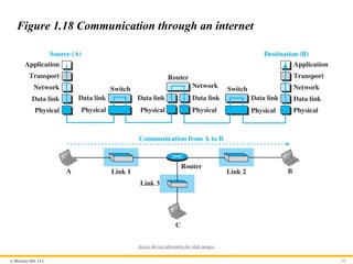
AI-Agents-Concepts-Applications-and-Types.pptx 
PDF
A Newbie’s Journey: Hidden MySQL Pain Points That Vitess Quietly Solves 
PDF
Chip Designer's Code - Linux Terminal Part 7.1 - Text Processing 
PDF
Day 01- Basic Knowledge for LPG system design.pdf 
PPTX
What TPM Looks Like When You’re Short-Staffed and Still Make It Work | Lean T... 
PPTX
SketchUp Pro 2026 – Advanced 3D Modeling Software 
PDF
Chris Elwell Woburn - An Experienced IT Executive 
PDF
Chip Designer's Code - Linux Terminal Part 6 - Text Viewers 
PPTX
Origin of Soil and Grain Size with Introduction and explanation 
PPTX
Using Bangladesh studies in cse why matter ppp.pptx 
PDF
JVM in the Age of AI: 2026 Edition - Deep Dive 
PPTX
Basic Volume Mass Relationship and unit weight as function of volumetric wate... 
PDF
God series - Physics video office crossed 
PPTX
Top 3 winning teams announcement - TechSprint Chapter1DataCommunicationandNetworkingSlides
- 1.
Because learning changeseverything.®
Chapter 01
Introduction
Data Communications and
Networking, With TCP/IP
protocol suite
Sixth Edition
Behrouz A. Forouzan
© 2022 McGraw Hill, LLC. All rights reserved. Authorized only for instructor use in the classroom.
No reproduction or further distribution permitted without the prior written consent of McGraw Hill, LLC.
- 2.
© McGraw Hill,LLC 2
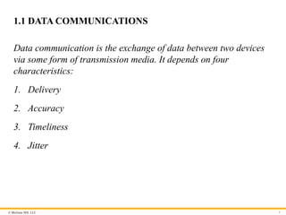
Chapter 3: Outline
1.1 DATA COMMUNICATIONS
1.2 NETWORKS
1.3 NETWORK TYPES
1.4 PROTOCOL LAYERING
1.5 TCP/IP PROTOCOL SUITE
1.6 THE OSI MODEL
- 3.
© McGraw Hill,LLC
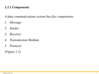
1.1 DATA COMMUNICATIONS
Data communication is the exchange of data between two devices
via some form of transmission media. It depends on four
characteristics:
1. Delivery
2. Accuracy
3. Timeliness
4. Jitter
3
- 4.
© McGraw Hill,LLC
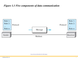
1.1.1 Components
A data communications system has five components:
1. Message
2. Sender
3. Receiver
4. Transmission Medium
5. Protocol
(Figure 1.1)
4
- 5.
© McGraw Hill,LLC 5
Figure 1.1 Five components of data communication
Access the text alternative for slide images.
- 6.
© McGraw Hill,LLC
1.1.2 Message
Information today comes in different forms such as text, numbers,
images, audio, and video.
6
- 7.
© McGraw Hill,LLC
Text
Text is represented as a bit pattern using Unicode.
7
- 8.
- 9.
© McGraw Hill,LLC
Images
Images are represented as bit patterns using either RGB or YCM.
9
- 10.
© McGraw Hill,LLC
Audio
Audio refers to the recording or broadcasting of sound or music,
represented as analog or digital signals.
10
- 11.
© McGraw Hill,LLC
Video
Videos can be a continues images or a combination of images.
11
- 12.
© McGraw Hill,LLC
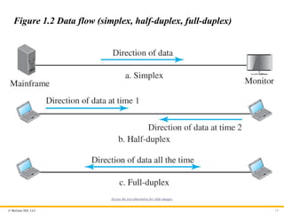
1.1.3 Data Flow
Communication between two devices can be simplex, half-duplex,
and duplex as shown in Figure 1.2.
12
- 13.
© McGraw Hill,LLC 13
Figure 1.2 Data flow (simplex, half-duplex, full-duplex)
Access the text alternative for slide images.
- 14.
© McGraw Hill,LLC
Simplex
In simplex mode the communication is in one direction. Only one of
the two connected devices can send or receive.
14
- 15.
© McGraw Hill,LLC
Half-Duplex
In half-duplex, each station can send or receive, but not at the
same time.
15
- 16.
© McGraw Hill,LLC
Full-Duplex
In full-duplex, both stations can send or receive at the same time.
16
- 17.
© McGraw Hill,LLC
1-2 NETWORKS
A network is the interconnection of a set of devices capable of
communication. In this definition, a device can be a host such as a
large computer, desktop, laptop, workstation, cellular phone, or
security system. A device in this definition can also be a connecting
device such as a router a switch, a modem that changes the form of
data, and so on.
17
- 18.
© McGraw Hill,LLC
1.2.1 Network Criteria
A network must be able to meet a certain number of criteria. The
most important of these are: performance, reliability, and security.
18
- 19.
© McGraw Hill,LLC
Performance
Performance can be measured in many ways, including transit time
and response time. Transit time is the amount of time required for a
message to travel from one device to another. Response time is the
elapsed time between an inquiry and a response.
19
- 20.
© McGraw Hill,LLC
Reliability
In addition to accuracy of delivery, network reliability is measured
by the frequency of failure, the time it takes a link to recover from a
failure, and the network’s robustness in a catastrophe.
20
- 21.
© McGraw Hill,LLC
Security
Network security issues include protecting data from unauthorized
access, protecting data from damage and development, and
implementing policies and procedures for recovery from breaches
and data losses.
21
- 22.
© McGraw Hill,LLC
1.2.2 Physical Structures
Before discussing networks, we need to define some network
structures.
22
- 23.
© McGraw Hill,LLC
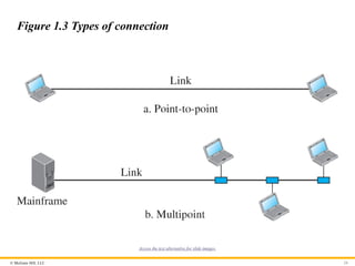
Types of Connection
A network is two or more devices connected through links. A link is
a communications pathway that transfers data from one device to
another. There are two possible types of connections: point-to-point
and multipoint (see Figure 1.3)
23
- 24.
© McGraw Hill,LLC 24
Figure 1.3 Types of connection
Access the text alternative for slide images.
- 25.
© McGraw Hill,LLC
Physical Topology
The term physical topology refers to the way in which a network is
laid out physically. Two or more devices connect to a link; two or
more links form a topology. The topology of a network is the
geometric representation of the relationship of all the links and
linking devices (usually called nodes) to one another. There are
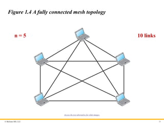
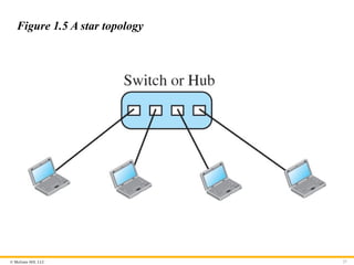
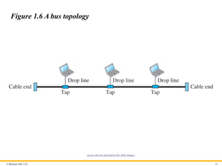
four basic topologies possible: mesh, star, bus, and ring.
25
- 26.
© McGraw Hill,LLC 26
Figure 1.4 A fully connected mesh topology
n = 5 10 links
Access the text alternative for slide images.
- 27.
- 28.
© McGraw Hill,LLC 28
Figure 1.6 A bus topology
Access the text alternative for slide images.
- 29.
© McGraw Hill,LLC 29
Figure 1.7 A ring topology
Access the text alternative for slide images.
- 30.
© McGraw Hill,LLC
1-3 NETWORK TYPES
A network can be of two types: LANs and WANs
30
- 31.
© McGraw Hill,LLC
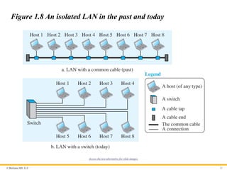
1.3.1 Local Area Network (LAN)
A local area network (LAN) is usually privately owned and
connects some hosts in a single office, building, or campus.
31
- 32.
© McGraw Hill,LLC 32
Figure 1.8 An isolated LAN in the past and today
Access the text alternative for slide images.
- 33.
© McGraw Hill,LLC
1.3.2 Wide Area Network (WAN)
A wide area network (WAN) is also a connection of devices capable
of communication. a WAN has a wider geographical span,
spanning a town, a state, a country, or even the world.
33
- 34.
© McGraw Hill,LLC
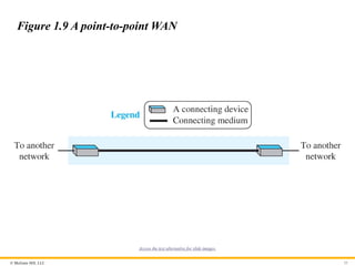
Point-to-Point WAN
A point-to-point WAN is a network that connects two
communicating devices through a transmission media (cable or
air). Figure 1.9 shows an example of a point-to-point WAN.
34
- 35.
© McGraw Hill,LLC 35
Figure 1.9 A point-to-point WAN
Access the text alternative for slide images.
- 36.
© McGraw Hill,LLC
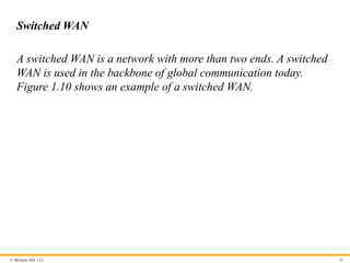
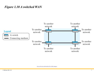
Switched WAN
A switched WAN is a network with more than two ends. A switched
WAN is used in the backbone of global communication today.
Figure 1.10 shows an example of a switched WAN.
36
- 37.
© McGraw Hill,LLC 37
Figure 1.10 A switched WAN
Access the text alternative for slide images.
- 38.
© McGraw Hill,LLC
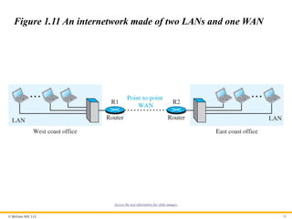
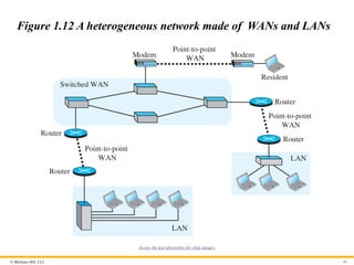
Internetwork
Today, it is very rare to see a LAN or a WAN in isolation; they are
connected to one another. When two or more networks are
connected, they make an internetwork, or internet.
38
- 39.
© McGraw Hill,LLC 39
Figure 1.11 An internetwork made of two LANs and one WAN
Access the text alternative for slide images.
- 40.
© McGraw Hill,LLC 40
Figure 1.12 A heterogeneous network made of WANs and LANs
Access the text alternative for slide images.
- 41.
© McGraw Hill,LLC
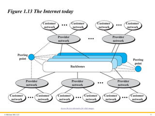
1.3.3 The Internet
An internet (note the lowercase i) is two or more networks that can
communicate with each other. The most notable internet is called
the Internet (uppercase I) and is composed of millions of
interconnected networks. Figure 1.13 shows a conceptual (not
geographical) view of the Internet.
41
- 42.
© McGraw Hill,LLC 42
Figure 1.13 The Internet today
Access the text alternative for slide images.
- 43.
© McGraw Hill,LLC
1.3.4 Accessing the Internet
The Internet today is an internetwork that allows any user to
become part of it. The user, however, needs to be physically
connected to an ISP. The physical connection is normally done
through a point-to-point WAN.
43
- 44.
© McGraw Hill,LLC
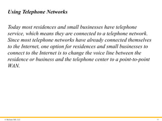
Using Telephone Networks
Today most residences and small businesses have telephone
service, which means they are connected to a telephone network.
Since most telephone networks have already connected themselves
to the Internet, one option for residences and small businesses to
connect to the Internet is to change the voice line between the
residence or business and the telephone center to a point-to-point
WAN.
44
- 45.
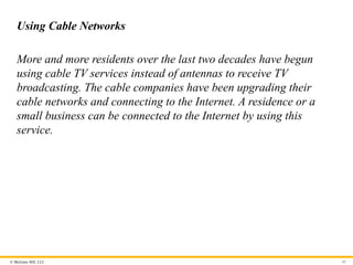
© McGraw Hill,LLC
Using Cable Networks
More and more residents over the last two decades have begun
using cable TV services instead of antennas to receive TV
broadcasting. The cable companies have been upgrading their
cable networks and connecting to the Internet. A residence or a
small business can be connected to the Internet by using this
service.
45
- 46.
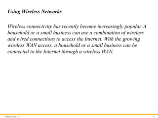
© McGraw Hill,LLC
Using Wireless Networks
Wireless connectivity has recently become increasingly popular. A
household or a small business can use a combination of wireless
and wired connections to access the Internet. With the growing
wireless WAN access, a household or a small business can be
connected to the Internet through a wireless WAN.
46
- 47.
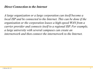
© McGraw Hill,LLC
Direct Connection to the Internet
A large organization or a large corporation can itself become a
local ISP and be connected to the Internet. This can be done if the
organization or the corporation leases a high-speed WAN from a
carrier provider and connects itself to a regional ISP. For example,
a large university with several campuses can create an
internetwork and then connect the internetwork to the Internet.
47
- 48.
© McGraw Hill,LLC
1-4 PROTOCOL LAYERING
We defined the term protocol before. In data communication
and networking, a protocol defines the rules that both the
sender and receiver and all intermediate devices need to
follow to be able to communicate directly.
48
- 49.
© McGraw Hill,LLC
1.4.1 Scenarios
Let us develop two simple scenarios to better understand the need
for protocol layering.
49
- 50.
© McGraw Hill,LLC
First Scenario
A large organization or a large corporation can itself become a
local ISP and be connected to the Internet. This can be done if the
organization or the corporation leases a high-speed WAN from a
carrier provider and connects itself to a regional ISP.
50
- 51.
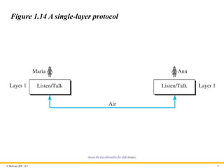
© McGraw Hill,LLC 51
Figure 1.14 A single-layer protocol
Access the text alternative for slide images.
- 52.
© McGraw Hill,LLC
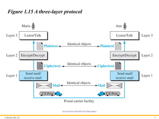
Second Scenario
In the second scenario, we assume that Ann is offered a higher-
level position in her company, but needs to move to another branch
located in a city very far from Maria. They decide to continue their
conversion using regular mail through the post office. However,
they do not want their ideas to be revealed by other people if the
letters are intercepted. They use an encryption/decryption
technique.
52
- 53.
© McGraw Hill,LLC 53
Figure 1.15 A three-layer protocol
Access the text alternative for slide images.
- 54.
© McGraw Hill,LLC
1.4.2 Principles of Protocol Layering
Let us discuss two principles of protocol layering.
54
- 55.
© McGraw Hill,LLC
First Principle
The first principle dictates that we need to make each layer to
perform two opposite task in each direction.
55
- 56.
© McGraw Hill,LLC
Second Principle
The second principle dictates that two objects under each layer
should be identical.
56
- 57.
© McGraw Hill,LLC
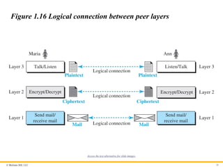
1.4.3 Logical Connections
After following the above two principles, we can think about
logical connection between each layer as shown in Figure 1.16.
57
- 58.
© McGraw Hill,LLC 58
Figure 1.16 Logical connection between peer layers
Access the text alternative for slide images.
- 59.
© McGraw Hill,LLC
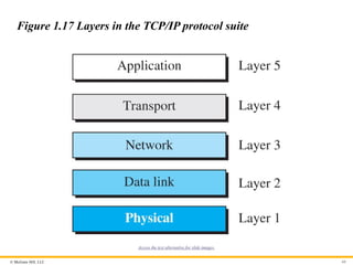
1-5 TCP/IP PROTOCOL SUITE
Now we can introduce the TCP/IP (Transmission Control
Protocol / Internet Protocol). This is the protocol suite used in the
Internet today.
59
- 60.
© McGraw Hill,LLC 60
Figure 1.17 Layers in the TCP/IP protocol suite
Access the text alternative for slide images.
- 61.
© McGraw Hill,LLC
1.5.1 Layered Architecture
To show how the layers in the TCP/IP protocol suite are involved in
communication between two hosts, we assume that we want to use
the suite in a small internet made up of three LANs (links), each
with a link-layer switch. We also assume that the links are
connected by one router, as shown in Figure 1.18.
61
- 62.
© McGraw Hill,LLC 62
Figure 1.18 Communication through an internet
Access the text alternative for slide images.
- 63.
© McGraw Hill,LLC
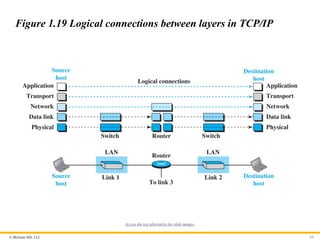
1.5.2 Brief Description of Layers
After the above introduction, we briefly discuss the functions and
duties of layers in the TCP/IP protocol suite. Each layer is
discussed in detail in the next five parts of the book. To better
understand the duties of each layer, we need to think about the
logical connections between layers. Figure 1.19 shows logical
connections in our simple internet.
63
- 64.
© McGraw Hill,LLC 64
Figure 1.19 Logical connections between layers in TCP/IP
Access the text alternative for slide images.
- 65.
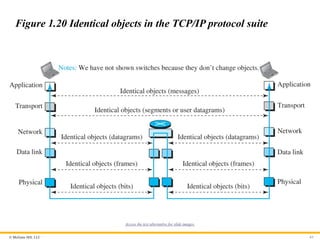
© McGraw Hill,LLC 65
Figure 1.20 Identical objects in the TCP/IP protocol suite
Access the text alternative for slide images.
- 66.
© McGraw Hill,LLC
1.5.3 Description of Each Layer
After understanding the concept of logical communication, we are
ready to briefly discuss the duty of each layer. Our discussion in
this chapter will be very brief, but we come back to the duty of each
layer in next five parts of the book.
66
- 67.
© McGraw Hill,LLC
Physical Layer
We can say that the physical layer is responsible for carrying
individual bits in a frame across the link. The physical layer is the
lowest level in the TCP/IP protocol suite, the communication
between two devices at the physical layer is still a logical
communication because there is another, hidden layer, the
transmission media, under the physical layer. We discuss Physical
Layer in Chapter 2.
67
- 68.
© McGraw Hill,LLC
Data Link Layer
We have seen that an internet is made up of several links (LANs
and WANs) connected by routers. When the next link to travel is
determined by the router, the data-link layer is responsible for
taking the datagram and moving it across the link. We discuss
Data-Link Layer in Chapter 3.
68
- 69.
© McGraw Hill,LLC
Network Layer
The network layer is responsible for creating a connection between
the source computer and the destination computer. The
communication at the network layer is host-to-host. However, since
there can be several routers from the source to the destination, the
routers in the path are responsible for choosing the best route for
each packet. We discuss Network Layer in Chapter 4.
69
- 70.
© McGraw Hill,LLC
Transport Layer
The logical connection at the transport layer is also end-to-end.
The transport layer at the source host gets the message from the
application layer, encapsulates it in a transport-layer packet. In
other words, the transport layer is responsible for giving services
to the application layer: to get a message from an application
program running on the source host and deliver it to the
corresponding application program on the destination host.
transmits user datagrams without first creating a logical
connection. We discuss Transport Layer in Chapter 9.
70
- 71.
© McGraw Hill,LLC
Application Layer
The logical connection between the two application layers is end-
to-end. The two application layers exchange messages between
each other as though there were a bridge between the two layers.
However, we should know that the communication is done through
all the layers. Communication at the application layer is between
two processes (two programs running at this layer). To
communicate, a process sends a request to the other process and
receives a response. Process-to-process communication is the duty
of the application layer. We discuss Application Layer in Chapter
10.
71
- 72.
© McGraw Hill,LLC
1-6 OSI MODEL
Although, when speaking of the Internet, everyone talks about the
TCP/IP protocol suite, this suite is not the only suite of protocols
defined. Established in 1947, the International Organization for
Standardization (ISO) is a multinational body dedicated to
worldwide agreement on international standards. Almost three-
fourths of the countries in the world are represented in the ISO. An
ISO standard that covers all aspects of network communications is
the Open Systems Interconnection (OSI) model. It was first
introduced in the late 1970s.
72
- 73.
© McGraw Hill,LLC 73
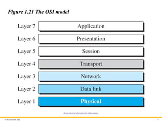
Figure 1.21 The OSI model
Access the text alternative for slide images.
- 74.
© McGraw Hill,LLC
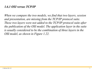
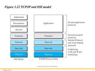
1.6.1 OSI versus TCP/IP
When we compare the two models, we find that two layers, session
and presentation, are missing from the TCP/IP protocol suite.
These two layers were not added to the TCP/IP protocol suite after
the publication of the OSI model. The application layer in the suite
is usually considered to be the combination of three layers in the
OSI model, as shown in Figure 1.22.
74
- 75.
© McGraw Hill,LLC 75
Figure 1.22 TCP/IP and OSI model
Access the text alternative for slide images.
- 76.
© McGraw Hill,LLC
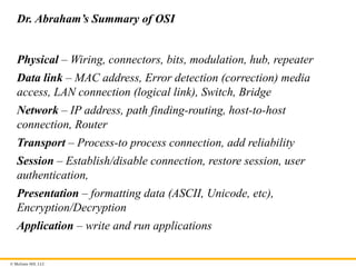
Dr. Abraham’s Summary of OSI
Physical – Wiring, connectors, bits, modulation, hub, repeater
Data link – MAC address, Error detection (correction) media
access, LAN connection (logical link), Switch, Bridge
Network – IP address, path finding-routing, host-to-host
connection, Router
Transport – Process-to process connection, add reliability
Session – Establish/disable connection, restore session, user
authentication,
Presentation – formatting data (ASCII, Unicode, etc),
Encryption/Decryption
Application – write and run applications
- 77.
© McGraw Hill,LLC
1.6.2 Lack of OSI Model’s Success
The OSI model appeared after the TCP/IP protocol suite. Most
experts were at first excited and thought that the TCP/IP protocol
would be fully replaced by the OSI model. This did not happen for
several reasons, but we describe only three, which are agreed upon
by all experts in the field.
77
- 78.
Because learning changeseverything.®
www.mheducation.com
End of Main Content
© 2022 McGraw Hill, LLC. All rights reserved. Authorized only for instructor use in the classroom.
No reproduction or further distribution permitted without the prior written consent of McGraw Hill, LLC.