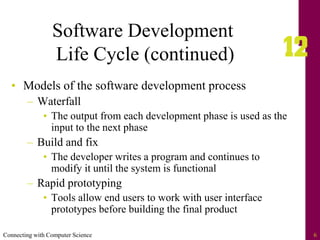
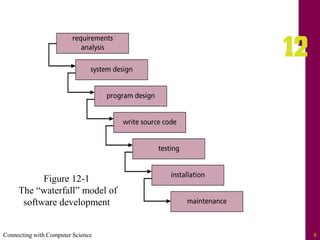
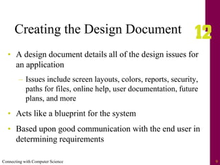
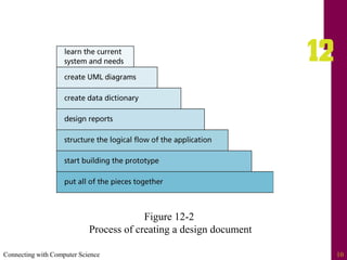
Connecting with Computer Science 2
Objectives
• Learn how software engineering is used to create
applications
• Learn some of the different software engineering
process models
• Understand what a design document is and how it
should be used during software development
• Be introduced to the proper steps in formulating a
design document used in creating an application
Connecting with Computer Science 3
Objectives (continued)
• Learn how Unified Modeling Language (UML)
diagrams can be used as a blueprint in creating an
application
• See some of the pitfalls in developing software, and
learn how to avoid them
• Gain an understanding of how teams are used in
application development
Connecting with Computer Science 4
What is Software Engineering?
• The process of producing software applications
– Source code and data
– UML diagrams and screen prototypes
– Requirements and reports
– Future development issues
• The end user is the driving force behind software
development
– Determines the required functionality of the program
Connecting with Computer Science 5
Software Development
Life Cycle
• Describes the life of the application including the
development, testing, installation, and maintenance of
the program
• Elements of the SDLC
– Project feasibility
– Software specification
– Software design and implementation
– Software validation
– Software evolution
Connecting with Computer Science 6
Software Development
Life Cycle (continued)
• Models of the software development process
– Waterfall
• The output from each development phase is used as the
input to the next phase
– Build and fix
• The developer writes a program and continues to
modify it until the system is functional
– Rapid prototyping
• Tools allow end users to work with user interface
prototypes before building the final product
Connecting with Computer Science 7
Software Development Life
Cycle (continued)
– Incremental
• Development with a series of software releases
– Spiral
• Cycles through the waterfall approach until all
functionality has been completed
– Extreme programming (XP)
• Places emphasis on teamwork and feedback
– Agile Software Development
• Focuses on customer satisfaction through continual
delivery and modifications of software products
Connecting with Computer Science 8
Figure 12-1
The “waterfall” model of
software development
Connecting with Computer Science 9
Creating the Design Document
• A design document details all of the design issues for
an application
– Issues include screen layouts, colors, reports, security,
paths for files, online help, user documentation, future
plans, and more
• Acts like a blueprint for the system
• Based upon good communication with the end user in
determining requirements
Connecting with Computer Science 10
Figure 12-2
Process of creating a design document
Connecting with Computer Science 11
Step 1: Learn the Current System
and Needs
• Case Study: a media inventory for a music store
• Initial task is to establish the end user’s (owner of the
music store) needs and goals
– Ask client to give you samples of desired reports
• Document information client gives you
– Dig for more information if necessary
• Write the project objectives or introduction,
specifications, and requirements
Connecting with Computer Science 12
Figure 12-3
A design document includes the project
introduction, specifications, and requirements
Connecting with Computer Science 13
Step 2: Create UML Diagrams
• Unified Modeling Process (UML) enables developers
to create a visual blueprint of the functionality of the
system
– Provides a way for the client and developer to
communicate
– Visual diagrams are created before any lines of source
code are written
• Tools such as Microsoft Visio can be used to create
UML diagrams
Connecting with Computer Science 14
Figure 12-4
Creating UML diagrams in Microsoft Visio
Connecting with Computer Science 15
Some Types of UML Diagrams
• Class
– Shows how different object classes relate to each other
• Object
– Gives details of an object created from a class
• Use case
– Describes a system’s behavior from a user’s standpoint
Connecting with Computer Science 16
Types of UML Diagrams
(continued)
• State
– Shows an object’s particular state at any given time
• Sequence
– Shows how one class communicates with another class
by sending messages back and forth
• Activity
– Shows activities that occur within a use case or within
an object’s behavior
Connecting with Computer Science 17
Types of UML Diagrams
(continued)
• Collaboration
– Shows how system elements work together to
accomplish the system’s objectives
• Component
– Shows how system components relate to each other
• Deployment
– Shows physical architecture of a computer-based
system
Connecting with Computer Science 18
Figure 12-5
Use case diagram for music inventory application
Connecting with Computer Science 19
Figure 12-6
Class diagram for music inventory application
Connecting with Computer Science 20
Figure 12-7
Sequence diagram for music inventory application
Connecting with Computer Science 21
Step 3: Create the Data
Dictionary
• If a database is needed, create a data dictionary
– Document describing the type of data being utilized
within the program
• Shows table definitions, indexes, and other data
relationships
• Use information from end users to summarize the
current system and organize a brief plan for the new
application
• Review end-user reports to find tables and elements
Connecting with Computer Science 22
Figure 12-8
Creating a data dictionary
Connecting with Computer Science 23
Step 4: Design Reports
• Meet with users and let them help you design the
reports
– Review data dictionary
– Use an Integrated Development Environment (IDE)
• Use the reporting tools in the IDE to interactively create
report prototypes with the users
Connecting with Computer Science 24
Figure 12-9
Example of report created with report generator
Connecting with Computer Science 25
Step 5: Structuring the Logical
Flow of the Application
• Create logical flow of application before you begin
writing source code with
– Flowcharts
• Combination of symbols and text that provide a visual
description of a process
– Pseudocode
• Detail the main functionality of the system and the
relationship of the different tasks to be completed
Connecting with Computer Science 26
Figure 12-10
Flowchart
Connecting with Computer Science 27
Figure 12-11
Flowchart symbols
Connecting with Computer Science 28
Step 6: Start Building
the Prototype
• Prototype: typical example that gives end users a
good idea of what they will see when their application
is completed
– Ask end users as many questions as possible to
understand main functionality of the program
– Do not write source code until project specifications
are approved!
– Let the user help you design the screens
• Opening screen should reflect the purpose of the client
and main function of the program
Connecting with Computer Science 29
Step 7: Putting All of the
Pieces Together
• Take all of the gathered information and create the
design document
– Be realistic in defining project completion dates, time
lines, and price estimates
– Make user sign the design document, thus agreeing to
the deadline defined by the scope of the project
– Create addendums when modifications to the
document are needed
Connecting with Computer Science 30
Step 7: Putting All of the Pieces
Together (continued)
• Include the following items in the design document
– Header page, objective, definition of terms
– Project feasibility study, specifications, requirements,
and cost analysis
– Data dictionary and all visual diagrams
– Copies of screens, and reports
– Testing and user feedback plans
– Notes from meetings
Connecting with Computer Science 31
Avoiding the Pitfalls
• User-phobia
– Fears that including end user in design process will
result in failure
– Solution: Keep communication open
• Too much work
– The “heap on the work” syndrome
– Solution: Be assertive and honest with the manager
• Scope creep
– Making continual changes and extensions
– Solution: Use a phased approach to development
Connecting with Computer Science 32
The Project
Development Team
• Project manager
– Responsible for choosing the right players for the right
positions
– Determines risk involved with project, cost, and the
scheduling of tasks
– Pulls together the design document
• Creator of the database (database administrator)
– Creates and maintains database structure
Connecting with Computer Science 33
Figure 12-12
A project management tool helps a manager
keep track of the status of the project
Connecting with Computer Science 34
The Project Development Team
(continued)
• Developers (programmers)
– Responsible for writing source code to meet
functional requirements of the end user
• Client (end user)
– Driving force behind project
• Tester
– Responsible for making sure the program functions
correctly and meets all functional requirements in the
design document
• Test all possible situations and keep a log of errors
Connecting with Computer Science 35
The Project Development Team
(continued)
• Customer relations representative
– Interface between the testers, developers, and end
users during product creation and early release cycles
• Generator of the application CD
– Interface with developers to ensure that all of the
necessary files are included on the disks
• Installer of the application disks
– Installs disk on the end user’s machine and gives the
user a guided tour of the application
Connecting with Computer Science 36
One Last Thought
• Good design results in good programs
– Skipping steps will result in poor performance, unmet
client needs, or a project that runs over budget and
over schedule
• The project manager’s primary responsibilities are to
build a team that can work well together, and to keep
the project on schedule and within budget
• Include a thorough testing cycle
Connecting with Computer Science 37
Summary
• Software engineering involves many different steps
that can be followed in order to create an application
that meets an end user’s needs
• The process of building the application is
accomplished by implementing a software
development life cycle (SDLC) process
• Each SDLC provides a different way of detailing the
steps used in creating a software product
Connecting with Computer Science 38
Summary (continued)
• A design document acts as a blueprint for software
development
• Several steps when creating a design document
– Researching the needs of the end user, communication,
logical design of screens, reports, and data structures,
etc.
• UML enables developers and end users to visually
design the functionality of the system
Connecting with Computer Science 39
Summary (continued)
• Several types of UML diagrams, each for a
particular purpose or a part of a system
• Using the reports and the data dictionary can help a
developer assess any design “holes”
• Software development is often a team effort
– Team members include a project manager, database
administrator, developer/programmer, client/end
users, a tester, and sometimes customer relations
Connecting with Computer Science 40
Summary (continued)
• Once the application has been developed, installation
disks need to be generated
• After the system is installed on the client’s system,
spend some time training initial end users, who can
in turn train other end users

chapter12 - Software engineering.pdf

  • 2.
    Connecting with ComputerScience 2 Objectives • Learn how software engineering is used to create applications • Learn some of the different software engineering process models • Understand what a design document is and how it should be used during software development • Be introduced to the proper steps in formulating a design document used in creating an application
  • 3.
    Connecting with ComputerScience 3 Objectives (continued) • Learn how Unified Modeling Language (UML) diagrams can be used as a blueprint in creating an application • See some of the pitfalls in developing software, and learn how to avoid them • Gain an understanding of how teams are used in application development
  • 4.
    Connecting with ComputerScience 4 What is Software Engineering? • The process of producing software applications – Source code and data – UML diagrams and screen prototypes – Requirements and reports – Future development issues • The end user is the driving force behind software development – Determines the required functionality of the program
  • 5.
    Connecting with ComputerScience 5 Software Development Life Cycle • Describes the life of the application including the development, testing, installation, and maintenance of the program • Elements of the SDLC – Project feasibility – Software specification – Software design and implementation – Software validation – Software evolution
  • 6.
    Connecting with ComputerScience 6 Software Development Life Cycle (continued) • Models of the software development process – Waterfall • The output from each development phase is used as the input to the next phase – Build and fix • The developer writes a program and continues to modify it until the system is functional – Rapid prototyping • Tools allow end users to work with user interface prototypes before building the final product
  • 7.
    Connecting with ComputerScience 7 Software Development Life Cycle (continued) – Incremental • Development with a series of software releases – Spiral • Cycles through the waterfall approach until all functionality has been completed – Extreme programming (XP) • Places emphasis on teamwork and feedback – Agile Software Development • Focuses on customer satisfaction through continual delivery and modifications of software products
  • 8.
    Connecting with ComputerScience 8 Figure 12-1 The “waterfall” model of software development
  • 9.
    Connecting with ComputerScience 9 Creating the Design Document • A design document details all of the design issues for an application – Issues include screen layouts, colors, reports, security, paths for files, online help, user documentation, future plans, and more • Acts like a blueprint for the system • Based upon good communication with the end user in determining requirements
  • 10.
    Connecting with ComputerScience 10 Figure 12-2 Process of creating a design document
  • 11.
    Connecting with ComputerScience 11 Step 1: Learn the Current System and Needs • Case Study: a media inventory for a music store • Initial task is to establish the end user’s (owner of the music store) needs and goals – Ask client to give you samples of desired reports • Document information client gives you – Dig for more information if necessary • Write the project objectives or introduction, specifications, and requirements
  • 12.
    Connecting with ComputerScience 12 Figure 12-3 A design document includes the project introduction, specifications, and requirements
  • 13.
    Connecting with ComputerScience 13 Step 2: Create UML Diagrams • Unified Modeling Process (UML) enables developers to create a visual blueprint of the functionality of the system – Provides a way for the client and developer to communicate – Visual diagrams are created before any lines of source code are written • Tools such as Microsoft Visio can be used to create UML diagrams
  • 14.
    Connecting with ComputerScience 14 Figure 12-4 Creating UML diagrams in Microsoft Visio
  • 15.
    Connecting with ComputerScience 15 Some Types of UML Diagrams • Class – Shows how different object classes relate to each other • Object – Gives details of an object created from a class • Use case – Describes a system’s behavior from a user’s standpoint
  • 16.
    Connecting with ComputerScience 16 Types of UML Diagrams (continued) • State – Shows an object’s particular state at any given time • Sequence – Shows how one class communicates with another class by sending messages back and forth • Activity – Shows activities that occur within a use case or within an object’s behavior
  • 17.
    Connecting with ComputerScience 17 Types of UML Diagrams (continued) • Collaboration – Shows how system elements work together to accomplish the system’s objectives • Component – Shows how system components relate to each other • Deployment – Shows physical architecture of a computer-based system
  • 18.
    Connecting with ComputerScience 18 Figure 12-5 Use case diagram for music inventory application
  • 19.
    Connecting with ComputerScience 19 Figure 12-6 Class diagram for music inventory application
  • 20.
    Connecting with ComputerScience 20 Figure 12-7 Sequence diagram for music inventory application
  • 21.
    Connecting with ComputerScience 21 Step 3: Create the Data Dictionary • If a database is needed, create a data dictionary – Document describing the type of data being utilized within the program • Shows table definitions, indexes, and other data relationships • Use information from end users to summarize the current system and organize a brief plan for the new application • Review end-user reports to find tables and elements
  • 22.
    Connecting with ComputerScience 22 Figure 12-8 Creating a data dictionary
  • 23.
    Connecting with ComputerScience 23 Step 4: Design Reports • Meet with users and let them help you design the reports – Review data dictionary – Use an Integrated Development Environment (IDE) • Use the reporting tools in the IDE to interactively create report prototypes with the users
  • 24.
    Connecting with ComputerScience 24 Figure 12-9 Example of report created with report generator
  • 25.
    Connecting with ComputerScience 25 Step 5: Structuring the Logical Flow of the Application • Create logical flow of application before you begin writing source code with – Flowcharts • Combination of symbols and text that provide a visual description of a process – Pseudocode • Detail the main functionality of the system and the relationship of the different tasks to be completed
  • 26.
    Connecting with ComputerScience 26 Figure 12-10 Flowchart
  • 27.
    Connecting with ComputerScience 27 Figure 12-11 Flowchart symbols
  • 28.
    Connecting with ComputerScience 28 Step 6: Start Building the Prototype • Prototype: typical example that gives end users a good idea of what they will see when their application is completed – Ask end users as many questions as possible to understand main functionality of the program – Do not write source code until project specifications are approved! – Let the user help you design the screens • Opening screen should reflect the purpose of the client and main function of the program
  • 29.
    Connecting with ComputerScience 29 Step 7: Putting All of the Pieces Together • Take all of the gathered information and create the design document – Be realistic in defining project completion dates, time lines, and price estimates – Make user sign the design document, thus agreeing to the deadline defined by the scope of the project – Create addendums when modifications to the document are needed
  • 30.
    Connecting with ComputerScience 30 Step 7: Putting All of the Pieces Together (continued) • Include the following items in the design document – Header page, objective, definition of terms – Project feasibility study, specifications, requirements, and cost analysis – Data dictionary and all visual diagrams – Copies of screens, and reports – Testing and user feedback plans – Notes from meetings
  • 31.
    Connecting with ComputerScience 31 Avoiding the Pitfalls • User-phobia – Fears that including end user in design process will result in failure – Solution: Keep communication open • Too much work – The “heap on the work” syndrome – Solution: Be assertive and honest with the manager • Scope creep – Making continual changes and extensions – Solution: Use a phased approach to development
  • 32.
    Connecting with ComputerScience 32 The Project Development Team • Project manager – Responsible for choosing the right players for the right positions – Determines risk involved with project, cost, and the scheduling of tasks – Pulls together the design document • Creator of the database (database administrator) – Creates and maintains database structure
  • 33.
    Connecting with ComputerScience 33 Figure 12-12 A project management tool helps a manager keep track of the status of the project
  • 34.
    Connecting with ComputerScience 34 The Project Development Team (continued) • Developers (programmers) – Responsible for writing source code to meet functional requirements of the end user • Client (end user) – Driving force behind project • Tester – Responsible for making sure the program functions correctly and meets all functional requirements in the design document • Test all possible situations and keep a log of errors
  • 35.
    Connecting with ComputerScience 35 The Project Development Team (continued) • Customer relations representative – Interface between the testers, developers, and end users during product creation and early release cycles • Generator of the application CD – Interface with developers to ensure that all of the necessary files are included on the disks • Installer of the application disks – Installs disk on the end user’s machine and gives the user a guided tour of the application
  • 36.
    Connecting with ComputerScience 36 One Last Thought • Good design results in good programs – Skipping steps will result in poor performance, unmet client needs, or a project that runs over budget and over schedule • The project manager’s primary responsibilities are to build a team that can work well together, and to keep the project on schedule and within budget • Include a thorough testing cycle
  • 37.
    Connecting with ComputerScience 37 Summary • Software engineering involves many different steps that can be followed in order to create an application that meets an end user’s needs • The process of building the application is accomplished by implementing a software development life cycle (SDLC) process • Each SDLC provides a different way of detailing the steps used in creating a software product
  • 38.
    Connecting with ComputerScience 38 Summary (continued) • A design document acts as a blueprint for software development • Several steps when creating a design document – Researching the needs of the end user, communication, logical design of screens, reports, and data structures, etc. • UML enables developers and end users to visually design the functionality of the system
  • 39.
    Connecting with ComputerScience 39 Summary (continued) • Several types of UML diagrams, each for a particular purpose or a part of a system • Using the reports and the data dictionary can help a developer assess any design “holes” • Software development is often a team effort – Team members include a project manager, database administrator, developer/programmer, client/end users, a tester, and sometimes customer relations
  • 40.
    Connecting with ComputerScience 40 Summary (continued) • Once the application has been developed, installation disks need to be generated • After the system is installed on the client’s system, spend some time training initial end users, who can in turn train other end users