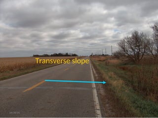
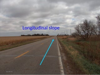
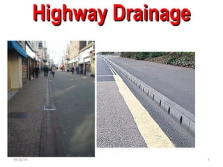
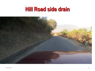
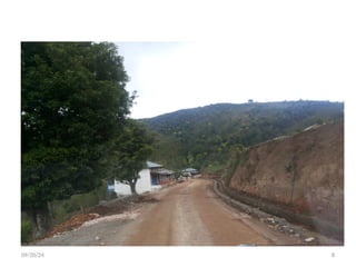
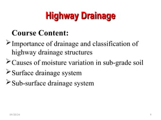
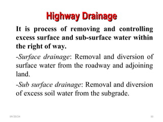
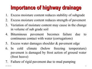
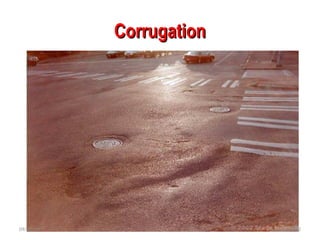
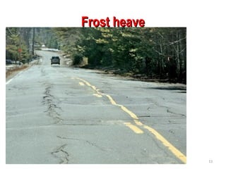
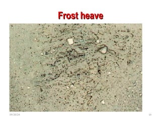
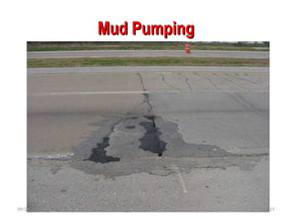
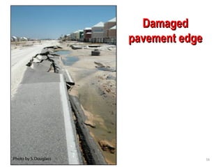
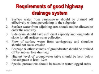
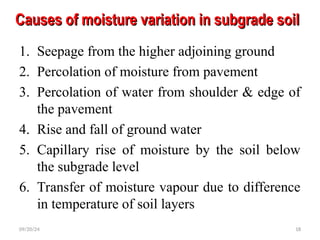
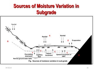
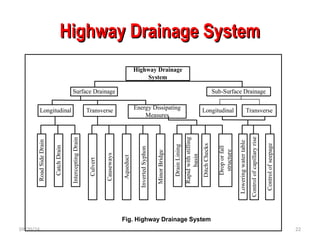
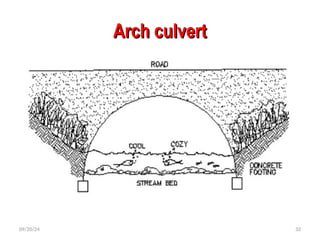
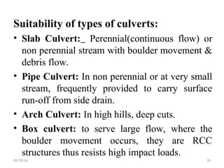
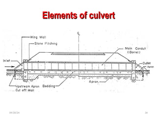
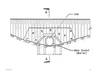
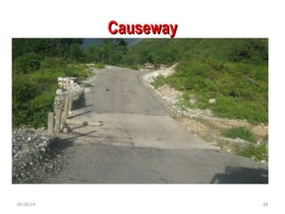
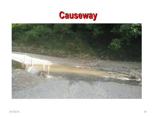
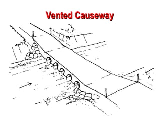
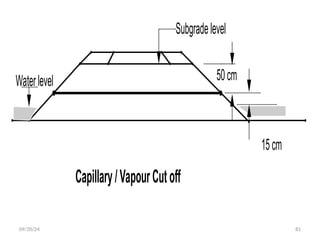
Highway Drainage
Highway Drainage
09/20/24 1
2
Longitudinal channel
09/20/24
3
Transverse slope
09/20/24
4
Longitudinal slope
09/20/24
Highway Drainage
Highway Drainage
5
09/20/24
Hill Road side drain
09/20/24 6
09/20/24 7
09/20/24 8
Highway Drainage
Highway Drainage
Course Content:
Importance of drainage and classification of
highway drainage structures
Causes of moisture variation in sub-grade soil
Surface drainage system
Sub-surface drainage system
09/20/24 9
Highway Drainage
Highway Drainage
It is process of removing and controlling
excess surface and sub-surface water within
the right of way.
-Surface drainage: Removal and diversion of
surface water from the roadway and adjoining
land.
-Sub surface drainage: Removal and diversion
of excess soil water from the subgrade.
09/20/24 10
Importance of highway drainage
1. Excess moisture content reduces stability of subgrade
2. Excess moisture content reduces strength of pavement
3. Variation of moisture content may cause in the change
in volume of sub grade soil
4. Bituminous pavement becomes failure due to
continuous contact with water (corrugations)
5. Excess water damages shoulder & pavement edge
6. In cold climate (below freezing temperature)
pavement is damaged by frost action of ground water
(frost heave)
7. Failure of rigid pavement due to mud pumping
09/20/24 11
Corrugation
Corrugation
12
09/20/24
Frost heave
Frost heave
13
09/20/24
Frost heave
Frost heave
14
09/20/24
Mud Pumping
Mud Pumping
15
09/20/24
Damaged
Damaged
pavement edge
pavement edge
09/20/24 16
Requirements of good highway
drainage system
drainage system
1. Surface water from carriageway should be drained off
effectively without percolating to the subgrade
2. Surface water from adjoining area should not be allowed to
enter the roadway
3. Side drain should have sufficient capacity and longitudinal
slope for all surface water collection
4. Flow of surface water from carriageway and shoulder
should not cause erosion
5. Seepage & other sources of groundwater should be drained
off by sub-surface drainage
6. Highest level of groundwater table should be kept below
the subgrade at least 1.2m
7. Special precautions should be taken in water logged areas
09/20/24 17
Causes of moisture variation in subgrade soil
1. Seepage from the higher adjoining ground
2. Percolation of moisture from pavement
3. Percolation of water from shoulder & edge of
the pavement
4. Rise and fall of ground water
5. Capillary rise of moisture by the soil below
the subgrade level
6. Transfer of moisture vapour due to difference
in temperature of soil layers
09/20/24 18
Water balance in soil subgrade
W = (A+B+C)-(D+E+F)
W = water content in subgrade soil at any time of the year.
A = water infiltrated into subgrade soil during rainfall
B = water seeping towards subgrade from adjoining higher ground.
C = water coming to subgrade due to
– Capillary rise
– Upward movement of water table
– Transfer of vapour from lower soil layers.
D = Loss of water from subgrade due to flow away towards lower
adjacent ground.
E = Loss of water due to evaporation, transpiration
F = Loss of water due to percolation down ward
09/20/24 19
Sources of Moisture Variation in
Subgrade
Subgrade
09/20/24 20
Rainfall
Rainfall
Rainfall
Normal ground water table
Capillary
Rise
Vapour
movement
Upward movement of
GWT
Percolating
downward
Fig. Sources of moisture variation in sub-grade
A
B
C C
C
F
Away towards lower adj.
ground
D
Evaporation
E
Components of Highway drainage System:
–Surface Drainage system
–Sub-surface Drainage system
09/20/24 21
Highway Drainage System
09/20/24 22
Highway Drainage
System
Road
Side
Drain
Sub-Surface Drainage
Surface Drainage
Longitudinal Transverse Energy Dissipating
Measures
Longitudinal Transverse
Catch
Drain
Intercepting
Drain
Culvert
Causeways
Aqueduct
Inverted
Syphon
Minor
Bridge
Control
of
capillary
rise
Control
of
seepage
Drop
or
fall
structure
Ditch
Checks
Rapid
with
stilling
basin
Drain
Lining
Lowering
water
table
Fig. Highway Drainage System
Surface Drainage
Surface Drainage
Highway drainage system consists of:
• Removal of water laterally during rainfall
towards road side by providing camber, cross
falls on shoulder
• Trapped runoff is allowed to flow along
roadway by providing side drain.
• Cross drainage are provided for the final
removal of water from side drains by means of
culverts, bridges, causeways etc.
09/20/24 23
Drains
Drains
• Drains are generally provided along the roadside
in order to intercept surface water running off the
carriageway, shoulders and side slopes bordering
the roadway.
• If the cut slopes and hill side slopes are long
enough and accumulates more water than the
capacity of usual sized side drain and if the run
off may erode the slope then the run off is
intercepted on its way to roadway by providing
drains at these slope itself.
• These drains are known as intercepting drains
and are common drainage components in hill
roads.
09/20/24 24
Typical side Drains
Typical side Drains
09/20/24 25
0.6 m
>
0.3
m
>
0.3
m
0.4
-
0.6
m
0.4 - 0.5 m
A) Trapezoidal
B) Triangular
C) Rectangular
Fig. Typical Side drains
Cross Drainage Structures
Importance:
• Adequate functioning of a road depends to a large extent on
the effectiveness of cross drainages.
• A road has to be aligned to cut across natural drainage
channels and major rivers.
• At the same time the road cuts across man made channels
(irrigation).
• The function of the cross drainage structures is to ensure
that the run-off water is discharged across the road from one
side to the other, as quickly as possible, without causing
undue pounding, overtopping of the road embankment or
erosion of the portion of the road.
• Quick drainage, prevents water from penetrating the soil in
the embankment. A dry subgrade has greater bearing
strength than wet subgrade.
09/20/24 26
Types of cross drainage structures
– Culverts: upto 6 m length
– Minor bridge: more than 6 m and upto 20 m
length
– Medium bridge: Above 20 m length, span length
less than 20 m.
– Major bridge: bridge with span length greater
than 20 m.
– Causeway: which allow the water to flow over the
road way.
09/20/24 27
Types of Culvert:
–Pipe culvert
–Slab Culvert
–Box Culvert
–Arch Culvert
09/20/24 28
Pipe culvert
Pipe culvert
09/20/24 29
Slab culvert
Slab culvert
09/20/24 30
Box culvert
Box culvert
09/20/24 31
Arch culvert
Arch culvert
09/20/24 32
Suitability of types of culverts:
• Slab Culvert: Perennial(continuous flow) or
non perennial stream with boulder movement &
debris flow.
• Pipe Culvert: In non perennial or at very small
stream, frequently provided to carry surface
run-off from side drain.
• Arch Culvert: In high hills, deep cuts.
• Box culvert: to serve large flow, where the
boulder movement occurs, they are RCC
structures thus resists high impact loads.
09/20/24 33
Elements of culvert
Elements of culvert
09/20/24 34
09/20/24 35
• Depending upon the type of soil foundation
there may be either sand bedding or PCC or
RCC.
• Inlet or outlet structure consists of apron.
• Cutoff wall on its base and wing wall on its
side to protect earth slope and to streamline the
flow. Slope embankment should be protected
with stone pitching, gabion work etc.
• Additional elements like hand rail, parapet
wall may be provided.
09/20/24 36
Culvert location, layout & selection
Proper location is necessary for the efficient & economic
operation of the culvert.
• Near to the natural water course in respect of both plan and
profile.
• Perpendicular or skew culverts are compared on the basis of
cost.
• Slope of the culvert should be normally as the natural bed
slope of water course. (min 0.5 % is allowable).
• Selection of the type of the culverts:
– Availability of construction material & technology
– Nature of the water course
– Economic comparison
– Importance of road
09/20/24 37
EROSION CONTROL AND
EROSION CONTROL AND
ENERGY DISSIPATION MEASURES:
• Velocity of water will be higher than non scouring
velocity at:
– After the outlet of the culvert or cross drainage
– High bed slope of side drain & intercepting drains
• High velocity of water may cause:
– Erosion of hill slope bed
– Removal of vegetation layer.
• Control of the erosion is directly concerned with
the dissipation of energy which ultimately means
the reduction of velocity
09/20/24 38
Erosion Control & Energy Dissipating
Measures
Measures
1. Drain lining
–For the particular type of soil; mean
velocity may exceed than permissible &
it should be protected against scouring.
–Slope of the drain is lined with turf and
bottom is covered by cobbles & gravels
of desired sizes.
09/20/24 39
Bed slope Type of bed soil Type of lining
Up to 1% Sandy Soil No lining
Up to 2% Clay No lining
(1-2)% Sandy Soil Turfing
(2-4)% Clayey Soil Turfing
Up to 5% All types Dry stone paving
More than 5% All types
Ditch checks and stone
masonry continuous lining
09/20/24 40
2. Ditch Checks (Drops):
• Continuous lining with stone
masonry in cement mortar is
expensive and whenever possible bed
slopes are made gentle by providing
falls at certain interval, such type of
structure is known as ditch checks.
09/20/24 41
09/20/24 42
1.5m
l
i2
0.8m
h
Shouldbeprotectedfrom
Scouring
Ditch Checks
3. Road Rapids:
• Road channels having bed slope more
than critical slope are referred as rapids.
• Rapids are provided on short length.
• It is provided at the end section of catch
or intercepting drains.
09/20/24 43
09/20/24 44
09/20/24 45
09/20/24 46
Stilling Basin
Outlet Apron
Main conduit Rapid
Inlet Apron
A
B
Section at A-B
09/20/24 47
d0
l0
ho
hc
H
hn
h2
4. Fall or Drop Structure:
• They are provided both upstream &
downstream of cross drainage.
• Different types of drop structures:
a) Drop without stilling basin and friction wall
b)Drop with stilling basin
c) Drop with frictional wall
d) Drop with frictional wall and stilling basin
09/20/24 48
09/20/24 49
09/20/24 50
09/20/24 51
09/20/24 52
09/20/24 53
MISCELLANEOUS EROSION CONTROL
MEASURES
MEASURES
Main reasons on soil erosion:
– Formation of new fills & cut slopes
– Excavation of drainage way
– Diversion of waterways along new channels
– Embankment construction
– Removal of top soil
– Increase in human activities on construction site
– Deforestation
09/20/24 54
MISCELLANEOUS EROSION CONTROL MEASURES
a) Vegetation:
– For slopes 1:1.5 and flatter, turf & other ground
cover could be rapidly established.
– Ground covered with low growing herbaceous or
woody plants are arranged.
– Trees & shrubs on steep hill slopes.
– Trees, shrubs and grass on road surrounding
usually satisfy multiple function.
– Vegetation plays aesthetical role also.
09/20/24 55
b) Slope pitching, lining & Protection walls:
– Dry stone pitching
– Armour rock protection
– Gabion crates filled pitching
– Stone masonry with cement mortar
– Concrete block lining
– Retaining wall
09/20/24 56
Dry stone pitching
Dry stone pitching
09/20/24 57
Armour rock protection
09/20/24 58
(High weight Rock)
Gabion creates filled pitching
09/20/24 59
Stone masonry in C.M.
09/20/24 60
Retaining wall
Retaining wall
09/20/24 61
Retaining wall
Concrete block
Concrete block
09/20/24 62
K
Concrete block lining
09/20/24 63
c) Bank protection spur & check dams:
– Spur: perpendicular structure to the direction of
flow to dissipate the water energy & protect the
erosion.
– Check Dams: structures constructed across the
stream having high bed slope in a particular
section to retain boulder or bed material.
09/20/24 64
Spur
Spur
09/20/24 65
Check Dam
Check Dam
09/20/24 66
Other Miscellaneous Cross drainage
structures
structures
1. Causeways:
• A cross drainage structure with or without openings below road
surface provided across a shallow drainage course at or about the
bed level which allows floods/ runoff to pass over it is referred as
Causeway.
– A causeway with vents below to pass regular flow under
the road and flash flood across the road surface is often
known as high level causeway or submersible bridge.
– A causeway constructed at bed level which allows flood to
pass over the road surface at any time is referred as flush
causeway. It is sometimes called as Ford.
09/20/24 67
Causeway
Causeway
09/20/24 68
Causeway
Causeway
09/20/24 69
Vented Causeway
Vented Causeway
09/20/24 70
09/20/24 71
Sub-surface Drainage
• Surface drainage system is the preventive
measure to control excessive moisture in
sub-grade soil and various pavement layers.
Unfortunately, whatever effective measures
for the surface drainage may be considered,
water finds its own way to get into the sub-
grade and further below. The provision of
drainage under the ground surface is
referred as sub-surface.
09/20/24 72
Subsurface drainage system
• Drainage of infiltrated water
• Control of seepage flow
• Lowering water level
• Measures for capillary vapour transfer cut off
09/20/24 73
Drainage of infiltrated water
09/20/24 74
Clay Seal
Sand Blanket 15-25 cm
Filter material
Perforated pipe 15-20 cm
Lean Concrete or sand bedding
1. Drainage of infiltrated water
Control of seepage flow
09/20/24 75
Impermeable strata
Road Side drain
2. Interception of seepage flow by surface drainage
Control of seepage flow
09/20/24 76
Impervious Strata
Seepage flow
B) impervious strata deep below
Lowering water level
09/20/24 77
Impervious Strata
Original seepage line
Lowered Seepage line
1.25
m
Interception of Seepage by French Drain
Measures for capillary vapor transfer
cut off
cut off
• In water logged areas capillary action is more
severe, if roads are constructed from fine
grained soil. In such cases, capillary cutoff are
provided, to make the subgrade soil free from
excessive moisture.
• Moisture movement in the form of vapor is
resulted where substantial fluctuation in daily
temperature takes place
09/20/24 78
Some suitable Measures:
• Sand blanket for capillary cut off
• Tarfelt for both capillary cut off & vapor
movement
• Polythene envelops for capillary cut off and
vapour movement
• Use of impermeable membrane (bitumen)
• Bitumen stabilized soil for impermeable
membrane
09/20/24 79
09/20/24 80
Tar Felt
09/20/24 81
50cm
15cm
Subgradelevel
Waterlevel
Capillary/VapourCutoff
09/20/24 82
THANK YOU

Chapter Four-Highway Drainage Final.pptndk

  • 1.
  • 2.
  • 3.
  • 4.
  • 5.
  • 6.
    Hill Road sidedrain Hill Road side drain 09/20/24 6
  • 7.
  • 8.
  • 9.
    Highway Drainage Highway Drainage CourseContent: Importance of drainage and classification of highway drainage structures Causes of moisture variation in sub-grade soil Surface drainage system Sub-surface drainage system 09/20/24 9
  • 10.
    Highway Drainage Highway Drainage Itis process of removing and controlling excess surface and sub-surface water within the right of way. -Surface drainage: Removal and diversion of surface water from the roadway and adjoining land. -Sub surface drainage: Removal and diversion of excess soil water from the subgrade. 09/20/24 10
  • 11.
    Importance of highwaydrainage Importance of highway drainage 1. Excess moisture content reduces stability of subgrade 2. Excess moisture content reduces strength of pavement 3. Variation of moisture content may cause in the change in volume of sub grade soil 4. Bituminous pavement becomes failure due to continuous contact with water (corrugations) 5. Excess water damages shoulder & pavement edge 6. In cold climate (below freezing temperature) pavement is damaged by frost action of ground water (frost heave) 7. Failure of rigid pavement due to mud pumping 09/20/24 11
  • 12.
  • 13.
  • 14.
  • 15.
  • 16.
  • 17.
    Requirements of goodhighway Requirements of good highway drainage system drainage system 1. Surface water from carriageway should be drained off effectively without percolating to the subgrade 2. Surface water from adjoining area should not be allowed to enter the roadway 3. Side drain should have sufficient capacity and longitudinal slope for all surface water collection 4. Flow of surface water from carriageway and shoulder should not cause erosion 5. Seepage & other sources of groundwater should be drained off by sub-surface drainage 6. Highest level of groundwater table should be kept below the subgrade at least 1.2m 7. Special precautions should be taken in water logged areas 09/20/24 17
  • 18.
    Causes of moisturevariation in subgrade soil Causes of moisture variation in subgrade soil 1. Seepage from the higher adjoining ground 2. Percolation of moisture from pavement 3. Percolation of water from shoulder & edge of the pavement 4. Rise and fall of ground water 5. Capillary rise of moisture by the soil below the subgrade level 6. Transfer of moisture vapour due to difference in temperature of soil layers 09/20/24 18
  • 19.
    Water balance insoil subgrade Water balance in soil subgrade W = (A+B+C)-(D+E+F) W = water content in subgrade soil at any time of the year. A = water infiltrated into subgrade soil during rainfall B = water seeping towards subgrade from adjoining higher ground. C = water coming to subgrade due to – Capillary rise – Upward movement of water table – Transfer of vapour from lower soil layers. D = Loss of water from subgrade due to flow away towards lower adjacent ground. E = Loss of water due to evaporation, transpiration F = Loss of water due to percolation down ward 09/20/24 19
  • 20.
    Sources of MoistureVariation in Sources of Moisture Variation in Subgrade Subgrade 09/20/24 20 Rainfall Rainfall Rainfall Normal ground water table Capillary Rise Vapour movement Upward movement of GWT Percolating downward Fig. Sources of moisture variation in sub-grade A B C C C F Away towards lower adj. ground D Evaporation E
  • 21.
    Components of Highwaydrainage System: –Surface Drainage system –Sub-surface Drainage system 09/20/24 21
  • 22.
    Highway Drainage System HighwayDrainage System 09/20/24 22 Highway Drainage System Road Side Drain Sub-Surface Drainage Surface Drainage Longitudinal Transverse Energy Dissipating Measures Longitudinal Transverse Catch Drain Intercepting Drain Culvert Causeways Aqueduct Inverted Syphon Minor Bridge Control of capillary rise Control of seepage Drop or fall structure Ditch Checks Rapid with stilling basin Drain Lining Lowering water table Fig. Highway Drainage System
  • 23.
    Surface Drainage Surface Drainage Highwaydrainage system consists of: • Removal of water laterally during rainfall towards road side by providing camber, cross falls on shoulder • Trapped runoff is allowed to flow along roadway by providing side drain. • Cross drainage are provided for the final removal of water from side drains by means of culverts, bridges, causeways etc. 09/20/24 23
  • 24.
    Drains Drains • Drains aregenerally provided along the roadside in order to intercept surface water running off the carriageway, shoulders and side slopes bordering the roadway. • If the cut slopes and hill side slopes are long enough and accumulates more water than the capacity of usual sized side drain and if the run off may erode the slope then the run off is intercepted on its way to roadway by providing drains at these slope itself. • These drains are known as intercepting drains and are common drainage components in hill roads. 09/20/24 24
  • 25.
    Typical side Drains Typicalside Drains 09/20/24 25 0.6 m > 0.3 m > 0.3 m 0.4 - 0.6 m 0.4 - 0.5 m A) Trapezoidal B) Triangular C) Rectangular Fig. Typical Side drains
  • 26.
    Cross Drainage Structures CrossDrainage Structures Importance: • Adequate functioning of a road depends to a large extent on the effectiveness of cross drainages. • A road has to be aligned to cut across natural drainage channels and major rivers. • At the same time the road cuts across man made channels (irrigation). • The function of the cross drainage structures is to ensure that the run-off water is discharged across the road from one side to the other, as quickly as possible, without causing undue pounding, overtopping of the road embankment or erosion of the portion of the road. • Quick drainage, prevents water from penetrating the soil in the embankment. A dry subgrade has greater bearing strength than wet subgrade. 09/20/24 26
  • 27.
    Types of crossdrainage structures Types of cross drainage structures – Culverts: upto 6 m length – Minor bridge: more than 6 m and upto 20 m length – Medium bridge: Above 20 m length, span length less than 20 m. – Major bridge: bridge with span length greater than 20 m. – Causeway: which allow the water to flow over the road way. 09/20/24 27
  • 28.
    Types of Culvert: –Pipeculvert –Slab Culvert –Box Culvert –Arch Culvert 09/20/24 28
  • 29.
  • 30.
  • 31.
  • 32.
  • 33.
    Suitability of typesof culverts: • Slab Culvert: Perennial(continuous flow) or non perennial stream with boulder movement & debris flow. • Pipe Culvert: In non perennial or at very small stream, frequently provided to carry surface run-off from side drain. • Arch Culvert: In high hills, deep cuts. • Box culvert: to serve large flow, where the boulder movement occurs, they are RCC structures thus resists high impact loads. 09/20/24 33
  • 34.
    Elements of culvert Elementsof culvert 09/20/24 34
  • 35.
  • 36.
    • Depending uponthe type of soil foundation there may be either sand bedding or PCC or RCC. • Inlet or outlet structure consists of apron. • Cutoff wall on its base and wing wall on its side to protect earth slope and to streamline the flow. Slope embankment should be protected with stone pitching, gabion work etc. • Additional elements like hand rail, parapet wall may be provided. 09/20/24 36
  • 37.
    Culvert location, layout& selection Culvert location, layout & selection Proper location is necessary for the efficient & economic operation of the culvert. • Near to the natural water course in respect of both plan and profile. • Perpendicular or skew culverts are compared on the basis of cost. • Slope of the culvert should be normally as the natural bed slope of water course. (min 0.5 % is allowable). • Selection of the type of the culverts: – Availability of construction material & technology – Nature of the water course – Economic comparison – Importance of road 09/20/24 37
  • 38.
    EROSION CONTROL AND EROSIONCONTROL AND ENERGY DISSIPATION MEASURES: ENERGY DISSIPATION MEASURES: • Velocity of water will be higher than non scouring velocity at: – After the outlet of the culvert or cross drainage – High bed slope of side drain & intercepting drains • High velocity of water may cause: – Erosion of hill slope bed – Removal of vegetation layer. • Control of the erosion is directly concerned with the dissipation of energy which ultimately means the reduction of velocity 09/20/24 38
  • 39.
    Erosion Control &Energy Dissipating Erosion Control & Energy Dissipating Measures Measures 1. Drain lining –For the particular type of soil; mean velocity may exceed than permissible & it should be protected against scouring. –Slope of the drain is lined with turf and bottom is covered by cobbles & gravels of desired sizes. 09/20/24 39
  • 40.
    Bed slope Typeof bed soil Type of lining Up to 1% Sandy Soil No lining Up to 2% Clay No lining (1-2)% Sandy Soil Turfing (2-4)% Clayey Soil Turfing Up to 5% All types Dry stone paving More than 5% All types Ditch checks and stone masonry continuous lining 09/20/24 40
  • 41.
    2. Ditch Checks(Drops): • Continuous lining with stone masonry in cement mortar is expensive and whenever possible bed slopes are made gentle by providing falls at certain interval, such type of structure is known as ditch checks. 09/20/24 41
  • 42.
  • 43.
    3. Road Rapids: •Road channels having bed slope more than critical slope are referred as rapids. • Rapids are provided on short length. • It is provided at the end section of catch or intercepting drains. 09/20/24 43
  • 44.
  • 45.
  • 46.
    09/20/24 46 Stilling Basin OutletApron Main conduit Rapid Inlet Apron A B Section at A-B
  • 47.
  • 48.
    4. Fall orDrop Structure: • They are provided both upstream & downstream of cross drainage. • Different types of drop structures: a) Drop without stilling basin and friction wall b)Drop with stilling basin c) Drop with frictional wall d) Drop with frictional wall and stilling basin 09/20/24 48
  • 49.
  • 50.
  • 51.
  • 52.
  • 53.
  • 54.
    MISCELLANEOUS EROSION CONTROL MISCELLANEOUSEROSION CONTROL MEASURES MEASURES Main reasons on soil erosion: – Formation of new fills & cut slopes – Excavation of drainage way – Diversion of waterways along new channels – Embankment construction – Removal of top soil – Increase in human activities on construction site – Deforestation 09/20/24 54
  • 55.
    MISCELLANEOUS EROSION CONTROLMEASURES MISCELLANEOUS EROSION CONTROL MEASURES a) Vegetation: – For slopes 1:1.5 and flatter, turf & other ground cover could be rapidly established. – Ground covered with low growing herbaceous or woody plants are arranged. – Trees & shrubs on steep hill slopes. – Trees, shrubs and grass on road surrounding usually satisfy multiple function. – Vegetation plays aesthetical role also. 09/20/24 55
  • 56.
    b) Slope pitching,lining & Protection walls: – Dry stone pitching – Armour rock protection – Gabion crates filled pitching – Stone masonry with cement mortar – Concrete block lining – Retaining wall 09/20/24 56
  • 57.
    Dry stone pitching Drystone pitching 09/20/24 57
  • 58.
    Armour rock protection Armourrock protection 09/20/24 58 (High weight Rock)
  • 59.
    Gabion creates filledpitching Gabion creates filled pitching 09/20/24 59
  • 60.
    Stone masonry inC.M. Stone masonry in C.M. 09/20/24 60
  • 61.
  • 62.
  • 63.
    Concrete block lining Concreteblock lining 09/20/24 63
  • 64.
    c) Bank protectionspur & check dams: – Spur: perpendicular structure to the direction of flow to dissipate the water energy & protect the erosion. – Check Dams: structures constructed across the stream having high bed slope in a particular section to retain boulder or bed material. 09/20/24 64
  • 65.
  • 66.
  • 67.
    Other Miscellaneous Crossdrainage Other Miscellaneous Cross drainage structures structures 1. Causeways: • A cross drainage structure with or without openings below road surface provided across a shallow drainage course at or about the bed level which allows floods/ runoff to pass over it is referred as Causeway. – A causeway with vents below to pass regular flow under the road and flash flood across the road surface is often known as high level causeway or submersible bridge. – A causeway constructed at bed level which allows flood to pass over the road surface at any time is referred as flush causeway. It is sometimes called as Ford. 09/20/24 67
  • 68.
  • 69.
  • 70.
  • 71.
  • 72.
    Sub-surface Drainage Sub-surface Drainage •Surface drainage system is the preventive measure to control excessive moisture in sub-grade soil and various pavement layers. Unfortunately, whatever effective measures for the surface drainage may be considered, water finds its own way to get into the sub- grade and further below. The provision of drainage under the ground surface is referred as sub-surface. 09/20/24 72
  • 73.
    Subsurface drainage system Subsurfacedrainage system • Drainage of infiltrated water • Control of seepage flow • Lowering water level • Measures for capillary vapour transfer cut off 09/20/24 73
  • 74.
    Drainage of infiltratedwater Drainage of infiltrated water 09/20/24 74 Clay Seal Sand Blanket 15-25 cm Filter material Perforated pipe 15-20 cm Lean Concrete or sand bedding 1. Drainage of infiltrated water
  • 75.
    Control of seepageflow Control of seepage flow 09/20/24 75 Impermeable strata Road Side drain 2. Interception of seepage flow by surface drainage
  • 76.
    Control of seepageflow Control of seepage flow 09/20/24 76 Impervious Strata Seepage flow B) impervious strata deep below
  • 77.
    Lowering water level Loweringwater level 09/20/24 77 Impervious Strata Original seepage line Lowered Seepage line 1.25 m Interception of Seepage by French Drain
  • 78.
    Measures for capillaryvapor transfer Measures for capillary vapor transfer cut off cut off • In water logged areas capillary action is more severe, if roads are constructed from fine grained soil. In such cases, capillary cutoff are provided, to make the subgrade soil free from excessive moisture. • Moisture movement in the form of vapor is resulted where substantial fluctuation in daily temperature takes place 09/20/24 78
  • 79.
    Some suitable Measures: •Sand blanket for capillary cut off • Tarfelt for both capillary cut off & vapor movement • Polythene envelops for capillary cut off and vapour movement • Use of impermeable membrane (bitumen) • Bitumen stabilized soil for impermeable membrane 09/20/24 79
  • 80.
  • 81.
  • 82.