Project Planning
Planning issets a clear road map that should be followed to
reach a destination.
Used at different levels to mean different things.
It involves the breakdown of the project into definable,
measurable, and identifiable tasks/activities,
Then establishes the logical interdependences among
them.
6.
Project Planning
Plans involvefour main steps:
Performing breakdown of work items involved in the project into
activities.
Identifying the proper sequence by which the activities should
be executed.
Activities representation.
Estimating the resources, time, and cost of individual activities
12/3/2025
8
7.
Project Planning
Project PlanningSteps:
1. Checklist to develop a project plan:
Define the scope of work, method statement, and sequence of
work.
Generate the work breakdown structure (WBS) to produce
a complete list of activities.
Develop the organization breakdown structure (OBS) and
link it with work breakdown structure to identify
responsibilities. 12/3/2025
10
8.
Project Planning
Planning stepscont’d
Determine the relationship between activities.
Estimate activities time duration, cost expenditure, and
resource requirement.
Develop the project network.
12/3/2025
11
9.
Project Planning
Planning Steps:
2.Work Breakdown Structures [WBS]
WBS is a hierarchical structure which is designed to
logically sub-divide all the work-elements of the project into
a graphical presentation.
The full scope of work for the project is placed at the
top of the diagram, and then sub-divided smaller
elements of work at each lower level of the breakdown.
12/3/2025
12
10.
Project Planning
WBS: Level
1.Project
2. Major tasks in the project
3. Subtasks in the major responsibilities
4. Activities [or work packages] to be completed
12/3/2025
14
11.
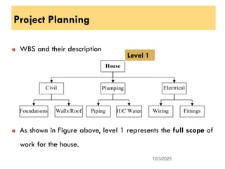
Project Planning
WBS andtheir description
As shown in Figure above, level 1 represents the full scope of
work for the house.
12/3/2025
15
Level 1
Project Planning
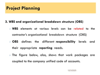
3. WBSand organizational breakdown structure (OBS)
WBS elements at various levels can be related to the
contractor’s organizational breakdown structure (OBS)
OBS defines the different responsibility levels and
their appropriate reporting needs.
The figure below, also, shows that work packages are
coupled to the company unified code of accounts.
12/3/2025
19
14.
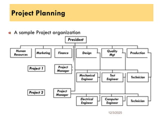
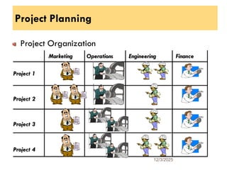
Project Planning
A sampleProject organization
12/3/2025
20
Marketing Finance
Human
Resources Design
Quality
Mgt
Production
President
Test
Engineer
Mechanical
Engineer
Project 1 Project
Manager
Technician
Technician
Project 2 Project
Manager
Electrical
Engineer
Computer
Engineer
Project Planning
Planning Steps:
4.Project Activities
An activity is defined as any function or decision in the
project that: consumes time, resources, and cost.
Activities are classified to three types:
12/3/2025
22
17.
Project Planning
a. Productionactivities: activities that involve the use of
resources such as labor, equipment, material, or
subcontractor.
This type of activities can be easily identified by reading
the project’s drawings and specifications.
Examples: excavation, formwork, reinforcement, concreting etc
Each production activity can have a certain quantity of work,
resource needs, costs, and duration. 12/3/2025
23
18.
Project Planning
b. Procurementactivities: activities that specify the time for
procuring materials or equipment that are needed for a
production activity.
Examples are: brick procurement, cement manufacturing
and delivery, etc.
c. Management activities: activities that are related to
management decisions such as approvals, vacations, etc.
12/3/2025
24
19.
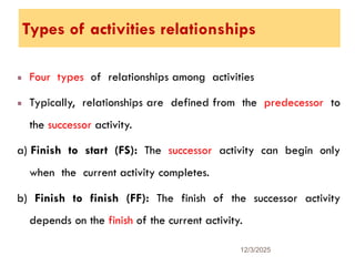
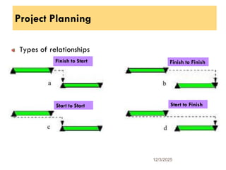
Types of activitiesrelationships
Four types of relationships among activities
Typically, relationships are defined from the predecessor to
the successor activity.
a) Finish to start (FS): The successor activity can begin only
when the current activity completes.
b) Finish to finish (FF): The finish of the successor activity
depends on the finish of the current activity.
12/3/2025
26
20.
Project Planning
Cont’d
c) Startto start (SS). The start of the successor activity depends
on the start of the current activity.
d) Start to finish (SF). The successor activity cannot finish until the
current activity starts.
12/3/2025
27
21.
Project Planning
Types ofrelationships
12/3/2025
28
Start to Finish
Start to Start
Finish to Finish
Finish to Start
22.
Project Scheduling
How longthe total project duration is?
Evaluate the early and late times at which activities start
and finish.
Identify the group of critical activities so that special care is
taken to make sure they are not delayed.
All these statements are the basic objectives of the scheduling
process,
Scheduling = Planning + Time. 12/3/2025
29
23.
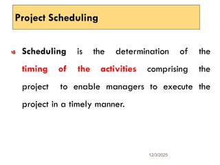
Project Scheduling
Scheduling isthe determination of the
timing of the activities comprising the
project to enable managers to execute the
project in a timely manner.
12/3/2025
30
24.
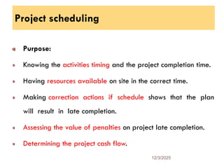
Project scheduling
Purpose:
Knowing theactivities timing and the project completion time.
Having resources available on site in the correct time.
Making correction actions if schedule shows that the plan
will result in late completion.
Assessing the value of penalties on project late completion.
Determining the project cash flow.
12/3/2025
31
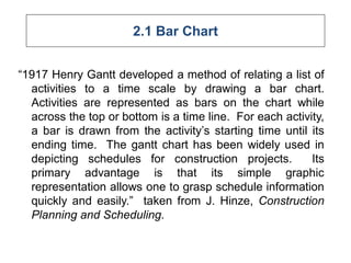
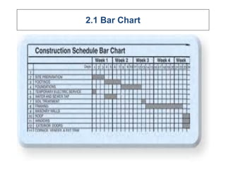
2.1 Bar Chart
“1917Henry Gantt developed a method of relating a list of
activities to a time scale by drawing a bar chart.
Activities are represented as bars on the chart while
across the top or bottom is a time line. For each activity,
a bar is drawn from the activity’s starting time until its
ending time. The gantt chart has been widely used in
depicting schedules for construction projects. Its
primary advantage is that its simple graphic
representation allows one to grasp schedule information
quickly and easily.” taken from J. Hinze, Construction
Planning and Scheduling.
27.
Cont…..
• It isone of the earliest methods for
scheduling and controlling construction
projects.
• Although severe limitations may prohibit the
widespread use of bar charts when a modern
complex structure or infrastructure is
targeted and being planned
28.
2.1 Bar Chart
•A bar chart shows the total project in a compact
format and provides the opportunity for visualizing the
plan and the progress of the project.
• Format and provides the opportunity for visualizing
the plan and the progress of the project.
29.
2.1 Bar Chart
•The bar chart is probably the best known
of all the planning techniques.
• It basically features a plan of a project
split into a logically related individual
activities each represented graphically by
scaled lines.
30.
2.1 Bar Chart
•Bar charts present the project schedule
plotted to a horizontal line scale.
• The bar lines represent the time period
allocated to each operation and the
relationship between the commencement
and completion of each can be readily
observed.
31.
2.1 Bar Chart
•The bar chart has been the traditional
management device for planning and
scheduling construction projects.
• Bar charts are particularly helpful for
communicating the current state and
schedule of activities on a project.
32.
2.1 Bar Chart
•As such, they have found wide acceptance as a
project representation tool in the field.
• For planning purposes, bar charts are not as
useful since they do not indicate the precedence
relationships among activities.
• Thus, a planner must remember or record
separately that a change in one activity's
schedule may require changes to successor
activities.
33.
2.1 Bar Chart
•There have been various schemes for
mechanically linking activity bars to
represent precedence, but it is now
easier to use computer based tools to
represent such relationships.
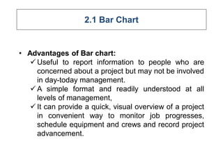
2.1 Bar Chart
•Advantages of Bar chart:
Useful to report information to people who are
concerned about a project but may not be involved
in day-today management.
A simple format and readily understood at all
levels of management,
It can provide a quick, visual overview of a project
in convenient way to monitor job progresses,
schedule equipment and crews and record project
advancement.
36.
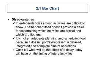
2.1 Bar Chart
•Disadvantages
Interdependencies among activities are difficult to
show. The bar chart itself doesn’t provide a basis
for ascertaining which activities are critical and
which are floaters
It is not an adequate planning and scheduling tool
because it doesn’t portray/represent a detailed,
integrated and complete plan of operations
Can't tell what will be the effect of a delay today
will have on the timing of future activities.
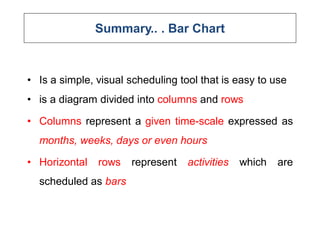
Summary.. . BarChart
• Is a simple, visual scheduling tool that is easy to use
• is a diagram divided into columns and rows
• Columns represent a given time-scale expressed as
months, weeks, days or even hours
• Horizontal rows represent activities which are
scheduled as bars
39.
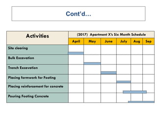
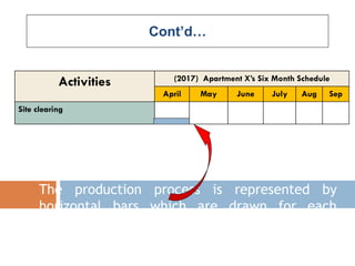
Cont’d…
Activities (2017) ApartmentX’s Six Month Schedule
April May June July Aug Sep
Site clearing
Bulk Excavation
Trench Excavation
Placing formwork for Footing
Placing reinforcement for concrete
Pouring Footing Concrete
40.
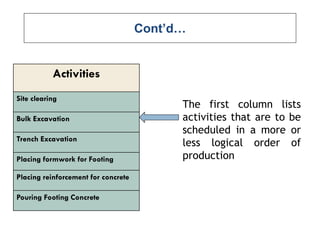
Cont’d…
Activities
Site clearing
Bulk Excavation
TrenchExcavation
Placing formwork for Footing
Placing reinforcement for concrete
Pouring Footing Concrete
The first column lists
activities that are to be
scheduled in a more or
less logical order of
production
41.
Cont’d…
Activities (2017) ApartmentX’s Six Month Schedule
April May June July Aug Sep
Site clearing
The production process is represented by
horizontal bars which are drawn for each
activity within the time-frame of the bar chart
42.
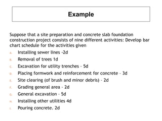
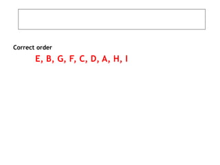
Example
Suppose that asite preparation and concrete slab foundation
construction project consists of nine different activities: Develop bar
chart schedule for the activities given
A. Installing sewer lines -2d
B. Removal of trees 1d
C. Excavation for utility trenches – 5d
D. Placing formwork and reinforcement for concrete – 3d
E. Site clearing (of brush and minor debris) – 2d
F. Grading general area – 2d
G. General excavation – 5d
H. Installing other utilities 4d
I. Pouring concrete. 2d
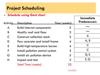
Project Scheduling
Schedule usingGant chart
12/3/2025
52
Activity Description Time (weeks)
A Build internal components 2
B Modify roof and floor 3
C Construct collection stack 2
D Pour concrete and install frame 4
E Build high-temperature burner 4
F Install pollution control system 3
G Install air pollution device 5
H Inspect and test 2
Total Time (weeks) 25
Immediate
Predecessors
—
—
A
A, B
C
C
D, E
F, G
45.
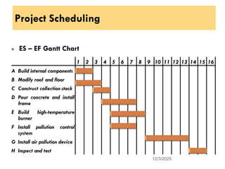
Project Scheduling
ES –EF Gantt Chart
12/3/2025
53
A Build internal components
B Modify roof and floor
C Construct collection stack
D Pour concrete and install
frame
E Build high-temperature
burner
F Install pollution control
system
G Install air pollution device
H Inspect and test
1 2 3 4 5 6 7 8 9 10 11 12 13 14 15 16
46.
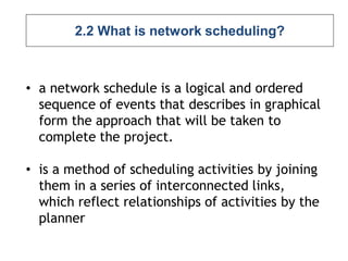
2.2 What isnetwork scheduling?
• a network schedule is a logical and ordered
sequence of events that describes in graphical
form the approach that will be taken to
complete the project.
• is a method of scheduling activities by joining
them in a series of interconnected links,
which reflect relationships of activities by the
planner
47.
Cont’d…
• A networkconsists of two basic
elements, nodes, and links between the
nodes.
• Networks are used as scheduling tools
for effective construction management.
• A network schedule provides many
opportunities for construction managers.
48.
Cont’d…
• It representsa mathematical model for
showing the progress of construction
activities over time
• It also provides a means to do “what-if”
analysis, where the user can change one part
of the process and observe the effect on the
overall project.
49.
Basic Assumptions inNetwork Scheduling
1. The project can be broken down into a
group of activities
2. Each activities can be assigned a
duration
3. The logical relationship among
activities are known and fixed in the
network chains
50.
Rules for Preparingthe Network Diagram
1. No activity can start before the preceding activity
is finalized
2. There is only one start and finish for an activity
3. No activity leads back and forms a loop
4. The logical precedence, concurrent/parallel and
subsequent/following activities must be clearly
developed
5. A Dummy activity is established only to show
relationship. A dummy activity is assumed to
have duration of ZERO time units and it is
introduced on the network when it is necessary
51.
Presentation of Networks
•Showing the job activities and their order of
sequence (logic) in pictorial form produces
the project network.
• This network is a graphical display of the
proposed plan.
• There are two methods. These are: -
52.
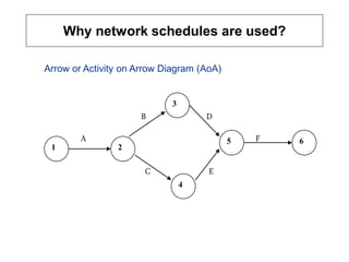
Why network schedulesare used?
B D
A F
C E
1 2
6
5
4
3
Arrow or Activity on Arrow Diagram (AoA)
53.
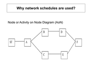
Why network schedulesare used?
Node or Activity on Node Diagram (AoN)
ST F
E
D
C
B
A
54.
Why network schedulesare used?
Network Logic:
Network logic refers to the determined order in
which the activities are interrelated in order to
accomplish the task.
Identifying the preceding activity and immediately
preceding activity (IPA) is the easiest method to
develop the network logic and draw the network
diagram.
55.
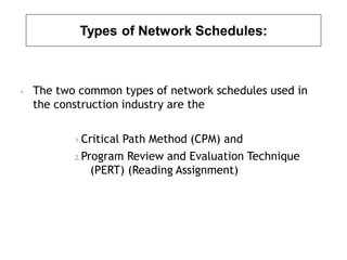
Types of NetworkSchedules:
• The two common types of network schedules used in
the construction industry are the
1.Critical Path Method (CPM) and
2.Program Review and Evaluation Technique
(PERT) (Reading Assignment)
56.
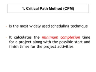
1. Critical PathMethod (CPM)
• Is the most widely used scheduling technique
• It calculates the minimum completion time
for a project along with the possible start and
finish times for the project activities
57.
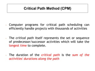
Critical Path Method(CPM)
• Computer programs for critical path scheduling can
efficiently handle projects with thousands of activities
• The critical path itself represents the set or sequence
of predecessor/successor activities which will take the
longest time to complete.
• The duration of the critical path is the sum of the
activities' durations along the path
58.
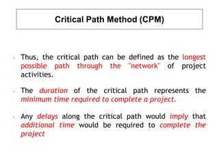
Critical Path Method(CPM)
• Thus, the critical path can be defined as the longest
possible path through the "network" of project
activities.
• The duration of the critical path represents the
minimum time required to complete a project.
• Any delays along the critical path would imply that
additional time would be required to complete the
project
59.
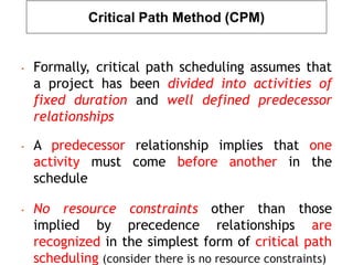
Critical Path Method(CPM)
• Formally, critical path scheduling assumes that
a project has been divided into activities of
fixed duration and well defined predecessor
relationships
• A predecessor relationship implies that one
activity must come before another in the
schedule
• No resource constraints other than those
implied by precedence relationships are
recognized in the simplest form of critical path
scheduling (consider there is no resource constraints)
60.
Critical Path Method(CPM) {see examples}
Precedence Relations for a Nine-Activity Project Example
Activity Description Predecessors
A
B
C
D
E
F
G
H
I
Site clearing
Removal of trees
General excavation
Grading general area
Excavation for utility trenches
Placing formwork and reinforcement
Installing sewer lines
Installing other utilities
Pouring concrete
---
---
A
A
B,C
B,C
D,E
D,E
F,G
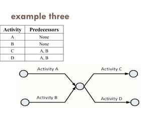
Dummy Activity
Thisactivity does not involve consumption of resources, and
therefore does not need any time to be ‘completed’.
It is used to define interdependence between activities and
included in a network for logical and mathematical reasons as
will be shown later.
Illustration of event, activity, and dummy activity
72
10 30 50
20 40 60
A B
C D
E
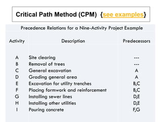
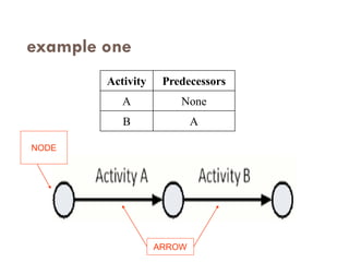
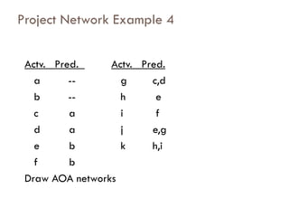
A project hasthe following activities and precedence
relationships:
Actv. Pred. Actv. Pred.
a -- f c,e
b a g b
c a h b,d
d a i b,d
e b j f,g,h
Draw AOA
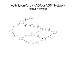
Project Network Example 5
Example-6
For the projectindicated below, Develop a clear logic network for the activities.
a. AOA
b. AON
72.
Project Scheduling [CPM]
AOAExample
12/3/2025
80
Activity Description
Immediate
Predecessors
A Build internal components —
B Modify roof and floor —
C Construct collection stack A
D Pour concrete and install frame A, B
E Build high-temperature burner C
F Install pollution control system C
G Install air pollution device D, E
H Inspect and test F, G
73.
Project Scheduling [CPM]
AOANetwork
12/3/2025
81
1
3
2
5
D
(Pour Concrete/
Install Frame)
4
C
(Construct
Stack)
Dummy
Activity
6
H
(Inspect/
Test)
7
74.
Project Scheduling [CPM]
AONNetwork
12/3/2025
82
A
Start
B
Activity A
(Build Internal Components)
Activity B
(Modify Roof and Floor)
75.
Project Scheduling [CPM]
AONNetwork
12/3/2025
83
A
Start
B
C
D
activity A precedes activity C
activities A and B
precede activity D

![Project Planning
Planning Steps:
2. Work Breakdown Structures [WBS]
WBS is a hierarchical structure which is designed to
logically sub-divide all the work-elements of the project into
a graphical presentation.
The full scope of work for the project is placed at the
top of the diagram, and then sub-divided smaller
elements of work at each lower level of the breakdown.
12/3/2025
12](https://image.slidesharecdn.com/chapter4planningandscheduling184-251215174100-dbc06a4d/85/Chapter-4-Planning-and-Scheduling-1_84-pdf-9-320.jpg)
![Project Planning
WBS: Level
1. Project
2. Major tasks in the project
3. Subtasks in the major responsibilities
4. Activities [or work packages] to be completed
12/3/2025
14](https://image.slidesharecdn.com/chapter4planningandscheduling184-251215174100-dbc06a4d/85/Chapter-4-Planning-and-Scheduling-1_84-pdf-10-320.jpg)
![Project Scheduling [CPM]
AOA Example
12/3/2025
80
Activity Description
Immediate
Predecessors
A Build internal components —
B Modify roof and floor —
C Construct collection stack A
D Pour concrete and install frame A, B
E Build high-temperature burner C
F Install pollution control system C
G Install air pollution device D, E
H Inspect and test F, G](https://image.slidesharecdn.com/chapter4planningandscheduling184-251215174100-dbc06a4d/85/Chapter-4-Planning-and-Scheduling-1_84-pdf-72-320.jpg)
![Project Scheduling [CPM]
AOA Network
12/3/2025
81
1
3
2
5
D
(Pour Concrete/
Install Frame)
4
C
(Construct
Stack)
Dummy
Activity
6
H
(Inspect/
Test)
7](https://image.slidesharecdn.com/chapter4planningandscheduling184-251215174100-dbc06a4d/85/Chapter-4-Planning-and-Scheduling-1_84-pdf-73-320.jpg)
![Project Scheduling [CPM]
AON Network
12/3/2025
82
A
Start
B
Activity A
(Build Internal Components)
Activity B
(Modify Roof and Floor)](https://image.slidesharecdn.com/chapter4planningandscheduling184-251215174100-dbc06a4d/85/Chapter-4-Planning-and-Scheduling-1_84-pdf-74-320.jpg)
![Project Scheduling [CPM]
AON Network
12/3/2025
83
A
Start
B
C
D
activity A precedes activity C
activities A and B
precede activity D](https://image.slidesharecdn.com/chapter4planningandscheduling184-251215174100-dbc06a4d/85/Chapter-4-Planning-and-Scheduling-1_84-pdf-75-320.jpg)
![Project Scheduling [CPM]
AOM Network
12/3/2025
84
C
A
Start
D
B G
E
F
H
Arrows Show Precedence
Relationships](https://image.slidesharecdn.com/chapter4planningandscheduling184-251215174100-dbc06a4d/85/Chapter-4-Planning-and-Scheduling-1_84-pdf-76-320.jpg)


