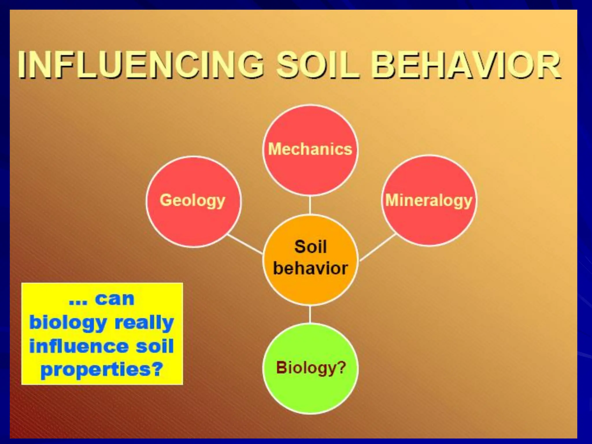
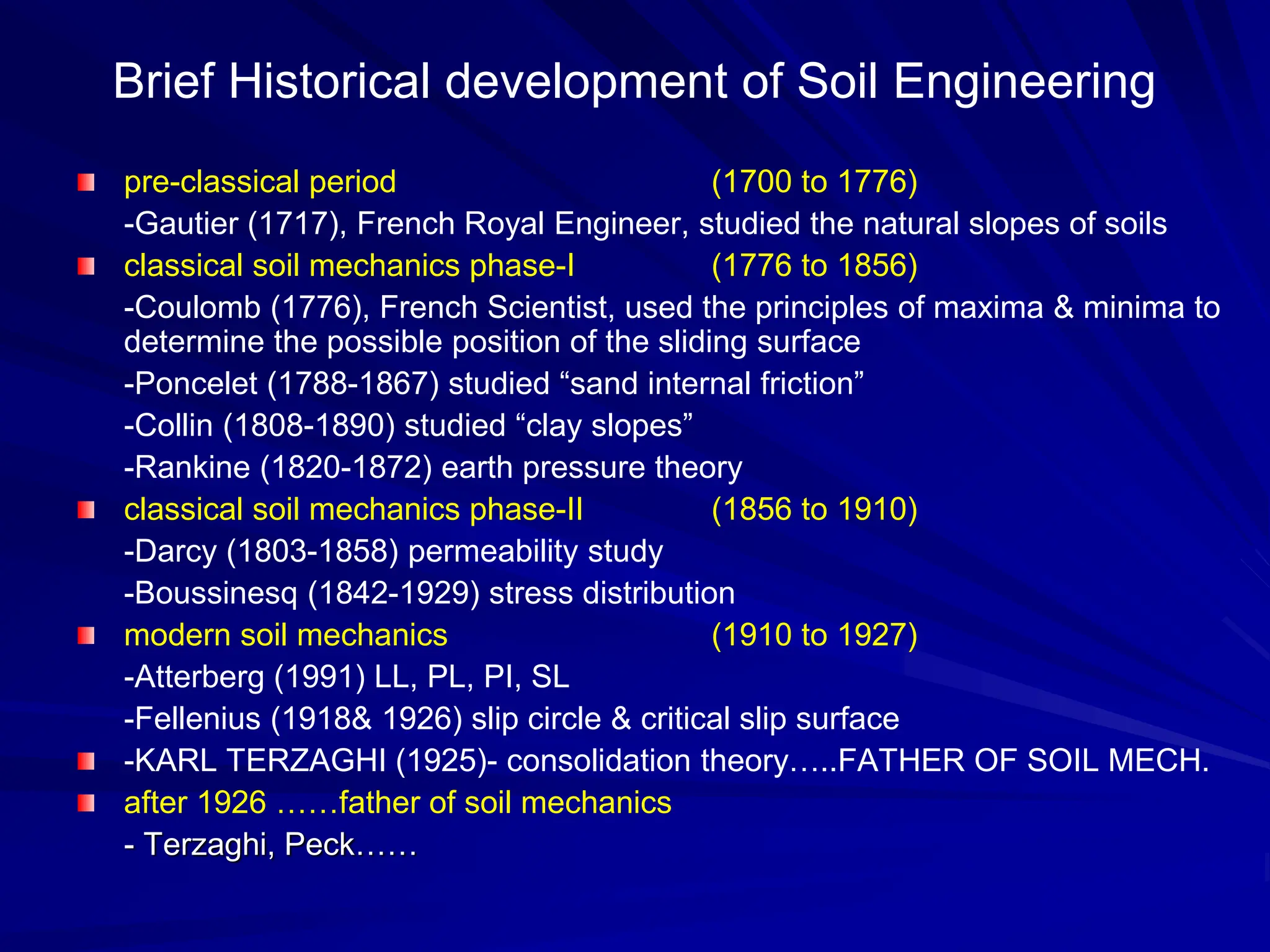
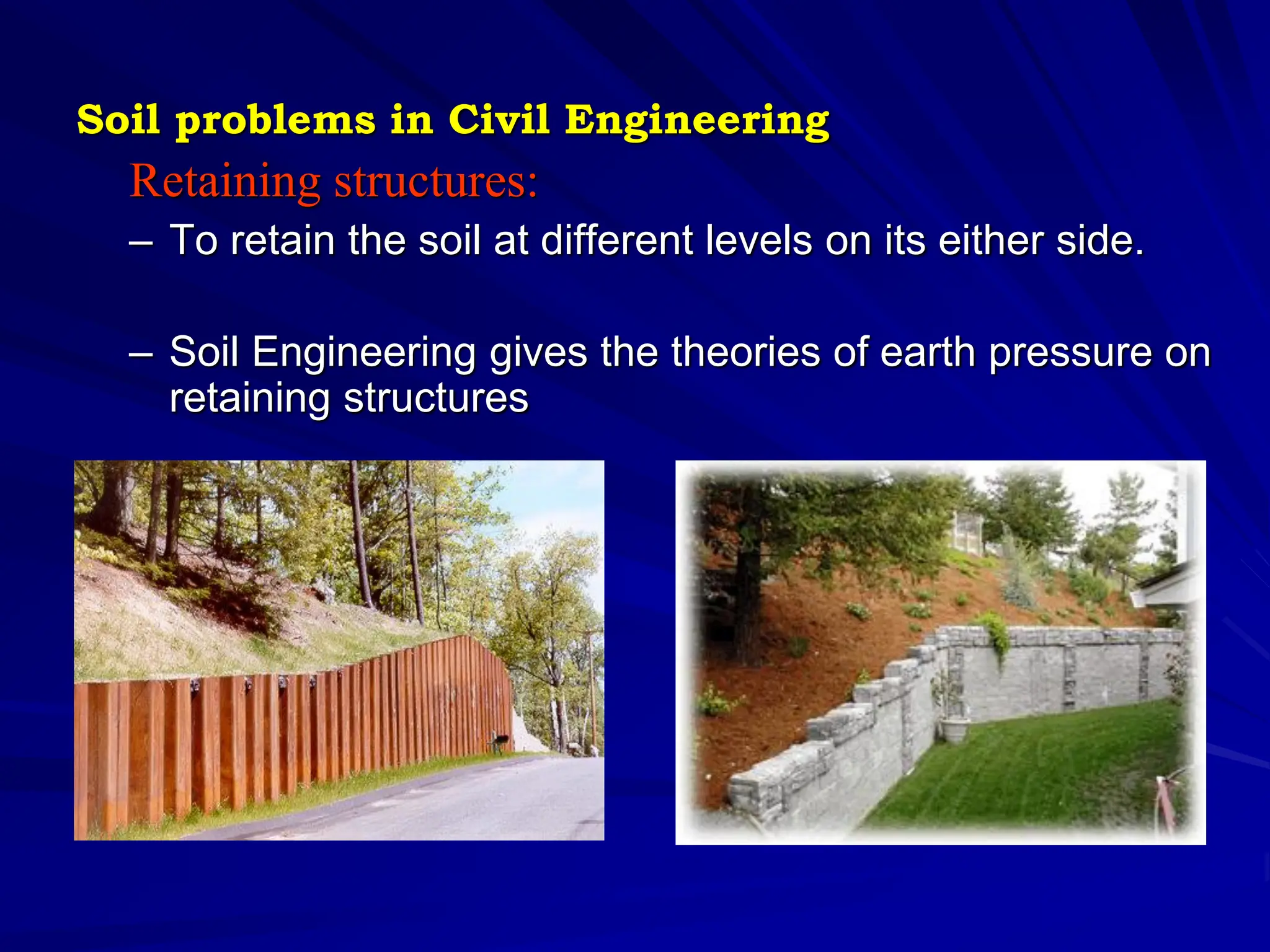
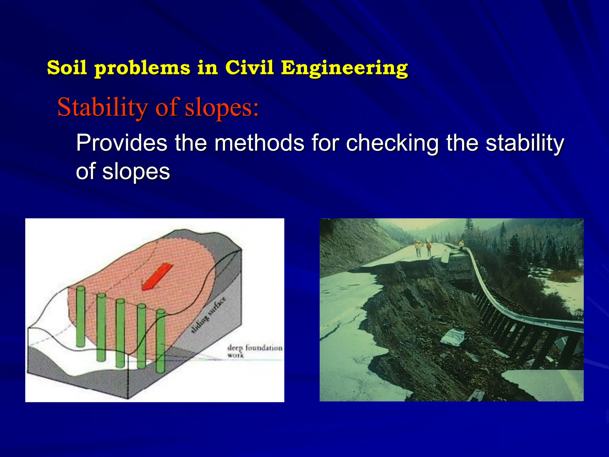
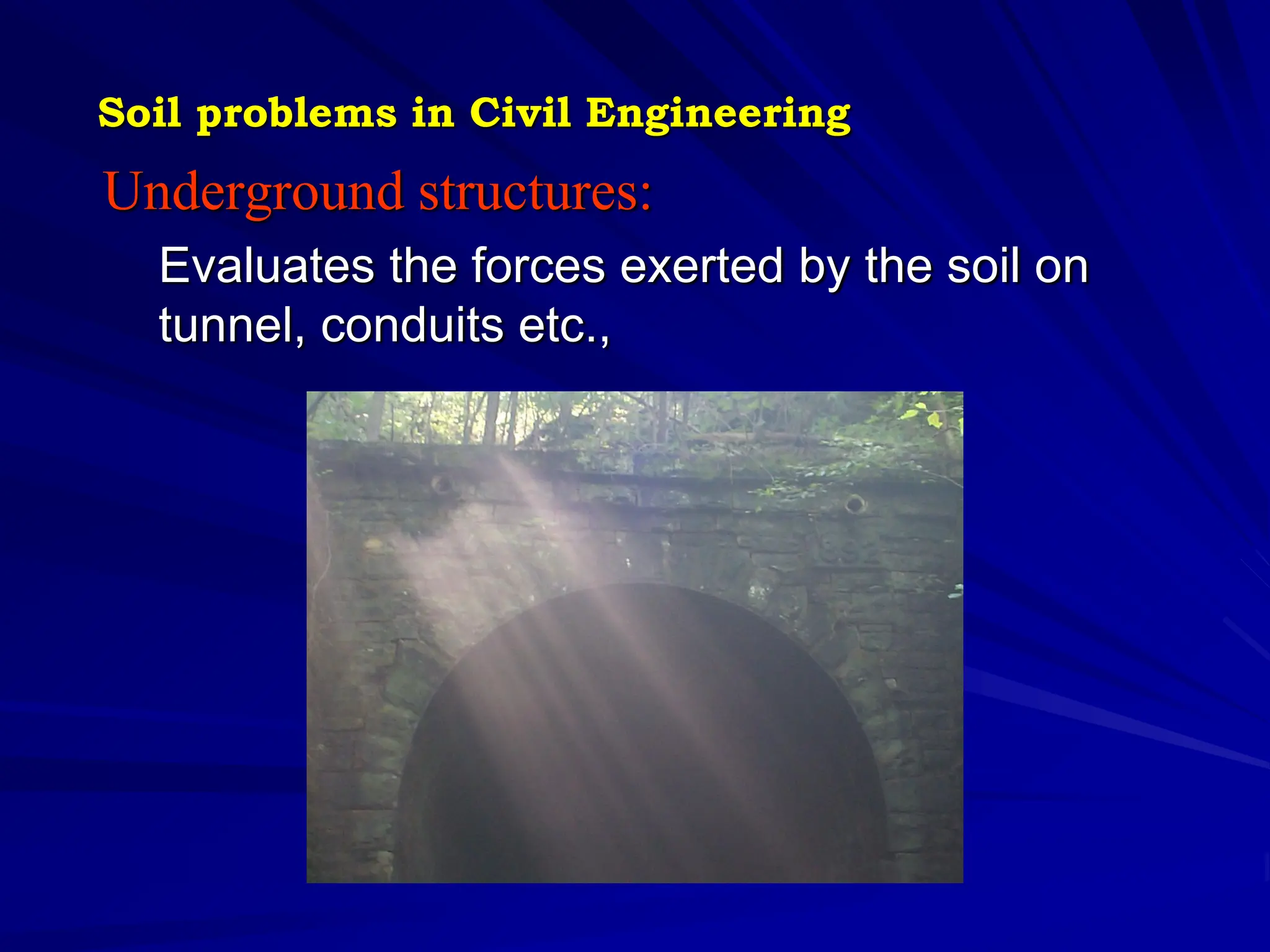
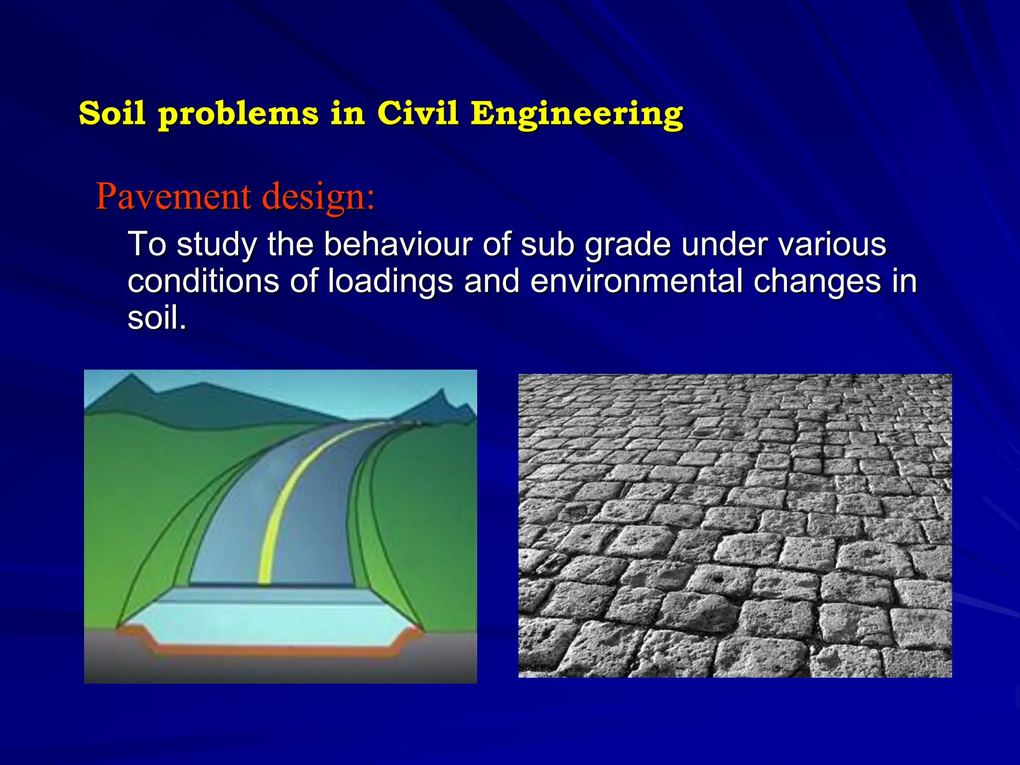
COURSE PLAN AND CONTENT
COURSE : CEPC16 GEOTECHNICAL ENGINEERING – I
Faculty Coordinator:
Dr. K. Muthukkumaran
Department of Civil Engineering
National Institute of Technology
Tiruchirappalli
Email : kmk@nitt.edu
Telephone : 91-431-2503168
Mobile: 9443651836
Objective of the course
 To explain what Geotechnical Engineering is
and how it is important to civil engineering
 To explain how three phase system is used in
soil and how soil properties are estimated using
three phase system
 To explain role of water in soil behaviour and
how soil stresses, permeability and quantity of
seepage including flow net are estimated
 To determine shear parameters and stress
changes in soil due to foundation loads
 To estimate the magnitude and time-rate of
settlement due to consolidation
Outcome of the course
 Understand the importance of geotechnical
engineering in civil engineering
 Do proper soil classification and three phase
system to solve the problems
 Solve any practice problems related to soil
stresses estimation, permeability, seepage
including flow net diagram.
 Do proper stress estimation under any system of
foundation loads
 Solve any practical problems related to
consolidation like consolidation settlement, time
rate of settlement
SOIL MECHANICS
Soil mechanics is a branch of mechanics which
deals with the action of forces on soil and with the
flow of water in soil
1. INTRODUCTION TO SOIL MECHANICS (9 lectures)
1.1 Brief Historical development of Soil Engineering
pre-classical period (1700 to 1776)
classical soil mechanics phase-I (1776 to 1856)
classical soil mechanics phase-II (1856 to 1910)
modern soil mechanics (1910 to 1927)
after 1926 ……father of soil mechanics KARL TERZAGHI- consolidation theory ….followed by
Ralph Peck and etc……
1.2 Soil Problems in Engineering
foundation design and construction
pavement design
design of underground and earth retaining structures
design of embankments and excavations
design of earth dams
1.3 Origin and General Types of Soils
Soil formation – geological cycle (Igneous, metamorphic & sedimentary rocks ……gravel, sand,
mud and other sediments due to weathering….)
soil types: (1) Residual soils (2) transported soils (3)Desiccated soils
T.S…water transported soil….alluvial deposit, marine deposit,
T.S…wind transported soil…aeolian deposits, Gravity deposits….Talus,
Swamp and march deposits
Major soil deposits in India
Marine deposits, Black cotton soils, laterItes soils Lateritic soils (residual soils), Alluvial deposits
and Desert soils
1.4 Soil Structure
Components of Soils: Solid phase, liquid phase and gaseous phase
Particle Size: Cobbles or Pebbles, Gravel, sand, silt and clay
Granular soil: Angular, sub angular, sub rounded, rounded, well rounded
Soil-Structure: Single grained, Honeycomb, flocculent and dispersed
1.5 Clay Minerals
Inter-particle forces: attractive forces & repulsive forces
Clay mineral structures: Tetrahedral & Octahedral (silica sheet & Alumina…Gibbsite sheet or
magnesium Brucite Sheet)
Clay mineral: Kaolinite, Montmorillonite and illite
1.6 Weight Volume Relationship
Volume relationships: Void ratio(e); Porosity(n); Degree of saturation(S)
Weight relationship: Moisture content or Water content(w); Unit weight(γ)
Relative density: based on void ratio & densities
Consistancy of soil: LL, PL, PI, SL, LI, A & plasticity chat
1.7 Identification and Classification of Soil
Field identification of soils: Coarse grained & fine grained soils
gravel & sand silt & clay (organic/inorganic)
Engineering Classifications: Unified soil classification system
Indian soil classification system
AASHTO soil classification system
Textural soil classification system
References
1. Gopal Ranjan and Rao, P. Basic and Applied Soil Mechanics, New Age International Pvt.
Limited, New Delhi, 2002.
2. Murthy, V.N.S., A text book of Soil Mechanics and Foundation Engineering, UBS
Publishers Distributors Ltd., New Delhi, 1999
3. Punmia, B.C. Soil Mechanics and Foundation Engineering, Laxmi Publications Pvt. Ltd.,
New Delhi, 1995.
4. Braja M. Das, Fundamentals of Geotechnical Engineering, Thomson Asia Pvt. Ltd.,
Singapore, 2005.
2. SOIL WATER (8 lectures)
2.1 Capillary Phenomena
Surface tension
Capillary phenomena in soils: hcr=c/eD10 c=0.01x10⁻³ to 0.05x10⁻³ m2
2.2 Concept of Effective and Neutral Stresses
Stress conditions in soil: effective & neutral stress
Different cases: submerged soil; soil mass with surcharge; saturated soil with capillary raise
2.3 Permeability
Darcy’s law q=kia
Laboratory permeability tests: Constant head (q=Ak(h/l)) &
falling head k=2.303(al/At)log10(h1/h2)
Field permeability test
Factors affecting permeability: soil characteristics & pore fluid characteristics
2.4 Seepage Flow
Seepage force: Quick sand; upward flow
Two dimensional flow: Laplace equation
2.5 Flow Net
Properties of flow net
Applications of flow net
Construction of flow net: boundary conditions
Construction methods:
References
1. Gopal Ranjan and Rao, P. Basic and Applied Soil Mechanics, New Age International Pvt.
Limited, New Delhi, 2002.
2. Murthy, V.N.S., A text book of Soil Mechanics and Foundation Engineering, UBS, Publishers Distributors Ltd., New Delhi, 1999
3. Punmia, B.C. Soil Mechanics and Foundation Engineering, Laxmi Publications Pvt. Ltd., New Delhi, 1995.
4. Braja M. Das, Fundamentals of Geotechnical Engineering, Thomson Asia Pvt. Ltd., Singapore, 2005.
3. STRESS DISTRIBUTION AND COMPACTION (8 lectures)
3.1 Vertical Stress Distribution
Stress at a point
Mohr’s circle
Stress path
Effective stress concept
elastic properties of soil
3.2 Boussinesq and Westergaard’s Equations
Boussinesq theory: pressure distribution diagrams
Westergaard’s equation: types of surface loads
3.3 Newmark’s Influence Chart - Principle, Construction and Use
3.4 Equivalent Point Load and other Approximate Methods
3.5 Pressure Bulb
3.6 Compaction
principles of compaction
compactive effort
laboratory compaction: standard proctor test; modified proctor test
field compaction equipment
factor affecting compaction
effect of compaction on soil structure
4. SHEAR STRENGTH (9 lectures)
4.1 Mohr-Coulomb Failure Criterion
stress-strain curve
Mohr-Coulomb failure criteria
4.2 Shear Strength Test
direct shear test
triaxial shear test
UCC test
vane shear test
4.3 Different Drainage Conditions
Drainage conditions (UU, CU, CD)
4.4 Shear Properties of Cohesionless and Cohesive Soils
c & φ
Sensitivity & Thixotrophy of clay
4.5 Use of Mohr’s Circle
4.6 Relationship between Principal Stresses and Shear Parameters
5. COMPRESSIBILITY AND CONSOLIDATION (7 lectures)
5.1 Terzaghi’s One Dimensional Consolidation Theory
piston & Spring analogy
Consolidation of laterally confined soil
5.2 Pressure Void Ratio Relationships
Laboratory consolidation test:
void ratio vs coefficient of volume change
Compression index
coefficient of consolidation & k
degree of consolidation
type of clay deposit (NCC, OCC & UCC)
5.3 Pre-Consolidation Pressure
5.4 Total Settlement and Time Rate of Settlement
Rate of consolidation
immediate settlement
consolidation settlement: primary compression & secondary compression
5.5 Coefficient of Consolidation
determination of cv by square root method and logarithm of time fitting method
5.6 Curve Fitting Methods
5.7 Correction for Construction Time
Construction period correction
acceleration of consolidation by sand drains
For engineering purposes, soil is defined as the
uncemented aggregate of mineral grains and
decayed organic matter with liquid and gas in the
empty spaces between the solid particles.
Prior to 18th century
Nile (Egypt)
Tigris and Euphrates (mesopotamia)
Huang Ho (yellow river, China)
Indus (India)
- Leaning Tower of Pisa in Italy (1173)
- Bologna Tower in Italy 12th century
pre-classical period (1700 to 1776)
-Gautier (1717), French Royal Engineer, studied the natural slopes of soils
classical soil mechanics phase-I (1776 to 1856)
-Coulomb (1776), French Scientist, used the principles of maxima & minima to
determine the possible position of the sliding surface
-Poncelet (1788-1867) studied “sand internal friction”
-Collin (1808-1890) studied “clay slopes”
-Rankine (1820-1872) earth pressure theory
classical soil mechanics phase-II (1856 to 1910)
-Darcy (1803-1858) permeability study
-Boussinesq (1842-1929) stress distribution
modern soil mechanics (1910 to 1927)
-Atterberg (1991) LL, PL, PI, SL
-Fellenius (1918& 1926) slip circle & critical slip surface
-KARL TERZAGHI (1925)- consolidation theory…..FATHER OF SOIL MECH.
after 1926 ……father of soil mechanics
- Terzaghi, Peck……
Brief Historical development of Soil Engineering
Soil problems in Civil Engineering
 Foundations
 Retaining structures
 Stability of slope
 Underground structure
 Pavement design
 Earth dam
Foundations:
To transmit the load of the structures to soil safely and
efficiently.
Deep Foundation Shallow Foundation
Soil problems in Civil Engineering
Retaining structures:
– To retain the soil at different levels on its either side.
– Soil Engineering gives the theories of earth pressure on
retaining structures
Soil problems in Civil Engineering
Stability of slopes:
Provides the methods for checking the stability
of slopes
Soil problems in Civil Engineering
Underground structures:
Evaluates the forces exerted by the soil on
tunnel, conduits etc.,
Soil problems in Civil Engineering
Pavement design:
To study the behaviour of sub grade under various
conditions of loadings and environmental changes in
soil.
Soil problems in Civil Engineering
Rock Forming Minerals
Minerals are naturally formed elements or
compounds with specific structures and
chemical compositions.
More then 2000 different minerals are
present in the earth’s crust
COMMON MINERALS
Feldspar
– Contain sodium, calcium or both
– Colour range from white to gray to black
– Moderate hardness
Quartz
– Silicate
– Milky white colour
– Very hard
Ferromagnesiam
– Contain both iron and magnesium
– Dark colour
– Moderate hardness
Iron oxides
– Contain iron oxide
– Rusty colour
– Act as cementing agents
Calcite
– Calcium carbonate
– White, pink or gray
– Soluble in water
– Act as cementing agents
Dolomite
– Similar to calcite with magnesium added
Mica
– Translucent thin sheet or flakes
– Muscovite has silvery flakes, white biotite is dark gray or black
– Low friction, lead to shear failure
Gypsum
– Soft mineral, precipitate in sedimentary rocks
– Colourless to white
– Water soluble
Origin and General Types of Soils
Soil formation – geological cycle (Igneous, metamorphic & sedimentary
rocks ……gravel, sand, mud and other sediments due to
weathering….)
1-heat, pressure & solution
2-melting of deeply buried rocks
3-weathering, deposition and
consolidation
4-weathering
5-erosion and weathering
6-compaction & consolidation
Igneous Rock Sedimentary
Rock
Metamorphic
Gravel, Sand,
Mud and other
sediments
1
5
5
4
3
2
1
6
7-Possible of melting of deep rock
Weathering processes
The erosive action of water, ice and wind
Chemical reaction induced by exposure to
oxygen, water, and chemicals
Loosening through the growth of plant roots
Freezing of water
Growth of minerals in the cracks
Thermal expansion and contraction
Landslides and rock falls
Sinkhole in Winter Park, Florida May 8, 1981,
75m in diameter
SEDIMENTARY
ROCKS
SOIL TYPES
SOIL TYPES:
(1) Residual soils
(2) Transported soils
Residual soils: when rock weathering process is
faster then the transport processes induced by
water, wind and gravity, much of the resulting
soil remains in place is known as residual soils.
Sandy residual soil: decomposed granite-high
quality
Laterite: residual soil found in tropical region
Transported soils
Glacial soils
Alluvial soils
Lacustrine and marine soils
Aeolian soils
Colluvial soils
Glacial soil
Till – is soil deposited directly by the glacier
Soil caught beneath the glacier-lodgement till-
highly consolidated under the weight of ice-
provide very good support for structures
When the glaciers melted, they generated large
quantities of runoff. This water eroded much of
the till and deposited it downstream, forming
glaciofluvial soils.
The fine soils of the till often remained
suspended inn the runoff water until reaching a
lake or ocean, where it finally settled to the
bottom- glaciolacustrine / glaciomarine soils
Glacial soils
Alluvial soils ( fluvial / alluvium)
Transported to the present position by rivers and
streams
Alluvial fans- water flow will be slow when the
stream reaches the foot of a canyon, and tends
to deposit much of its soil load there
Rivers in relatively flat terrain move much more
slow and often change course, creating complex
alluvial deposits. – braided stream deposits
meander belt deposits
Cementing agent – calcium carbonate, calcium
sulfate – form hard materials called caliche
Alluvial soils
Lacustrine and marine soils
Lacustrine soils are those deposited beneath
lakes
Mostly silt and clay
Suitability for foundation support ranges from
poor to average
Marine soils also were deposited underwater,
except they formed in the ocean
Deeper marine deposits are uniform and often
contain organic material from marine organisms
Lacustrine soils
Aeolian soils
Aeolian soils are those deposited by wind
Produces very poorly graded soils (
uniform size, narrow range)
Mode of wind induced soil transport
– Suspension (silt and clay, high altitudes,
create large dust storms)
– Saltation (particles temporarily airborne)
– Creep (rolling and sliding)
Aeolian soils
Aeolian soils
landslide
Colluvial soils
Major soil deposits of India
The soil deposits of India can be broadly classified
into the following five types
1. Block cotton soils, occurring in maharashtra,
Gujarat, Madhya Pradesh, karnataka, part of
Andhra Pradesh and Tamil Nadu.
2. Marine Soils, occurring in a narrow belt all along
the coast, especially in the Rann of Kutch.
3. Desert soils, occurring in Rajasthan.
4. Alluvial soils, occurring in the Indo-Gangetic
plain, north of the Vindhyachal ranges.
5. Lateritic soils, occurring in kerala, south
Maharashtra, karnataka, Orissa and West
Bengal.
Soil Structure
Components of Soils:
Solid phase, liquid phase and gaseous phase
Particle Size: Cobbles or Pebbles, Gravel,
sand, silt and clay
Granular soil: Angular, sub angular, sub
rounded, rounded, well rounded
Soil-Structure: Single grained, Honeycomb,
flocculent and dispersed
Single-grained soil
Characteristic of coarse-grained soils, with a
particle size greater than 0.02mm.
Gravitational forces predominate the surface
forces and hence grain to grain contact results.
The deposition may occur in a loose state, with
large voids or in a dense state, with less of voids.
Single-grained soil
Honey-comp structure
This structure can occur only in fine-grained soils,
especially in silt and rock flour.
Gravitational forces, inter-particle surface forces
also play an important role in the process of settling
down.
Miniature arches are formed, which bridge over
relatively large void spaces.
Honey-comb being made up of numerous
individual soil grains.
The structure has a large void space and may
carry high loads.
 The structure can be broken down by external
disturbances.
Honey-comp structure
Flocculent structure
This structure is characteristic of fine-grained soils,
such as clays.
Inter-particle surface forces play a predominant
role in the deposition.
Mutual repulsion of the particles may be eliminated
by means of an appropriate chemical; this will result
in grains coming closer together to form a ‘floc’.
The formation of flocs is ‘flocculation’.
Flaky particles of clay minerals tend to form a card
house structure, when flocculated.
 In practice, mixed structures occur, especially in
typical marine soils.
Flocculent structure
Card-house structure
of flaky particles
Dispersed structure
Soil Texture
Texture indicates the relative content of particles
of various sizes, such as sand, silt and clay in the
soil.
Texture influences the ease with which soil can
be worked, the amount of water and air it holds,
and the rate at which water can enter and move
through soil.
To find the texture of a soil sample, first separate
the fine earth, all particles less than 2 mm, from
larger particles such as gravel and stones. Fine
earth is a mixture of sand, silt and clay.
Separation of fine earth
Quick field tests to determine soil texture
(Throw-the-ball test)
•Take a handful of moist soil and
squeeze it into a ball;
•Throw the ball into the air about
50 cm and then catch it ...
•If the ball falls apart, it is poor soil
with too much sand;
•If the ball sticks together, it is
probably good soil with enough
clay in it.
Particle shape
Particle shape is an important property in detrital sediments.
The initial shape of weathered particles is affected by
mineralogy: mica tend to platy, feldspars are often tabular, quartz
tends to be equant. Ellipsoidal, cylindrical and spherical particles
are generated by abrasion.
With increased transport distances, particles become abraded
and rounded.
Water is the most effective transport medium for rounding
particles.
Wind abrasion can also generate near spherical particles.
Ice transport can sometimes carry particles over large distance
with little or no abrasion.
Particle shape
Particle shape
Particle shape
Clay Minerals
Inter-particle forces:
– attractive forces & repulsive forces
Clay mineral structures:
– Tetrahedral & Octahedral (silica sheet & Alumina…Gibbsite sheet or
magnesium Brucite Sheet)
Clay mineral:
Montmorillonite
Kaolinite
illite
Exchangeable ions
Non-exchangeable ions
Weight Volume Relationship
Volume relationships:
– Void ratio(e);
– Porosity(n);
– Degree of saturation(S)
Weight relationship:
– Moisture content or Water content(w);
– Unit weight(γ)
Relative density:
– based on void ratio & densities
Consistancy of soil:
– LL, PL, PI, SL, LI, A & plasticity chat
PROPERTIES OF SOIL(CONTD…)
Index properties: Three Phase system
Water content: (w)
Ratio of weight of water(Ww) to weight of solids (Wd) in a given
mass of soil
W = ( Ww / Wd ) X 100
Voids ratio: (e)
Ratio of volume of voids to volume of soil solids
e = Vv / Vs
Porosity: (n)
Ratio of volume of voids to total volume of given soil mass
n = Vv / V
Index properties
Index properties
Specific gravity: (G)
Ratio of unit weight of soil solids to that of water
Specific Gravity G = s / w
Density: ()
– Mass of soil per unit total volume
– Mass density  = M / V
– Measurements taken in the field are mostly to
determine density/unit weight
Methods:
– Core Cutter Method
– Sand-Pouring Cylinder Method
Index properties
Degree of saturation: (Sr)
– Ratio of volume of water present in a given soil mass to the total
volume of voids in it.
Sr = Vw / Vv
Relative density: (ID)
– Loosest and densest states of soil is expressed in terms of relative
density.
Dr = ( max / n) X (n - min) / ( max – min)
Dr =( emax-e)/(emax-emin)
- Expressed in terms of percentage
Index properties
Index properties
Consistency:
Ease with which soil can be deformed.
Consistency Limits or Atterberg Limits:
Liquid limit (WL)
Plastic limit (WP)
Shrinkage limit (WS)
Liquid Limit: (WL)
Minimum water content at which soil
is still in liquid state.
Measured by using Casagrande’s
Apparatus
Plastic limit: (WP)
Water content below which soil stops
behaving as a plastic material
Shrinkage limit: (WS)
Smallest water content at which soil
is saturated.
Index properties
Sieve analysis (IS-2720-PART-4-1985)
Consists of shaking the soil sample
through a set of sieves that have
progressively smaller openings.
U.S. standard sieve numbers and the
sizes of openings are given :
To conduct a sieve analysis, one must first oven-dry the soil and then break
all lumps into small particles.
The soil then is shaken through a stack of sieves with openings of
decreasing size from top to bottom (a pan is placed below the stack)
Particle-size distribution curve—
sieve analysis and hydrometer
analysis
A particle-size distribution curve
used to determine the following four
parameters for soil
Parameter Descriptions
Effective size
(D10)
curve corresponding to 10% finer. The effective size
of a granular
soil is a good measure to estimate the hydraulic
conductivity and drainage
through soil.
Uniformity coefficient
(Cu)
Cu = D60 / D10
Coefficient of gradation
(Cc)
Cc =
D30^ 2 / D60 D10
Sorting coefficient
(So)
This parameter is another measure of uniformity and
is generally encountered in geologic works
Different types of particle-size distribution curves
Relative density
used to indicate the in situ denseness or
looseness of granular soil. It is defined as
Relative density ( % ) Description of Sample
deposit
0-15 Very loose
15-50 Loose
50-70 Medium
70-85 Dense
85-100 Very dense
Atterberg limit :
Clay minerals are present  fine-grained
soil remolded presence of some moisture
 without crumbling.
Cohesive nature is caused  adsorbed
water surrounding  clay particles.
In the early 1900s, a Swedish scientist
named Atterberg developed  method to
describe the consistency of fine-grained
soils  varying moisture contents
four basic states—solid, semisolid, plastic, and liquid
moisture content soil behavior
very low like a solid
Very high may flow like a liquid
Atterberg
Stated that depending on the water
content, soil may appear in four states:
Solid (no water)
semi-solid (brittle, some water)
plastic (moldable)
liquid (fluid)
In each state the consistency and
behavior of a soil is different and thus
so are its engineering properties.
The boundary between each state can
be defined based on a change in the
soils behavior.
Atterberg Limits
(Non-Plastic )
Wpl wll
Plastic Limit Liquid Limit
Water Content
w%=0
Solid Liquid
Plastic
Brittle
Atterberg limit Descriptions
Plastic limit Moisture content that defines where the soil
changes from a semi-solid to a plastic
(flexible) state.
The plastic limit is the
lower limit of the plastic stage of soil.
(thread of approximately 3mm in dia)
Lowest w/c where the
clay is still plastic (Wp or
PL)
Liquid limit Moisture content @ 25th blow Clay flows like liquid
w>LL
Shrinkage limit Soil shrinks as moisture is gradually lost from
it. With continuing loss of moisture, a stage of
equilibrium is reached at which more loss of
moisture will result in no further volume
Change. The moisture content, in percent, at
which the volume of the soil mass ceases to
change is defined as the shrinkage limit.
At w<SL,
No volume reduction on
drying
liquid limit device
Before
and
after
the
test
Plasticity chart
Plasticity index :
Difference in moisture content of soils
between the liquid and plastic limits
expressed in percentage
Use of Plasticity Index
The PI is the difference between the liquid
limit and the plastic limit (PI = LL-PL).
The plasticity index is the size of the range of
water contents where the soil exhibits plastic
properties.
Meaning:
– High PI tend to be clay
– Low PI tend to be silt
– PI of 0 tend to have little or no silt or clay.
Identification and Classification of Soil
Field identification of soils:
– Coarse grained & fine grained soils
– gravel & sand silt & clay (organic/inorganic)
Engineering Classifications:
– Unified soil classification system
– Indian soil classification system
– AASHTO soil classification system
– Textural soil classification system
General Particle Size
Soil Particle Size
Gravel > 4.75 mm
Sand between 75µ to 4.75mm
Silt between 2µ to 75µ
Clay < 2µ
2. SOIL WATER (8 lectures)
2.1 Capillary Phenomena
Surface tension
Capillary phenomena in soils: hcr=c/eD10 c=0.01x10⁻³ to 0.05x10⁻³ m2
2.2 Concept of Effective and Neutral Stresses
Stress conditions in soil: effective & neutral stress
Different cases: submerged soil; soil mass with surcharge; saturated soil with capillary raise
2.3 Permeability
Darcy’s law q=kia
Laboratory permeability tests: Constant head (q=Ak(h/l)) &
falling head k=2.303(al/At)log10(h1/h2)
Field permeability test
Factors affecting permeability: soil characteristics & pore fluid characteristics
2.4 Seepage Flow
Seepage force: Quick sand; upward flow
Two dimensional flow: Laplace equation
2.5 Flow Net
Properties of flow net
Applications of flow net
Construction of flow net: boundary conditions
Construction methods:
Permeability:
The property of soil
which permits flow
of water
Engineering properties
Effect of permeability
on soil:
 Settlement of buildings
 Yield of wells
 Seepage through and
below the earth
structures.
Engineering properties
Coefficient of permeability: (k)
K = v / i
v – velocity of flow
i – hydraulic gradient
Engineering properties
Determination of co-efficient of
permeability
1. Constant head permeability test
- Conducted for more permeable soil
2. Falling head permeability test
- Conducted for relatively less permeable soil
3. STRESS DISTRIBUTION AND COMPACTION (8 lectures)
3.1 Vertical Stress Distribution
Stress at a point
Mohr’s circle
Stress path
Effective stress concept
elastic properties of soil
3.2 Boussinesq and Westergaard’s Equations
Boussinesq theory: pressure distribution diagrams
Westergaard’s equation: types of surface loads
3.3 Newmark’s Influence Chart - Principle, Construction and Use
3.4 Equivalent Point Load and other Approximate Methods
3.5 Pressure Bulb
3.6 Compaction
principles of compaction
compactive effort
laboratory compaction: standard proctor test; modified proctor test
field compaction equipment
factor affecting compaction
effect of compaction on soil structure
Consolidation:
Compression of saturated
soil under a steady static
pressure
Compaction:
Process by which soil
particles are artificially
rearranged and packed
together into a closer state of
contact by mechanical means.
Engineering properties
4. SHEAR STRENGTH (9 lectures)
4.1 Mohr-Coulomb Failure Criterion
stress-strain curve
Mohr-Coulomb failure criteria
4.2 Shear Strength Test
direct shear test
triaxial shear test
UCC test
vane shear test
4.3 Different Drainage Conditions
Drainage conditions (UU, CU, CD)
4.4 Shear Properties of Cohesionless and Cohesive Soils
c & φ
Sensitivity & Thixotrophy of clay
4.5 Use of Mohr’s Circle
4.6 Relationship between Principal Stresses and Shear Parameters
Tests used to measure the shear strength:
Direct Shear Test
Triaxial Test
Unconfined Compressive Strength Test
Vane Shear Test
Shear strength:
Maximum resistance of
soil to shear stresses
just before the failure
The shear strength ()
of a soil at a point on a
particular plane is
given by
 = c +  tan
Engineering properties
Direct shear test apparatus –generally conducted on
cohesionless soil as CD test
UCC test apparatus – conducted only on clayey soil
(confining pressure is zero)
Triaxial test – used for determination of shear strength of
all types of soil under different drainage condition
Vane shear test – ideally suited for the determination
of the in-situ undrained shear strength of clay
5. COMPRESSIBILITY AND CONSOLIDATION (7 lectures)
5.1 Terzaghi’s One Dimensional Consolidation Theory
piston & Spring analogy
Consolidation of laterally confined soil
5.2 Pressure Void Ratio Relationships
Laboratory consolidation test:
void ratio vs coefficient of volume change
Compression index
coefficient of consolidation & k
degree of consolidation
type of clay deposit (NCC, OCC & UCC)
5.3 Pre-Consolidation Pressure
5.4 Total Settlement and Time Rate of Settlement
Rate of consolidation
immediate settlement
consolidation settlement: primary compression & secondary compression
5.5 Coefficient of Consolidation
determination of cv by square root method and logarithm of time fitting method
5.6 Curve Fitting Methods
5.7 Correction for Construction Time
Construction period correction
acceleration of consolidation by sand drains
Consolidation:
Compression of
saturated soil under a
steady static pressure
Engineering properties

CEPC16 GEOTECHNICAL ENGINEERING INTRODUCTION COURSE

  • 1.
    COURSE PLAN ANDCONTENT COURSE : CEPC16 GEOTECHNICAL ENGINEERING – I Faculty Coordinator: Dr. K. Muthukkumaran Department of Civil Engineering National Institute of Technology Tiruchirappalli Email : kmk@nitt.edu Telephone : 91-431-2503168 Mobile: 9443651836
  • 11.
    Objective of thecourse  To explain what Geotechnical Engineering is and how it is important to civil engineering  To explain how three phase system is used in soil and how soil properties are estimated using three phase system  To explain role of water in soil behaviour and how soil stresses, permeability and quantity of seepage including flow net are estimated  To determine shear parameters and stress changes in soil due to foundation loads  To estimate the magnitude and time-rate of settlement due to consolidation
  • 12.
    Outcome of thecourse  Understand the importance of geotechnical engineering in civil engineering  Do proper soil classification and three phase system to solve the problems  Solve any practice problems related to soil stresses estimation, permeability, seepage including flow net diagram.  Do proper stress estimation under any system of foundation loads  Solve any practical problems related to consolidation like consolidation settlement, time rate of settlement
  • 13.
    SOIL MECHANICS Soil mechanicsis a branch of mechanics which deals with the action of forces on soil and with the flow of water in soil
  • 14.
    1. INTRODUCTION TOSOIL MECHANICS (9 lectures) 1.1 Brief Historical development of Soil Engineering pre-classical period (1700 to 1776) classical soil mechanics phase-I (1776 to 1856) classical soil mechanics phase-II (1856 to 1910) modern soil mechanics (1910 to 1927) after 1926 ……father of soil mechanics KARL TERZAGHI- consolidation theory ….followed by Ralph Peck and etc…… 1.2 Soil Problems in Engineering foundation design and construction pavement design design of underground and earth retaining structures design of embankments and excavations design of earth dams 1.3 Origin and General Types of Soils Soil formation – geological cycle (Igneous, metamorphic & sedimentary rocks ……gravel, sand, mud and other sediments due to weathering….) soil types: (1) Residual soils (2) transported soils (3)Desiccated soils T.S…water transported soil….alluvial deposit, marine deposit, T.S…wind transported soil…aeolian deposits, Gravity deposits….Talus, Swamp and march deposits Major soil deposits in India Marine deposits, Black cotton soils, laterItes soils Lateritic soils (residual soils), Alluvial deposits and Desert soils 1.4 Soil Structure Components of Soils: Solid phase, liquid phase and gaseous phase Particle Size: Cobbles or Pebbles, Gravel, sand, silt and clay Granular soil: Angular, sub angular, sub rounded, rounded, well rounded Soil-Structure: Single grained, Honeycomb, flocculent and dispersed
  • 15.
    1.5 Clay Minerals Inter-particleforces: attractive forces & repulsive forces Clay mineral structures: Tetrahedral & Octahedral (silica sheet & Alumina…Gibbsite sheet or magnesium Brucite Sheet) Clay mineral: Kaolinite, Montmorillonite and illite 1.6 Weight Volume Relationship Volume relationships: Void ratio(e); Porosity(n); Degree of saturation(S) Weight relationship: Moisture content or Water content(w); Unit weight(γ) Relative density: based on void ratio & densities Consistancy of soil: LL, PL, PI, SL, LI, A & plasticity chat 1.7 Identification and Classification of Soil Field identification of soils: Coarse grained & fine grained soils gravel & sand silt & clay (organic/inorganic) Engineering Classifications: Unified soil classification system Indian soil classification system AASHTO soil classification system Textural soil classification system References 1. Gopal Ranjan and Rao, P. Basic and Applied Soil Mechanics, New Age International Pvt. Limited, New Delhi, 2002. 2. Murthy, V.N.S., A text book of Soil Mechanics and Foundation Engineering, UBS Publishers Distributors Ltd., New Delhi, 1999 3. Punmia, B.C. Soil Mechanics and Foundation Engineering, Laxmi Publications Pvt. Ltd., New Delhi, 1995. 4. Braja M. Das, Fundamentals of Geotechnical Engineering, Thomson Asia Pvt. Ltd., Singapore, 2005.
  • 16.
    2. SOIL WATER(8 lectures) 2.1 Capillary Phenomena Surface tension Capillary phenomena in soils: hcr=c/eD10 c=0.01x10⁻³ to 0.05x10⁻³ m2 2.2 Concept of Effective and Neutral Stresses Stress conditions in soil: effective & neutral stress Different cases: submerged soil; soil mass with surcharge; saturated soil with capillary raise 2.3 Permeability Darcy’s law q=kia Laboratory permeability tests: Constant head (q=Ak(h/l)) & falling head k=2.303(al/At)log10(h1/h2) Field permeability test Factors affecting permeability: soil characteristics & pore fluid characteristics 2.4 Seepage Flow Seepage force: Quick sand; upward flow Two dimensional flow: Laplace equation 2.5 Flow Net Properties of flow net Applications of flow net Construction of flow net: boundary conditions Construction methods: References 1. Gopal Ranjan and Rao, P. Basic and Applied Soil Mechanics, New Age International Pvt. Limited, New Delhi, 2002. 2. Murthy, V.N.S., A text book of Soil Mechanics and Foundation Engineering, UBS, Publishers Distributors Ltd., New Delhi, 1999 3. Punmia, B.C. Soil Mechanics and Foundation Engineering, Laxmi Publications Pvt. Ltd., New Delhi, 1995. 4. Braja M. Das, Fundamentals of Geotechnical Engineering, Thomson Asia Pvt. Ltd., Singapore, 2005.
  • 17.
    3. STRESS DISTRIBUTIONAND COMPACTION (8 lectures) 3.1 Vertical Stress Distribution Stress at a point Mohr’s circle Stress path Effective stress concept elastic properties of soil 3.2 Boussinesq and Westergaard’s Equations Boussinesq theory: pressure distribution diagrams Westergaard’s equation: types of surface loads 3.3 Newmark’s Influence Chart - Principle, Construction and Use 3.4 Equivalent Point Load and other Approximate Methods 3.5 Pressure Bulb 3.6 Compaction principles of compaction compactive effort laboratory compaction: standard proctor test; modified proctor test field compaction equipment factor affecting compaction effect of compaction on soil structure
  • 18.
    4. SHEAR STRENGTH(9 lectures) 4.1 Mohr-Coulomb Failure Criterion stress-strain curve Mohr-Coulomb failure criteria 4.2 Shear Strength Test direct shear test triaxial shear test UCC test vane shear test 4.3 Different Drainage Conditions Drainage conditions (UU, CU, CD) 4.4 Shear Properties of Cohesionless and Cohesive Soils c & φ Sensitivity & Thixotrophy of clay 4.5 Use of Mohr’s Circle 4.6 Relationship between Principal Stresses and Shear Parameters
  • 19.
    5. COMPRESSIBILITY ANDCONSOLIDATION (7 lectures) 5.1 Terzaghi’s One Dimensional Consolidation Theory piston & Spring analogy Consolidation of laterally confined soil 5.2 Pressure Void Ratio Relationships Laboratory consolidation test: void ratio vs coefficient of volume change Compression index coefficient of consolidation & k degree of consolidation type of clay deposit (NCC, OCC & UCC) 5.3 Pre-Consolidation Pressure 5.4 Total Settlement and Time Rate of Settlement Rate of consolidation immediate settlement consolidation settlement: primary compression & secondary compression 5.5 Coefficient of Consolidation determination of cv by square root method and logarithm of time fitting method 5.6 Curve Fitting Methods 5.7 Correction for Construction Time Construction period correction acceleration of consolidation by sand drains
  • 20.
    For engineering purposes,soil is defined as the uncemented aggregate of mineral grains and decayed organic matter with liquid and gas in the empty spaces between the solid particles. Prior to 18th century Nile (Egypt) Tigris and Euphrates (mesopotamia) Huang Ho (yellow river, China) Indus (India) - Leaning Tower of Pisa in Italy (1173) - Bologna Tower in Italy 12th century
  • 21.
    pre-classical period (1700to 1776) -Gautier (1717), French Royal Engineer, studied the natural slopes of soils classical soil mechanics phase-I (1776 to 1856) -Coulomb (1776), French Scientist, used the principles of maxima & minima to determine the possible position of the sliding surface -Poncelet (1788-1867) studied “sand internal friction” -Collin (1808-1890) studied “clay slopes” -Rankine (1820-1872) earth pressure theory classical soil mechanics phase-II (1856 to 1910) -Darcy (1803-1858) permeability study -Boussinesq (1842-1929) stress distribution modern soil mechanics (1910 to 1927) -Atterberg (1991) LL, PL, PI, SL -Fellenius (1918& 1926) slip circle & critical slip surface -KARL TERZAGHI (1925)- consolidation theory…..FATHER OF SOIL MECH. after 1926 ……father of soil mechanics - Terzaghi, Peck…… Brief Historical development of Soil Engineering
  • 22.
    Soil problems inCivil Engineering  Foundations  Retaining structures  Stability of slope  Underground structure  Pavement design  Earth dam
  • 23.
    Foundations: To transmit theload of the structures to soil safely and efficiently. Deep Foundation Shallow Foundation Soil problems in Civil Engineering
  • 24.
    Retaining structures: – Toretain the soil at different levels on its either side. – Soil Engineering gives the theories of earth pressure on retaining structures Soil problems in Civil Engineering
  • 25.
    Stability of slopes: Providesthe methods for checking the stability of slopes Soil problems in Civil Engineering
  • 26.
    Underground structures: Evaluates theforces exerted by the soil on tunnel, conduits etc., Soil problems in Civil Engineering
  • 27.
    Pavement design: To studythe behaviour of sub grade under various conditions of loadings and environmental changes in soil. Soil problems in Civil Engineering
  • 28.
    Rock Forming Minerals Mineralsare naturally formed elements or compounds with specific structures and chemical compositions. More then 2000 different minerals are present in the earth’s crust
  • 29.
    COMMON MINERALS Feldspar – Containsodium, calcium or both – Colour range from white to gray to black – Moderate hardness Quartz – Silicate – Milky white colour – Very hard Ferromagnesiam – Contain both iron and magnesium – Dark colour – Moderate hardness Iron oxides – Contain iron oxide – Rusty colour – Act as cementing agents Calcite – Calcium carbonate – White, pink or gray – Soluble in water – Act as cementing agents Dolomite – Similar to calcite with magnesium added Mica – Translucent thin sheet or flakes – Muscovite has silvery flakes, white biotite is dark gray or black – Low friction, lead to shear failure Gypsum – Soft mineral, precipitate in sedimentary rocks – Colourless to white – Water soluble
  • 30.
    Origin and GeneralTypes of Soils Soil formation – geological cycle (Igneous, metamorphic & sedimentary rocks ……gravel, sand, mud and other sediments due to weathering….) 1-heat, pressure & solution 2-melting of deeply buried rocks 3-weathering, deposition and consolidation 4-weathering 5-erosion and weathering 6-compaction & consolidation Igneous Rock Sedimentary Rock Metamorphic Gravel, Sand, Mud and other sediments 1 5 5 4 3 2 1 6 7-Possible of melting of deep rock
  • 33.
    Weathering processes The erosiveaction of water, ice and wind Chemical reaction induced by exposure to oxygen, water, and chemicals Loosening through the growth of plant roots Freezing of water Growth of minerals in the cracks Thermal expansion and contraction Landslides and rock falls
  • 34.
    Sinkhole in WinterPark, Florida May 8, 1981, 75m in diameter
  • 35.
  • 36.
    SOIL TYPES SOIL TYPES: (1)Residual soils (2) Transported soils Residual soils: when rock weathering process is faster then the transport processes induced by water, wind and gravity, much of the resulting soil remains in place is known as residual soils. Sandy residual soil: decomposed granite-high quality Laterite: residual soil found in tropical region
  • 37.
    Transported soils Glacial soils Alluvialsoils Lacustrine and marine soils Aeolian soils Colluvial soils
  • 38.
    Glacial soil Till –is soil deposited directly by the glacier Soil caught beneath the glacier-lodgement till- highly consolidated under the weight of ice- provide very good support for structures When the glaciers melted, they generated large quantities of runoff. This water eroded much of the till and deposited it downstream, forming glaciofluvial soils. The fine soils of the till often remained suspended inn the runoff water until reaching a lake or ocean, where it finally settled to the bottom- glaciolacustrine / glaciomarine soils
  • 39.
  • 40.
    Alluvial soils (fluvial / alluvium) Transported to the present position by rivers and streams Alluvial fans- water flow will be slow when the stream reaches the foot of a canyon, and tends to deposit much of its soil load there Rivers in relatively flat terrain move much more slow and often change course, creating complex alluvial deposits. – braided stream deposits meander belt deposits Cementing agent – calcium carbonate, calcium sulfate – form hard materials called caliche
  • 41.
  • 42.
    Lacustrine and marinesoils Lacustrine soils are those deposited beneath lakes Mostly silt and clay Suitability for foundation support ranges from poor to average Marine soils also were deposited underwater, except they formed in the ocean Deeper marine deposits are uniform and often contain organic material from marine organisms
  • 43.
  • 44.
    Aeolian soils Aeolian soilsare those deposited by wind Produces very poorly graded soils ( uniform size, narrow range) Mode of wind induced soil transport – Suspension (silt and clay, high altitudes, create large dust storms) – Saltation (particles temporarily airborne) – Creep (rolling and sliding)
  • 46.
  • 47.
  • 48.
  • 49.
    Major soil depositsof India The soil deposits of India can be broadly classified into the following five types 1. Block cotton soils, occurring in maharashtra, Gujarat, Madhya Pradesh, karnataka, part of Andhra Pradesh and Tamil Nadu. 2. Marine Soils, occurring in a narrow belt all along the coast, especially in the Rann of Kutch. 3. Desert soils, occurring in Rajasthan. 4. Alluvial soils, occurring in the Indo-Gangetic plain, north of the Vindhyachal ranges. 5. Lateritic soils, occurring in kerala, south Maharashtra, karnataka, Orissa and West Bengal.
  • 52.
    Soil Structure Components ofSoils: Solid phase, liquid phase and gaseous phase Particle Size: Cobbles or Pebbles, Gravel, sand, silt and clay Granular soil: Angular, sub angular, sub rounded, rounded, well rounded Soil-Structure: Single grained, Honeycomb, flocculent and dispersed
  • 53.
    Single-grained soil Characteristic ofcoarse-grained soils, with a particle size greater than 0.02mm. Gravitational forces predominate the surface forces and hence grain to grain contact results. The deposition may occur in a loose state, with large voids or in a dense state, with less of voids.
  • 54.
  • 55.
    Honey-comp structure This structurecan occur only in fine-grained soils, especially in silt and rock flour. Gravitational forces, inter-particle surface forces also play an important role in the process of settling down. Miniature arches are formed, which bridge over relatively large void spaces. Honey-comb being made up of numerous individual soil grains. The structure has a large void space and may carry high loads.  The structure can be broken down by external disturbances.
  • 56.
  • 57.
    Flocculent structure This structureis characteristic of fine-grained soils, such as clays. Inter-particle surface forces play a predominant role in the deposition. Mutual repulsion of the particles may be eliminated by means of an appropriate chemical; this will result in grains coming closer together to form a ‘floc’. The formation of flocs is ‘flocculation’. Flaky particles of clay minerals tend to form a card house structure, when flocculated.  In practice, mixed structures occur, especially in typical marine soils.
  • 58.
    Flocculent structure Card-house structure offlaky particles Dispersed structure
  • 59.
    Soil Texture Texture indicatesthe relative content of particles of various sizes, such as sand, silt and clay in the soil. Texture influences the ease with which soil can be worked, the amount of water and air it holds, and the rate at which water can enter and move through soil. To find the texture of a soil sample, first separate the fine earth, all particles less than 2 mm, from larger particles such as gravel and stones. Fine earth is a mixture of sand, silt and clay.
  • 60.
  • 61.
    Quick field teststo determine soil texture (Throw-the-ball test) •Take a handful of moist soil and squeeze it into a ball; •Throw the ball into the air about 50 cm and then catch it ...
  • 62.
    •If the ballfalls apart, it is poor soil with too much sand; •If the ball sticks together, it is probably good soil with enough clay in it.
  • 63.
    Particle shape Particle shapeis an important property in detrital sediments. The initial shape of weathered particles is affected by mineralogy: mica tend to platy, feldspars are often tabular, quartz tends to be equant. Ellipsoidal, cylindrical and spherical particles are generated by abrasion. With increased transport distances, particles become abraded and rounded. Water is the most effective transport medium for rounding particles. Wind abrasion can also generate near spherical particles. Ice transport can sometimes carry particles over large distance with little or no abrasion.
  • 64.
  • 65.
  • 66.
  • 75.
    Clay Minerals Inter-particle forces: –attractive forces & repulsive forces Clay mineral structures: – Tetrahedral & Octahedral (silica sheet & Alumina…Gibbsite sheet or magnesium Brucite Sheet) Clay mineral: Montmorillonite Kaolinite illite Exchangeable ions Non-exchangeable ions
  • 76.
    Weight Volume Relationship Volumerelationships: – Void ratio(e); – Porosity(n); – Degree of saturation(S) Weight relationship: – Moisture content or Water content(w); – Unit weight(γ) Relative density: – based on void ratio & densities Consistancy of soil: – LL, PL, PI, SL, LI, A & plasticity chat
  • 77.
    PROPERTIES OF SOIL(CONTD…) Indexproperties: Three Phase system
  • 78.
    Water content: (w) Ratioof weight of water(Ww) to weight of solids (Wd) in a given mass of soil W = ( Ww / Wd ) X 100 Voids ratio: (e) Ratio of volume of voids to volume of soil solids e = Vv / Vs Porosity: (n) Ratio of volume of voids to total volume of given soil mass n = Vv / V Index properties
  • 79.
    Index properties Specific gravity:(G) Ratio of unit weight of soil solids to that of water Specific Gravity G = s / w
  • 80.
    Density: () – Massof soil per unit total volume – Mass density  = M / V – Measurements taken in the field are mostly to determine density/unit weight Methods: – Core Cutter Method – Sand-Pouring Cylinder Method Index properties
  • 81.
    Degree of saturation:(Sr) – Ratio of volume of water present in a given soil mass to the total volume of voids in it. Sr = Vw / Vv Relative density: (ID) – Loosest and densest states of soil is expressed in terms of relative density. Dr = ( max / n) X (n - min) / ( max – min) Dr =( emax-e)/(emax-emin) - Expressed in terms of percentage Index properties
  • 82.
    Index properties Consistency: Ease withwhich soil can be deformed. Consistency Limits or Atterberg Limits: Liquid limit (WL) Plastic limit (WP) Shrinkage limit (WS)
  • 83.
    Liquid Limit: (WL) Minimumwater content at which soil is still in liquid state. Measured by using Casagrande’s Apparatus Plastic limit: (WP) Water content below which soil stops behaving as a plastic material Shrinkage limit: (WS) Smallest water content at which soil is saturated. Index properties
  • 84.
    Sieve analysis (IS-2720-PART-4-1985) Consistsof shaking the soil sample through a set of sieves that have progressively smaller openings. U.S. standard sieve numbers and the sizes of openings are given :
  • 85.
    To conduct asieve analysis, one must first oven-dry the soil and then break all lumps into small particles. The soil then is shaken through a stack of sieves with openings of decreasing size from top to bottom (a pan is placed below the stack)
  • 87.
    Particle-size distribution curve— sieveanalysis and hydrometer analysis
  • 88.
    A particle-size distributioncurve used to determine the following four parameters for soil Parameter Descriptions Effective size (D10) curve corresponding to 10% finer. The effective size of a granular soil is a good measure to estimate the hydraulic conductivity and drainage through soil. Uniformity coefficient (Cu) Cu = D60 / D10 Coefficient of gradation (Cc) Cc = D30^ 2 / D60 D10 Sorting coefficient (So) This parameter is another measure of uniformity and is generally encountered in geologic works
  • 89.
    Different types ofparticle-size distribution curves
  • 90.
    Relative density used toindicate the in situ denseness or looseness of granular soil. It is defined as Relative density ( % ) Description of Sample deposit 0-15 Very loose 15-50 Loose 50-70 Medium 70-85 Dense 85-100 Very dense
  • 91.
    Atterberg limit : Clayminerals are present  fine-grained soil remolded presence of some moisture  without crumbling. Cohesive nature is caused  adsorbed water surrounding  clay particles. In the early 1900s, a Swedish scientist named Atterberg developed  method to describe the consistency of fine-grained soils  varying moisture contents
  • 92.
    four basic states—solid,semisolid, plastic, and liquid moisture content soil behavior very low like a solid Very high may flow like a liquid
  • 93.
    Atterberg Stated that dependingon the water content, soil may appear in four states: Solid (no water) semi-solid (brittle, some water) plastic (moldable) liquid (fluid) In each state the consistency and behavior of a soil is different and thus so are its engineering properties. The boundary between each state can be defined based on a change in the soils behavior.
  • 94.
    Atterberg Limits (Non-Plastic ) Wplwll Plastic Limit Liquid Limit Water Content w%=0 Solid Liquid Plastic Brittle
  • 95.
    Atterberg limit Descriptions Plasticlimit Moisture content that defines where the soil changes from a semi-solid to a plastic (flexible) state. The plastic limit is the lower limit of the plastic stage of soil. (thread of approximately 3mm in dia) Lowest w/c where the clay is still plastic (Wp or PL) Liquid limit Moisture content @ 25th blow Clay flows like liquid w>LL Shrinkage limit Soil shrinks as moisture is gradually lost from it. With continuing loss of moisture, a stage of equilibrium is reached at which more loss of moisture will result in no further volume Change. The moisture content, in percent, at which the volume of the soil mass ceases to change is defined as the shrinkage limit. At w<SL, No volume reduction on drying
  • 98.
  • 99.
  • 100.
  • 101.
    Plasticity index : Differencein moisture content of soils between the liquid and plastic limits expressed in percentage
  • 102.
    Use of PlasticityIndex The PI is the difference between the liquid limit and the plastic limit (PI = LL-PL). The plasticity index is the size of the range of water contents where the soil exhibits plastic properties. Meaning: – High PI tend to be clay – Low PI tend to be silt – PI of 0 tend to have little or no silt or clay.
  • 103.
    Identification and Classificationof Soil Field identification of soils: – Coarse grained & fine grained soils – gravel & sand silt & clay (organic/inorganic) Engineering Classifications: – Unified soil classification system – Indian soil classification system – AASHTO soil classification system – Textural soil classification system
  • 104.
    General Particle Size SoilParticle Size Gravel > 4.75 mm Sand between 75µ to 4.75mm Silt between 2µ to 75µ Clay < 2µ
  • 105.
    2. SOIL WATER(8 lectures) 2.1 Capillary Phenomena Surface tension Capillary phenomena in soils: hcr=c/eD10 c=0.01x10⁻³ to 0.05x10⁻³ m2 2.2 Concept of Effective and Neutral Stresses Stress conditions in soil: effective & neutral stress Different cases: submerged soil; soil mass with surcharge; saturated soil with capillary raise 2.3 Permeability Darcy’s law q=kia Laboratory permeability tests: Constant head (q=Ak(h/l)) & falling head k=2.303(al/At)log10(h1/h2) Field permeability test Factors affecting permeability: soil characteristics & pore fluid characteristics 2.4 Seepage Flow Seepage force: Quick sand; upward flow Two dimensional flow: Laplace equation 2.5 Flow Net Properties of flow net Applications of flow net Construction of flow net: boundary conditions Construction methods:
  • 106.
    Permeability: The property ofsoil which permits flow of water Engineering properties
  • 107.
    Effect of permeability onsoil:  Settlement of buildings  Yield of wells  Seepage through and below the earth structures. Engineering properties
  • 108.
    Coefficient of permeability:(k) K = v / i v – velocity of flow i – hydraulic gradient Engineering properties
  • 109.
    Determination of co-efficientof permeability 1. Constant head permeability test - Conducted for more permeable soil 2. Falling head permeability test - Conducted for relatively less permeable soil
  • 110.
    3. STRESS DISTRIBUTIONAND COMPACTION (8 lectures) 3.1 Vertical Stress Distribution Stress at a point Mohr’s circle Stress path Effective stress concept elastic properties of soil 3.2 Boussinesq and Westergaard’s Equations Boussinesq theory: pressure distribution diagrams Westergaard’s equation: types of surface loads 3.3 Newmark’s Influence Chart - Principle, Construction and Use 3.4 Equivalent Point Load and other Approximate Methods 3.5 Pressure Bulb 3.6 Compaction principles of compaction compactive effort laboratory compaction: standard proctor test; modified proctor test field compaction equipment factor affecting compaction effect of compaction on soil structure
  • 111.
    Consolidation: Compression of saturated soilunder a steady static pressure Compaction: Process by which soil particles are artificially rearranged and packed together into a closer state of contact by mechanical means. Engineering properties
  • 112.
    4. SHEAR STRENGTH(9 lectures) 4.1 Mohr-Coulomb Failure Criterion stress-strain curve Mohr-Coulomb failure criteria 4.2 Shear Strength Test direct shear test triaxial shear test UCC test vane shear test 4.3 Different Drainage Conditions Drainage conditions (UU, CU, CD) 4.4 Shear Properties of Cohesionless and Cohesive Soils c & φ Sensitivity & Thixotrophy of clay 4.5 Use of Mohr’s Circle 4.6 Relationship between Principal Stresses and Shear Parameters
  • 113.
    Tests used tomeasure the shear strength: Direct Shear Test Triaxial Test Unconfined Compressive Strength Test Vane Shear Test
  • 114.
    Shear strength: Maximum resistanceof soil to shear stresses just before the failure The shear strength () of a soil at a point on a particular plane is given by  = c +  tan Engineering properties
  • 115.
    Direct shear testapparatus –generally conducted on cohesionless soil as CD test
  • 116.
    UCC test apparatus– conducted only on clayey soil (confining pressure is zero)
  • 117.
    Triaxial test –used for determination of shear strength of all types of soil under different drainage condition
  • 118.
    Vane shear test– ideally suited for the determination of the in-situ undrained shear strength of clay
  • 119.
    5. COMPRESSIBILITY ANDCONSOLIDATION (7 lectures) 5.1 Terzaghi’s One Dimensional Consolidation Theory piston & Spring analogy Consolidation of laterally confined soil 5.2 Pressure Void Ratio Relationships Laboratory consolidation test: void ratio vs coefficient of volume change Compression index coefficient of consolidation & k degree of consolidation type of clay deposit (NCC, OCC & UCC) 5.3 Pre-Consolidation Pressure 5.4 Total Settlement and Time Rate of Settlement Rate of consolidation immediate settlement consolidation settlement: primary compression & secondary compression 5.5 Coefficient of Consolidation determination of cv by square root method and logarithm of time fitting method 5.6 Curve Fitting Methods 5.7 Correction for Construction Time Construction period correction acceleration of consolidation by sand drains
  • 120.
    Consolidation: Compression of saturated soilunder a steady static pressure Engineering properties