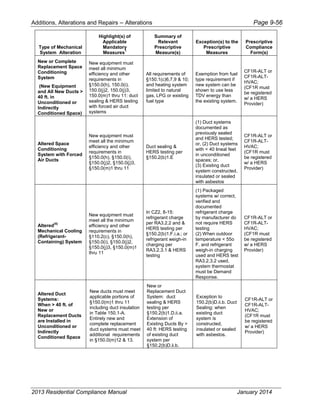
Download to read offline


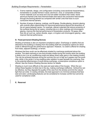
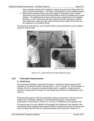
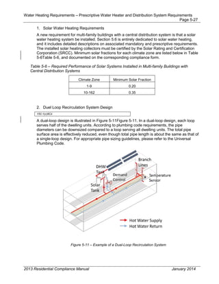
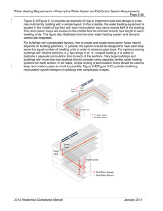
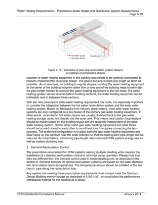
![Introduction – Mandatory Measures and Compliance Approaches Page 1-9
2013 Residential Compliance Manual January 2014
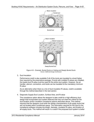
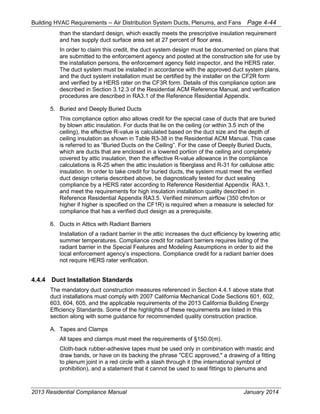
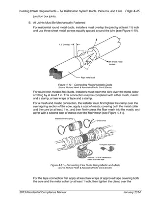
All residential buildings not in the above low-rise category are covered in the 2013 edition
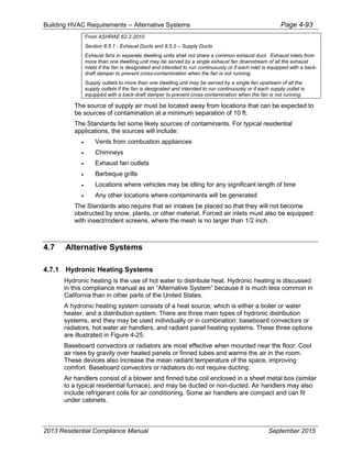
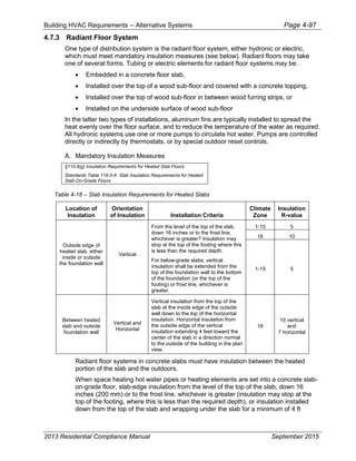
of the Energy Commission's Nonresidential Compliance Manual (see Parts 1.1 and 1.2).
A. A single-family building is a single dwelling unit of occupancy group R-3, as defined
in the CBC, which stands separate and unattached from other dwelling units but may
have an attached garage.
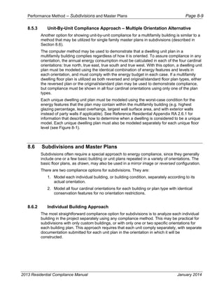
B. A multi-family building is a dwelling unit of occupancy group R, as defined in the
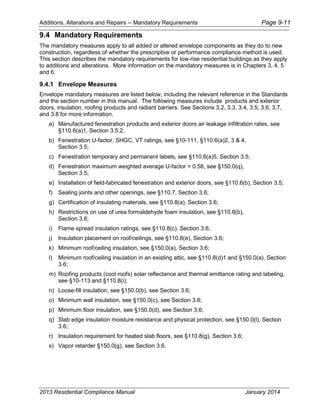
CBC; that shares a common wall and/or floor/ceiling with at least one other dwelling
unit. See Chapter 8 for more information on multi-family energy compliance. A single
family attached building is a dwelling unit of occupancy group R that shares a common
wall with another dwelling unit.
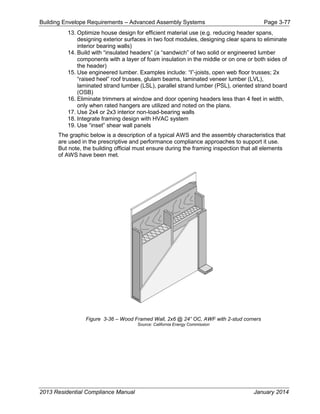
C. An addition to an existing building increases both the conditioned floor area and
volume of a building, which can be new construction or adding space conditioning to
an existing unconditioned space. See Chapter 9 for more information on energy
compliance of additions.
D. An existing building is: "...a building erected prior to the adoption of [the current]
code, or one for which a legal building permit has been issued." [CBC, Part 2]
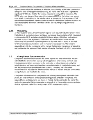
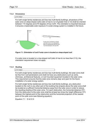
1.5.3 Building Orientation
Building orientation can affect the energy use of a building, particularly in cooling
dominated climate zones with high amount of west facing glass. Some prescriptive
requirements and performance modeling inputs for compliance with the Standards require
a description of the building orientation.
A. East-Facing
"East-facing is oriented to within 45 degrees of true east, including 45°0'0" south of
east (SE), but excluding 45°0'0" north of east (NE)." [§100.1]
B. North-Facing
"North-facing is oriented to within 45 degrees of true north, including 45°0'0" east of
north (NE), but excluding 45°0'0" west of north (NW)." [§100.1]
C. South-Facing
"South-facing is oriented to within 45 degrees of true south, including 45°0'0" west of
south (SW), but excluding 45°0'0" east of south (SE)." [§100.1]
D. West-Facing
"West-facing is oriented to within 45 degrees of true west, including 45°0'0" due north
of west (NW) but excluding 45°0'0" south of west (SW)." [§100.1]](https://image.slidesharecdn.com/cec-400-2013-001-cmf-rev2-151019231936-lva1-app6891/85/Cec-400-2013-001-cmf-rev2-pdf-18-320.jpg)
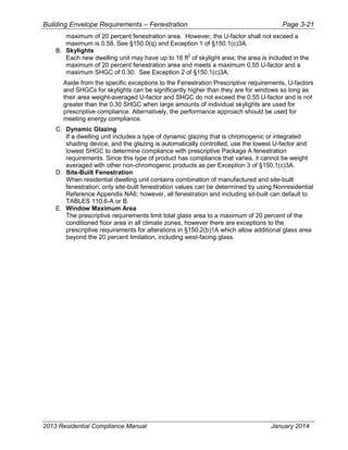
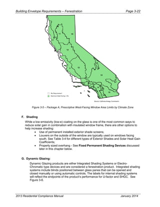
![Introduction – Climate Zones Page 1-21
2013 Residential Compliance Manual January 2014
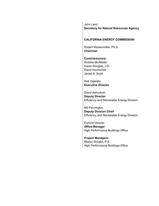
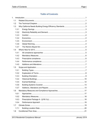
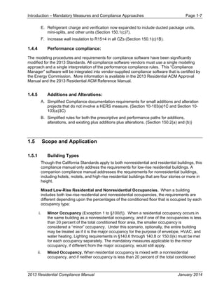
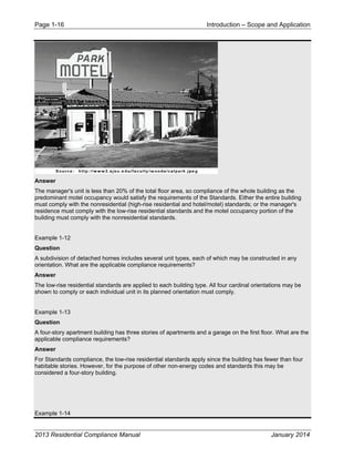
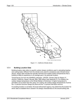
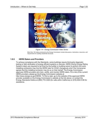
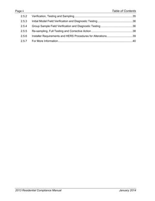
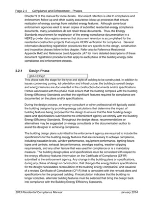
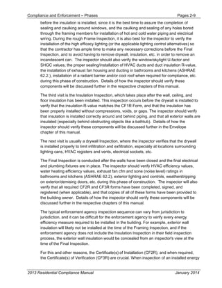
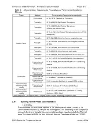
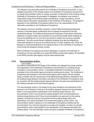
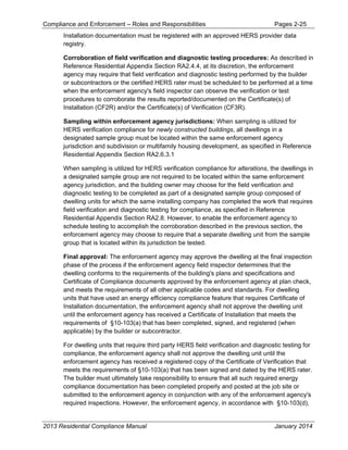
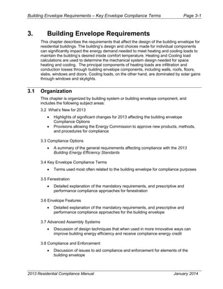
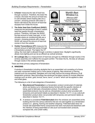
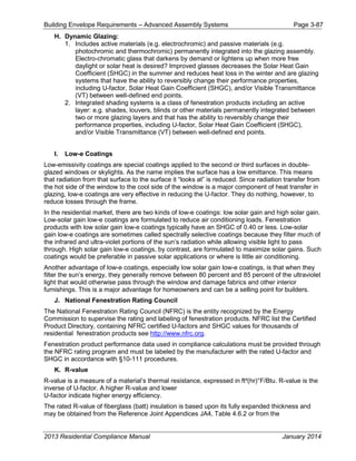
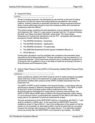
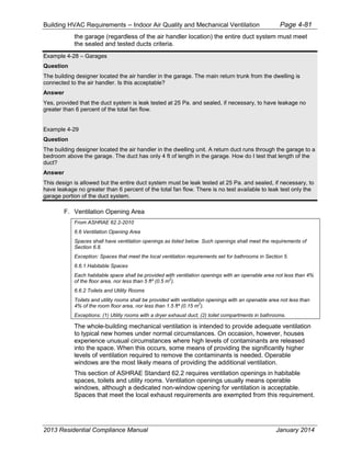
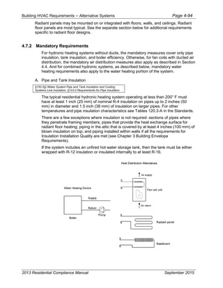
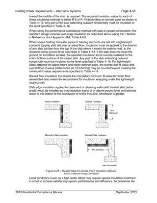
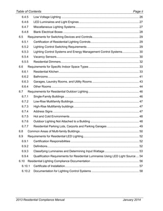
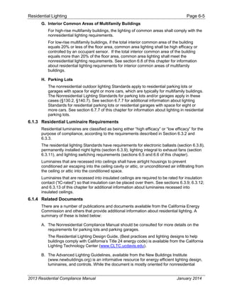
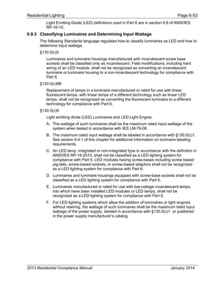
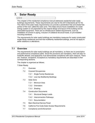
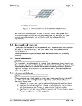
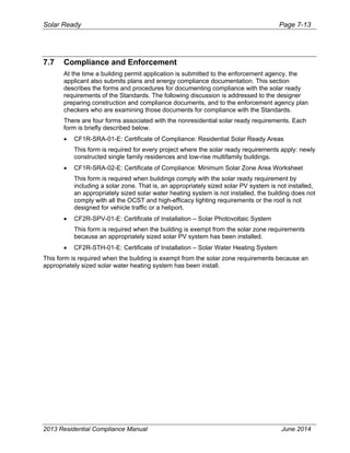
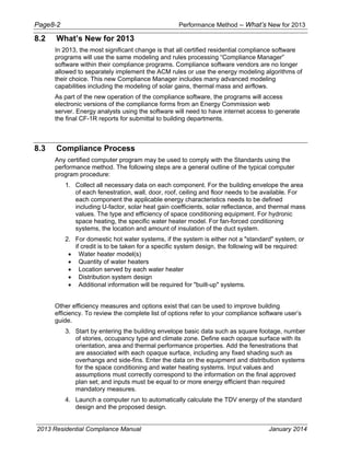
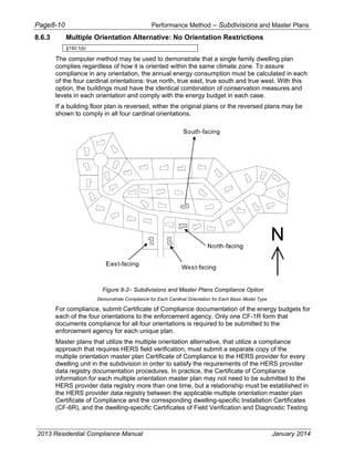
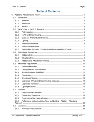
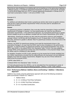
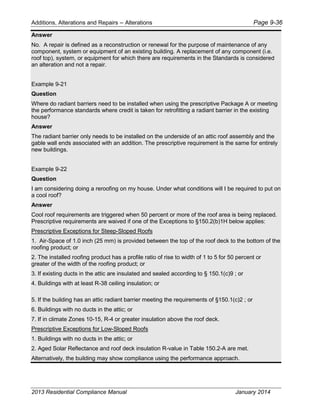
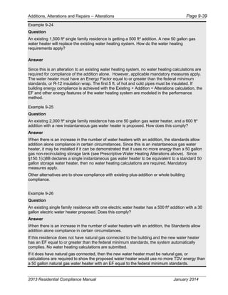
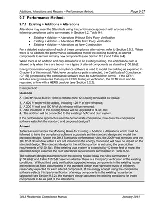
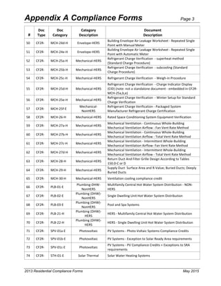
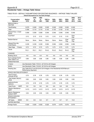
1.8 Conditioned Floor Area
Conditioned floor area (CFA) is the total floor area (in square feet) of enclosed conditioned
space on all floors of a building, as measured at the floor level of the exterior surfaces of
exterior walls enclosing the conditioned space. [§100.1] This term is also referred to in the
Standards simply as the floor area.
This is an important value for the purpose of compliance since annual energy use is divided
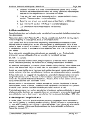
by this value to obtain the energy budget. In the prescriptive package, the maximum
fenestration and west facing fenestration area requirements are expressed as a percentage
of this value.
CFA is calculated from the plan dimensions of the building, including the floor area of all
conditioned and indirectly conditioned space on all floors. It includes lofts and mezzanines but
does not include covered walkways, open roofed-over areas, porches, pipe trenches, exterior
terraces or steps, chimneys, roof overhangs, or parking garages. Unheated basements or
closets for central gas forced air furnaces are also not included, unless shown to be indirectly
conditioned.
The floor area of an interior stairway is determined as the CFA beneath the stairs and the
tread area of the stairs themselves.
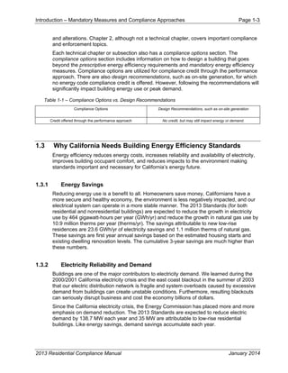
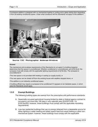
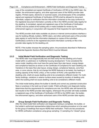
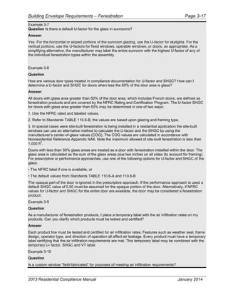
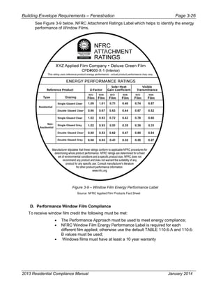
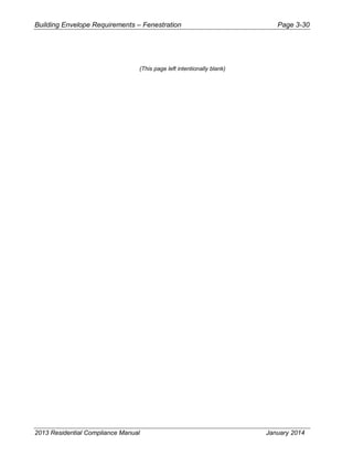
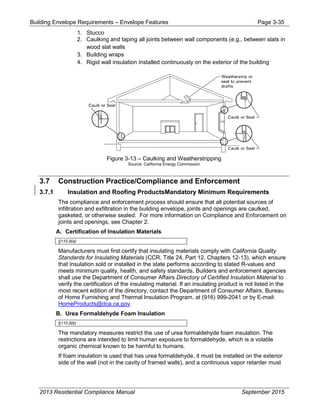
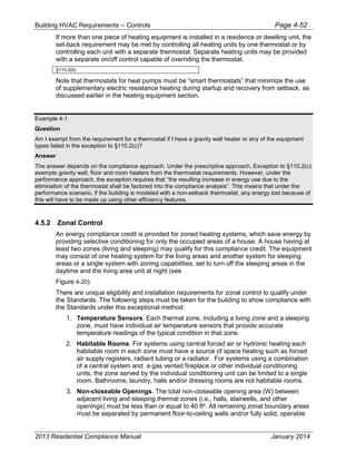
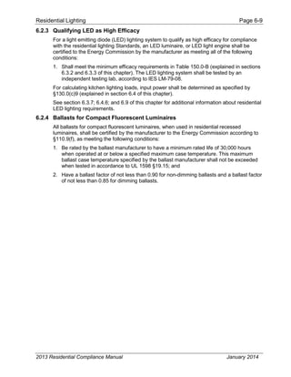
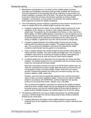
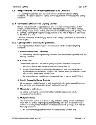
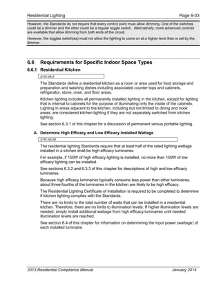
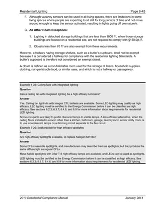
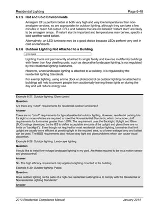
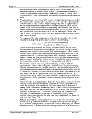
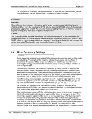
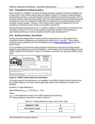
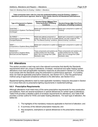
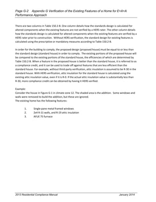
See Figure 1-2 for an example of how CFA is calculated.
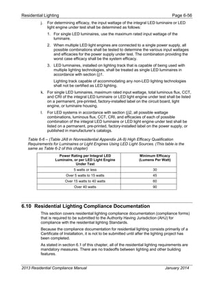
Second Floor
First Floor
Area 2 (conditioned Space Outlined)
Area 1 (Conditioned Space
Outlined)
Note: Measure from
exterior surfaces of
exterior partions
Unheated Garage
Note: Do not count
unconditioned
space
Total conditioned floor area = Area 1 + Area 2
NOTE: Stair area
should be included in
both the 1st and 2nd
floor areas
Figure 1-2 – Total Conditioned Floor Area](https://image.slidesharecdn.com/cec-400-2013-001-cmf-rev2-151019231936-lva1-app6891/85/Cec-400-2013-001-cmf-rev2-pdf-30-320.jpg)
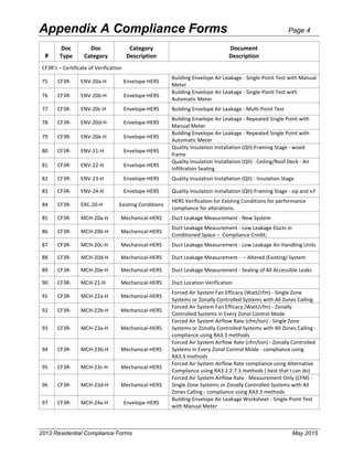
![Building Envelope Requirements – Fenestration Page 3-18
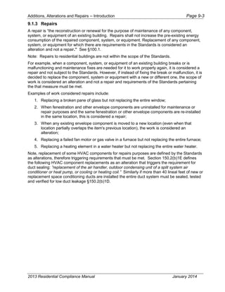
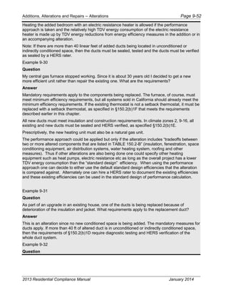
Answer
No. Most custom windows are manufactured and delivered to the site either completely assembled or
“knocked down,” which means they are a manufactured product. A window is considered field-fabricated
when the windows are assembled at the building site from the various elements that are not sold together
as a fenestration product (i.e., glazing, framing and weatherstripping). Field-fabricated does not include site-
assembled frame components that were manufactured elsewhere with the intention of being assembled on
site (such as knocked down products, sunspace kits, and curtain walls).
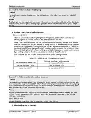
Example 3-11
Question
What constitutes a “double-pane” window?
Answer
Double-pane (or dual-pane) glazing is made of two panes of glass (or other glazing material) separated by
space (generally 1/4" [6 mm] to 3/4" [18 mm]) filled with air or other gas. Two panes of glazing laminated
together do not constitute double-pane glazing.
Example 3-12
Question
To get daylight into a room in my new house, I plan on installing a tubular skylight and will be using the
performance approach for compliance purposes. The skylight has a clear plastic dome exterior to the roof,
a single pane ¼-inch (6 mm)-thick acrylic diffuser mounted at the ceiling, and a metal tube connecting the
two. How do I determine the U-factor and SHGC that I will need to determine if I can comply with the
Standards, if Uc is 1.20 and SHGCc is 0.85?
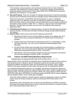
Answer
Tubular daylighting device (TDD) skylights are an effective means for bringing natural light into interior
spaces, as are traditional skylights.
There are three methods available for determining the thermal efficiencies for TDDs:
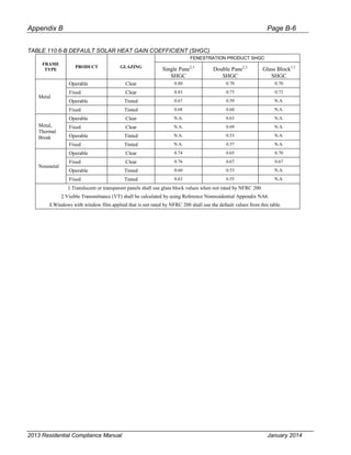
The first is to use the default U-factor from Standards TABLE 110.6-A. This tubular skylight would be
considered a metal frame, fixed, single-pane skylight resulting in a U-factor of 1.19, which must appear on a
label preceded by the words “CEC Default U-factor.” (A tubular daylighting device skylight would have to
have two panes of glazing with an air space of less than 2 inches (50 mm) between them at the plane of the
ceiling insulation for it to be considered double-pane.);
The second method is to determine the U-factor from the Reference Nonresidential Appendix NA6,
Equation NA6-1. The U-factor for this tubular daylighting device skylight would be based on metal with no
curb (Table NA6-5). The U-factor for this skylight, using Equation NA6-1, is 1.25, where Ut = (0.195 +
(0.882 x 1.20)). This must appear on a label stated as “CEC Default U-factor 1.25.”
2013 Residential Compliance Manual January 2014](https://image.slidesharecdn.com/cec-400-2013-001-cmf-rev2-151019231936-lva1-app6891/85/Cec-400-2013-001-cmf-rev2-pdf-99-320.jpg)

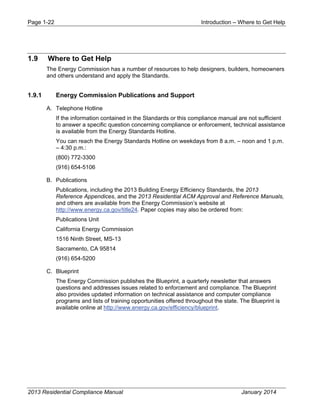
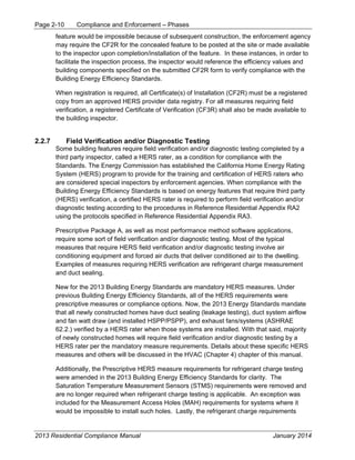
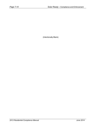
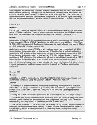
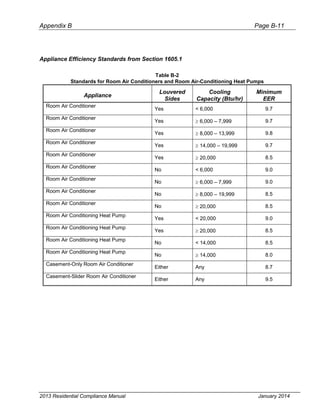
![Building Envelope Requirements – Envelope Features Page 3-38
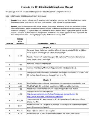
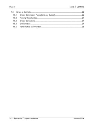
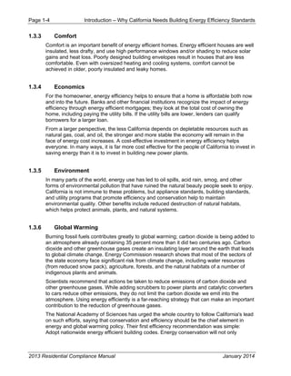
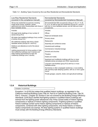
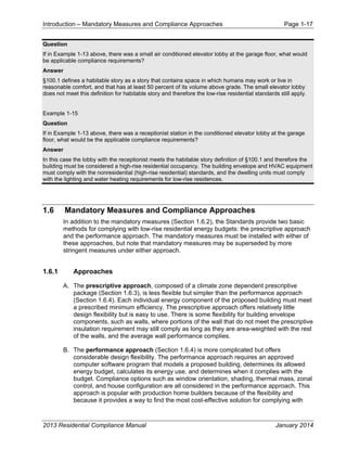
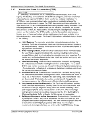
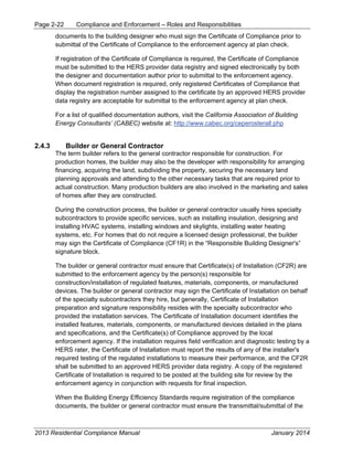
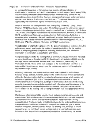
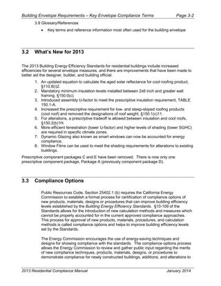
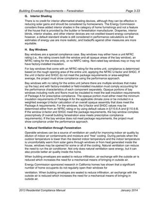
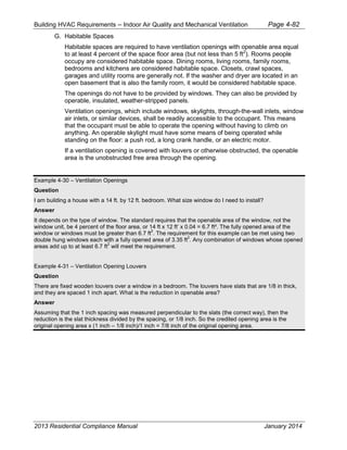
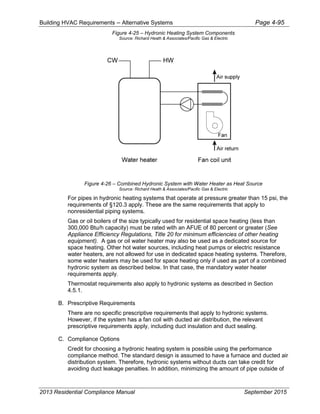
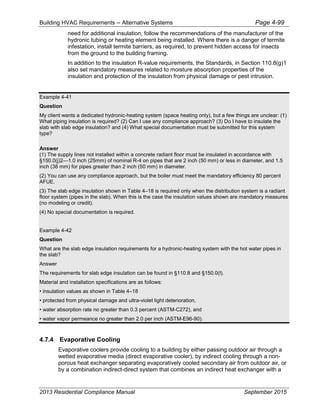
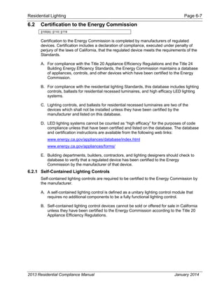
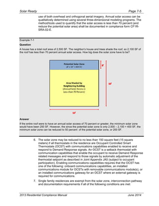
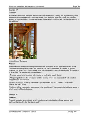
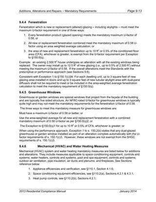
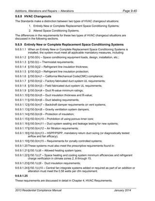
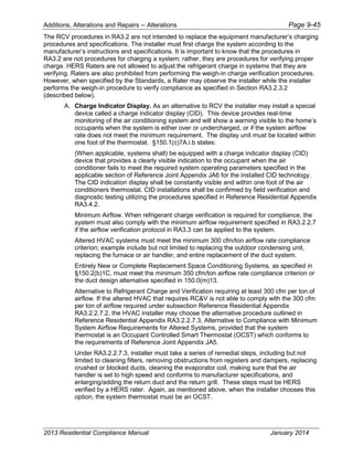
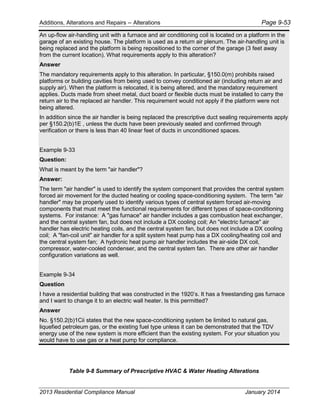
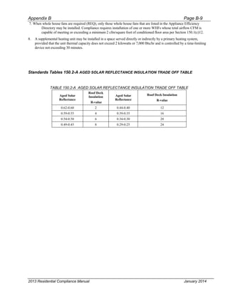
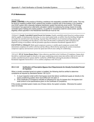
2. 3-year aged solar reflectance
All requirements of the Standards are based on the 3-year aged reflectance. However, if
the aged value for the reflectance is not available in the CRRC’s Rated Product Directory,
then the aged value shall be derived from the CRRC initial value. The equation below can
be used to calculated the aged rated solar reflectance until the appropriate aged rated
value for the reflectance is posted in the directory.
Equation 3-2: Aged Reflectancecalculated=(0.2+ β[ρinitial – 0.2])
Where:
ρinitial = Initial Reflectance listed in the CRRC Rated Product Directory
β = soiling resistance which is listed in Table 3-6
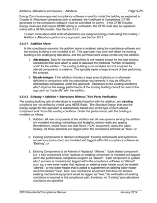
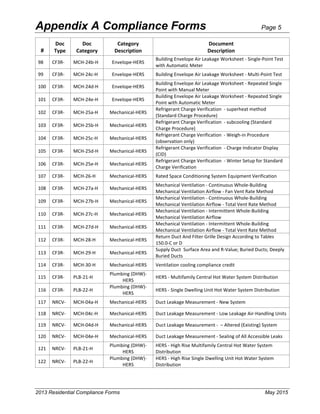
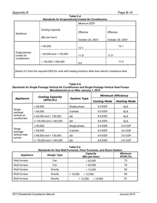
Table 3-6 – Values Of Soiling Resistance β By Product Type
PRODUCT TYPE β
Field-applied coating 0.65
Other 0.70
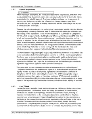
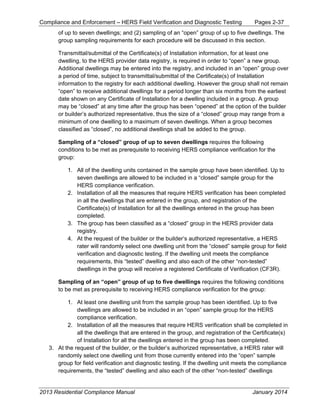
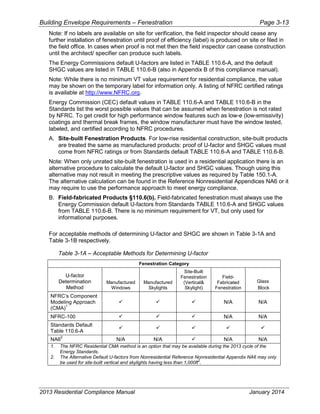
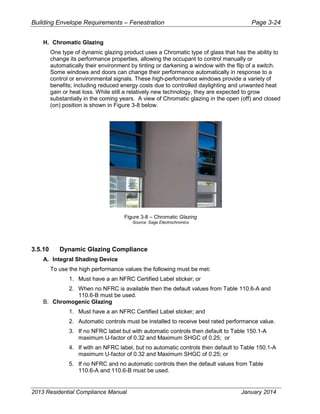
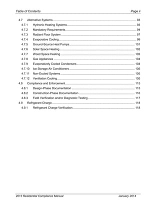
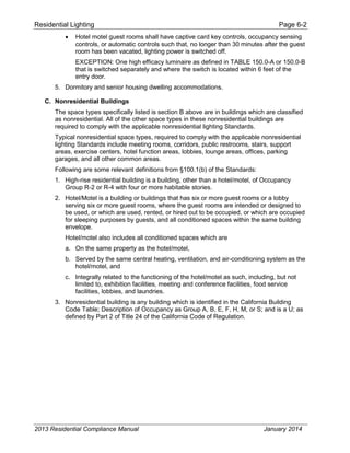
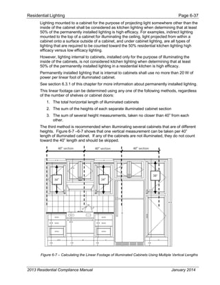
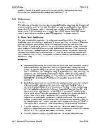
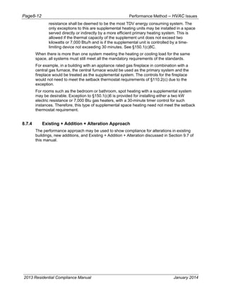
The Standards do not distinguish between initial and aged thermal emittance, meaning
that either value can be used to demonstrate compliance with the Standards. If a
manufacturer fails to obtain CRRC certificate for their roofing products, the following
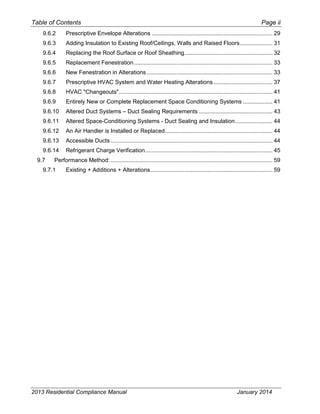
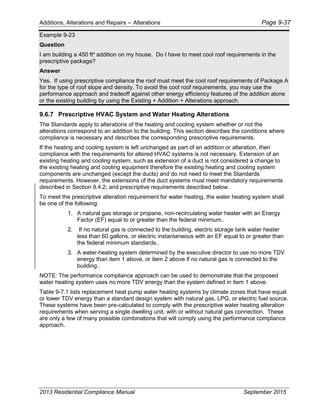
default aged solar reflectance and thermal emittance values must be used for compliance:
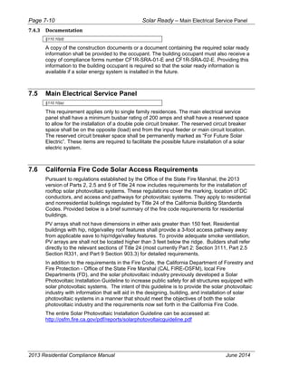
1. For asphalt shingles, 0.08/0.75
2. For all other roofing products, 0.10/0.75
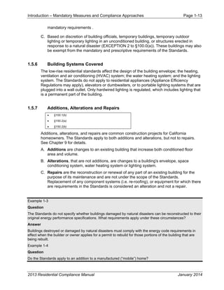
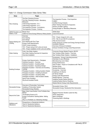
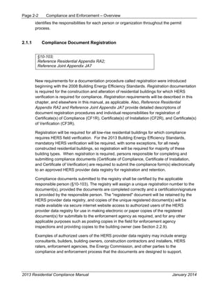
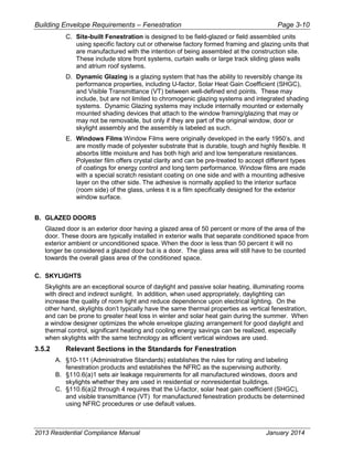
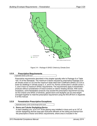
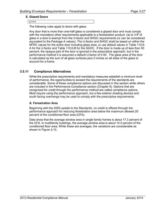
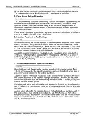
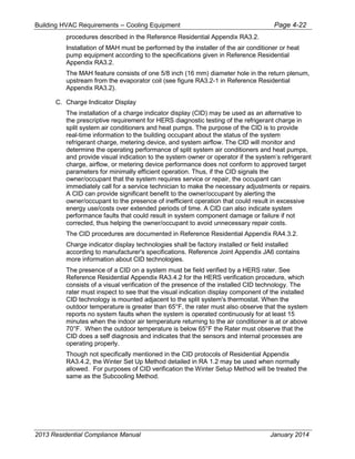
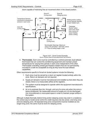
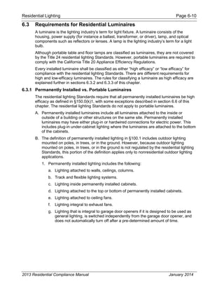
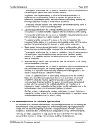
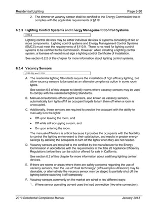
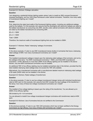
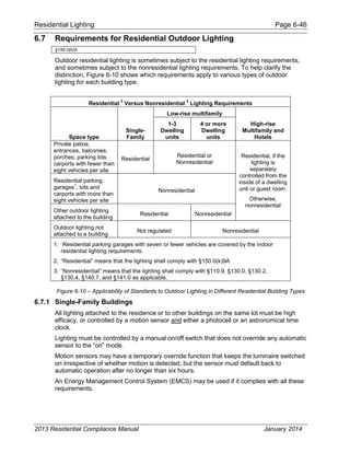
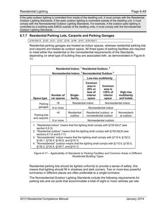
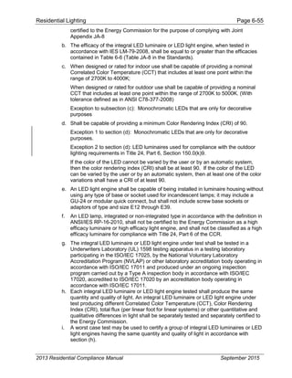
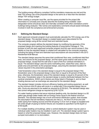
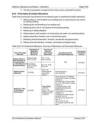
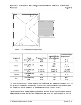
Figure 3-15 – Sample CRRC Product label and information
Source: Cool Roof Rating Council
3.8 Field Applied Liquid Coatings
3.8.1 Field Applied Liquid Coatings
There are a number of liquid products, including elastomeric coatings and white acrylic
coatings that qualify for Field Applied Liquid Coatings. The Standards specify minimum
performance and durability requirements for field-applied liquid coatings. Please note that
these requirements do not apply to industrial coatings that are factory-applied, such as
2013 Residential Compliance Manual January 2014](https://image.slidesharecdn.com/cec-400-2013-001-cmf-rev2-151019231936-lva1-app6891/85/Cec-400-2013-001-cmf-rev2-pdf-119-320.jpg)

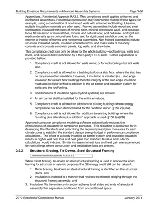
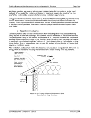
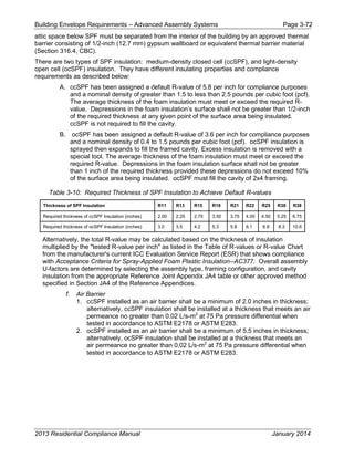
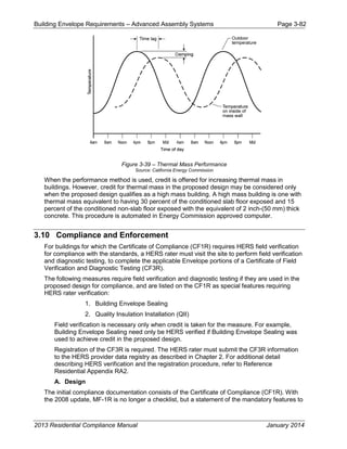
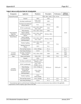
![Building Envelope Requirements – Advanced Assembly Systems Page 3-74
for mass walls using values from Reference Appendices. In prescriptive compliance,
the walls will qualify as either light mass or heavy mass walls depending on the
thickness – remember a heat capacity (HC) of 8.0 Btu/°F-ft² is equivalent to a heavy
mass wall (40 lb/ft³). The prescriptive requirements for heavy mass walls are less
stringent than the criteria for wood-framed walls. Reduced insulation is allowed
because the effects of the thermal mass (interior and exterior) can compensate for less
insulation.
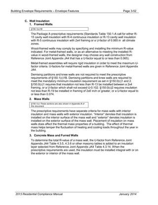
The thermal performance of log walls is shown in Reference Joint Appendix JA4, Table
4.3.11. The U-factor ranges from 0.133 for a 6-inch wall to 0.053 for a 16-inch wall. The U-
factor of an 8-inch wall is 0.102, which complies with the R-13 prescriptive requirements.
U-factors for other log wall constructions (not shown in Reference Joint Appendix JA4)
would have to be approved by the Energy Commission through the exceptional methods
process.
Log walls have a heat capacity that is in excess of conventional construction. Reference
Joint Appendix JA4 [Table 4.3.11 Thermal Properties of Log Home Walls] shows that a 6-
inch wall has an HC of 4.04 which increases to 10.77 for a 16-inch wall. The thermal mass
effects of log home construction can be accounted for within the performance approach.
Air infiltration between log walls can be considerably different among manufacturers
depending upon the construction technique used. For purposes of compliance, infiltration
is always assumed to be equivalent to a wood-frame building. However, the builder should
consider using a blower door test to find and seal leaks through the exterior walls.
i. Straw Bale
Straw bale construction is regulated within the CBC and specific guidelines are
established for moisture content, bale density, seismic bracing, weather protection, and
other structural requirements.
The Energy Commission has determined specific thermal properties for straw bale walls
and thermal mass benefits associated with this type of construction. The performance
compliance approach can be used to model the heat capacity characteristics of straw
bales.
Straw bales that are 23 inch by 16 inch are assumed to have a thermal resistance of R-30,
whether stacked so the walls are 23 inch wide or 16 inch wide. The minimum density of
load bearing walls is 7.0 lb/ft3, and this value or the actual density may be used for
modeling straw bale walls in the performance approach. Specific heat is set to 0.32 Btu/lb-
°F. Volumetric heat capacity (used in some computer programs) is calculated as density
times specific heat. At a density of 7 lb/ft³, for example, the volumetric heat capacity is
2.24 Btu/ft³-°F.
The minimum dimension of the straw bales when placed in the walls must be 22 inch by
16 inch and there are no restrictions on how the bales are stacked. Due to the higher
resistance to heat flow across the grain of the straw, a bale laid on edge with a nominal
16-inch horizontal thickness has the same R-Value (R-30) as a bale laid flat.
j. Structural Insulated Panels (SIPS)
Structural Insulated Panels (SIPS) are a non-framed advanced construction system that
consists of rigid insulation (usually expanded polystyrene) sandwiched between two
sheets of OSB or plywood. Little or no structural framing penetrates the insulation layer.
Panels are typically manufactured at a factory and shipped to the job site in assemblies
that can be as large as 8 ft by 24 ft.
2013 Residential Compliance Manual January 2014](https://image.slidesharecdn.com/cec-400-2013-001-cmf-rev2-151019231936-lva1-app6891/85/Cec-400-2013-001-cmf-rev2-pdf-155-320.jpg)
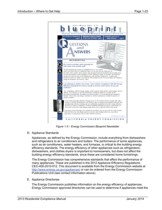
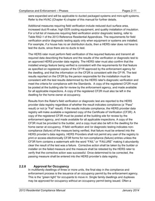
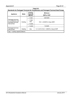
![Building Envelope Requirements – Advanced Assembly Systems Page 3-78
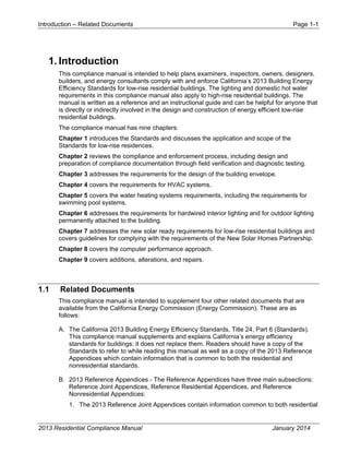
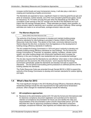
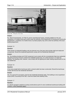
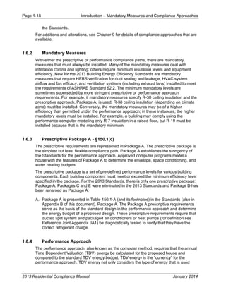
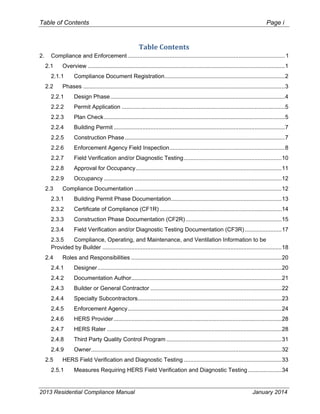
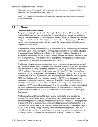
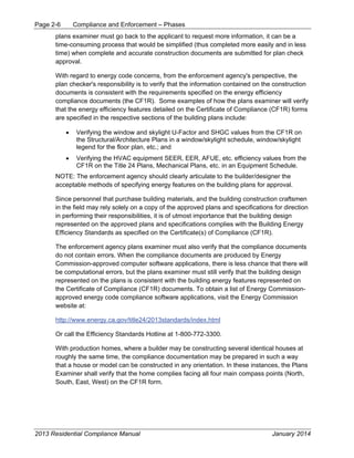
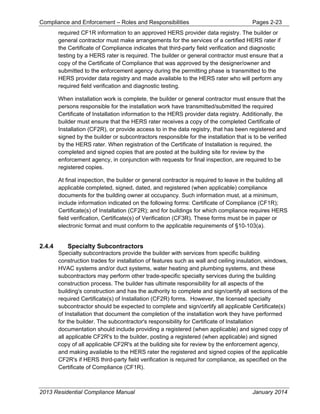
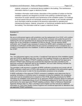
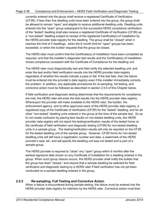
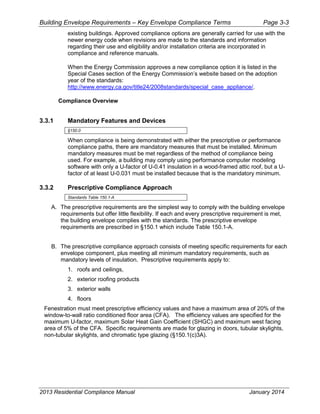
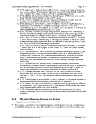
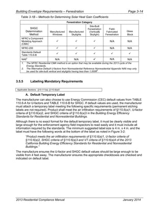
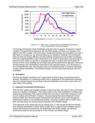
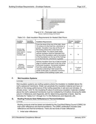
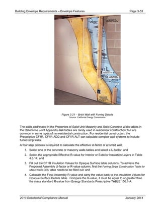
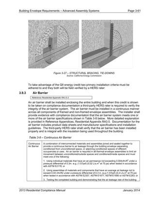
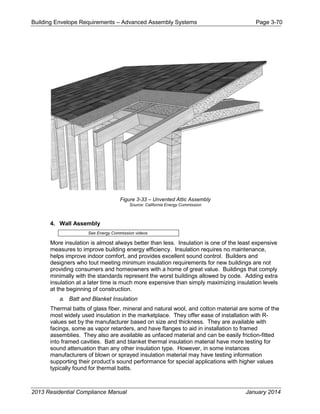
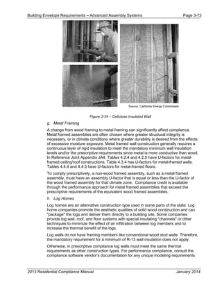
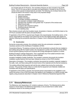
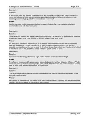
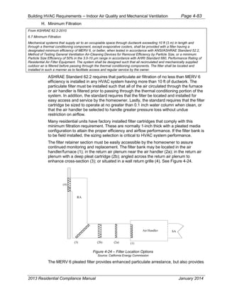
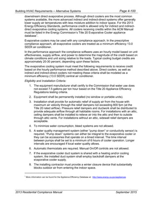
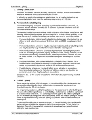
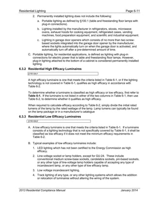
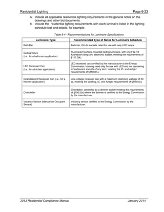
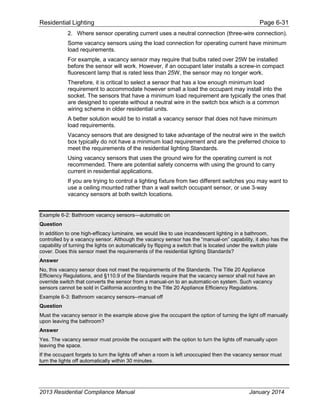
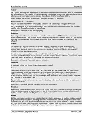
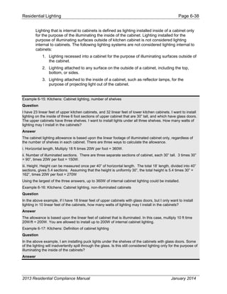
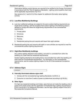
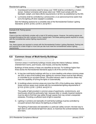
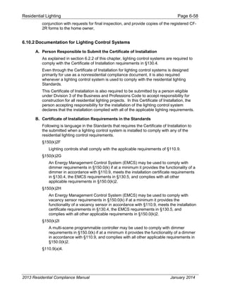
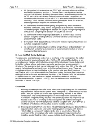
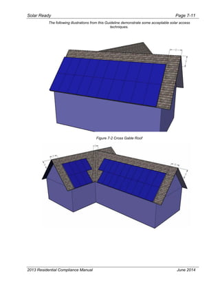
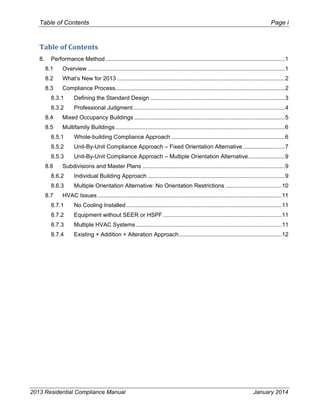
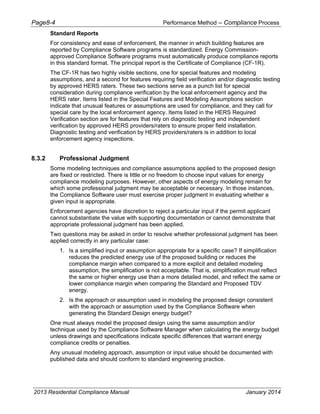
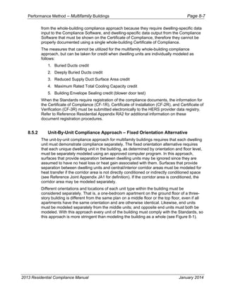
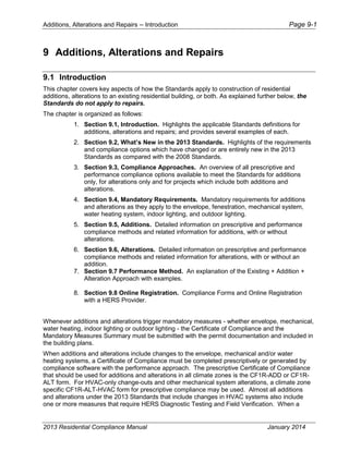
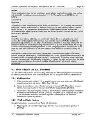
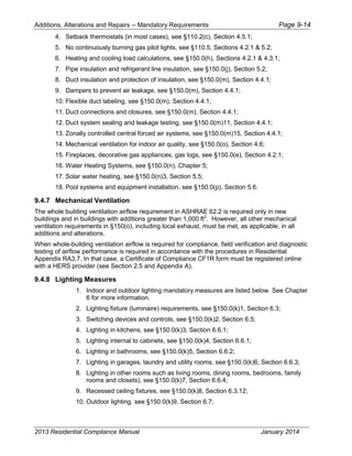
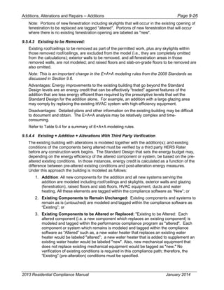
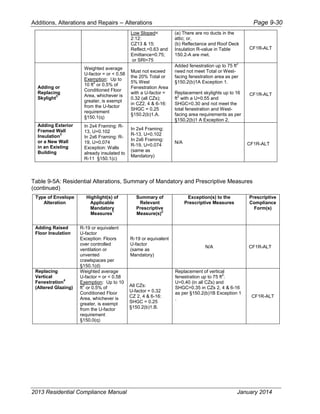
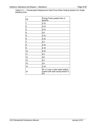
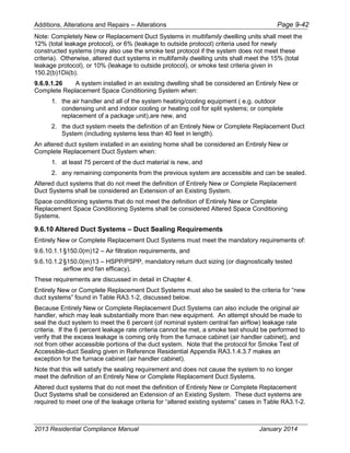
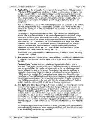
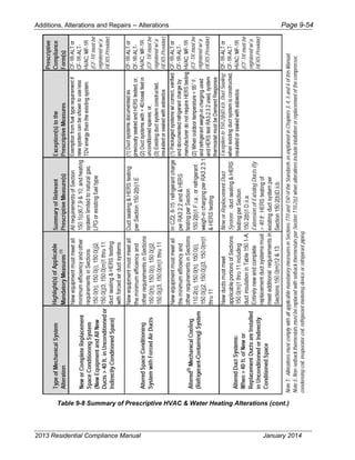
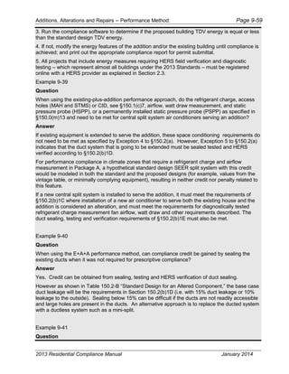
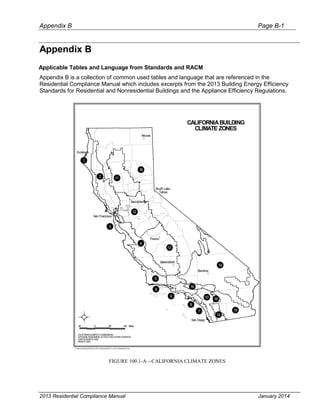
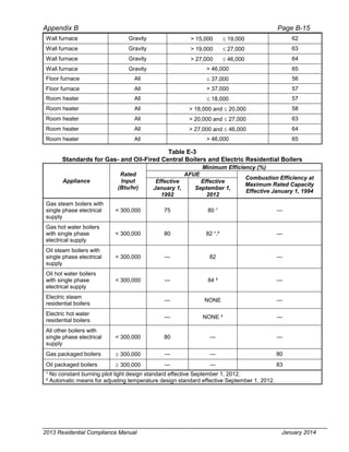
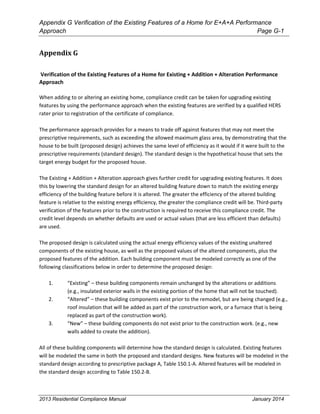
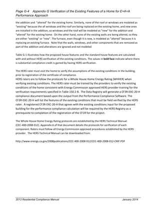
Table 3-11 – Assumptions
Layer Assembly Type: Wall 2x6 @ 24” OC AWS R-Value
Framing Material: Wood Framing Factor 17
Assembly Components Cavity (Rc) Frame (Rf)
1 Outside air film 0.17 0.17
2 7/8 inch 3-coat stucco 0.18 0.18
3 3/8 inch sheathing 0.47 0.47
4 R-21 insulation 21.0 --
5 2x6 douglass fir framing @ R-1.086/inch -- 5.973
6 ½ inch gypboard 0.45 0.45
7 Inside air film 0.68 0.68
Subtotal 23.01 7.983
[1/Rc x (1-Frame% / 100)] + [(1/Rf)] x (Frame% / 100)] =
Assembly U-factor
Assembly
U-factor
0.057
Assumptions: Values in Table 3-11 were calculated using the parallel heat flow calculation
method, documented in the 2009 ASHRAE Handbook of Fundamentals. The construction
assembly assumes an exterior air film of R-0.17, a 7/8 inch layer of stucco of R-0.18 (SC01),
building paper of R-0.06 (BP01), sheathing or continuous insulation layer if present, the cavity
insulation / framing layer, ½ inch gypsum board of R-0.45 (GP01), and an interior air film 0.68.
The framing factor is assumed to be 25 percent for 16 inch stud spacing, 22 percent for 24 inch
spacing, and 17 percent for Advanced Wall System (AWS).
Actual cavity depth is 3.5 inch for 2x4, 5.5 inch for 2x6. The thickness of the stucco is assumed to
be reduced to 3/8 inch (R-0.08) when continuous insulation is applied.
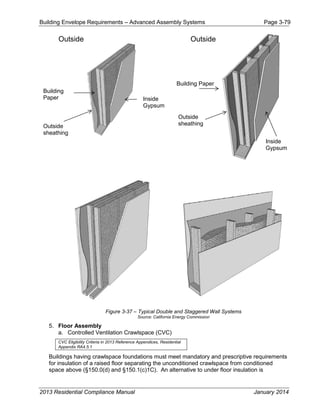
m. Double and Staggered Wall Assemblies
Double wall and staggered wall systems were developed to better accommodate electrical and
plumbing systems, allow higher levels of insulation, and provide greater sound attenuation. The
advantages of these types of wall systems are that:
1. Smaller dimensional lumber can be used
2. Easier to install installation properly
3. Eliminates thermal bridging through the framing
4. Reduces sound transmission through the wall
With double walls, insulation may be on one side of the wall or on both (higher R-values). It is not
uncommon to find double walls with insulation installed within the outside wall cavities, leaving the
inside wall sections open for wiring and plumbing purposes.
With staggered walls, thermal batt insulation may be installed horizontally or vertically, butting the
sides of the insulation until the cavity across the entire wall section is completely filled.
2013 Residential Compliance Manual January 2014](https://image.slidesharecdn.com/cec-400-2013-001-cmf-rev2-151019231936-lva1-app6891/85/Cec-400-2013-001-cmf-rev2-pdf-159-320.jpg)
![Building Envelope Requirements – Advanced Assembly Systems Page 3-88
manufacturer’s literature. When the insulation is compressed, the R-value is reduced. The most
common insulation compression occurs with R-19 and R-22 insulation batts installed in locations
with a nominal 6-inch framing that is actually only 5.5 in. thick. To achieve its rated insulation
value, an R-19 batt of insulation expands to a thickness of six and one quarter inches. If it is
compressed into 2x6 framing with an actual depth of 5.5 inches, the insulation R-Value is lowered
to 17.8.
L. Solar Heat Gain Coefficient
Solar heat gain coefficient (SHGC) is a measure of the relative amount of heat gain from sunlight
that passes through a fenestration product. SHGC is a number between zero and one that
represents the ratio of solar heat that passes through the fenestration product to the total solar
heat that is incident on the outside of the window. A low SHGC number (closer to 0) means that
the fenestration product keeps out most solar heat. A higher SHGC number (closer to 1) means
that the fenestration product lets in most of the solar heat.
SHGCc is the SHGC for the center of glazing area; SHGC or SHGCt is the SHGC for the total
fenestration product and is the value used for compliance with the Standards.
M. U-factor of Fenestration Products
U-factor is a measure of how much heat passes through a construction assembly or a
fenestration product. The lower the U-factor, the more energy efficient the product is. The units for
U-factor are Btu of heat loss each hour per ft² of window area per degree °F of temperature
difference (Btu/hr-ft²-°F). U-factor is the inverse of R-value.
The U-factor considers the entire product, including losses through the center of glass, at the
edge of glass where a metal spacer typically separates the double-glazing panes, losses through
the frame and through the mullions. For metal-framed windows, the frame losses can be
significant.
U-factor is the U-factor for the center of glazing area; U-factor is the U-factor for the total
fenestration product and is the value used for compliance with the Building Energy Efficiency
Standards.
Estimating the rate of heat transfer through a fenestration product is complicated by the variety of
frame configurations for operable windows, the different combinations of materials used for
sashes and frames, and the difference in sizes available in various applications. The NFRC rating
system makes the differences uniform, so that an entire fenestration product line is assumed to
have only one typical size. The NFRC rated U-factor may be obtained from a directory of certified
fenestration products, directly from a manufacturer's listing in product literature, or from the
product label.
N. Building Orientation
Orientation of the building, particularly walls and fenestration, can impact its energy use.
Orientation is also critical for sizing and installing renewable energy sources, such as solar
thermal collectors for domestic water heating and solar electric collectors to help offset electrical
demand.
East-Facing- "East-facing is oriented to within 45 degrees of true east, including 45°0'0" south of
east (SE), but excluding 45°0'0" north of east (NE)." [§100.1] The designation “East-Facing” is
also used in production buildings using orientation restrictions (e.g., Shaded Areas: East-Facing).
North-Facing- "North-facing is oriented to within 45 degrees of true north, including 45°0'0" east
of north (NE), but excluding 45°0'0" west of north (NW)." [§100.1]
South-Facing- “South-facing is oriented to within 45 degrees of true south, including 45°0’0”
west of south (SW), but excluding 45°0’0” east of south (SE).” [§100.1] The designation “South-
2013 Residential Compliance Manual January 2014](https://image.slidesharecdn.com/cec-400-2013-001-cmf-rev2-151019231936-lva1-app6891/85/Cec-400-2013-001-cmf-rev2-pdf-169-320.jpg)
![Building Envelope Requirements – Advanced Assembly Systems Page 3-89
Facing” is also used in production buildings using orientation restrictions (e.g., Shaded Areas:
East-Facing).
West-Facing- "West-facing is oriented to within 45 degrees of true west, including 45°0'0" due
north of west (NW) but excluding 45°0'0" south of west (SW)." [§100.1]. The designation “West-
Facing” is also used in production buildings using orientation restrictions (e.g., Shaded Areas:
West-Facing).
2013 Residential Compliance Manual January 2014](https://image.slidesharecdn.com/cec-400-2013-001-cmf-rev2-151019231936-lva1-app6891/85/Cec-400-2013-001-cmf-rev2-pdf-170-320.jpg)
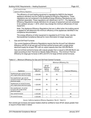
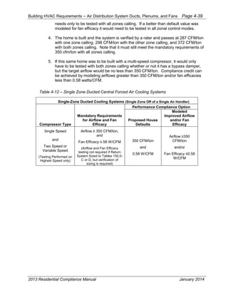
![Building HVAC Requirements – Overview Page 4-2
4.1.2 What’s New for the 2013 Standards
The following is a summary of the new HVAC measures for the 2013 Standards, including
new compliance options that provide greater flexibility in complying with the Standards
when using the performance method. See individual sections of this Manual for more
detail.
Mandatory Features and Devices - Section 150.0
1. The indoor design temperature for heating load calculations has been changed
from 70 degrees to 68 degrees. [150.0(h)2]
2. Air conditioning condensers are required to be located at least 5 feet from a
clothes dryer vent outlet. [150.0(h)3]
3. Gas furnaces must be designed and installed to meet the manufacturer’s
maximum temperature split in heating mode. [150.0(h)4]
4. There are some changes to the tables specifying mandatory minimum insulation
on air conditioning refrigerant lines. [150.0(j)2C]
5. There are some changes to the mandatory insulation protection for insulated pipes
found outside conditioned space. [150.0(j)3B]
6. There is a new reference to a mandatory duct construction standard,
ANSI/SMACNA-006-2006 HVAC Duct Construction Standard. [150.0(m)1]
7. The mandatory minimum duct insulation R-value has been raised from R-4.2 to R-
6, except for ducts located completely within directly conditioned space.
[150.0(m)1]
8. Duct sealing and field verification is now a mandatory measure (moved from the
prescriptive packages) and can no longer be traded off by using the performance
approach. [150.0(m)11]
9. There are some changes to the target leakage rates for dwellings in multi-family
buildings. [150.0(m)11]
10. There are new mandatory requirements for filtration of all air passing through a
ducted space conditioning system. The requirements affect the design, efficiency,
pressure drop and labeling of the filtration devices. [150.0(m)12]
11. There are new mandatory requirements to ensure proper duct and filter grill sizing
for forced air distribution systems that supply cooling to an occupiable space.
They include requirements for a hole for a static pressure probe (HSPP) and an
option to either size return ducts based on prescriptive tables or field testing to
meet airflow and fan watt requirements. [150.0(m)13]
12. There are some new mandatory requirements for space cooling systems that
utilize automatic zonal control to meet airflow and fan watt draw requirements.
[150.0(m)15]
13. The mandatory whole building ventilation requirement of ASHRAE 62.2 is now a
HERS verified measure. [150.0(o)]
2013 Residential Compliance Manual January 2014](https://image.slidesharecdn.com/cec-400-2013-001-cmf-rev2-151019231936-lva1-app6891/85/Cec-400-2013-001-cmf-rev2-pdf-174-320.jpg)
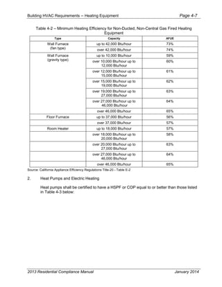
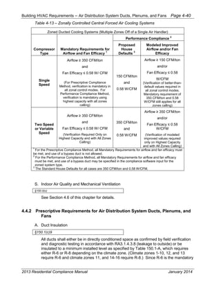
![Building HVAC Requirements – Overview Page 4-3
Prescriptive and Performance Compliance Approaches - Section150.1
1. When higher than minimum SEER ratings are specified using the performance
approach, installation of proper equipment is now a HERS verified measure.
Previously this only applied to high EER equipment. [150.1(b)4Bi]
2. There is now only one set of prescriptive measures (prescriptive package A).
[150.1(c)]
3. There is a new allowance for supplemental heating systems. It includes limitations
on size and requirements for timing controls. [150.1(c)6]
4. The temperature split approach to minimum airflow verification for refrigerant
charge verification has been omitted. This reduces the number of required
measurement access holes from two to one. [150.1(c)7Aia]
5. Some package units, mini-splits and variable refrigerant flow systems will be
required to demonstrate proper refrigerant charge using a weigh-in approach and
must be verified by a HERS rater. [150.1(c)7Aii]
6. Ducts not insulated because they are deemed to be in directly conditioned space
must be verified by a HERS rater utilizing the duct leakage to outside procedures.
[150.1(c)9]
7. There is a new prescriptive requirement in climate zones 8 through 14 for whole
house fans designed to provide ventilation cooling. [150.1(c)12]
8. When homes utilizing the prescriptive approach have automatic zonal control, they
are prohibited from using bypass ducts that divert supply air directly back to the
return air stream. Using the performance approach, there is an energy penalty for
systems choosing to utilize bypass ducts for zonal control. [150.1(c)13]
9. Maximum Rated Total Cooling Capacity compliance credit has been deleted.
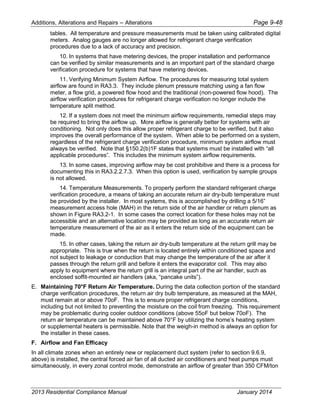
Additions and Alterations - Section 150.2
The new requirements in the 2013 Standards for HVAC systems in homes that are altered
or added to are summarized and discussed in Chapter 9.
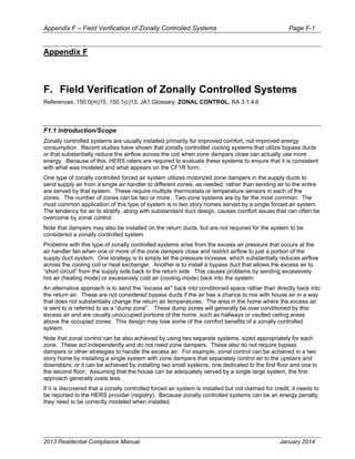
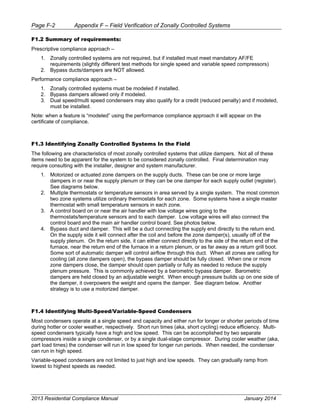
4.1.3 Common System Types
The typical new California home in the central valley and the desert has a gas furnace and
a split system air conditioner. Both heating and cooling is typically distributed to each of
the rooms through air ducts. Most of the mandatory measures and prescriptive
requirements are based on this type of system. In some areas, a heat pump provides
both heating and cooling, eliminating the furnace. In coastal climates and in the
mountains, air conditioning is rare and most new homes are heated by gas furnaces.
Although the Standards focus on the typical system, they also apply to other systems as
well, including some radiant hydronic systems where hot water is distributed to parts of the
home to provide at least some of the heat to conditioned space.
Electric resistance systems are used in some areas and applications, although it is difficult
for them to comply under the Standards.
Ground-source or water source heat pump (geo-exchange) systems are also used,
especially in areas where there is no gas service. Unlike the more typical air source
2013 Residential Compliance Manual January 2014](https://image.slidesharecdn.com/cec-400-2013-001-cmf-rev2-151019231936-lva1-app6891/85/Cec-400-2013-001-cmf-rev2-pdf-175-320.jpg)

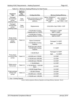

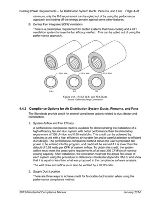
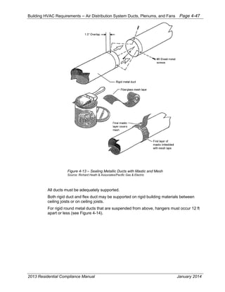
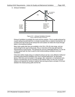
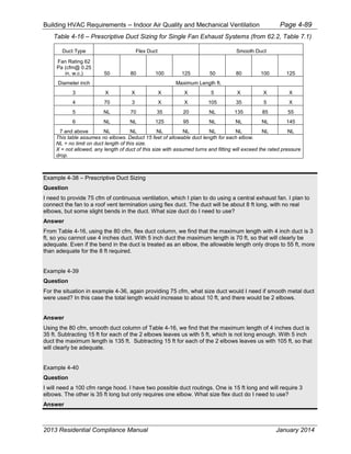
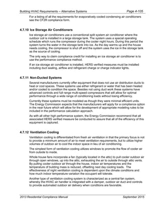
![Building HVAC Requirements – Indoor Air Quality and Mechanical Ventilation Page 4-55
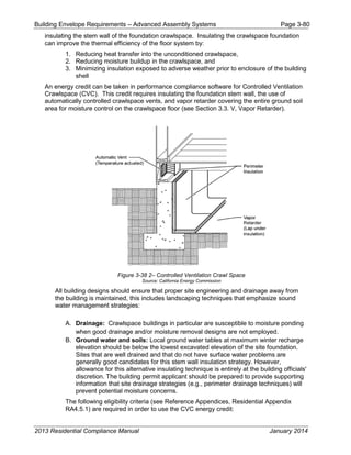
4.6 Indoor Air Quality and Mechanical Ventilation
§150.0(o) and §150.2(a)
As houses have been tightened up over the last twenty years due to energy cost concerns and the use of
large sheet goods and housewrap, what used to be normal infiltration and exfiltration has been significantly
reduced. In the meantime, we have introduced thousands of chemicals into our houses through building
materials, cleaners, finishes, packaging, furniture, carpets, clothing and other products. The California
Standards have always assumed adequate indoor air quality would be provided by a combination of infiltration
and natural ventilation and that home occupants would open windows as necessary to make up any shortfall in
infiltration. However, Commission sponsored research on houses built under the 2001 Standards has revealed
lower than expected overall ventilation rates, higher than expected indoor concentration of chemicals such as
formaldehyde and many occupants who do not open windows regularly for ventilation. The 2013 update
includes mandatory mechanical ventilation intended to improve indoor air quality in homes with low infiltration
and natural ventilation rates.
The Energy Commission adopted the requirements of ASHRAE Standard 62.2-2010,
including ASHRAE Addenda b, c, e, g, h, i, j, l, and n
[http://www.techstreet.com/ashrae/lists/ashrae_standards.html
http://www.techstreet.com/ashrae/products/1866880], except that opening and closing
windows (although permitted by ASHRAE) and continuous operation of central forced air
system air handlers of a central fan integrated ventilation system are not an acceptable
option for providing whole-building ventilation in California.
This section addresses the mandatory requirements for mechanical ventilation. All low-rise
residential buildings are required to have a whole-building ventilation system and satisfy
other requirements to achieve acceptable indoor air quality (IAQ).
The mechanical ventilation and indoor air quality requirements of ASHRAE Standard 62.2
as referenced from Section 150.0(o) are mandatory measures for newly constructed low-
rise residential buildings. The applicable section is §150.0(o) for new construction. The
applicable sections are §150.2(a)1C (prescriptive approach) and §150.2(a)2C
(performance approach) for additions and alterations.
Ventilation for Indoor Air Quality §150.0(o), §150.2(a)1C,
§150.2(a)2C
§150.0(o): Ventilation for Indoor Air Quality. All dwelling units shall meet the
requirements of ASHRAE Standard 62.2 – Ventilation and Acceptable Indoor Air Quality in
Low-Rise Residential Buildings. Window operation is not a permissible method of
providing the Whole-Building Ventilation airflow required in Section 4 of ASHRAE 62.2.
Additionally, all dwelling units shall meet the following requirements:
4.6.1 Field Verification and Diagnostic Testing –
1. Airflow Performance. The Whole-Building Ventilation airflow required by Section
4 of the ASHRAE Standard 62.2 shall be confirmed through field verification and
diagnostic testing in accordance with the applicable procedures specified in
Reference Residential Appendix RA3.7.
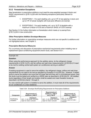
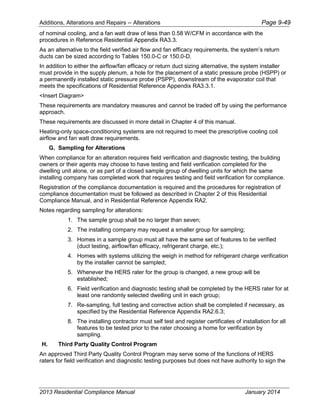
2. §150.2(a)1C and§150.2(a)2C: Additions larger than 1,000 square feet shall meet
the ASHRAE Standard 62.2 Section 4 requirement to provide whole-building
ventilation airflow. The whole building ventilation airflow rate shall be based on
the conditioned floor area for the entire dwelling unit comprised of the existing
dwelling conditioned floor area plus the addition conditioned floor area.
2013 Residential Compliance Manual September 2015](https://image.slidesharecdn.com/cec-400-2013-001-cmf-rev2-151019231936-lva1-app6891/85/Cec-400-2013-001-cmf-rev2-pdf-229-320.jpg)
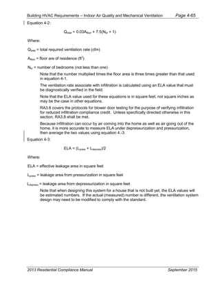
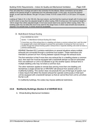
![Building HVAC Requirements – Indoor Air Quality and Mechanical Ventilation Page 4-69
Example 4-11
Question
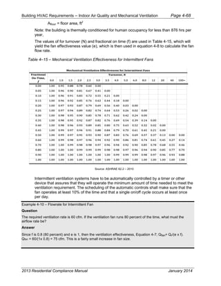
For the same house, if the fan runs half the day (12 hours per day), what is the required airflow?
Answer
The fractional on-time, f is 0.5 (50 percent), so e is also 0.5 from Table 4-15. The fan size, Qfan= 60/(0.5 x
0.5) = 240 cfm. This is a much larger increase in fan size.
Example 4-12
Question
For an apartment, the flow required is 45 cfm. If the ventilation fan runs 20 minutes on and 10 minutes off,
what is the required fan size?
Answer
Fractional on-time is 0.67 (67 percent). [f = on-time/total time = 20/(20 + 10)] Since the fan runs at least
once every three hours, is 1.0 (see Table 4-15). The fan size, Qfan = 45/(0.67 x 1.0) = 67.5 cfm, which
rounds to 68 cfm.
Example 4-13
Question
For the same apartment, if the fan runs 8 hours on and 4 hours off, what flow rate is required?
Answer
Fractional on-time is again 0.67 (67 percent, but now e is 0.75. Qfan= 45/(0.67 x 0.75) = 89.6 cfm, rounded
to 90 cfm.
Example 4-14
Question
I have an electronic timer system. I would like to have the system run only 2 hours in the morning and 8
hours in the evening (6 a.m. – 8 a.m. and 4 p.m. to midnight). I can set the timer to operate the fan for 1
minute every hour. What flow rate do I need?
Answer
Forget about the 1 minute every hour. ASHRAE has issued an interpretation of the standard that says that
operation such as you describe is not sufficient to use a ventilation effectiveness of 1. In this case, the
fractional on-time is 0.42 (10 hours/24 hours), so ventilation effectiveness from Table 4-15 is 0.5. Qfan= 60
cfm/(0.42 x 0.5) = 286 cfm.
D. Control and Operation
From ASHRAE 62.2-2010
2013 Residential Compliance Manual January 2014](https://image.slidesharecdn.com/cec-400-2013-001-cmf-rev2-151019231936-lva1-app6891/85/Cec-400-2013-001-cmf-rev2-pdf-243-320.jpg)
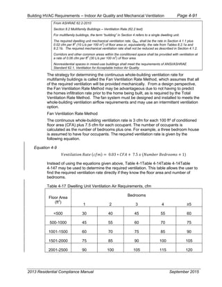
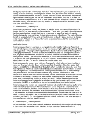
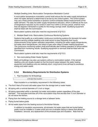
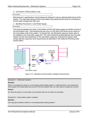
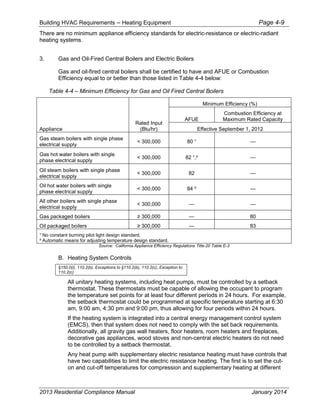
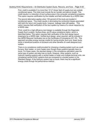
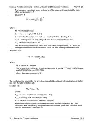
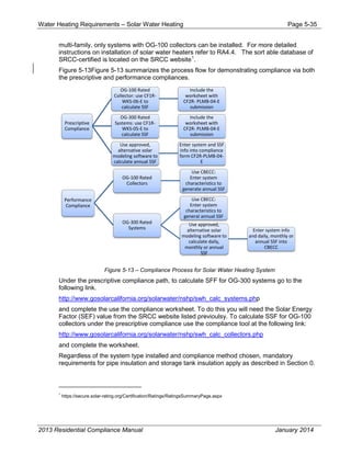
![Water Heating Requirements – Prescriptive Water Heater and Distribution System Requirements
Page 5-24
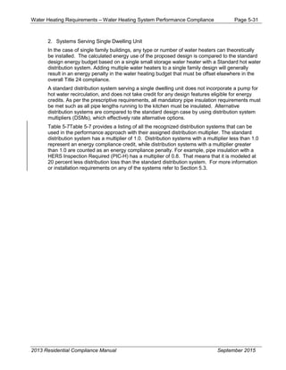
The other option under the prescriptive compliance method is to use the performance method
for water heating only as defined in §150.1(b)1 and which is discussed in full in the
performance compliance section later in this chapter. This path requires inputting the building
square footage and detailing the water heater and distribution system information into the
building performance compliance tool.
§150.1(c)8
With the changes in the 2013 standards there are actually three prescriptive options for
domestic hot water heating in single family residences depending upon whether natural gas
service is available at the site.
1. A system with a single gas or propane storage type water heater must have:
a) A gas input rating 75,000 Btu/h,
b) If the water heater’s efficiency only meets the minimum federal efficiency
standards, the tank must be wrapped with an R-12 water heating blanket [a
mandatory requirement in §150.0(j)1].
c) If the system uses a trunk and branch distribution system then all pipes from
the water heater to the kitchen must be insulated and all pipe with a diameter
equal to or greater than ¾ of an inch must be insulated.
d) If this system has a recirculation pump then the control must be demand based
with manual controls (pump only runs upon user direct activation until water
temperature equals temperature setpoint). All portions of the distribution
system that recirculate water must be insulated.
e) All applicable mandatory requirements in Section 110.3 and 150.0(j,n) must be
met.
2. A system with a single gas or propane instantaneous water heater without a storage tank
must have:
a) A gas input rating 200,000 Btu/h,
b) No supplemental storage tank is installed,
c) Uses a trunk and branch distribution system then all pipes from the water
heater to the kitchen must be insulated and all pipe with a diameter equal to or
greater than ¾ of a inch must be insulated.
d) All applicable mandatory requirements in Section 110.3 and 150.0(j,n) must
be met
3. An electric resistance storage or instantaneous water heater can be used if all of the
following conditions are met:
a) Natural gas is unavailable at the site
b) The water heater is located within the building envelope
c) For storage electric and instantaneous a trunk and branch distribution system
must have all pipes from the water heater to the kitchen and must be insulated
2013 Residential Compliance Manual June 20142015June 2014](https://image.slidesharecdn.com/cec-400-2013-001-cmf-rev2-151019231936-lva1-app6891/85/Cec-400-2013-001-cmf-rev2-pdf-325-320.jpg)
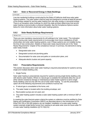
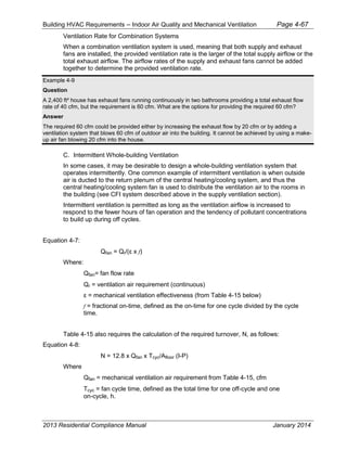
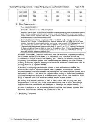
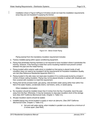
![Water Heating Requirements – Combined Hydronic System Page 5-43
3. Install built-up or built-in connections for future piping to solar water heating. An
example of this would be a capped off tee fitting.
Example 5-11 - Pool covers
Question
My pool has both a solar heater and a gas heater. Do I need to install a pool cover?
Answer
Yes. A cover is required for all pools with gas or electric heaters, regardless of whether they also have a solar
heater.
Example 5-12 - Pool pump
Question
I have a 25,000 gallon pool and want to use a two-speed pump with a Curve C flow rate of 79 gpm on high-
speed and 39 gpm on low-speed. Is this okay and what size piping must I installed?
Answer
The maximum filtration flow rate for a 25,000 gallon pool is 69 gpm by using equation [Max Flow Rate (gpm)
=Pool Volume (gallons) / 360 minutes], so the pump is adequately sized, as long as a control is installed to
operate the pump on low-speed for filtration. The maximum pipe size must be based on the maximum flow rate
of 79 gpm. Referencing Table 5-9, you must use 2.5 inch suction and 2 inch return piping.
5.8 Combined Hydronic System
5.8.1 Combined Hydronic
Combined hydronic space heating systems utilize a single heat source to provide both space
heating and domestic hot water. The current modeling of these system types is fairly
simplistic, treating water heating performance separately from the space heating function.
Section 4.7.1 provides an explanation of combined hydronic systems.
5.9 Shower Heads
5.9.1 Certification of Showerheads and Faucets
Maximum flow rates have historically been set by the Appliance Efficiency Regulations, and
all faucets and showerheads sold in California must meet these standards. California’s Title
20 Appliance Efficiency Regulations contains the maximum flow rate for showerheads and
lavatory and kitchen faucets. Current flow requirements contained in the Title 24 part 11
CALGreen Code set more efficiency levels. Installations of showerheads and faucets are
mandatory under the CALGreen Code and must be met.
2013 Residential Compliance Manual January 2014](https://image.slidesharecdn.com/cec-400-2013-001-cmf-rev2-151019231936-lva1-app6891/85/Cec-400-2013-001-cmf-rev2-pdf-344-320.jpg)


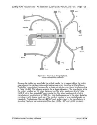
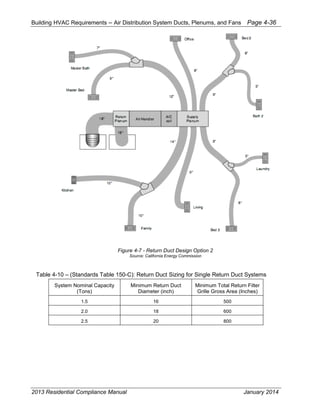
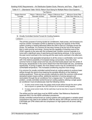
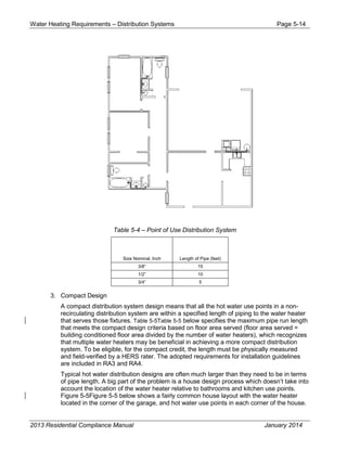
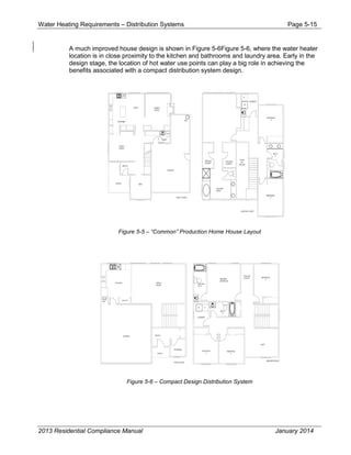
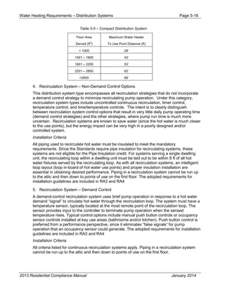
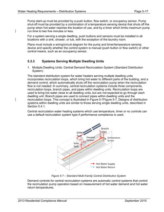
This document is the California Energy Commission's Residential Compliance Manual for the 2013 Building Energy Efficiency Standards (Title 24, Part 6). It provides guidance for complying with and enforcing California's energy efficiency standards for low-rise residential buildings. The manual covers topics like the building envelope, HVAC systems, water heating, lighting, and additions/alterations. It is intended to supplement the 2013 Energy Efficiency Standards and Reference Appendices.


