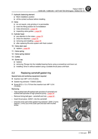
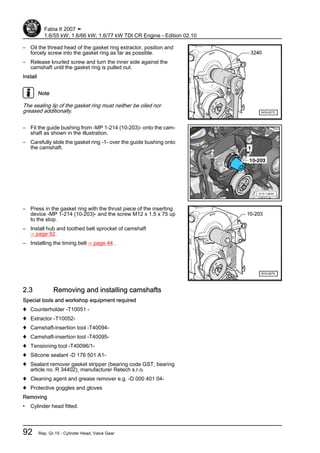
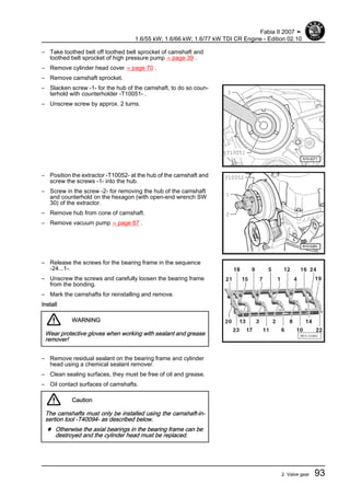
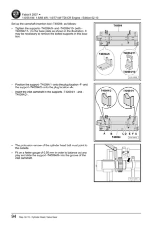
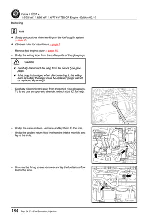
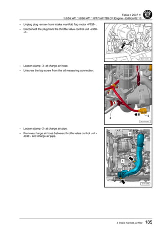
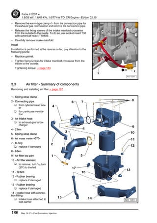
1. Workshop Manual
Fabia II 2007 ➤
1.6/55 kW; 1.6/66 kW; 1.6/77 kW TDI CR Engine
Engine ID
CAY
A
CAY
B
CAY
C
Edition 02.10
Service
Service Department. Technical Information
2. List of Workshop Manual Repair GroupsList of Workshop Manual
Repair GroupsList of Workshop Manual Repair Groups
Repair Group
00 - Technical data
01 - Self-diagnosis
10 - Removing and installing engine
13 - Crankgear
15 - Cylinder Head, Valve Gear
17 - Lubrication
19 - Cooling
20 - Fuel Supply
21 - Turbocharging
23 - Fuel Formation, Injection
26 - Exhaust System
28 - Glow Plug System
Technical information should always be available to the foremen and mechanics, because their
careful and constant adherence to the instructions is essential to ensure vehicle road-worthiness and
safety. In addition, the normal basic safety precautions for working on motor vehicles must, as a
matter of course, be observed.
Service
7. 00 – Technical data
1 Technical data
1.1 Engine number
The engine number (“engine identification characters” and “serial
number”) is located at the engine/gearbox joint -arrow-.
In addition, a sticker with the “engine identification character” and
“serial number” is affixed to the toothed belt guard.
The engine code is also indicated on the vehicle data sticker.
♦ The engine identification characters have 4 digits starting with
the letter “C”.
♦ The first 3 digits of the engine identification characters refer to
the displacement and the mechanical construction of the en‐
gine. They are type-punched in the cylinder block including the
serial number.
♦ The fourth digit indicates the output and the torque of the en‐
gine and depends upon the engine control unit.
1.2 Engine characteristics
Engine identifica‐
tion character
CAYA CAYB CAYC
Manufac‐
tured
03.10 ? 03.10 ? 03.10 ?
Exhaust limit val‐
ues conforming to
EU5 EU5 EU5
Displace‐
ment
l 1598 1598 1598
Power out‐
put
kW at
rpm
55/4000 66/4200 77/4400
Torque Nm at
rpm
195/1500...2000 230/1500...2500 250/1500...2500
Bore ∅ mm 79,5 79,5 79,5
Stroke mm 80,5 80,5 80,5
Number of valves
per cylinder
4 4 4
Compression ratio 16,5 16,5 16,5
Firing order 1-3-4-2 1-3-4-2 1-3-4-2
Catalytic
converter
yes yes yes
Exhaust gas recir‐
culation with radia‐
tor
yes yes yes
Turbo‐
charging
yes yes yes
Charge air cooler yes yes yes
Diesel particle fil‐
ter
yes yes yes
Fabia II 2007 ➤
1.6/55 kW; 1.6/66 kW; 1.6/77 kW TDI CR Engine - Edition 02.10
1. Technical data 1
Volkswagen Technical Site: http://vwts.ru http://vwts.info
8. 01 – Self-diagnosis
1 Self diagnosis, safety measures,
cleanliness regulations and direc‐
tions
1.1 Self-diagnosis
This repair group is no longer applicable.
For this use “Vehicle self-diagnosis”, “Measuring method” and
“Targeted fault finding” ⇒ Vehicle diagnosis, testing and informa‐
tion system VAS 5051.
1.2 Supplementary instructions and assem‐
bly work on vehicles with an air condi‐
tioning system
WARNING
Refrigerant circuit of the air conditioning system must not be
opened.
Caution
Risk of damaging the condenser and the refrigerant lines as
well as the refrigerant hoses.
♦ Do not over-tension, buckle or bend refrigerant lines and
refrigerant hoses.
Steps which should be taken in order to remove and install the
engine without opening the refrigerant circuit:
– Unscrew the holding clamp(s) on the refrigerent lines
– Remove V-ribbed belt ⇒ page 31 .
– Remove AC compressor from the bracket for auxiliary units
⇒ page 24 .
– Mount the air conditioning compressor and the condenser in
such a way that the refrigerent lines/hoses are not under ten‐
sion.
Fabia II 2007 ➤
1.6/55 kW; 1.6/66 kW; 1.6/77 kW TDI CR Engine - Edition 02.10
2 Rep. Gr.01 - Self-diagnosis
9. 1.3 Safety precautions when working on the
fuel supply system
WARNING
♦ The fuel or the fuel lines in the fuel system can become
very hot (risk of scalding)!
♦ The fuel system is under pressure!
♦ Wear safety goggles and safety clothing, in order to avoid
injuries and skin contact with fuel.
♦ Place cleaning cloths around the connection point before
detaching cable connections. Reduce pressure by care‐
fully removing the wiring.
Fabia II 2007 ➤
1.6/55 kW; 1.6/66 kW; 1.6/77 kW TDI CR Engine - Edition 02.10
1. Self diagnosis, safety measures, cleanliness regulations and directions 3
10. ♦ The fuel pump is activated when the ignition is switched on
and by the door contact switch of the driver door. Before open‐
ing the fuel system and for reasons of safety, if the battery is
not disconnected, the connector -arrow- must be disconnected
from the fuel delivery unit.
WARNING
When undertaking all installation work, particularly in the en‐
gine compartment due to its cramped construction, please
observe the following:
♦ Lay lines of all kinds (e.g. for fuel, hydraulic fluid, cooling
fluid and refrigerant, brake fluid, vacuum) and electrical
lines in such a way that the original line guide is re-estab‐
lished.
♦ Ensure that there is adequate free access to all moving or
hot components.
Caution
In order to avoid the fuel high pressure pump to run dry and to
achieve a quick engine start after parts are replaced, the fol‐
lowing must absolutely be observed:
♦ If parts of the fuel system were removed or replaced, it is
necessary to initiate the basic setting “check fuel pump” in
order to vent the fuel system ⇒ Vehicle diagnosis, testing
and information system VAS 5051.
♦ If the fuel pump, fuel line or fuel filter were removed or
replaced, the basic setting “check fuel pump” must be in‐
itiated “once” before the first engine start.
♦ If the fuel high pressure pump is removed, the basic set‐
ting “test of fuel pump for predelivery” must be carried out
“3 times” before the first engine start.
♦ If the fuel high pressure pump is replaced, the initial fuel
filling of the fuel high pressure pump must be carried out
before the first engine start ⇒ page 179 .
When removing and installing the fuel gauge sender or the fuel
delivery unit from a full or partly filled fuel tank, pay attention to
the following points:
♦ The extraction hose of an exhaust extraction system which is
switched on, must be positioned close to the assembly open‐
ing of the fuel tank in order to extract the released fuel vapours,
even before the work is commenced. If no exhaust extraction
system is available, a radial fan (motor not in air flow of fan)
with a delivery volume of more than 15 m3/h must be used.
♦ Avoid skin contact with fuel! Wear fuel-resistant gloves!
Fabia II 2007 ➤
1.6/55 kW; 1.6/66 kW; 1.6/77 kW TDI CR Engine - Edition 02.10
4 Rep. Gr.01 - Self-diagnosis
11. 1.4 Safety precautions when working on the
fuel supply of the diesel direct injection
system
WARNING
When undertaking all installation work, particularly in the en‐
gine compartment due to its cramped construction, please
observe the following:
♦ Lay lines of all kinds (e.g. for fuel, hydraulic fluid, cooling
fluid and refrigerant, brake fluid, vacuum) and electrical
lines in such a way that the original line guide is re-estab‐
lished.
♦ Ensure that there is adequate free access to all moving or
hot components.
♦ The fuel or the fuel lines in the fuel system can become
very hot (risk of scalding)!
♦ The fuel system is under pressure!
♦ Wear safety goggles and safety clothing, in order to avoid
injuries and skin contact with fuel.
♦ Place cleaning cloths around the connection point before
detaching cable connections. Reduce pressure by care‐
fully removing the wiring.
Caution
In order to avoid the fuel high pressure pump to run dry and to
achieve a quick engine start after parts are replaced, the fol‐
lowing points must be observed:
♦ If parts of the fuel system were removed or replaced, it is
necessary to initiate the basic setting “check fuel pump” in
order to vent the fuel system ⇒ Vehicle diagnosis, testing
and information system VAS 5051.
♦ If the fuel pump, fuel line or fuel filter were removed or
replaced, the basic setting “check fuel pump” must be in‐
itiated “once” before the first engine start.
♦ If the fuel high pressure pump is removed, the basic set‐
ting “test of fuel pump for predelivery” must be carried out
“3 times” before the first engine start.
♦ If the fuel high pressure pump is replaced, the initial fuel
filling of the fuel high pressure pump must be carried out
before the first engine start ⇒ page 179 .
If test and measuring devices are required during test drives ob‐
serve the following:
♦ Always secure the test and measuring devices on the rear seat
and have a second person operate them there.
If the test and measuring devices are operated from the passen‐
ger seat, the passenger can be injured by the release of the
passenger airbag in the event of an accident.
Fabia II 2007 ➤
1.6/55 kW; 1.6/66 kW; 1.6/77 kW TDI CR Engine - Edition 02.10
1. Self diagnosis, safety measures, cleanliness regulations and directions 5
12. WARNING
Secure the diagnostic device to the rear seat and operate from
that position.
Observe the following points to prevent injury to persons and/or
damage to the injection and preheating system:
♦ Disconnect and connect wires of the preheating and injection
system as well as measuring device wires when the ignition is
switched off.
♦ If the engine must be operated, without it starting, unplug the
connector -5- at the fuel pressure regulating valve -N276- .
♦ Before disconnecting the battery determine the code of the
radio fitted with anti-theft coding.
♦ Always switch off the ignition before disconnecting and re-
connecting the battery. Otherwise the engine control unit may
be damaged.
♦ If the battery is connected, carry out certain additional opera‐
tions ⇒ Electrical System ⇒ Rep. Gr. 27 .
1.5 Regulations concerning cleanliness
when working on the fuel supply/fuel in‐
jection system
Carefully observe the following “6 rules” for cleanliness when
working on the fuel supply/injection system:
♦ Thoroughly clean the connection points and their surroundings
before releasing.
♦ Place removed parts on a clean surface and cover. Do not use
fuzzy cloths!
♦ Carefully cover or close opened components if the repair is not
completed immediately.
♦ Only install clean parts: Remove spare parts from their wrap‐
ping immediately before installing. Do not use any parts which
have been stored unwrapped (e.g. on a shelf or in a tool box).
♦ When the system is opened: do no use compressed air. Do
not use the vehicle.
♦ Also make sure no diesel fuel runs onto the coolant hoses. If
this is the case clean the hoses immediately. Replace imme‐
diately any hoses which have suffered damage.
1.6 Regulations concerning cleanliness
when working on the exhaust gas turbo‐
charger
Carefully observe the following “5 rules” for cleanliness when
working on the exhaust gas turbocharger:
♦ Thoroughly clean the connection points and their surroundings
before releasing.
♦ Place removed parts on a clean surface and cover. Do not use
fuzzy cloths!
♦ Carefully cover or close opened components if the repair is not
completed immediately.
Fabia II 2007 ➤
1.6/55 kW; 1.6/66 kW; 1.6/77 kW TDI CR Engine - Edition 02.10
6 Rep. Gr.01 - Self-diagnosis
13. ♦ Only install clean parts: Remove spare parts from their wrap‐
ping immediately before installing. Do not use any parts which
have been stored unwrapped (e.g. on a shelf or in a tool box).
♦ When the system is opened: do no use compressed air. Do
not use the vehicle.
1.7 General instructions for charge air sys‐
tem
WARNING
When undertaking all installation work, particularly in the en‐
gine compartment due to its cramped construction, please
observe the following:
♦ Lay lines of all kinds (e.g. for fuel, hydraulic fluid, cooling
fluid and refrigerant, brake fluid, vacuum) and electrical
lines in such a way that the original line guide is re-estab‐
lished.
♦ Ensure that there is adequate free access to all moving or
hot components.
Caution
In case a mechanical damage to the exhaust gas turbocharger
is found, e.g. damage to the compressor wheel, it is not suffi‐
cient to only replace the turbocharger. In order to avoid con‐
sequential damage, perform the following tasks:
♦ Clean all oil lines.
♦ Change the engine oil and replace the oil filter
♦ Check air filter housing, air filter element and charge air
pipes as well as charge air hoses for soiling.
♦ Check all air guides and charge air cooler for foreign bod‐
ies.
If foreign bodies are detected in the charge air system, the
charge-air routing must be cleaned and the charge air cooler
must be replaced.
♦ The charge-air system must be tight, check ⇒ page 157 .
♦ Replace the gaskets, the sealing rings and the self-locking
nuts.
♦ Hose connections and hoses for the charge air system must
be free of oil and grease before being installed.
♦ Observe markings on the hoses and components.
♦ All hose connections of the charge air system are secured with
spring strap clips.
♦ Only install approved clamps for securing the hose connec‐
tions ⇒ Electronic Catalogue of Original Parts .
♦ Use pliers for spring strap clamps to fit the spring strap clips.
♦ Before screwing down the oil feed line, fill the exhaust turbo‐
charger via the connection fitting with engine oil.
♦ After installing the turbocharger, run engine at idling speed for
about 1 minute to ensure that oil is supplied to the turbocharg‐
er.
Fabia II 2007 ➤
1.6/55 kW; 1.6/66 kW; 1.6/77 kW TDI CR Engine - Edition 02.10
1. Self diagnosis, safety measures, cleanliness regulations and directions 7
14. 10 – Removing and installing engine
1 Removing and installing engine
1.1 Removing engine
Special tools and workshop equipment required
♦ Engine mount -T10012-
♦ Engine and gearbox jack , e.g. -V.A.G 1383 A-
♦ Catch pan for workshop crane , e.g. -VAS 6208-
♦ Double ladder , e. g. -VAS 5085-
♦ Pliers for spring strap clamps
Note
♦ The engine is removed downwards together with the gearbox.
♦ All cable straps that have been loosened or cut open when the
engine was removed must be attached again in the same lo‐
cation when the engine is installed again.
♦ Collect drained coolant in a clean container for proper disposal
or reuse.
Caution
When undertaking all installation work, particularly in the en‐
gine compartment due to its cramped construction, please
observe the following:
♦ Lay lines of all kinds (e.g. for fuel, hydraulic fluid, cooling
fluid and refrigerant, brake fluid, vacuum) and electrical
lines in such a way that the original line guide is re-estab‐
lished.
♦ In order to avoid damage to the cables, ensure that there
is adequate free access to all moving or hot components.
Observe all safety measures and notes for assembly work on the
fuel and injection system, the charge air system as well as the
rules for cleanliness ⇒ page 2 .
– If present, remove the adapter for the safety wheel bolts from
the luggage compartment.
– Remove front wheels ⇒ Chassis ⇒ Rep. Gr. 44 .
– Disconnect the battery-earth strap with the ignition off ⇒ Elec‐
trical System ⇒ Rep. Gr. 27 .
– Remove top engine cover ⇒ page 15 .
– Remove air filter housing with air mass meter -G70- and suc‐
tion hose ⇒ page 187 .
– Remove battery and battery tray ⇒ Electrical System ⇒ Rep.
Gr. 27 .
Fabia II 2007 ➤
1.6/55 kW; 1.6/66 kW; 1.6/77 kW TDI CR Engine - Edition 02.10
8 Rep. Gr.10 - Removing and installing engine
15. – Release plug -3- from charge pressure control solenoid valve
-N75 - .
– Unscrew charge pressure control solenoid valve -N75- with
fixture -2- and place it on the engine.
– Remove the gearshift mechanism from the gearbox ⇒ Gear‐
box ⇒ Rep. Gr. 34 .
– Remove clutch slave cylinder from gearbox ⇒ Gearbox ⇒
Rep. Gr. 30 .
WARNING
After removing the slave cylinder, do not depress the clutch
pedal.
– Remove the vacuum hose -arrow- from the brake servo unit.
– Unlatch the fuse and disconnect the front plug from the engine
control unit ⇒ page 189 .
– Disconnect plug connection -arrow-.
– Carefully slacken the engine wiring harness on its fixing points
-arrows-.
– Place the engine wiring harness on the engine.
Fabia II 2007 ➤
1.6/55 kW; 1.6/66 kW; 1.6/77 kW TDI CR Engine - Edition 02.10
1. Removing and installing engine 9
16. – Unscrew the positive cable to the generator -1-, unclip and
place on the gearbox.
– Unscrew the cable from the starter and the gearbox and re‐
move it.
– Release screws -1 ... 3- and remove pendulum support.
– Remove pre-exhaust pipe with diesel particle filter
⇒ page 194 .
– Separate fuel feed line -2- and fuel return-flow line -1-, to do
so press the release buttons.
– Unlock the catch peg with a finger and pull the fuel preheating
valve upwards out of the guide of the coolant expansion bottle.
Fabia II 2007 ➤
1.6/55 kW; 1.6/66 kW; 1.6/77 kW TDI CR Engine - Edition 02.10
10 Rep. Gr.10 - Removing and installing engine
17. – Push the catch pegs up and remove the fuel filter towards the
top.
– Place the fuel filter and the fuel hoses together with the fuel
preheating valve on the engine.
– Remove fuel filter bracket.
– Remove the right and left wheelhouse liner ⇒ Body Work ⇒
Rep. Gr. 66 .
– Unscrew the nuts from the right steering joint -arrows- and
press the steering joint out of the suspension arm.
– Remove drive shaft cover.
– Remove right drive shaft from gearbox and secure with wire
⇒ Chassis ⇒ Rep. Gr. 40 .
– Disconnect left drive shaft from gearbox ⇒ Chassis ⇒ Rep.
Gr. 40 .
– Unscrew the nut from the left coupling rod -2- of the anti-roll
bar and press the coupling rod off the anti-roll bar.
– Unscrew the nuts from the left steering joint -3- and press the
steering joint out of the suspension arm.
– If present, remove the front left vehicle level sensor -G78- ⇒
Chassis ⇒ Rep. Gr. 40 .
– Turn the wheel bearing housing to the left up to the stop.
– Swivel the steering joint outwards and secure the drive shaft
-1- with a band -A- in the wheelhouse.
– Remove right charge air hose.
Fabia II 2007 ➤
1.6/55 kW; 1.6/66 kW; 1.6/77 kW TDI CR Engine - Edition 02.10
1. Removing and installing engine 11
18. – Release screws -arrows-.
– Loosen hose clamp -2-.
– Disconnect the plug -1- at the charge pressure sender -G31-
with intake air temperature sender -G42- and remove the right
charge air pipe.
– Drain coolant ⇒ page 117 .
– Remove the remaining coolant hoses from the radiator.
– Remove the earth connection -1- from the assembly bearing.
– Remove coolant expansion bottle and place on the engine.
– Unclip the filler neck of the windshield washer reservoir -1- and
lay to the side.
On vehicles with air conditioning
– Remove alternator ⇒ Electrical System ⇒ Rep. Gr. 27 .
WARNING
Risk of injury through refrigerant.
♦ Do not open the refrigerant circuit of the air conditioning
system.
Caution
Risk of damaging the condenser and the refrigerant lines as
well as the refrigerant hoses.
♦ Do not over-tension, buckle or bend refrigerant lines and
refrigerant hoses.
– Remove the AC compressor from the bracket for auxiliary
units ⇒ Heating, Air Conditioning ⇒ Rep. Gr. 87 .
Fabia II 2007 ➤
1.6/55 kW; 1.6/66 kW; 1.6/77 kW TDI CR Engine - Edition 02.10
12 Rep. Gr.10 - Removing and installing engine
19. – Attach the AC compressor -3- e.g. behind the lock carrier as
shown in the figure. As protection put a sheet of cardbord -1-
on the radiator wall.
Continued for all vehicles
– Remove noise insulation of oil pan -1-, to do so slacken the
fixing parts -arrows-.
– Unscrew screw -1- and push the coolant recirculation pump 2
-V178- -3- to the side.
– Disconnect all further necessary plugs at the engine and gear‐
box or separate the lines to the engine and gearbox.
– Separate the quick couplings -arrows- at the heat exchanger.
– Unclamp all remaining connecting, coolant, vacuum and suc‐
tion hoses from the engine.
– Release all remaining plugs at engine and gearbox and lay
aside the relevant lines.
Fabia II 2007 ➤
1.6/55 kW; 1.6/66 kW; 1.6/77 kW TDI CR Engine - Edition 02.10
1. Removing and installing engine 13
20. – Screw engine mount -T10012- to the cylinder block with nut
-2- and screw -1- to 20 Nm.
– Insert engine/gearbox jack -V.A.G 1383 A- in the engine
mount and slightly raise.
Note
Use double ladder to release the screws for the engine/gearbox
mounting.
– Release the screws which connect the engine mount with the
engine support -arrows-.
– Remove the assembly bracket at the gearbox. Release
screws -arrows-.
Note
♦ Check whether all hose and line connections between engine,
gearbox and body are released.
♦ When lowering carefully guide the engine with the gearbox, in
order to avoid damage.
♦ Ensure the necessary space for lowering the assembly by
pressing off the assembly carrier.
– Carefully lower engine with gearbox. During this procedure,
turn or move the engine with the gearbox depending upon the
constriction.
– Remove the gearbox from the engine.
Fabia II 2007 ➤
1.6/55 kW; 1.6/66 kW; 1.6/77 kW TDI CR Engine - Edition 02.10
14 Rep. Gr.10 - Removing and installing engine
21. 1.1.1 Removing and installing engine trim
panel
Removing
– Pull the engine cover at the corners -arrows- upwards with a
sudden motion and through this slacken it.
Install
Caution
Before installing the engine cover, check the correct position
of the 4 fixing elements (ball sockets). If necessary they must
be put back into their position. Otherwise this can lead to dam‐
age to the engine cover.
– Position the engine cover onto the fixing points and press it in
at the corners until it clicks into place.
1.2 Securing the engine to the assembly
stand
Special tools and workshop equipment required
♦ Engine mount -MP 1-202- or -VAS 6095-
♦ Hook -MP 1-202/10-
♦ Assembly stand -MP 9-101-
♦ Lifting device -MP 9-201 (2024A)-
♦ Bushing -T30010 (VW 540/1B)-
♦ Workshop crane , e.g. -VAS 6100-
• Separate engine from gearbox.
WARNING
Use securing pins on the hooks and rig pins to prevent release.
– Attach lifting device -MP 9-201- at engine and at workshop
crane e.g. -VAS 6100- .
On the belt pulley side:
♦ 2. Hole of the attachment in Position 1
On the flywheel side:
♦ 4. Hole of the attachment in Position 8
Note
The illustration shows the pump injector engine. The attachment
for the Common Rail engine occurs in the same way.
– Lift off engine with installed engine mount -T10012- with work‐
shop crane from engine/gearbox jack.
– Remove engine mount -T10012 - .
Fabia II 2007 ➤
1.6/55 kW; 1.6/66 kW; 1.6/77 kW TDI CR Engine - Edition 02.10
1. Removing and installing engine 15
22. – For carrying out assembly work, attach the engine with engine
mount -MP 1-202- , hooks -MP 1-202/10- and sleeves -
T30010- or engine mount -VAS 6095- to the assembly stand
-MP 9-101- . The figure shows the 1.9 ltr./47 kW SDI Engine.
The fixing system is identical.
1.3 Installing the engine
Special tools and workshop equipment required
♦ Grease -G 000 100- for manual gearbox
• Mount engine and gearbox using engine mount onto engine/
gearbox jack .
Installation is performed in the reverse order, pay attention to the
following points:
Note
♦ Observe all safety measures and notes for assembly work on
the fuel and injection system, the charge air system as well as
the rules for cleanliness ⇒ page 2 .
♦ When undertaking assembly replace self-locking nuts and
screws which have been tightened to a torquing angle.
♦ Always replace gasket rings and seals.
♦ All cable straps should be fastened again in the same place
when installing.
♦ Secure all hose connections with corresponding hose clamps
⇒ Electronic Catalogue of Original Parts .
Caution
When undertaking all installation work, particularly in the en‐
gine compartment due to its cramped construction, please
observe the following:
♦ Lay lines of all kinds (e.g. for fuel, hydraulic fluid, cooling
fluid and refrigerant, brake fluid, vacuum) and electrical
lines in such a way that the original line guide is re-estab‐
lished.
♦ In order to avoid damage to the cables, ensure that there
is adequate free access to all moving or hot components.
Fabia II 2007 ➤
1.6/55 kW; 1.6/66 kW; 1.6/77 kW TDI CR Engine - Edition 02.10
16 Rep. Gr.10 - Removing and installing engine
23. Note
♦ Clean the serration of the drive shaft and if the clutch disc has
been used clean the hub serration, remove corrosion and only
apply a very thin layer of grease -G 000 100- on the serration.
Subsequently move the clutch disc up and down on the drive
shaft until the hub fits smoothly on the shaft. Always remove
excess grease.
♦ After installing the coupling, check the centering of the clutch
disc ⇒ gearbox ⇒ Rep. Gr. 30 .
♦ Check the clutch release bearing for wear. Replace release
bearing if worn ⇒ gearbox ⇒ Rep. Gr. 30 .
– Check whether the dowel sleeves for centering the engine/
gearbox are present in the cylinder block; insert if necessary.
– Ensure that the intermediate plate has been inserted on the
sealing flange and is pushed onto the dowel sleeves
-arrows-.
– Screw on gearbox to engine ⇒ gearbox ⇒ Rep. Gr. 34 .
– Insert engine with gearbox into the body.
– Successively screw in by hand the screws for engine mounting
-arrows-.
– Successively screw in by hand the screws for gearbox mount‐
ing -arrows-.
– Remove engine mount -T10012- from engine.
– Install pre-exhaust pipe with diesel particle filter
⇒ page 194 .
Fabia II 2007 ➤
1.6/55 kW; 1.6/66 kW; 1.6/77 kW TDI CR Engine - Edition 02.10
1. Removing and installing engine 17
24. – Screw down pendulum support with new screws -2- and -3- at
gearbox and then screw down with new screw -1- at assembly
carrier.
– Install the left and right drive shaft ⇒ Chassis ⇒ Rep. Gr. 40 .
– Install the slave cylinder, if necessary bleed the clutch control
⇒ Gearbox ⇒ Rep. Gr. 30 .
– Attach the shift mechanism to the gearbox and adjust ⇒ Gear‐
box ⇒ Rep. Gr. 34 .
– Attach AC compressor to holder for auxiliary units
⇒ page 24 .
– Install alternator ⇒ Electrical System ⇒ Rep. Gr. 27 .
– Install the V-ribbed belt ⇒ page 31 .
– Connect all hoses to the engine.
– Connect electrical connections and attach cables ⇒ Current
flow diagrams and Fitting locations.
– Carry out cohesive work when reconnecting the battery ⇒
Electrical System ⇒ Rep. Gr. 27 .
– Top up coolant ⇒ page 117 .
– Checking the oil level ⇒ Maintenance ; Fabia II .
– Install the left and right wheelhouse liner ⇒ Body Work ⇒ Rep.
Gr. 66 .
– Install the noise insulation ⇒ Body Work ⇒ Rep. Gr. 50 .
Caution
♦ If parts of the fuel system were removed or replaced, it is
necessary to initiate the basic setting “check fuel pump” in
order to vent the fuel system ⇒ Vehicle diagnosis, testing
and information system VAS 5051.
– Perform a test drive.
– Interrogate all fault memories, rectify any faults existing and
erase fault memory ⇒ Vehicle diagnosis, testing and informa‐
tion system VAS 5051.
Note
After deleting the fault memory of the engine control unit the read‐
iness code must be re-generated.
Tightening torques
Component Nm
Screws or nuts M6 10
M7 15
M8 20
M10 40
M12 70
Engine/gearbox connecting screws ⇒
gearbox ⇒ Rep. Gr. 34
Fabia II 2007 ➤
1.6/55 kW; 1.6/66 kW; 1.6/77 kW TDI CR Engine - Edition 02.10
18 Rep. Gr.10 - Removing and installing engine
25. 1.4 Assembly bracket
Tightening torques
Engine mount
1 - not fitted on this type of engine
2 - 20 Nm + 90° (1/4 turn) - replace
3 - 30 Nm + 90° (1/4 turn) - replace
4 - 16 Nm
Gearbox mount
1 - 50 Nm + 90° (1/4 turn) - replace
2 - 40 Nm + 90° (1/4 turn) - replace
Pendulum support
Note
Position the screws -1- in the elongated holes of the pendulum
support in such a way that there is maximum distance between
the gearbox and the assembly carrier.
1 - 30 Nm + 90° (1/4 turn) - replace
2 - 40 Nm + 90° (1/4 turn) - replace
1.5 Removing and installing engine support
Special tools and workshop equipment required
♦ Supporting device -MP9-200 (10-222A)-
Fabia II 2007 ➤
1.6/55 kW; 1.6/66 kW; 1.6/77 kW TDI CR Engine - Edition 02.10
1. Removing and installing engine 19
26. Removing
Caution
When undertaking all installation work, particularly in the en‐
gine compartment due to its cramped construction, please
observe the following:
♦ Lay lines of all kinds (e.g. for fuel, hydraulic fluid, cooling
fluid and refrigerant, brake fluid, vacuum) and electrical
lines in such a way that the original line guide is re-estab‐
lished.
♦ In order to avoid damage to the cables, ensure that there
is adequate free access to all moving or hot components.
Note
♦ Safety precautions when working on the fuel supply system
⇒ page 3 .
♦ Observe rules for cleanliness ⇒ page 6 .
– Switch off ignition and withdraw ignition key.
– Remove top engine cover ⇒ page 15 .
– Remove vacuum line from brake servo unit -arrow-.
– Install supporting device -MP9-200 (10-222A)- and support
the engine with spindle -B- in fitting position. Allow spindle
-A- to hang loosely.
Note
♦ The assembly bearing must only be removed if the engine is
supported with the supporting device -MP9-200 (10-222A)- !
♦ Only release the engine support if the assembly bearing is re‐
moved.
– Remove the front right wheelhouse liner ⇒ Body Work ⇒ Rep.
Gr. 66 .
Fabia II 2007 ➤
1.6/55 kW; 1.6/66 kW; 1.6/77 kW TDI CR Engine - Edition 02.10
20 Rep. Gr.10 - Removing and installing engine
27. – Separate fuel feed line -2- and fuel return-flow line -1-, to do
so press the release buttons.
– Collect the fuel which flows out.
– Unlock the catch peg with a finger and pull the fuel preheating
valve upwards out of the guide of the coolant expansion bottle.
– Unclip the fuel line from the plastic holders.
– Push the catch pegs up and remove the fuel filter towards the
top.
– Place the fuel filter and the fuel hoses together with the fuel
preheating valve on the engine.
– Remove fuel filter bracket.
– Slacken the coolant expansion bottle in such a way that there
is sufficient space for the removal of the engine support.
– Remove top part of toothed belt guard; to do so release re‐
taining clips -arrows-.
– Remove the earth connection from the assembly bracket.
Fabia II 2007 ➤
1.6/55 kW; 1.6/66 kW; 1.6/77 kW TDI CR Engine - Edition 02.10
1. Removing and installing engine 21
28. – Release the fixing screws of the assembly/engine support
bracket -3-, assembly/body bracket -2- and remove the entire
assembly bracket.
– Release screws -1 ... 3- and remove pendulum support.
WARNING
Make sure that no components as well as hoses are damaged,
overstretched or torn off when lifting and lowering the engine
with the supporting device -MP9-200 (10-222A)- .
– Pull the engine as far as possible towards the radiator.
Note
Remove the fixing screw -1- together with the engine support.
Raise the engine and lower it via the spindle of the supporting
device -MP9-200 (10-222A)- so that the screws -2- and -3- can
be removed or inserted.
– Unscrew the fixing screws for the engine support in the se‐
quence -3 - 2 - 1-.
– Remove the engine support upwards.
Install
Caution
The tightening sequence and the tightening torque of the fixing
screws for the engine support must definitely be respected.
Otherwise stress of the engine support occurs, which results
in the breaking of the engine support.
Installation occurs in reverse order. However, pay attention to the
following:
– Place the engine support from the top.
Fabia II 2007 ➤
1.6/55 kW; 1.6/66 kW; 1.6/77 kW TDI CR Engine - Edition 02.10
22 Rep. Gr.10 - Removing and installing engine
29. Note
Install the fixing screw -1- together with the engine support. Raise
the engine and lower it via the spindle of the supporting device -
MP9-200 (10-222A)- so that the screws -2- and -3- can be re‐
moved or inserted.
– Tighten the fixing screws in the tightening sequence
-1 - 2 - 3-: 7 Nm
– Tighten the fixing screws in the tightening sequence
-1 - 2 - 3-: 40 Nm + torque a further 180° (1/2 turn).
– Install engine mounting with new screws.
– Tighten screws for engine mount ⇒ page 19 .
Further installation occurs in reverse order. However, pay atten‐
tion to the following:
♦ Make sure the fuel lines fit tightly.
♦ Do not mix-up the feed line and the return-flow line (the return-
flow line is blue or has a blue marking, the feed line is black).
Fabia II 2007 ➤
1.6/55 kW; 1.6/66 kW; 1.6/77 kW TDI CR Engine - Edition 02.10
1. Removing and installing engine 23
30. 13 – Crankgear
1 Removing and installing a V-ribbed
belt and a toothed belt
1.1 Removing and installing V-ribbed belt
1.1.1 Summary of components - Vehicles without air conditioning
1 - Belt pulley/vibration damp‐
ener
❑ pay attention to correct
installation position
⇒ page 25
❑ removing and installing
⇒ page 32
2 - 25 Nm
3 - AC generator
❑ removing and installing
⇒ Electrical System ⇒
Rep. Gr. 27
4 - Bracket for auxiliary units
❑ removing and installing
⇒ page 35
5 - V-ribbed belt
❑ removing and installing
⇒ page 29
❑ replace
❑ pay attention to the cor‐
rect position on the belt
pulley when installing it.
Fabia II 2007 ➤
1.6/55 kW; 1.6/66 kW; 1.6/77 kW TDI CR Engine - Edition 02.10
24 Rep. Gr.13 - Crankgear
31. Fitting position of the V-ribbed belt on the crankshaft
• The hole -arrow- in the V-ribbed belt on the crankshaft must
be positioned above the peg on the toothed belt sprocket of
the crankshaft.
Bracket for auxiliary units - tightening order and tightening torques
• A dowel sleeve must be located between the bracket for aux‐
iliary units and the cylinder block in the area of the screw hole
-6-.
– Insert new fixing screws for the bracket for auxiliary units as
follows:
♦ Screws -1- and -2- M10 x 52
♦ Screws -3- and -4- M10 x 30
♦ Screws -5- and -6- M10 x 60
– Gradually tighten the fixing screws for the bracket for auxiliary
units in the sequence -1…6-:
1. Screw in all the screws by hand.
2. Tighten all screws to 40 Nm.
3. Turn the screws -3- and -4- a further 45°.
4. Turn the screws -1, 2, 5, 6- a further 90°.
Fabia II 2007 ➤
1.6/55 kW; 1.6/66 kW; 1.6/77 kW TDI CR Engine - Edition 02.10
1. Removing and installing a V-ribbed belt and a toothed belt 25
32. 1.1.2 Summary of components - Vehicles with air conditioning and guide pulley
1 - V-ribbed belt
❑ removing and installing
⇒ page 30
❑ check for wear
❑ mark the direction of ro‐
tation with chalk or a felt-
tip pen before removing
❑ do not kink
❑ pay attention to the cor‐
rect position on the belt
pulley when installing it.
2 - Guide pulley for V-ribbed
belt
❑ removing and installing
⇒ page 30
3 - Belt pulley for crankshaft
❑ with vibration damper
❑ pay attention to correct
installation position
⇒ page 27
❑ removing and installing
⇒ page 32
4 - 10 Nm + torque a further 90°
(1/4 turn)
❑ replace
5 - Fitting sleeve
❑ pay attention to correct
fit in the bracket for aux‐
iliary units
❑ the dowel sleeve is lo‐
cated in the top right
screw hole ⇒ page 27
6 - 20 Nm + torque a further 45°
(1/8 turn)
7 - 50 Nm + torque a further 90° (1/4 turn)
8 - Guide pulley
❑ for toothed belt
9 - 15 Nm
10 - Guide pulley
❑ for toothed belt
11 - Bracket for auxiliary units
❑ removing and installing ⇒ page 35
12 - High pressure pump
❑ removing and installing ⇒ page 176
13 - Screw
❑ order of tightening ⇒ page 27
14 - AC generator
❑ removing and installing ⇒ Electrical System ⇒ Rep. Gr. 27
Fabia II 2007 ➤
1.6/55 kW; 1.6/66 kW; 1.6/77 kW TDI CR Engine - Edition 02.10
26 Rep. Gr.13 - Crankgear
33. 15 - Screw
❑ removing and installing ⇒ Electrical System ⇒ Rep. Gr. 27
16 - AC compressor
❑ removing and installing ⇒ Heating, Air Conditioning ⇒ Rep. Gr. 87
17 - Screw
❑ removing and installing ⇒ Heating, Air Conditioning ⇒ Rep. Gr. 87
18 - Fitting sleeve
❑ pay attention to correct fit in the bracket for auxiliary units
❑ The dowel sleeve is located in the bottom right screw hole ⇒ page 27
19 - Screw
❑ Tightening torque ⇒ page 30
Fitting position of the V-ribbed belt on the crankshaft
• The hole -arrow- in the V-ribbed belt on the crankshaft must
be positioned above the peg on the toothed belt sprocket of
the crankshaft.
Bracket for auxiliary units - tightening order and tightening torques
• A dowel sleeve must be located between the bracket for aux‐
iliary units and the cylinder block in the area of the screw hole
-6-.
– Insert new fixing screws for the bracket for auxiliary units as
follows:
♦ Screws -1- and -2- M10 x 52
♦ Screws -3- and -4- M10 x 30
♦ Screws -5- and -6- M10 x 60
– Gradually tighten the fixing screws for the bracket for auxiliary
units in the sequence -1…6-:
1. Screw in all the screws by hand.
2. Tighten all screws to 40 Nm.
3. Turn the screws -3- and -4- a further 45°.
4. Turn the screws -1, 2, 5, 6- a further 90°.
Fabia II 2007 ➤
1.6/55 kW; 1.6/66 kW; 1.6/77 kW TDI CR Engine - Edition 02.10
1. Removing and installing a V-ribbed belt and a toothed belt 27
34. 1.1.3 Summary of components - Vehicles with air conditioning system and ten‐
sioning element
1 - Belt pulley for crankshaft
❑ with vibration damper
❑ pay attention to correct
installation position
⇒ page 29
❑ removing and installing
⇒ page 32
2 - 25 Nm
3 - AC generator
❑ removing and installing
⇒ Electrical System ⇒
Rep. Gr. 27
4 - Bracket for auxiliary units
❑ removing and installing
⇒ page 35
❑ order of tightening
⇒ page 29
5 - 20 Nm + torque a further
180° (1/2 turn)
❑ replace
6 - Tensioner for V-ribbed belt
7 - AC compressor
❑ removing and installing
⇒ Heating, Air Condi‐
tioning ⇒ Rep. Gr. 87
8 - 45 Nm
9 - Dowel sleeves
❑ pay attention to correct
fit in the holder
10 - V-ribbed belt
❑ removing and installing
⇒ page 31
❑ check for wear
❑ mark the direction of rotation with chalk or a felt-tip pen before removing
❑ do not kink
❑ pay attention to the correct position on the belt pulley when installing it.
Fabia II 2007 ➤
1.6/55 kW; 1.6/66 kW; 1.6/77 kW TDI CR Engine - Edition 02.10
28 Rep. Gr.13 - Crankgear
35. Fitting position of the V-ribbed belt on the crankshaft
• The hole -arrow- in the V-ribbed belt on the crankshaft must
be positioned above the peg on the toothed belt sprocket of
the crankshaft.
Bracket for auxiliary units - tightening order and tightening torques
• A dowel sleeve must be located between the bracket for aux‐
iliary units and the cylinder block in the area of the screw hole
-6-.
– Insert new fixing screws for the bracket for auxiliary units as
follows:
♦ Screws -1- and -2- M10 x 52
♦ Screws -3- and -4- M10 x 30
♦ Screws -5- and -6- M10 x 60
– Gradually tighten the fixing screws for the bracket for auxiliary
units in the sequence -1…6-:
1. Screw in all the screws by hand.
2. Tighten all screws to 40 Nm.
3. Turn the screws -3- and -4- a further 45°.
4. Turn the screws -1, 2, 5, 6- a further 90°.
1.2 Removing and installing V-ribbed belt
for vehicles without air conditioning sys‐
tem
Note
The assembly device -T10367- and an illustrated work instruction
can be found in the repair kit of the V-ribbed belt.
Removing
– Remove noise insulation ⇒ Body Work ⇒ Rep. Gr. 50 .
– Remove the right wheelhouse liner ⇒ Body Work ⇒ Rep. Gr.
66 .
– Cut through V-ribbed belt.
Install
Installation is performed in the reverse order, pay attention to the
following points:
– The following work procedure is given in the illustrated work
instruction.
– Start engine and check V-ribbed belt run.
Fabia II 2007 ➤
1.6/55 kW; 1.6/66 kW; 1.6/77 kW TDI CR Engine - Edition 02.10
1. Removing and installing a V-ribbed belt and a toothed belt 29
36. 1.3 Removing and installing V-ribbed belt
for vehicles with air conditioning system
and guide pulley
Removing
– Remove noise insulation ⇒ Body Work ⇒ Rep. Gr. 50 .
– Remove the right wheelhouse liner ⇒ Body Work ⇒ Rep. Gr.
66 .
– Release screws -3, 4, 6-.
– Carefully push the coolant line -5- to the side so that there is
adequate space for loosening the screw -2- for the guide pulley
of the V-ribbed belt.
Caution
Risk of damage through reversing the rotation direction of an
already used V-ribbed belt.
♦ If it is intended to re-install the V-ribbed belt, mark the di‐
rection of rotation with chalk or a felt-tip pen before re‐
moving it.
– Slacken the screw for the guide pulley/V-ribbed belt -arrow-
until the V-ribbed belt can be easily removed.
– Remove the V-ribbed belt.
Install
Installation is performed in the reverse order, pay attention to the
following points:
Note
Before fitting the V-ribbed belt make sure that all assemblies
(generator and AC compressor) are securely mounted.
– First position the V-ribbed belt on the belt pulleys of the crank‐
shaft and AC compressor and last on the belt pulley of the
generator.
1 - Belt pulley for crankshaft
2 - Guide pulley
3 - AC generator
4 - AC compressor
– Coat the guide surfaces for the guide pulley with the grease G
052 751 A1 .
– Guide the guide pulley with the bolt into the guide in the brack‐
et for auxiliary units.
Fabia II 2007 ➤
1.6/55 kW; 1.6/66 kW; 1.6/77 kW TDI CR Engine - Edition 02.10
30 Rep. Gr.13 - Crankgear
37. – Screw in the screw for the guide pulley -arrow- until the bolt of
the guide pulley is located at the stop (this tensions the V-
ribbed belt).
– Subsequently slacken the screw -arrow- again by 1/4 turn,
tighten again to 30 Nm + torque a further 90° (1/4 turn).
– Check whether the end of the screw for the guide pulley/V-
ribbed belt protrudes beyond the contact surface of the guide
pulley. Dimension -a- = approx. + 2.5 mm.
– Check correct positioning of the V-ribbed belt.
– Start engine and check V-ribbed belt run.
1.4 Removing and installing V-ribbed belt
for vehicles with air conditioning system
and tensioning element
Special tools and workshop equipment required
♦ Locking pin -T10060 A-
Removing
– Remove noise insulation ⇒ Body Work ⇒ Rep. Gr. 50 .
– Remove the right wheelhouse liner ⇒ Body Work ⇒ Rep. Gr.
66 .
Caution
Risk of damage through reversing the rotation direction of an
already used V-ribbed belt.
♦ If it is intended to re-install the V-ribbed belt, mark the di‐
rection of rotation with chalk or a felt-tip pen before re‐
moving it.
Fabia II 2007 ➤
1.6/55 kW; 1.6/66 kW; 1.6/77 kW TDI CR Engine - Edition 02.10
1. Removing and installing a V-ribbed belt and a toothed belt 31
38. – Swing the tensioning element in -the direction of the arrow-
detension the V-ribbed belt.
– Align the holes -arrows- and lock the tensioning element using
the locking pin -T10060 A- .
– Remove the V-ribbed belt.
Install
Installation is performed in the reverse order, pay attention to the
following points:
Note
Before fitting the V-ribbed belt make sure that all assemblies
(generator and AC compressor) are securely mounted.
– Lay the V-ribbed belt onto the V-ribbed belt pulleys.
1 - Belt pulley for crankshaft
2 - Tensioning element
3 - AC generator
4 - AC compressor
– Hold the tensioning element with the ring spanner and pull out
the locking pin -T10060 A- .
– Release the tensioning element.
– Check correct positioning of the V-ribbed belt.
– Start engine and check V-ribbed belt run.
1.5 Removing and installing the belt pulley
of the crankshaft
Removing
– Remove V-ribbed belt ⇒ page 24 .
Fabia II 2007 ➤
1.6/55 kW; 1.6/66 kW; 1.6/77 kW TDI CR Engine - Edition 02.10
32 Rep. Gr.13 - Crankgear
39. – Loosen the screws -arrows- for the belt pulley of the crank‐
shaft. To do so, counterhold with a ring spanner at the screw
for the timing belt sprocket of the crankshaft.
– Release screws and remove the belt pulley of the crankshaft.
Install
Installation is performed in the reverse order, pay attention to the
following points:
Note
♦ Pay attention to the fitting position of the V-ribbed belt on the
crankshaft ⇒ page 29 or ⇒ page 25 .
♦ The screws for the belt pulley of the crankshaft must be re‐
placed.
♦ Tightening torques: ⇒ page 37 .
1.6 Removing and installing tensioning ele‐
ment for V-ribbed belt
Removing
– Remove V-ribbed belt ⇒ page 31 .
– Remove right charge air hose.
– Unlock the catch peg with a finger and pull the fuel preheating
valve upwards out of the guide of the coolant expansion bottle.
Fabia II 2007 ➤
1.6/55 kW; 1.6/66 kW; 1.6/77 kW TDI CR Engine - Edition 02.10
1. Removing and installing a V-ribbed belt and a toothed belt 33
40. – Unscrew the screws of the coolant expansion bottle -arrows-.
– Disconnect the plug -1- from the expansion bottle and remove
the coolant expansion bottle and place it on the engine.
Note
The assembly bearing must only be removed if the engine is sup‐
ported with the supporting device -MP9-200 (10-222A)- !
– Remove the earth connection -1- from the assembly bearing.
– Remove the screws -arrows- of the assembly bracket
⇒ page 19 .
– Carefully lower the engine sufficiently so that the tensioning
element can be taken out.
– Release screws -arrows-.
– Loosen hose clamp -2-.
– Disconnect the plug -1- at the charge pressure sender -G31-
with intake air temperature sender -G42- and remove the right
charge air pipe.
– Release screws -2- and remove tensioning element -1- for V-
ribbed belt.
Install
Installation is performed in the reverse order, pay attention to the
following points:
Fabia II 2007 ➤
1.6/55 kW; 1.6/66 kW; 1.6/77 kW TDI CR Engine - Edition 02.10
34 Rep. Gr.13 - Crankgear Volkswagen Technical Site: http://vwts.ru http://vwts.info
41. – Install the screws -arrows- of the assembly bracket
⇒ page 19 .
♦ Tightening torques: ⇒ page 28 .
– Replace the screw of the tensioning element for the V-ribbed
belt.
– Install the V-ribbed belt ⇒ page 31 .
1.7 Removing and installing bracket for aux‐
iliary units
Removing
– Remove alternator ⇒ Electrical System ⇒ Rep. Gr. 27 .
– Remove the high pressure pump ⇒ page 176 .
On vehicles with air conditioning
WARNING
Risk of injury through refrigerant.
♦ Do not open the refrigerant circuit of the air conditioning
system.
Caution
Risk of damaging the condenser and the refrigerant lines as
well as the refrigerant hoses.
♦ Do not over-tension, buckle or bend refrigerant lines and
refrigerant hoses.
– Remove the AC compressor from the bracket for auxiliary
units ⇒ Heating, Air Conditioning ⇒ Rep. Gr. 87 .
– Attach the AC compressor -3- e.g. behind the lock carrier as
shown in the figure. As protection put a sheet of cardbord -1-
on the radiator wall.
Fabia II 2007 ➤
1.6/55 kW; 1.6/66 kW; 1.6/77 kW TDI CR Engine - Edition 02.10
1. Removing and installing a V-ribbed belt and a toothed belt 35
42. – Release screw -arrow-.
– Release screws -1- and -2- and remove toothed belt camshaft
drives.
– Release screws -1 ... 6- and remove bracket for auxiliary units.
Install
Installation is performed in the reverse order, pay attention to the
following points:
Note
Replace screws which have been tightened to a torquing angle.
– If no dowel sleeves are present on the top right between the
bracket for auxiliary units and the cylinder block, insert dowel
sleeves.
– Tighten the fixing screws for the bracket for auxiliary units.
♦ On vehicles without air conditioning system ⇒ page 25
♦ On vehicles with air conditioning system ⇒ page 29
– Install high pressure pump ⇒ page 176 .
– Installing the timing belt ⇒ page 44 .
– Install engine support and engine mount ⇒ page 19 and
⇒ page 19 .
– Install alternator ⇒ Electrical System ⇒ Rep. Gr. 27 .
On vehicles with air conditioning
– Attach AC compressor to holder for auxiliary units
⇒ page 24 .
Fabia II 2007 ➤
1.6/55 kW; 1.6/66 kW; 1.6/77 kW TDI CR Engine - Edition 02.10
36 Rep. Gr.13 - Crankgear
43. 1.8 Timing belt - Summary of components
1 - Toothed belt
❑ before removing mark
running direction
❑ check for wear
❑ do not kink
❑ removing and installing
⇒ page 39
Note
2 - 120 Nm + torque a further
90° (1/4 turn)
❑ replace
❑ to release and tighten
use counterholder
-3415-
❑ do not apply additional
oil or grease to the
thread and collar
❑ tightening may occur in
successive stages
3 - Toothed belt sprocket of
crankshaft
4 - 20 Nm
5 - Guide pulley
6 - 20 Nm + torque a further 45°
(1/8 turn)
7 - Tensioning pulley
❑ remove engine support
for removing and instal‐
ling ⇒ page 19
8 - 20 Nm + torque a further 45°
(1/8 turn)
9 - Toothed belt sprocket of camshaft
10 - 15 Nm
11 - 100 Nm
❑ to release and tighten use counterholder -T10051-
12 - Hub
❑ for camshaft
❑ to release and tighten use counterholder -T10051-
❑ to remove use extractor -T10052-
❑ removing and installing ⇒ page 92
13 - Rear toothed belt guard
14 - 20 Nm + torque a further 45° (1/8 turn)
❑ replace
❑ Attachment of high pressure pump
15 - 10 Nm
❑ replace
Fabia II 2007 ➤
1.6/55 kW; 1.6/66 kW; 1.6/77 kW TDI CR Engine - Edition 02.10
1. Removing and installing a V-ribbed belt and a toothed belt 37
44. 16 - Guide pulley
17 - 50 Nm + torque a further 90° (1/4 turn)
❑ replace
18 - Hub
❑ for high pressure pump
❑ to release and tighten use counterholder -T10051-
❑ to remove use extractor -T40064-
❑ removing and installing ⇒ page 176
19 - 95 Nm
20 - Timing belt gear of the high pressure pump
21 - 20 Nm + torque a further 90° (1/4 turn)
❑ replace
22 - Coolant pump
❑ removing and installing ⇒ page 123
23 - 15 Nm
24 - Timing belt guard - top part
25 - Timing belt guard - bottom part
❑ removing and installing ⇒ page 39
26 - 9 Nm
❑ insert using locking agent -D 000 600 A2-
27 - 10 Nm + torque a further 90° (1/4 turn)
❑ replace
28 - Belt pulley for crankshaft
❑ with vibration damper
❑ Assembly only possible in one position, holes offset
❑ removing and installing ⇒ page 32
29 - 5 Nm
30 - Protection plate
31 - 40 Nm + torque a further 180° (1/2 turn)
❑ replace
❑ removing and installing ⇒ page 39
32 - Engine support bracket
❑ removing and installing ⇒ page 19
Fabia II 2007 ➤
1.6/55 kW; 1.6/66 kW; 1.6/77 kW TDI CR Engine - Edition 02.10
38 Rep. Gr.13 - Crankgear
45. Engine strut attachment
Note
Replace screws for engine support.
– Tighten the screws in 3 stages in the following sequence:
Stage Screws Torque/torquing angle
1. -1…3- 7 Nm
2. -1…3- 40 Nm
3. -1…3- 180° (1/2 turn)
Attach toothed belt guard - bottom part
– Insert screws with locking agent -D 000 600 A2- .
– Tighten screws -arrows-: 9 Nm
1.9 Removing and installing toothed belt
Special tools and workshop equipment required
♦ Rig pin -3359- (2x)
♦ Camshaft lock -T10050-
♦ Locking pin -T10060 A-
♦ Counterholder -T10172-
♦ Offset screwdriver -T10264-
♦ Rig tool -T10265-
♦ Pliers for spring strap clamps
♦ Wrench socket -T10385-
Fabia II 2007 ➤
1.6/55 kW; 1.6/66 kW; 1.6/77 kW TDI CR Engine - Edition 02.10
1. Removing and installing a V-ribbed belt and a toothed belt 39
46. 1.9.1 Removing
Caution
When undertaking all installation work, particularly in the en‐
gine compartment due to its cramped construction, please
observe the following:
♦ If the toothed belt is replaced when carrying out engine
repair (apart from regular change interval), it should be
entered in the Service Schedule!
♦ Lay lines of all kinds (e.g. for fuel, hydraulic fluid, cooling
fluid and refrigerant, brake fluid, vacuum) and electrical
lines in such a way that the original line guide is re-estab‐
lished.
♦ In order to avoid damage to the cables, ensure that there
is adequate free access to all moving or hot components.
Note
♦ Safety precautions when working on the fuel supply system
⇒ page 3 .
♦ Observe rules for cleanliness ⇒ page 6 .
– In order to turn the crankshaft, the shift lever must be in Neu‐
tral.
– Switch off ignition and withdraw ignition key.
– Remove top engine cover ⇒ page 15 .
– Remove V-ribbed belt ⇒ page 24 .
– Disconnect the plug connection -2- at the differential pressure
sender -G505- .
– Release screw -3- and remove differential pressure sender -
G505- from bracket.
– Place the differential pressure sender -G505- with line to the
rear.
Fabia II 2007 ➤
1.6/55 kW; 1.6/66 kW; 1.6/77 kW TDI CR Engine - Edition 02.10
40 Rep. Gr.13 - Crankgear
47. – Separate fuel feed line -2- and fuel return-flow line -1-, to do
so press the release buttons.
– Unlock the catch peg with a finger and pull the fuel preheating
valve upwards out of the guide of the coolant expansion bottle.
– Unclip the fuel line from the plastic holders.
– Push the catch pegs up and remove the fuel filter towards the
top.
– Place the fuel filter and the fuel hoses together with the fuel
preheating valve on the engine.
– Remove fuel filter bracket.
– Unscrew the screws of the coolant expansion bottle -arrows-.
– Remove the plug -1- from the expansion bottle and push the
expansion bottle to the side.
Fabia II 2007 ➤
1.6/55 kW; 1.6/66 kW; 1.6/77 kW TDI CR Engine - Edition 02.10
1. Removing and installing a V-ribbed belt and a toothed belt 41
48. – Remove top part of toothed belt guard; to do so release re‐
taining clips -arrows-.
– Remove the belt pulley of the crankshaft ⇒ page 32 .
Note
Do not lock tensioning element for V-ribbed belt.
– Release screws -arrows-.
– Remove bottom toothed belt guard.
• Remove the engine support before exchanging the tensioning
pulley and removing and installing the toothed belt.
Note
♦ The assembly bearing must only be removed if the engine is
supported with the supporting device -MP9-200 (10-222A)- !
♦ Only release the engine support if the assembly bracket is re‐
moved.
– Remove engine support ⇒ page 19 .
– Rotate the crankshaft in direction of rotation of engine at top
dead centre and remove the toothed belt sprocket of the
crankshaft with the crankshaft arrester -T10050- . Slide the
crankshaft arrester from the front side of the toothed belt
sprocket into its teeth.
Note
The markings on the toothed belt sprocket of the crankshaft -2-
and the crankshaft arrester -T10050- -1- must be aligned. While
doing so, the stud of the crankshaft arrester -T10050- must en‐
gage in the hole of the sealing flange.
The arrow on the toothed belt sprocket of the camshaft must be
close to the “12 o'clock” position.
Fabia II 2007 ➤
1.6/55 kW; 1.6/66 kW; 1.6/77 kW TDI CR Engine - Edition 02.10
42 Rep. Gr.13 - Crankgear
49. – Slacken the screws -arrows- of the toothed belt sprocket on
the camshaft by approx. 90°.
– Slacken the screws -2- for the timing belt gear on the high
pressure pump by approx 90° using the socket wrench -
T10385- .
– Loosen nut -1- for tensioning pulley.
– Turn the eccentric of the tensioning pulley with the offset
screwdriver -T10264- in -direction of arrow- (anti-clockwise),
until the tensioning pulley can be interlocked with the rig tool
-T10265- .
– Then turn the eccentric of the tensioning pulley with the offset
screwdriver -T10264- in the -direction of arrow- up to the stop
and tighten the nut -1- by hand.
Caution
Risk of damage through reversing the rotation direction of an
already used toothed belt.
♦ If it is intended to re-install the toothed belt, mark the di‐
rection of rotation with chalk or a felt-tip pen before re‐
moving it.
– First of all remove the toothed belt from the large guide pulley
and then from the remaining toothed belt gears.
Fabia II 2007 ➤
1.6/55 kW; 1.6/66 kW; 1.6/77 kW TDI CR Engine - Edition 02.10
1. Removing and installing a V-ribbed belt and a toothed belt 43
50. 1.9.2 Installing (set the timing)
Note
♦ Adjusting work on the toothed belt must only be performed on
a cold engine, as the position of the pointer of the tensioning
element changes depending on the engine temperature.
♦ If it is intended to replace the tensioning pulley, the engine
support must be removed ⇒ page 19 .
Conditions
• Tensioning pulley locked with rig tool -T10265- and fixed with
nut up to right stop.
• Lock the crankshaft with the crankshaft arrester -T10050- .
• Replace and loosely screw in the screws for timing belt gear -
camshaft and timing belt gear - high pressure pump. It must
still be possible to just turn the timing belt gears however they
must not tilt.
Note
If necessary, turn the hub of the camshaft using the counterholder
-T10172- and the adapters -T10172/4 - until it can be arrested.
To do so tighten at least one fixing screw -1- by hand.
– Lock the hub of the camshaft with the rig pin for diesel injection
pump -3359- . To do so, slide the rig pin through the open
elongated hole on the outside of the cylinder head.
– Loosen again the screws which were tightened by hand.
Fabia II 2007 ➤
1.6/55 kW; 1.6/66 kW; 1.6/77 kW TDI CR Engine - Edition 02.10
44 Rep. Gr.13 - Crankgear
51. – Lock the hub of the high pressure pump with the rig pin for
diesel injection pump -3359- . To do so slide the rig pin into
the fit outside the toothed belt sprocket.
Note
If necessary, use a screwdriver to turn the hub of the high pres‐
sure pump at the screw heads -1- until the hub can be locked with
the rig pin.
– Turn the toothed belt sprocket of the camshaft -3- and the
toothed belt sprocket of the high pressure pump -5- clockwise
in their elongated holes as far as the stop.
– Fit the timing belt in the following order.
1 - Toothed belt sprocket of crankshaft
2 - Tensioning pulley
3 - Toothed belt sprocket of camshaft
4 - Toothed belt sprocket of coolant pump
5 - Timing belt gear of the high pressure pump
6 - Guide pulley
Fabia II 2007 ➤
1.6/55 kW; 1.6/66 kW; 1.6/77 kW TDI CR Engine - Edition 02.10
1. Removing and installing a V-ribbed belt and a toothed belt 45
52. – Loosen nut -1- for tensioning pulley and remove rig tool -
T10265- .
Note
Pay attention to correct fitting of the tensioning pulley in the rear
toothed belt guard -arrow-.
– Position the counterholder -T10172- with the adapters -
T10172/4 - onto the toothed belt sprocket of the camshaft.
– Push the counterholder in -direction of arrow- and keep it pre‐
tensioned.
– In this position, first of all tighten the screws -1- for the toothed
belt sprocket of the camshaft and the screws -2- for the toothed
belt sprocket of the high pressure pump to 20 Nm.
The screws must be further turned according to the setting of
the timing ⇒ page 48 .
– Turn the eccentric of the tensioning pulley with the offset
screwdriver -T10264- clockwise -arrow- until the pointer -2-
stands in the centre of the base plate in the gap.
• The nut -1- must not turn along.
– Hold tensioning pulley in this position and tighten nut.
Tightening torque: 20 Nm + torque a further 45° (1/8 turn)
– Remove locking pins -3359- and crankshaft arrester -
T10050- .
Test timing:
– Turn the crankshaft at the screw for timing belt gear 2 turns in
the direction of rotation of the engine until the crankshaft is
positioned shortly before top dead centre for cylinder 1.
Fabia II 2007 ➤
1.6/55 kW; 1.6/66 kW; 1.6/77 kW TDI CR Engine - Edition 02.10
46 Rep. Gr.13 - Crankgear
53. – Position again the crankshaft arrester -T10050- on the toothed
belt sprocket of the crankshaft.
– Turn the crankshaft in the direction of running of the engine
until the stud -arrow- of the crankshaft arrester engages during
this rotary movement in the sealing flange.
Note
The removal of the crankshaft and camshaft is limited in the fol‐
lowing test. The removal point of the hub of the high pressure
pump is always difficult to find again. A slight difference -arrow-
does not influence the engine running.
Conditions:
• The hub of the camshaft must be locked with the rig pin for
diesel injection pump -3359- .
• The pointer of the tensioning pulley -2- must be in the area
-a- of the base plate -1-.
If the conditions are not fulfilled:
– Correct timing ⇒ page 47 .
If the conditions are fulfilled:
– Continued if the timing is correctly set ⇒ page 48 .
Correct timing:
– If the hub of the camshaft cannot be locked, pull back the
crankshaft arrester -T10050- until the hole of the stud is un‐
covered.
– Turn the crankshaft against the direction of rotation of the en‐
gine slightly past the top dead centre.
– Now turn the crankshaft slowly in the running direction of the
engine until the hub of the camshaft can be locked.
– After locking, loosen the screws for the toothed belt sprocket
of the camshaft.
Fabia II 2007 ➤
1.6/55 kW; 1.6/66 kW; 1.6/77 kW TDI CR Engine - Edition 02.10
1. Removing and installing a V-ribbed belt and a toothed belt 47
54. If the stud of the crankshaft arrester -T10050- is positioned to the
left of the hole:
– Turn the crankshaft in the direction of running of the engine
until the stud of the crankshaft arrester engages during this
rotary movement in the sealing flange.
– Tighten the screws for the toothed belt sprocket of the cam‐
shaft to 20 Nm.
If the stud of the crankshaft arrester -T10050- is positioned to the
left of the hole:
– First of all turn the crankshaft slightly against the running di‐
rection of the engine.
– Turn the crankshaft again in the direction of running of the en‐
gine until the stud of the crankshaft arrester engages during
this rotary movement in the sealing flange.
– Tighten the screws for the toothed belt sprocket of the cam‐
shaft to 20 Nm.
Continued if the timing is correctly set:
– Remove rig pin -3359- and crankshaft arrester -T10050- .
– Once again test timing ⇒ page 46 .
– If the hub of the camshaft can now be removed, tighten the
fixing screws as follows:
♦ Timing belt gear - camshaft: Torque screws a further 45° (1/8
turn). Counterhold with counterholder -T10172- and adapters
-T10172/4- .
♦ Toothed belt sprocket of high pressure pump: Torque screws
a further 90° (1/4 turn). Counterhold with counterholder -
T10172- and adapters -T10172/8- .
Further installation:
Further installation occurs in reverse order to removal.
♦ Tightening torques: ⇒ page 37
Fabia II 2007 ➤
1.6/55 kW; 1.6/66 kW; 1.6/77 kW TDI CR Engine - Edition 02.10
48 Rep. Gr.13 - Crankgear
55. 2 Removing and installing sealing
flange and flywheel
Note
Repairs to the clutch ⇒ gearbox ⇒ Rep. Gr. 30 .
1 - Sealing ring
❑ replace ⇒ page 50
❑ do not oil or grease
2 - Sealing flange on the belt
pulley side
❑ must be positioned on
dowel sleeves
❑ removing and installing
⇒ page 52
3 - Cylinder block
❑ removing and installing
crankshaft ⇒ page 62
❑ Disassembling and as‐
sembling pistons and
conrods ⇒ page 63
4 - The two-mass flywheel
❑ removing and installing
⇒ page 59
❑ Assembly is only possi‐
ble in one position
through offset holes.
5 - 60 Nm + torque a further 90°
(1/4 turn)
❑ replace
6 - Intermediate plate
❑ must be positioned on
dowel sleeves
❑ do not damage/bend
during assembly work
❑ hang on the sealing
flange ⇒ page 50
7 - 15 Nm
8 - Sealing flange on the gearbox side
❑ Always replace complete with sealing ring and if possible with rotor of engine speed sender -G28-
❑ replace ⇒ page 54
9 - Engine speed sender -G28-
❑ removing and installing ⇒ page 163
10 - 5 Nm
Fabia II 2007 ➤
1.6/55 kW; 1.6/66 kW; 1.6/77 kW TDI CR Engine - Edition 02.10
2. Removing and installing sealing flange and flywheel 49
56. Installing intermediate plate
– Insert intermediate plate on sealing flange and push onto the
dowel sleeves -arrows-.
2.1 Replacing gasket ring for crankshaft - on
the belt pulley side
Special tools and workshop equipment required
♦ Counterholder -T30004 (3415)- or counterholder for toothed
belt sprocket -MP 1-310 (3099)-
♦ Gasket ring extractor -MP 1-226 (3203)-
♦ Assembly device -T10053-
♦ Torque wrench
Removing
• Engine installed.
– Removing toothed belt ⇒ page 39 .
– Remove toothed belt sprocket - crankshaft, to this end lock
toothed belt sprocket with counterholder -T30004- or counter‐
holder for toothed belt sprocket -MP 1-310- .
Fabia II 2007 ➤
1.6/55 kW; 1.6/66 kW; 1.6/77 kW TDI CR Engine - Edition 02.10
50 Rep. Gr.13 - Crankgear
57. – To guide the gasket ring extractor screw in central screw for
toothed belt sprocket - crankshaft in the crankshaft up to the
stop.
– Turn inner part of gasket ring extractor -MP 1-226- 2 turns
(approx. 3 mm) out of the outer part and lock with knurled
screw.
– Oil the thread head of the gasket ring extractor, position and
forcely screw into the gasket ring as far as possible.
– Release knurled screw and turn the inner side against the
crankshaft until the gasket ring is pulled out.
– Clamp gasket ring extractor into the vice and remove gasket
ring with pliers.
– Clean the contact and sealing surfaces.
Install
Note
Do not oil the sealing lip and the outer surface of the gasket ring
before the pressing in procedure.
– Remove oil residue on the crankshaft stub with a clean cloth.
– Insert guide bushing -T10053/1- on the crankshaft stub.
– Slide gasket ring over the guide bushing.
Fabia II 2007 ➤
1.6/55 kW; 1.6/66 kW; 1.6/77 kW TDI CR Engine - Edition 02.10
2. Removing and installing sealing flange and flywheel 51
58. – Press in the gasket ring flush with the central screw for the
toothed belt sprocket of crankshaft and with the pressure
bushing of the assembly device -T10053- .
Note
♦ There must not be any oil present on contact surface between
toothed belt sprocket and crankshaft.
♦ Replace central screw for toothed belt sprocket of crankshaft.
♦ Do not oil central screw for toothed belt sprocket of crankshaft.
– Install the toothed belt sprocket of the crankshaft, to do so lock
the toothed belt sprocket with the counterholder .
– Installing the timing belt ⇒ page 44 .
2.2 Removing and installing the sealing
flange on the belt pulley side
Special tools and workshop equipment required
♦ Counterholder -T30004 (3415)- or counterholder for toothed
belt sprocket -MP 1-310 (3099)-
♦ Assembly device -T10053-
♦ Torque wrench
♦ Protective goggles and gloves
♦ Sealant remover gasket stripper (bearing code GST, bearing
article no. R 34402), manufacturer Retech s.r.o.
♦ Cleaning agent and grease remover e.g. -D 000 401 04-
♦ Silicone sealant -D 176 404 A2-
Removing
• Engine installed.
– Removing toothed belt ⇒ page 39 .
Fabia II 2007 ➤
1.6/55 kW; 1.6/66 kW; 1.6/77 kW TDI CR Engine - Edition 02.10
52 Rep. Gr.13 - Crankgear
59. – Remove toothed belt sprocket - crankshaft, to this end lock
toothed belt sprocket with counterholder -T30004- or counter‐
holder for toothed belt sprocket -MP 1-310- .
– Removing the oil pan ⇒ page 110 .
– Unscrew the fixing screws of the front sealing flange and re‐
move sealing flange, if necessary release by applying slight
blows with a rubber-headed hammer.
– Drive out the gasket ring from the removed sealing flange.
Install
Installation is performed in the reverse order, pay attention to the
following points:
WARNING
Wear protective gloves when working with sealant and grease
remover!
– Remove residual sealant from the sealing surfaces on sealing
flange, cylinder block and on the oil pan with chemical sealant
remover.
– Degrease the sealing surfaces.
Note
Pay attention to the use by date on the silicone sealant.
– Cut off nozzle tube at the front marking (∅ of nozzle approx.
3 mm).
– Apply silicone sealant bead -arrow- to the clean sealing sur‐
face of the upper part of the sealing flange, as shown.
• Thickness of sealant bead -arrow-: 2...3 mm.
Note
♦ The sealant bead must not be thicker than 3 mm. Otherwise,
excess sealant may get into the oil pan and clogg the strainer
in the oil suction pipe.
♦ The sealing flange must be installed within 5 minutes after ap‐
plying the silicone sealant.
♦ When installing the sealing flange with the gasket ring fitted
place a guide sleeve -T10053/1- on the crankshaft journal.
– Carefully push the sealing flange onto the dowel sleeves at the
cylinder block and tighten new fixing bolts by hand.
– Tighten the screws of the sealing flange alternately and cross‐
wise to 15 Nm.
– Installing the oil pan ⇒ page 110 .
– Install the new gasket ring for the crankshaft on the belt pulley
side ⇒ page 50 .
– Installing the timing belt ⇒ page 44 .
– Top up with engine oil and check the oil level ⇒ Maintenance ;
Fabia II .
Fabia II 2007 ➤
1.6/55 kW; 1.6/66 kW; 1.6/77 kW TDI CR Engine - Edition 02.10
2. Removing and installing sealing flange and flywheel 53
60. 2.3 Replace sealing flange on the gearbox
side
Special tools and workshop equipment required
♦ Assembly tool -T10134-
♦ Torque wrench
♦ Feeler gauges
♦ Steel straightedge
♦ Screw M6 x 35 (3x)
♦ Screw M7 x 35 (2x)
2.3.1 Removing
• Gearbox is removed.
– Remove the two-mass flywheel ⇒ page 59 .
– Remove the intermediate plate from the dowel sleeves and
unhook from sealing flange -arrows-.
– Position crankshaft at top dead centre of cylinder 1
⇒ page 39 .
– Removing the oil pan ⇒ page 110 .
– Remove engine speed sender -G28- -Pos. 1-.
– Unscrew the fixing screws of the sealing flange.
– Screw 3 screws M6 x 35 mm into the threaded bores of the
sealing flange -arrows-.
– Press sealing flange together with rotor from the crankshaft To
do so, turn the screws alternatively into the sealing flange.
Fabia II 2007 ➤
1.6/55 kW; 1.6/66 kW; 1.6/77 kW TDI CR Engine - Edition 02.10
54 Rep. Gr.13 - Crankgear
61. 2.3.2 Install
Note
♦ The sealing flange with PTFE gasket ring is provided with
sealing lip supporting ring. This supporting ring is intended as
an assembly sleeve. It must not be removed before installing.
♦ Do not separate or turn the sealing flange and rotor after re‐
moving them from the spare part package.
♦ The rotor is given its fitting location by fixing the assembly de‐
vice -T10134- to the positioning pin.
♦ The sealing flange and sealing ring form one unit. It must only
be replaced together with the rotor.
♦ The rotor has an elastomer layer on its sealing surface with
the crankshaft. This layer must not be brought into contact with
dirt or grease.
♦ The assembly device -T10134- is given its fitting location to
the crankshaft by means of a guide bolt, which is guided into
the threaded bore of the crankshaft.
A - Mounting sealing flange with rotor on the assembly device -
T10134-
A - Hexagon nut
B - Clamping surface
C - Assembly cup
D - Allan screw
E - Guide bolts (with red handle - for fuel engine)
F - Positioning pin
G - Guide bolts (with black handle - for diesel engine)
– Grip assembly device assembly device -T10134- on clamping
surface -B- of the threaded spindle in a vice.
– Push assembly cup -C- down until it rests on the hexagon nut
-A-, -arrow-.
• The inner part of the assembly device and assembly cup must
be at the same level.
Fabia II 2007 ➤
1.6/55 kW; 1.6/66 kW; 1.6/77 kW TDI CR Engine - Edition 02.10
2. Removing and installing sealing flange and flywheel 55
62. – Remove the securing clip -arrow- from the new sealing flange.
Note
Do not remove or turn the rotor from the sealing flange.
– Lay the front side of the sealing flange on a clean and level
surface.
– Press down sealing lips supporting ring -A- in
-direction of the arrow-, until it rests on the level surface.
Note
The top edge of the rotor and the front edge of the sealing flange
must be flush.
The locating hole -B- on the rotor -C- must be flush with the mark‐
ing -A- on the sealing flange.
– Lay the sealing flange with the front side on the assembly de‐
vice -T10134- in such a way that the positioning pin -A- en‐
gages into the hole -B- of the rotor.
Note
Make sure the sealing flange lies flat on the assembly device.
Fabia II 2007 ➤
1.6/55 kW; 1.6/66 kW; 1.6/77 kW TDI CR Engine - Edition 02.10
56 Rep. Gr.13 - Crankgear
63. – When tightening the knurled screws -A- press the sealing lip
supporting ring -B- on the surface of the assembly device -
T10134- in such a way that the positioning pin can no longer
slide out of the rotor hole.
B - Mounting the assembly device -T10134- with sealing flange
on the crankshaft flange
• The crankshaft flange must be free of grease and oil
• The crankshaft is at top dead centre of cylinder 1
– Unscrew hexagon nut up to the end of the threaded spindle.
– Screw assembly device -T10134- with Allan screws -A- up to
the stop onto the crankshaft flange.
– Screw in 2 screws M7 x 35 mm -A- by about 3 thread turns for
the sealing flange guide into the cylinder block.
– Move the assembly cup -C- by hand in the
-direction of the arrow- until the rotor -B- rests on the crank‐
shaft flange -A-. Subsequently insert the guide bolt with black
handle -D- fully into the threaded bore of the crankshaft. If the
guide bolt is correctly positioned, then the handle has a dis‐
tance of approx. 10 mm from the assembly cup -C-. This gives
the rotor its final fitting location.
– Screw in hexagon nut -E- by hand onto the threaded spindle
until it rests against the assembly cup -C-.
Note
The guide bolt for petrol engines (red handle) -F- must not be fitted
into the threaded hole of the crankshaft.
C - Pressing the rotor onto the crankshaft flange
Fabia II 2007 ➤
1.6/55 kW; 1.6/66 kW; 1.6/77 kW TDI CR Engine - Edition 02.10
2. Removing and installing sealing flange and flywheel 57
64. – Tighten the hexagon nut of the assembly device -T10134- us‐
ing a torque wrench with adapter. Tightening torque: 35 Nm.
Note
After tightening the nut to 35 mm there must still be a narrow air
gap between the cylinder block and the sealing flange.
D - Inspecting the fitting position of the rotor on the crankshaft
– Unscrew hexagon nut -E- up to the end of the threaded spin‐
dle.
– Release 2 screws -A- to the guide from the cylinder block.
– Release 3 knurled screws -B- from the sealing flange.
– Unscrew 2 Allan screws and remove assembly device.
– Remove sealing lips supporting ring.
The fitting position of the rotor on the crankshaft is accurate if
there is a distance -a- of 0.5 mm between the crankshaft flange
-A- and the rotor -B-.
– Position the steel striaghtedge onto the crankshaft flange.
– Measure the distance between the steel straightedge and the
rotor with a feeler gauge.
If the measured distance is less than 0.5 mm:
– Press down rotor ⇒ page 59 .
If the dimension is correct:
– Tighten the new fixing screws of the sealing flange crosswise.
Tightening torque: 15 Nm.
Fabia II 2007 ➤
1.6/55 kW; 1.6/66 kW; 1.6/77 kW TDI CR Engine - Edition 02.10
58 Rep. Gr.13 - Crankgear
65. – Install engine speed sender -G28- -Pos. 1-. Tightening torque:
5 Nm.
– Installing the oil pan ⇒ page 110 .
– Installing intermediate plate.
– Install flywheel with new screws. Tighten fixing bolts to 60 Nm
and torque a further 1/4 turn (90°).
E - Pressing down the rotor
– Screw assembly device -T10134- with Allan screws up to the
stop onto the crankshaft flange.
– Screw in 3 knurled screws -B- into the flange.
– Subsequently insert the guide bolt with black handle -D- fully
into the threaded bore of the crankshaft. If the guide bolt is
correctly positioned, then the handle has a distance of approx.
10 mm from the assembly cup -C-.
– Screw in hexagon nut -E- by hand onto the threaded spindle
until it rests against the assembly cup.
– Tighten the hexagon nut of the assembly device using a torque
wrench with adapter. Tightening torque: 40 Nm.
– Again inspect the fitting position of the rotor on the crankshaft
⇒ page 58 .
If the dimension -a- is again too small:
– Tighten the hexagon nut of the assembly device to 45 Nm.
– Again inspect the fitting position of the rotor on the crankshaft
⇒ page 58 .
2.4 Removing and installing the two-mass
flywheel
Special tools and workshop equipment required
♦ Counterholder -MP1-223 (3067)-
or
♦ Engine mount -MP 1-202 (VW 540)-
♦ Bushing -T30010 (VW 540/1B)-
♦ Flywheel lock -MP 1-504-
Removing
• Gearbox is removed.
Fabia II 2007 ➤
1.6/55 kW; 1.6/66 kW; 1.6/77 kW TDI CR Engine - Edition 02.10
2. Removing and installing sealing flange and flywheel 59
66. Engine installed
– Insert the counterholder -MP1-223 (3067)- into the bore hole
on the cylinder block.
• Fitting position of the counterholder:
A - for tightening
B - for slackening
Engine removed
– Position the flywheel lock -MP 1-504- on the starter ring gear
and turn crankshaft until it rests against the sleeve -T30010- .
Continued for all engines
– Rotate the secondary side -A- of the two-mass flywheel in such
a way that the screws -B- are positioned in the middle of the
holes -arrows-.
Caution
Risk of damage to the two-mass flywheel.
♦ Do not release the screws -B- using a compressed air or
an impact screwdriver, instead release them by hand.
♦ Pay attention when releasing the screws -B- that the screw
head does not touch the two-mass flywheel.
– Release screws -B- and remove two-mass flywheel.
Install
Installation occurs in reverse order to removal. Pay attention to
the following:
Note
Use new screws for attaching.
Fabia II 2007 ➤
1.6/55 kW; 1.6/66 kW; 1.6/77 kW TDI CR Engine - Edition 02.10
60 Rep. Gr.13 - Crankgear
67. – Rotate the secondary side -A- of the two-mass flywheel in such
a way that the screws -B- are positioned in the middle of the
holes -arrows-.
1. Screw in all the screws -B- by hand.
2. First of all tighten all the screws -B- crosswise to 60 Nm.
3. Then torque all the screws -B- crosswise a further 90° (1/4
turn.)
Fabia II 2007 ➤
1.6/55 kW; 1.6/66 kW; 1.6/77 kW TDI CR Engine - Edition 02.10
2. Removing and installing sealing flange and flywheel 61
68. 3 Crankshaft, Piston and Conrod
3.1 Removing and installing crankshaft
Note
The engine should be attached to the engine repair stand with the engine holder -MP 1-202- for carrying out
removal and installation work.
1 - Bearing shell
❑ for cylinder block with lu‐
bricating groove
❑ for bearing cap without
lubricating groove
❑ do not mix up already
used bearing shells
(mark)
2 - 65 Nm + torque a further 90°
(1/4 turn)
❑ replace
3 - Bearing caps
❑ Bearing cap 1: belt pul‐
ley side
❑ Bearing cap 3: with re‐
cesses for thrust wash‐
ers
❑ retaining lugs of the
bearing shells of the cyl‐
inder block/bearing cap
must be on top of one
another
4 - Thrust washers
❑ for bearing cap 3
❑ pay attention to locating
element
5 - Needle bearing
❑ not used (only on vehi‐
cles with automatic
gearbox)
6 - Crankshaft
❑ with chain sprocket for
oil pump drive
❑ Axial play when new: 0.07…0.17 mm
Wear limit: 0.37 mm
❑ Crankshaft bearing: ∅ 54.00 mm
❑ Conrod bearing: ∅ 47.80 mm
7 - Thrust washers
❑ for cylinder block, bearing 3
Fabia II 2007 ➤
1.6/55 kW; 1.6/66 kW; 1.6/77 kW TDI CR Engine - Edition 02.10
62 Rep. Gr.13 - Crankgear