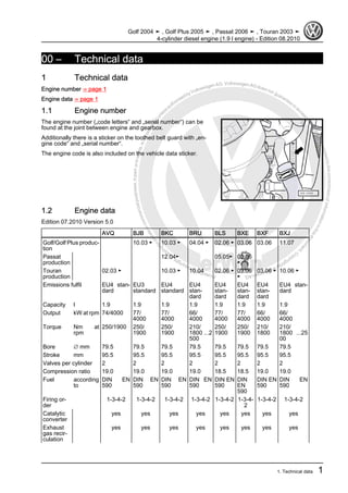
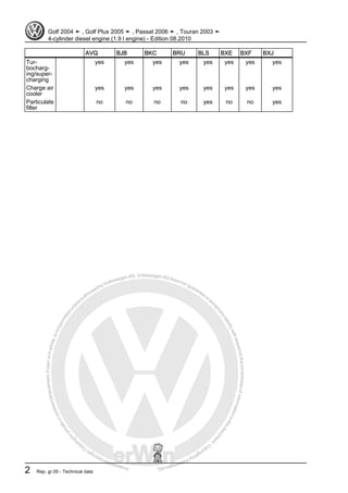
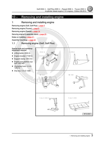
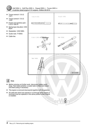
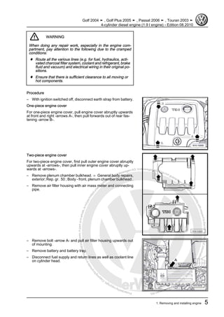
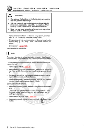
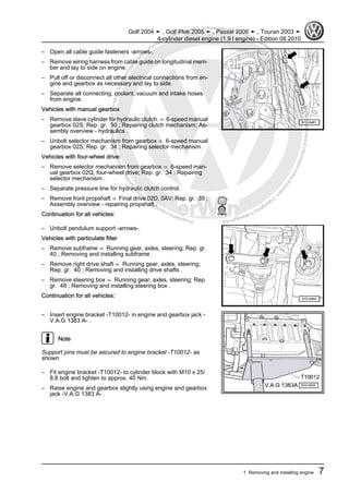
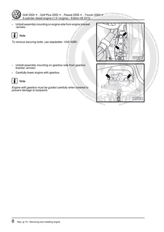
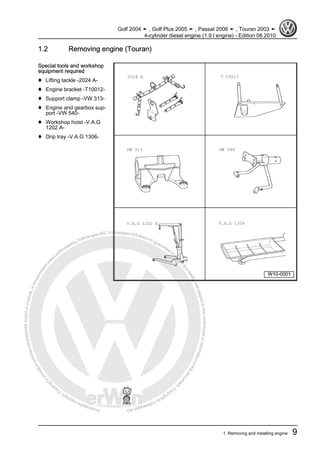
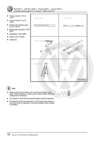
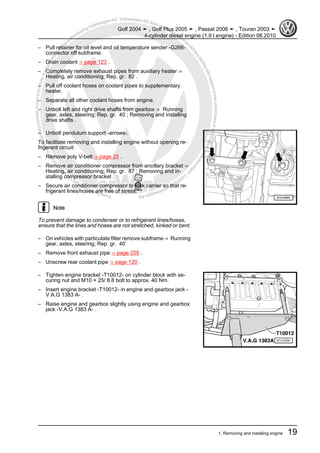
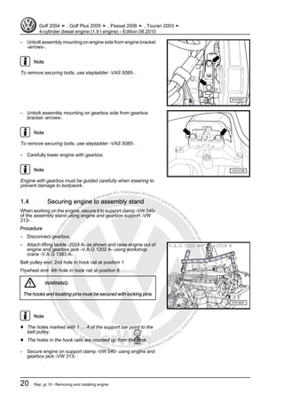
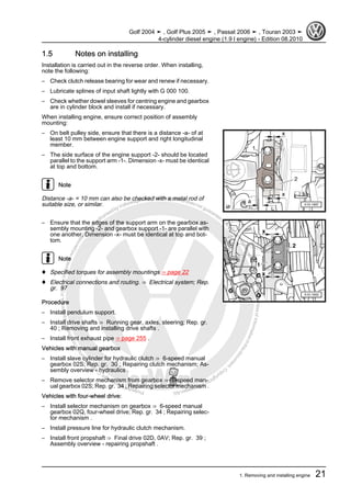
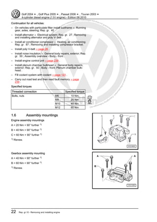
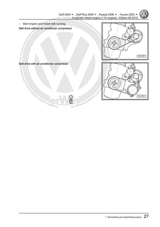
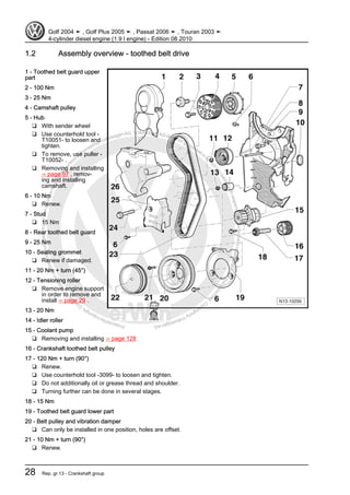
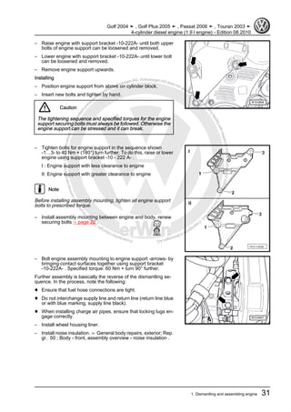
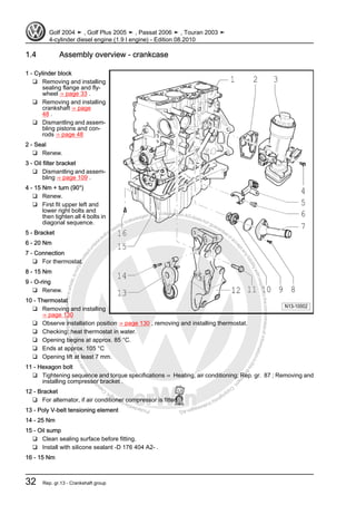
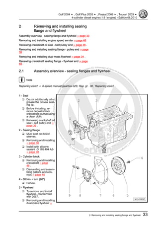
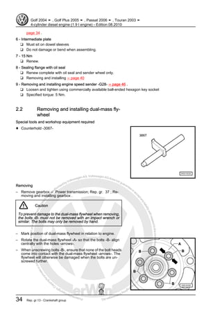
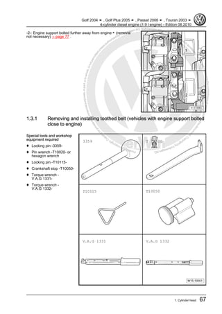
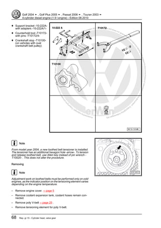
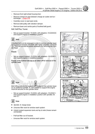
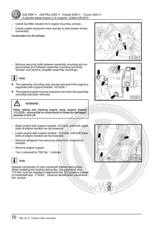
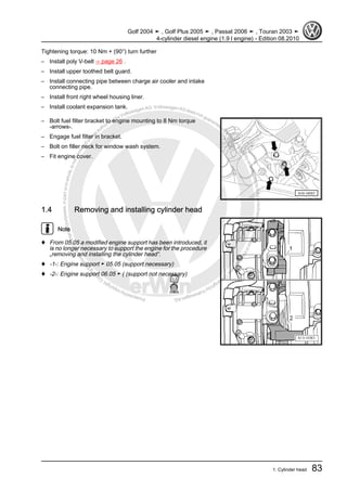
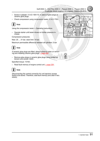
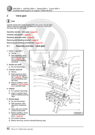
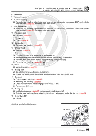
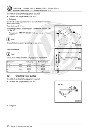
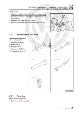
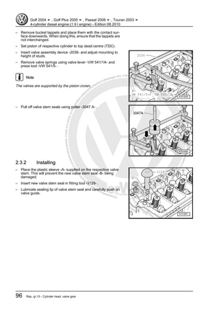
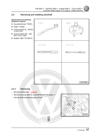
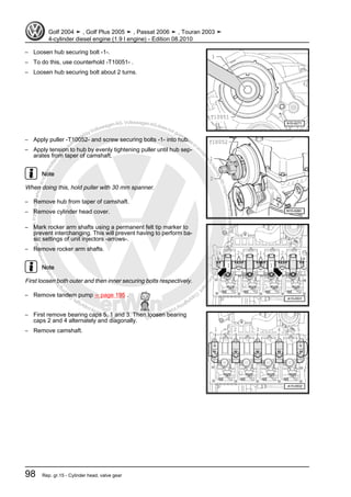
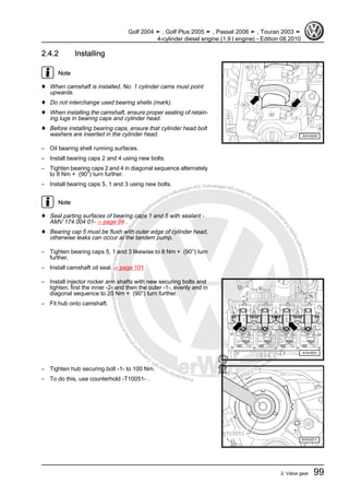
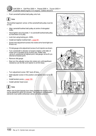
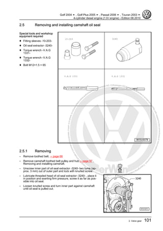
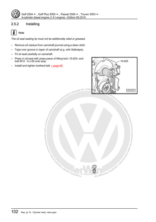
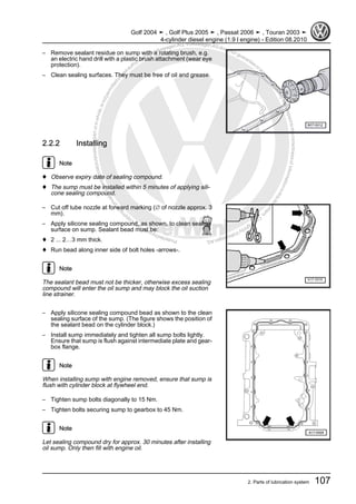
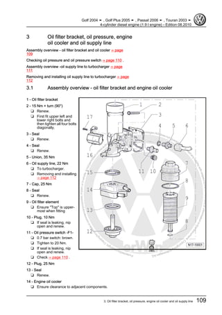
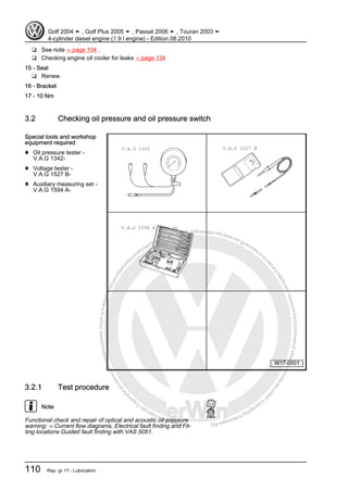
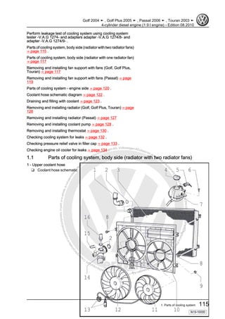
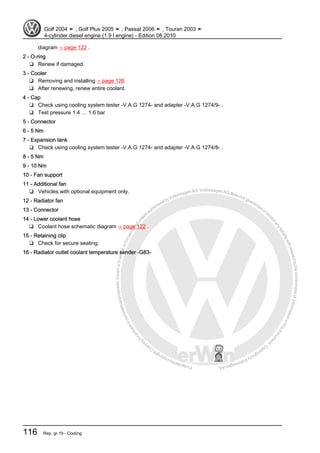
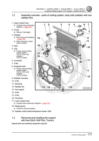
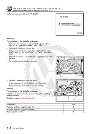
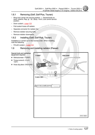
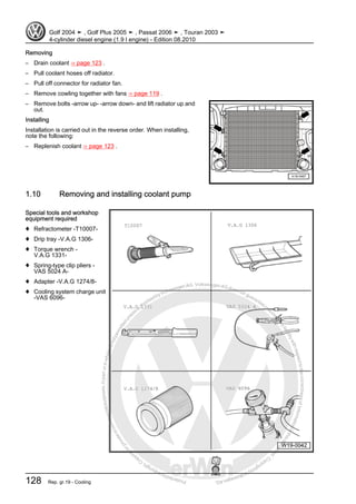
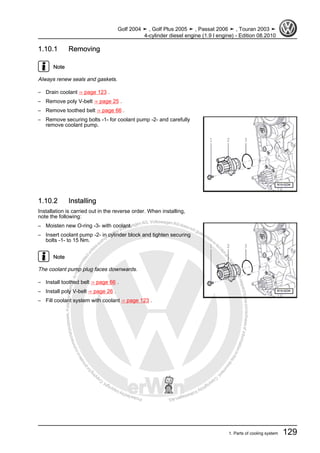
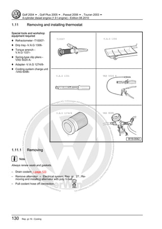
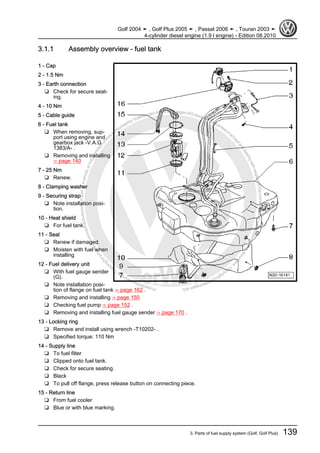
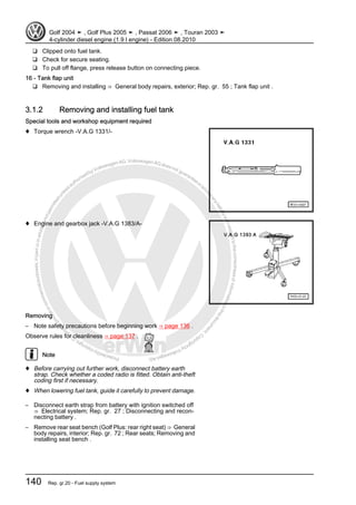
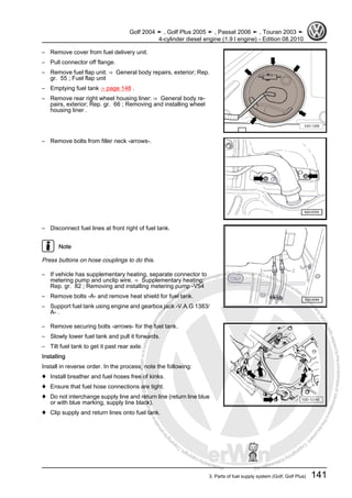
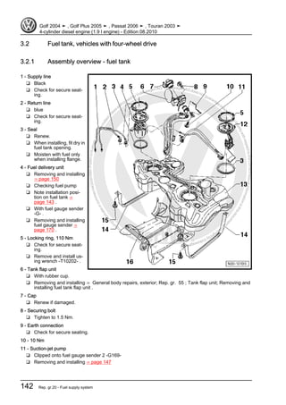
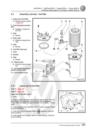
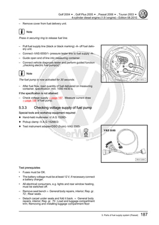
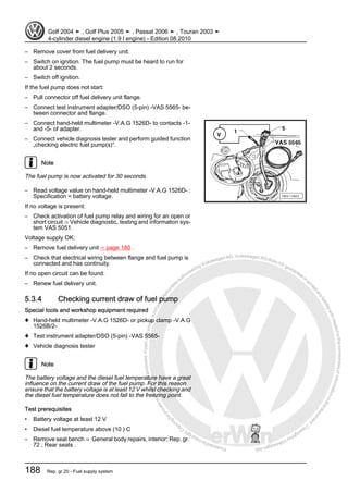
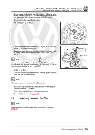
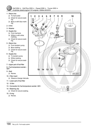
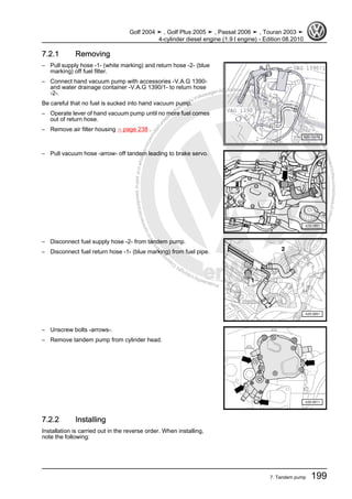
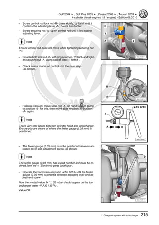
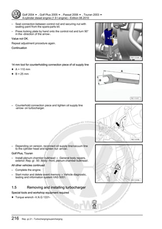
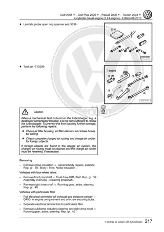
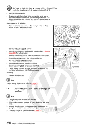
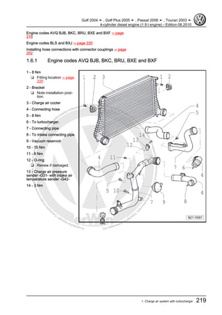
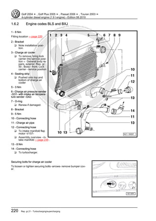
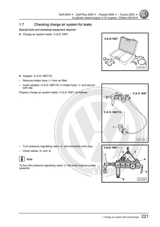
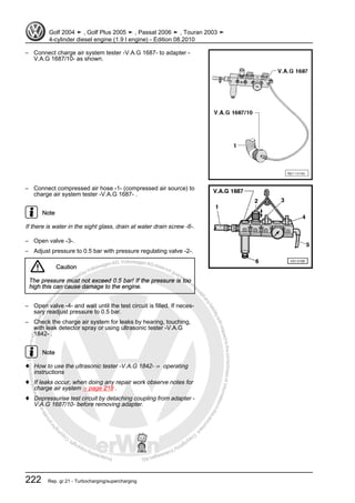
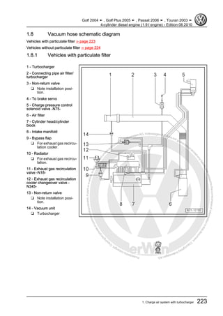
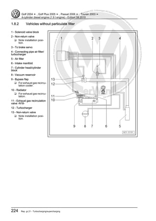
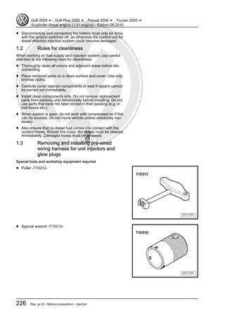
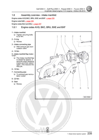
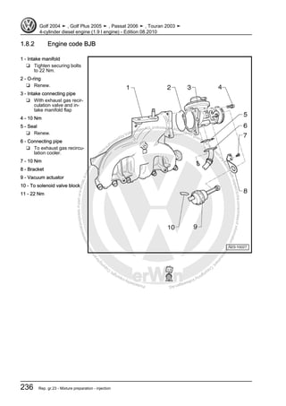
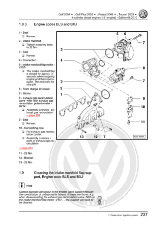
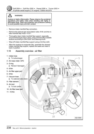
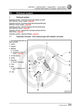
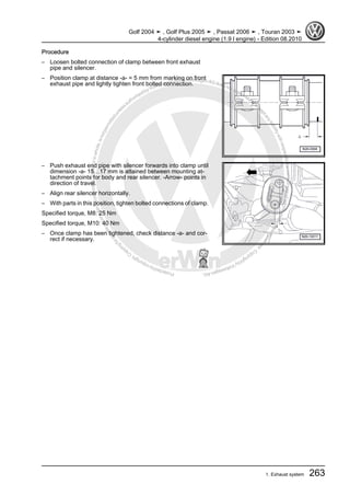
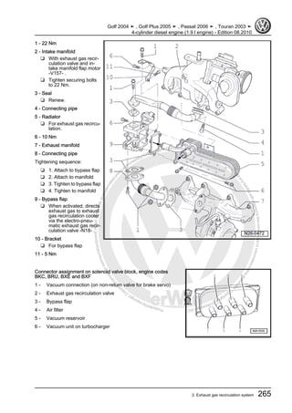
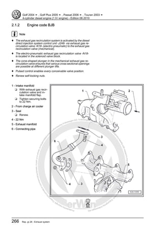
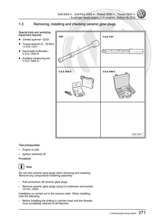
Protectedbycopyright.Copyi
ngforprivateorcommercialpurposes,inpartorinwhole,isnotpermittedunle
ssauthorisedbyVolkswagenAG.VolkswagenAGdoesnot guaranteeorac
ceptanyliabilitywithrespecttothecorrectnessofinformationinthisdocum
en
t.CopyrightbyVolkswagenAG.
Workshop Manual
Golf 2004 ➤
Golf Plus 2005 ➤
Passat 2006 ➤
Touran 2003 ➤
4-cylinder diesel engine (1.9 l engine)
Engine ID AVQ BJB BKC BLS BRU BXE BXF BXJ
Edition 08.2010
Service
Service Department. Technical Information
Protectedbycopyright.Copyi
ngforprivateorcommercialpurposes,inpartorinwhole,isnotpermittedunle
ssauthorisedbyVolkswagenAG.VolkswagenAGdoesnot guaranteeorac
ceptanyliabilitywithrespecttothecorrectnessofinformationinthisdocum
en
t.CopyrightbyVolkswagenAG.
List of Workshop Manual Repair GroupsList of Workshop Manual
Repair GroupsList of Workshop Manual Repair Groups
Repair Group
00 - Technical data
10 - Removing and installing engine
13 - Crankshaft group
15 - Cylinder head, valve gear
17 - Lubrication
19 - Cooling
20 - Fuel supply system
21 - Turbocharging/supercharging
23 - Mixture preparation - injection
26 - Exhaust system
28 - Glow plug system
Technical information should always be available to the foremen and mechanics, because their
careful and constant adherence to the instructions is essential to ensure vehicle road-worthiness and
safety. In addition, the normal basic safety precautions for working on motor vehicles must, as a
matter of course, be observed.
Service
All rights reserved.
No reproduction without prior agreement from publisher.
Copyright © 2010 Volkswagen AG, Wolfsburg D3E801CBF41
Protectedbycopyright.Copyi
ngforprivateorcommercialpurposes,inpartorinwhole,isnotpermittedunle
ssauthorisedbyVolkswagenAG.VolkswagenAGdoesnot guaranteeorac
ceptanyliabilitywithrespecttothecorrectnessofinformationinthisdocum
en
t.CopyrightbyVolkswagenAG.
Contents
00 - Technical data . . . . . . . . . . . . . . . . . . . . . . . . . . . . . . . . . . . . . . . . . . . . . . . . . . . . 1
1 Technical data . . . . . . . . . . . . . . . . . . . . . . . . . . . . . . . . . . . . . . . . . . . . . . . . . . . . . . . . . . 1
1.1 Engine number . . . . . . . . . . . . . . . . . . . . . . . . . . . . . . . . . . . . . . . . . . . . . . . . . . . . . . . . . . 1
1.2 Engine data . . . . . . . . . . . . . . . . . . . . . . . . . . . . . . . . . . . . . . . . . . . . . . . . . . . . . . . . . . . . 1
10 - Removing and installing engine . . . . . . . . . . . . . . . . . . . . . . . . . . . . . . . . . . . . . . 3
1 Removing and installing engine . . . . . . . . . . . . . . . . . . . . . . . . . . . . . . . . . . . . . . . . . . . . . . 3
1.1 Removing engine (Golf, Golf Plus) . . . . . . . . . . . . . . . . . . . . . . . . . . . . . . . . . . . . . . . . . . . . 3
1.2 Removing engine (Touran) . . . . . . . . . . . . . . . . . . . . . . . . . . . . . . . . . . . . . . . . . . . . . . . . . . 9
1.3 Removing engine (Passat) . . . . . . . . . . . . . . . . . . . . . . . . . . . . . . . . . . . . . . . . . . . . . . . . . . 14
1.4 Securing engine to assembly stand . . . . . . . . . . . . . . . . . . . . . . . . . . . . . . . . . . . . . . . . . . 20
1.5 Notes on installing . . . . . . . . . . . . . . . . . . . . . . . . . . . . . . . . . . . . . . . . . . . . . . . . . . . . . . . . 21
1.6 Assembly mountings . . . . . . . . . . . . . . . . . . . . . . . . . . . . . . . . . . . . . . . . . . . . . . . . . . . . . . 22
13 - Crankshaft group . . . . . . . . . . . . . . . . . . . . . . . . . . . . . . . . . . . . . . . . . . . . . . . . . . 24
1 Dismantling and assembling engine . . . . . . . . . . . . . . . . . . . . . . . . . . . . . . . . . . . . . . . . . . 24
1.1 Assembly overview - poly V-belt drive . . . . . . . . . . . . . . . . . . . . . . . . . . . . . . . . . . . . . . . . 24
1.2 Assembly overview - toothed belt drive . . . . . . . . . . . . . . . . . . . . . . . . . . . . . . . . . . . . . . . . 28
1.3 Removing and installing engine support . . . . . . . . . . . . . . . . . . . . . . . . . . . . . . . . . . . . . . 29
1.4 Assembly overview - crankcase . . . . . . . . . . . . . . . . . . . . . . . . . . . . . . . . . . . . . . . . . . . . . . 32
2 Removing and installing sealing flange and flywheel . . . . . . . . . . . . . . . . . . . . . . . . . . . . . . 33
2.1 Assembly overview - sealing flanges and flywheel . . . . . . . . . . . . . . . . . . . . . . . . . . . . . . 33
2.2 Removing and installing dual-mass flywheel . . . . . . . . . . . . . . . . . . . . . . . . . . . . . . . . . . . . 34
2.3 Renewing crankshaft oil seal - belt pulley end . . . . . . . . . . . . . . . . . . . . . . . . . . . . . . . . . . 36
2.4 Removing and installing sealing flange - pulley end . . . . . . . . . . . . . . . . . . . . . . . . . . . . . . 38
2.5 Renewing crankshaft sealing flange - flywheel end . . . . . . . . . . . . . . . . . . . . . . . . . . . . . . 40
2.6 Removing and installing engine speed sender G28 . . . . . . . . . . . . . . . . . . . . . . . . . . . . . . 46
3 Crankshaft . . . . . . . . . . . . . . . . . . . . . . . . . . . . . . . . . . . . . . . . . . . . . . . . . . . . . . . . . . . . . . 48
3.1 Assembly overview - crankshaft . . . . . . . . . . . . . . . . . . . . . . . . . . . . . . . . . . . . . . . . . . . . . . 48
4 Pistons and conrods . . . . . . . . . . . . . . . . . . . . . . . . . . . . . . . . . . . . . . . . . . . . . . . . . . . . . . 54
4.1 Assembly overview - pistons and conrods . . . . . . . . . . . . . . . . . . . . . . . . . . . . . . . . . . . . . . 54
4.2 Separating new conrod . . . . . . . . . . . . . . . . . . . . . . . . . . . . . . . . . . . . . . . . . . . . . . . . . . . . 55
4.3 Checking piston projection at TDC . . . . . . . . . . . . . . . . . . . . . . . . . . . . . . . . . . . . . . . . . . . . 56
4.4 Piston and cylinder dimensions . . . . . . . . . . . . . . . . . . . . . . . . . . . . . . . . . . . . . . . . . . . . . . 57
4.5 Piston rings, cylinder bore and piston installation position . . . . . . . . . . . . . . . . . . . . . . . . . . 57
15 - Cylinder head, valve gear . . . . . . . . . . . . . . . . . . . . . . . . . . . . . . . . . . . . . . . . . . 60
1 Cylinder head . . . . . . . . . . . . . . . . . . . . . . . . . . . . . . . . . . . . . . . . . . . . . . . . . . . . . . . . . . . . 60
1.1 Assembly overview - cylinder head . . . . . . . . . . . . . . . . . . . . . . . . . . . . . . . . . . . . . . . . . . 61
1.2 Removing and installing cylinder head cover . . . . . . . . . . . . . . . . . . . . . . . . . . . . . . . . . . . . 64
1.3 Removing, installing and tensioning toothed belts . . . . . . . . . . . . . . . . . . . . . . . . . . . . . . . . 66
1.4 Removing and installing cylinder head . . . . . . . . . . . . . . . . . . . . . . . . . . . . . . . . . . . . . . . . 83
1.5 Checking compression . . . . . . . . . . . . . . . . . . . . . . . . . . . . . . . . . . . . . . . . . . . . . . . . . . . . 89
2 Valve gear . . . . . . . . . . . . . . . . . . . . . . . . . . . . . . . . . . . . . . . . . . . . . . . . . . . . . . . . . . . . . . 92
2.1 Assembly overview - valve gear . . . . . . . . . . . . . . . . . . . . . . . . . . . . . . . . . . . . . . . . . . . . . . 92
2.2 Checking valve guides . . . . . . . . . . . . . . . . . . . . . . . . . . . . . . . . . . . . . . . . . . . . . . . . . . . . 94
2.3 Renewing valve stem seals . . . . . . . . . . . . . . . . . . . . . . . . . . . . . . . . . . . . . . . . . . . . . . . . 95
2.4 Removing and installing camshaft . . . . . . . . . . . . . . . . . . . . . . . . . . . . . . . . . . . . . . . . . . . . 97
2.5 Removing and installing camshaft oil seal . . . . . . . . . . . . . . . . . . . . . . . . . . . . . . . . . . . . . . 101
17 - Lubrication . . . . . . . . . . . . . . . . . . . . . . . . . . . . . . . . . . . . . . . . . . . . . . . . . . . . . . 103
1 Engine oil . . . . . . . . . . . . . . . . . . . . . . . . . . . . . . . . . . . . . . . . . . . . . . . . . . . . . . . . . . . . . . 103
Golf 2004 ➤ , Golf Plus 2005 ➤ , Passat 2006 ➤ , Touran 2003 ➤
4-cylinder diesel engine (1.9 l engine) - Edition 08.2010
Contents i
Protectedbycopyright.Copyi
ngforprivateorcommercialpurposes,inpartorinwhole,isnotpermittedunle
ssauthorisedbyVolkswagenAG.VolkswagenAGdoesnot guaranteeorac
ceptanyliabilitywithrespecttothecorrectnessofinformationinthisdocum
en
t.CopyrightbyVolkswagenAG.
1.1 Oil capacities . . . . . . . . . . . . . . . . . . . . . . . . . . . . . . . . . . . . . . . . . . . . . . . . . . . . . . . . . . . . 103
1.2 Checking engine oil level . . . . . . . . . . . . . . . . . . . . . . . . . . . . . . . . . . . . . . . . . . . . . . . . . . 103
1.3 Checking engine oil level . . . . . . . . . . . . . . . . . . . . . . . . . . . . . . . . . . . . . . . . . . . . . . . . . . 103
2 Parts of lubrication system . . . . . . . . . . . . . . . . . . . . . . . . . . . . . . . . . . . . . . . . . . . . . . . . . . 104
2.1 Assembly overview - oil pump, sump . . . . . . . . . . . . . . . . . . . . . . . . . . . . . . . . . . . . . . . . . . 104
2.2 Removing and installing oil sump . . . . . . . . . . . . . . . . . . . . . . . . . . . . . . . . . . . . . . . . . . . . 105
3 Oil filter bracket, oil pressure, engine oil cooler and oil supply line . . . . . . . . . . . . . . . . . . 109
3.1 Assembly overview - oil filter bracket and engine oil cooler . . . . . . . . . . . . . . . . . . . . . . . . 109
3.2 Checking oil pressure and oil pressure switch . . . . . . . . . . . . . . . . . . . . . . . . . . . . . . . . . . 110
3.3 Assembly overview - oil supply line to turbocharger . . . . . . . . . . . . . . . . . . . . . . . . . . . . . . 111
3.4 Removing and installing oil supply line to turbocharger . . . . . . . . . . . . . . . . . . . . . . . . . . . . 112
19 - Cooling . . . . . . . . . . . . . . . . . . . . . . . . . . . . . . . . . . . . . . . . . . . . . . . . . . . . . . . . . . 114
1 Parts of cooling system . . . . . . . . . . . . . . . . . . . . . . . . . . . . . . . . . . . . . . . . . . . . . . . . . . . . 114
1.1 Parts of cooling system, body side (radiator with two radiator fans) . . . . . . . . . . . . . . . . . . 115
1.2 Assembly overview - parts of cooling system, body side (radiator with one radiator fan) . . 117
1.3 Removing and installing fan support with fans (Golf, Golf Plus, Touran) . . . . . . . . . . . . . . 117
1.4 Removing and installing fan support with fans (Passat) . . . . . . . . . . . . . . . . . . . . . . . . . . . . 119
1.5 Parts of cooling system, engine side . . . . . . . . . . . . . . . . . . . . . . . . . . . . . . . . . . . . . . . . . . 120
1.6 Coolant hose schematic diagram . . . . . . . . . . . . . . . . . . . . . . . . . . . . . . . . . . . . . . . . . . . . 122
1.7 Draining and filling coolant . . . . . . . . . . . . . . . . . . . . . . . . . . . . . . . . . . . . . . . . . . . . . . . . . . 123
1.8 Removing and installing radiator (Golf, Golf Plus, Touran) . . . . . . . . . . . . . . . . . . . . . . . . 126
1.9 Removing and installing radiator (Passat) . . . . . . . . . . . . . . . . . . . . . . . . . . . . . . . . . . . . . . 127
1.10 Removing and installing coolant pump . . . . . . . . . . . . . . . . . . . . . . . . . . . . . . . . . . . . . . . . 128
1.11 Removing and installing thermostat . . . . . . . . . . . . . . . . . . . . . . . . . . . . . . . . . . . . . . . . . . 130
1.12 Checking cooling system for leaks . . . . . . . . . . . . . . . . . . . . . . . . . . . . . . . . . . . . . . . . . . . . 132
1.13 Checking engine oil cooler for leaks . . . . . . . . . . . . . . . . . . . . . . . . . . . . . . . . . . . . . . . . . . 134
20 - Fuel supply system . . . . . . . . . . . . . . . . . . . . . . . . . . . . . . . . . . . . . . . . . . . . . . . . 136
1 Safety precautions . . . . . . . . . . . . . . . . . . . . . . . . . . . . . . . . . . . . . . . . . . . . . . . . . . . . . . . . 136
1.1 Safety precautions when working on fuel supply system . . . . . . . . . . . . . . . . . . . . . . . . . . 136
2 Rules for cleanliness . . . . . . . . . . . . . . . . . . . . . . . . . . . . . . . . . . . . . . . . . . . . . . . . . . . . . . 137
2.1 Rules for cleanliness when working on fuel supply system . . . . . . . . . . . . . . . . . . . . . . . . 137
3 Parts of fuel supply system (Golf, Golf Plus) . . . . . . . . . . . . . . . . . . . . . . . . . . . . . . . . . . . . 138
3.1 Fuel tank, vehicles with front-wheel drive . . . . . . . . . . . . . . . . . . . . . . . . . . . . . . . . . . . . . . 138
3.2 Fuel tank, vehicles with four-wheel drive . . . . . . . . . . . . . . . . . . . . . . . . . . . . . . . . . . . . . . 142
3.3 Emptying fuel tank . . . . . . . . . . . . . . . . . . . . . . . . . . . . . . . . . . . . . . . . . . . . . . . . . . . . . . . . 148
3.4 Removing and installing fuel delivery unit . . . . . . . . . . . . . . . . . . . . . . . . . . . . . . . . . . . . . . 150
3.5 Removing and installing fuel gauge sender . . . . . . . . . . . . . . . . . . . . . . . . . . . . . . . . . . . . 151
3.6 Checking fuel pump . . . . . . . . . . . . . . . . . . . . . . . . . . . . . . . . . . . . . . . . . . . . . . . . . . . . . . 152
3.7 Assembly overview - fuel filter . . . . . . . . . . . . . . . . . . . . . . . . . . . . . . . . . . . . . . . . . . . . . . 156
3.8 Removing and installing fuel cooler . . . . . . . . . . . . . . . . . . . . . . . . . . . . . . . . . . . . . . . . . . 158
4 Parts of fuel supply system (Touran) . . . . . . . . . . . . . . . . . . . . . . . . . . . . . . . . . . . . . . . . . . 160
4.1 Assembly overview - fuel tank with attachments . . . . . . . . . . . . . . . . . . . . . . . . . . . . . . . . 161
4.2 Emptying fuel tank . . . . . . . . . . . . . . . . . . . . . . . . . . . . . . . . . . . . . . . . . . . . . . . . . . . . . . . . 162
4.3 Removing and installing fuel tank . . . . . . . . . . . . . . . . . . . . . . . . . . . . . . . . . . . . . . . . . . . . 165
4.4 Assembly overview - fuel filter . . . . . . . . . . . . . . . . . . . . . . . . . . . . . . . . . . . . . . . . . . . . . . 167
4.5 Removing and installing fuel cooler . . . . . . . . . . . . . . . . . . . . . . . . . . . . . . . . . . . . . . . . . . 168
4.6 Removing and installing fuel delivery unit . . . . . . . . . . . . . . . . . . . . . . . . . . . . . . . . . . . . . . 169
4.7 Removing and installing fuel gauge sender . . . . . . . . . . . . . . . . . . . . . . . . . . . . . . . . . . . . 170
4.8 Checking fuel pump . . . . . . . . . . . . . . . . . . . . . . . . . . . . . . . . . . . . . . . . . . . . . . . . . . . . . . 171
5 Parts of fuel supply system (Passat) . . . . . . . . . . . . . . . . . . . . . . . . . . . . . . . . . . . . . . . . . . 176
5.1 Fuel tank, vehicles with front-wheel drive . . . . . . . . . . . . . . . . . . . . . . . . . . . . . . . . . . . . . . 176
5.2 Emptying fuel tank, vehicles with front-wheel drive . . . . . . . . . . . . . . . . . . . . . . . . . . . . . . 183
5.3 Checking fuel pump . . . . . . . . . . . . . . . . . . . . . . . . . . . . . . . . . . . . . . . . . . . . . . . . . . . . . . 185
Golf 2004 ➤ , Golf Plus 2005 ➤ , Passat 2006 ➤ , Touran 2003 ➤
4-cylinder diesel engine (1.9 l engine) - Edition 08.2010
ii Contents
Protectedbycopyright.Copyi
ngforprivateorcommercialpurposes,inpartorinwhole,isnotpermittedunle
ssauthorisedbyVolkswagenAG.VolkswagenAGdoesnot guaranteeorac
ceptanyliabilitywithrespecttothecorrectnessofinformationinthisdocum
en
t.CopyrightbyVolkswagenAG.
5.4 Assembly overview - fuel filter . . . . . . . . . . . . . . . . . . . . . . . . . . . . . . . . . . . . . . . . . . . . . . 189
5.5 Removing and installing fuel cooler . . . . . . . . . . . . . . . . . . . . . . . . . . . . . . . . . . . . . . . . . . 191
6 Accelerator mechanism . . . . . . . . . . . . . . . . . . . . . . . . . . . . . . . . . . . . . . . . . . . . . . . . . . . . 193
6.1 Assembly overview - accelerator mechanism . . . . . . . . . . . . . . . . . . . . . . . . . . . . . . . . . . 193
7 Tandem pump . . . . . . . . . . . . . . . . . . . . . . . . . . . . . . . . . . . . . . . . . . . . . . . . . . . . . . . . . . 195
7.1 Checking tandem pump . . . . . . . . . . . . . . . . . . . . . . . . . . . . . . . . . . . . . . . . . . . . . . . . . . . . 195
7.2 Removing and installing tandem pump . . . . . . . . . . . . . . . . . . . . . . . . . . . . . . . . . . . . . . . . 198
21 - Turbocharging/supercharging . . . . . . . . . . . . . . . . . . . . . . . . . . . . . . . . . . . . . . . . 201
1 Charge air system with turbocharger . . . . . . . . . . . . . . . . . . . . . . . . . . . . . . . . . . . . . . . . . . 201
1.1 Safety precautions . . . . . . . . . . . . . . . . . . . . . . . . . . . . . . . . . . . . . . . . . . . . . . . . . . . . . . . . 201
1.2 Rules for cleanliness . . . . . . . . . . . . . . . . . . . . . . . . . . . . . . . . . . . . . . . . . . . . . . . . . . . . . . 201
1.3 Hose connections . . . . . . . . . . . . . . . . . . . . . . . . . . . . . . . . . . . . . . . . . . . . . . . . . . . . . . . . 202
1.4 Assembly overview - turbocharger . . . . . . . . . . . . . . . . . . . . . . . . . . . . . . . . . . . . . . . . . . . . 203
1.5 Removing and installing turbocharger . . . . . . . . . . . . . . . . . . . . . . . . . . . . . . . . . . . . . . . . 216
1.6 Assembly overview - parts of charge air cooling . . . . . . . . . . . . . . . . . . . . . . . . . . . . . . . . 218
1.7 Checking charge air system for leaks . . . . . . . . . . . . . . . . . . . . . . . . . . . . . . . . . . . . . . . . 221
1.8 Vacuum hose schematic diagram . . . . . . . . . . . . . . . . . . . . . . . . . . . . . . . . . . . . . . . . . . . . 223
23 - Mixture preparation - injection . . . . . . . . . . . . . . . . . . . . . . . . . . . . . . . . . . . . . . . . 225
1 Diesel direct injection system . . . . . . . . . . . . . . . . . . . . . . . . . . . . . . . . . . . . . . . . . . . . . . . . 225
1.1 Safety precautions . . . . . . . . . . . . . . . . . . . . . . . . . . . . . . . . . . . . . . . . . . . . . . . . . . . . . . . . 225
1.2 Rules for cleanliness . . . . . . . . . . . . . . . . . . . . . . . . . . . . . . . . . . . . . . . . . . . . . . . . . . . . . . 226
1.3 Removing and installing pre-wired wiring harness for unit injectors and glow plugs . . . . . . 226
1.4 Assembly overview - unit injector . . . . . . . . . . . . . . . . . . . . . . . . . . . . . . . . . . . . . . . . . . . . 229
1.5 Removing and installing unit injector . . . . . . . . . . . . . . . . . . . . . . . . . . . . . . . . . . . . . . . . . . 230
1.6 Adjusting non-contact gap of unit injectors . . . . . . . . . . . . . . . . . . . . . . . . . . . . . . . . . . . . . . 232
1.7 Removing and installing O-rings for unit injector . . . . . . . . . . . . . . . . . . . . . . . . . . . . . . . . 233
1.8 Assembly overview - intake manifold . . . . . . . . . . . . . . . . . . . . . . . . . . . . . . . . . . . . . . . . . . 235
1.9 Cleaning the intake manifold flap support, Engine code BLS and BXJ . . . . . . . . . . . . . . . . 237
1.10 Assembly overview - air filter . . . . . . . . . . . . . . . . . . . . . . . . . . . . . . . . . . . . . . . . . . . . . . . . 238
2 Engine control unit . . . . . . . . . . . . . . . . . . . . . . . . . . . . . . . . . . . . . . . . . . . . . . . . . . . . . . . . 239
2.1 Reading and clearing engine control unit fault memory . . . . . . . . . . . . . . . . . . . . . . . . . . . . 239
2.2 Adapting functions and components . . . . . . . . . . . . . . . . . . . . . . . . . . . . . . . . . . . . . . . . . . 240
2.3 Removing and installing engine control unit (Golf) . . . . . . . . . . . . . . . . . . . . . . . . . . . . . . . . 240
2.4 Removing and installing anti-theft engine control unit (Golf) . . . . . . . . . . . . . . . . . . . . . . . . 241
2.5 Removing and installing engine control unit (Golf Plus) . . . . . . . . . . . . . . . . . . . . . . . . . . . . 243
2.6 Removing and installing anti-theft engine control unit (Golf Plus) . . . . . . . . . . . . . . . . . . . . 244
2.7 Removing and installing engine control unit (Touran) . . . . . . . . . . . . . . . . . . . . . . . . . . . . 246
2.8 Removing and installing anti-theft engine control unit (Touran) . . . . . . . . . . . . . . . . . . . . . . 247
3 Engine control unit (Passat) . . . . . . . . . . . . . . . . . . . . . . . . . . . . . . . . . . . . . . . . . . . . . . . . 250
3.1 Removing and installing engine control unit . . . . . . . . . . . . . . . . . . . . . . . . . . . . . . . . . . . . 250
3.2 Removing and installing anti-theft engine control unit . . . . . . . . . . . . . . . . . . . . . . . . . . . . 251
26 - Exhaust system . . . . . . . . . . . . . . . . . . . . . . . . . . . . . . . . . . . . . . . . . . . . . . . . . . 255
1 Exhaust system . . . . . . . . . . . . . . . . . . . . . . . . . . . . . . . . . . . . . . . . . . . . . . . . . . . . . . . . . . 255
1.1 Assembly overview - front exhaust pipe with catalytic converter . . . . . . . . . . . . . . . . . . . . 255
1.2 Assembly overview - front exhaust pipe with particulate filter . . . . . . . . . . . . . . . . . . . . . . 256
1.3 Assembly overview - silencer with mountings (vehicles with front wheel drive) . . . . . . . . . . 258
1.4 Assembly overview - silencers (Passat) . . . . . . . . . . . . . . . . . . . . . . . . . . . . . . . . . . . . . . . . 261
1.5 Assembly overview - silencer with mountings (vehicles with four-wheel drive) . . . . . . . . . . 262
1.6 Aligning exhaust system free of stress . . . . . . . . . . . . . . . . . . . . . . . . . . . . . . . . . . . . . . . . 262
2 Exhaust gas recirculation system . . . . . . . . . . . . . . . . . . . . . . . . . . . . . . . . . . . . . . . . . . . . 264
2.1 Assembly overview - parts of exhaust gas recirculation . . . . . . . . . . . . . . . . . . . . . . . . . . . . 264
2.2 Checking mechanical exhaust gas recirculation valve . . . . . . . . . . . . . . . . . . . . . . . . . . . . 268
Golf 2004 ➤ , Golf Plus 2005 ➤ , Passat 2006 ➤ , Touran 2003 ➤
4-cylinder diesel engine (1.9 l engine) - Edition 08.2010
Contents iii
Protectedbycopyright.Copyi
ngforprivateorcommercialpurposes,inpartorinwhole,isnotpermittedunle
ssauthorisedbyVolkswagenAG.VolkswagenAGdoesnot guaranteeorac
ceptanyliabilitywithrespecttothecorrectnessofinformationinthisdocum
en
t.CopyrightbyVolkswagenAG.
28 - Glow plug system . . . . . . . . . . . . . . . . . . . . . . . . . . . . . . . . . . . . . . . . . . . . . . . . 269
1 Checking glow plug system . . . . . . . . . . . . . . . . . . . . . . . . . . . . . . . . . . . . . . . . . . . . . . . . 269
1.1 Removing, installing and checking glow plugs . . . . . . . . . . . . . . . . . . . . . . . . . . . . . . . . . . 269
1.2 Characteristics of ceramic glow plugs . . . . . . . . . . . . . . . . . . . . . . . . . . . . . . . . . . . . . . . . 270
1.3 Removing, installing and checking ceramic glow plugs . . . . . . . . . . . . . . . . . . . . . . . . . . . . 271
Golf 2004 ➤ , Golf Plus 2005 ➤ , Passat 2006 ➤ , Touran 2003 ➤
4-cylinder diesel engine (1.9 l engine) - Edition 08.2010
iv Contents
Protectedbycopyright.Copyi
ngforprivateorcommercialpurposes,inpartorinwhole,isnotpermittedunle
ssauthorisedbyVolkswagenAG.VolkswagenAGdoesnot guaranteeorac
ceptanyliabilitywithrespecttothecorrectnessofinformationinthisdocum
en
t.CopyrightbyVolkswagenAG.
00 – Technical data
1 Technical data
Engine number ⇒ page 1
Engine data ⇒ page 1
1.1 Engine number
The engine number („code letters“ and „serial number“) can be
found at the joint between engine and gearbox.
Additionally there is a sticker on the toothed belt guard with „en‐
gine code“ and „serial number“.
The engine code is also included on the vehicle data sticker.
1.2 Engine data
Edition 07.2010 Version 5.0
AVQ BJB BKC BRU BLS BXE BXF BXJ
Golf/Golf Plus produc‐
tion
10.03 ► 10.03 ► 04.04 ► 02.06 ► 03.06 03.06 11.07
Passat
production
12.04► 05.05► 03.06
►
Touran
production
02.03 ► 10.03 ► 10.04 02.06 ► 03.06
►
03.06 ► 10.06 ►
Emissions fulfil EU4 stan‐
dard
EU3
standard
EU4
standard
EU4
stan‐
dard
EU4
stan‐
dard
EU4
stan‐
dard
EU4
stan‐
dard
EU4 stan‐
dard
Capacity l 1.9 1.9 1.9 1.9 1.9 1.9 1.9 1.9
Output kW at rpm 74/4000 77/
4000
77/
4000
66/
4000
77/
4000
77/
4000
66/
4000
66/
4000
Torque Nm at
rpm
250/1900 250/
1900
250/
1900
210/
1800 ...2
500
250/
1900
250/
1900
210/
1800
210/
1800 ...25
00
Bore ∅ mm 79.5 79.5 79.5 79.5 79.5 79.5 79.5 79.5
Stroke mm 95.5 95.5 95.5 95.5 95.5 95.5 95.5 95.5
Valves per cylinder 2 2 2 2 2 2 2 2
Compression ratio 19.0 19.0 19.0 19.0 18.5 18.5 19.0 19.0
Fuel according
to
DIN EN
590
DIN EN
590
DIN EN
590
DIN EN
590
DIN EN
590
DIN
EN
590
DIN EN
590
DIN EN
590
Firing or‐
der
1-3-4-2 1-3-4-2 1-3-4-2 1-3-4-2 1-3-4-2 1-3-4-
2
1-3-4-2 1-3-4-2
Catalytic
converter
yes yes yes yes yes yes yes yes
Exhaust
gas recir‐
culation
yes yes yes yes yes yes yes yes
Golf 2004 ➤ , Golf Plus 2005 ➤ , Passat 2006 ➤ , Touran 2003 ➤
4-cylinder diesel engine (1.9 l engine) - Edition 08.2010
1. Technical data 1
Protectedbycopyright.Copyi
ngforprivateorcommercialpurposes,inpartorinwhole,isnotpermittedunle
ssauthorisedbyVolkswagenAG.VolkswagenAGdoesnot guaranteeorac
ceptanyliabilitywithrespecttothecorrectnessofinformationinthisdocum
en
t.CopyrightbyVolkswagenAG.
AVQ BJB BKC BRU BLS BXE BXF BXJ
Tur‐
bocharg‐
ing/super‐
charging
yes yes yes yes yes yes yes yes
Charge air
cooler
yes yes yes yes yes yes yes yes
Particulate
filter
no no no no yes no no yes
Golf 2004 ➤ , Golf Plus 2005 ➤ , Passat 2006 ➤ , Touran 2003 ➤
4-cylinder diesel engine (1.9 l engine) - Edition 08.2010
2 Rep. gr.00 - Technical data
Protectedbycopyright.Copyi
ngforprivateorcommercialpurposes,inpartorinwhole,isnotpermittedunle
ssauthorisedbyVolkswagenAG.VolkswagenAGdoesnot guaranteeorac
ceptanyliabilitywithrespecttothecorrectnessofinformationinthisdocum
en
t.CopyrightbyVolkswagenAG.
10 – Removing and installing engine
1 Removing and installing engine
Removing engine (Golf, Golf Plus) ⇒ page 3
Removing engine (Touran) ⇒ page 9
Removing engine (Passat) ⇒ page 14
Securing engine to assembly stand ⇒ page 20 .
Notes on installing ⇒ page 21 .
Assembly mountings ⇒ page 22
1.1 Removing engine (Golf, Golf Plus)
Special tools and workshop
equipment required
♦ Lifting tackle -2024 A-
♦ Engine bracket -T10012-
♦ Support clamp -VW 313-
♦ Engine and gearbox sup‐
port -VW 540-
♦ Workshop hoist -V.A.G
1202 A-
♦ Drip tray -V.A.G 1306-
Golf 2004 ➤ , Golf Plus 2005 ➤ , Passat 2006 ➤ , Touran 2003 ➤
4-cylinder diesel engine (1.9 l engine) - Edition 08.2010
1. Removing and installing engine 3
Protectedbycopyright.Copyi
ngforprivateorcommercialpurposes,inpartorinwhole,isnotpermittedunle
ssauthorisedbyVolkswagenAG.VolkswagenAGdoesnot guaranteeorac
ceptanyliabilitywithrespecttothecorrectnessofinformationinthisdocum
en
t.CopyrightbyVolkswagenAG.
♦ Torque wrench -V.A.G
1331-
♦ Torque wrench -V.A.G
1332-
♦ Engine and gearbox jack -
V.A.G 1383 A-
♦ Spring-type clip pliers -VAS
5024-
♦ Stepladder -VAS 5085-
♦ Guide rods -T10093-
♦ Cable ties
Note
♦ Before carrying out further work, disconnect battery earth
strap. First check whether a coded radio is fitted and obtain
anti-theft coding if necessary.
♦ The engine is removed downwards together with the gearbox.
♦ All cable ties which are opened or cut through when engine is
removed must be replaced in the same position when engine
is installed.
Golf 2004 ➤ , Golf Plus 2005 ➤ , Passat 2006 ➤ , Touran 2003 ➤
4-cylinder diesel engine (1.9 l engine) - Edition 08.2010
4 Rep. gr.10 - Removing and installing engine
Protectedbycopyright.Copyi
ngforprivateorcommercialpurposes,inpartorinwhole,isnotpermittedunle
ssauthorisedbyVolkswagenAG.VolkswagenAGdoesnot guaranteeoracceptanyliabilitywithrespecttothecorrectnessofinformationinthisdocum
en
t.CopyrightbyVolkswagenAG.
WARNING
When doing any repair work, especially in the engine com‐
partment, pay attention to the following due to the cramped
conditions:
♦ Route all the various lines (e.g. for fuel, hydraulics, acti‐
vated charcoal filter system, coolant and refrigerant, brake
fluid and vacuum) and electrical wiring in their original po‐
sitions.
♦ Ensure that there is sufficient clearance to all moving or
hot components.
Procedure
– With ignition switched off, disconnect earth strap from battery.
One-piece engine cover
For one-piece engine cover, pull engine cover abruptly upwards
at front and right -arrows A-, then pull forwards out of rear fas‐
tening -arrow B-.
Two-piece engine cover
For two-piece engine cover, first pull outer engine cover abruptly
upwards at -arrows-, then pull inner engine cover abruptly up‐
wards at -arrows-.
– Remove plenum chamber bulkhead. ⇒ General body repairs,
exterior; Rep. gr. 50 ; Body - front, plenum chamber bulkhead .
– Remove air filter housing with air mass meter and connecting
pipe.
– Remove bolt -arrow A- and pull air filter housing upwards out
of mounting.
– Remove battery and battery tray.
– Disconnect fuel supply and return lines as well as coolant line
on cylinder head.
Golf 2004 ➤ , Golf Plus 2005 ➤ , Passat 2006 ➤ , Touran 2003 ➤
4-cylinder diesel engine (1.9 l engine) - Edition 08.2010
1. Removing and installing engine 5
Protectedbycopyright.Copyi
ngforprivateorcommercialpurposes,inpartorinwhole,isnotpermittedunle
ssauthorisedbyVolkswagenAG.VolkswagenAGdoesnot guaranteeorac
ceptanyliabilitywithrespecttothecorrectnessofinformationinthisdocum
en
t.CopyrightbyVolkswagenAG.
WARNING
♦ The fuel and the fuel lines in the fuel system can become
very hot (danger of scalding)!
♦ The fuel system is also under pressure! Before opening
the system, place cloths around the connections. Then
carefully loosen connection to release the pressure!
♦ Wear eye and hand protection when performing any type
of repair work on the fuel system!
– Remove noise insulation ⇒ General body repairs, exterior;
Rep. gr. 50 ; Assembly overview - Body - front .
– Bring lock carrier into service position ⇒ General body repairs,
exterior; Rep. gr. 50 ; Body - front; Lock carrier - service po‐
sition .
– Drain coolant ⇒ page 123 .
Vehicles with air conditioner
Note
To prevent damage to condenser or to refrigerant lines/hoses,
ensure that the lines and hoses are not stretched, kinked or bent.
To facilitate removing and installing engine without opening re‐
frigerant circuit:
– Remove poly V-belt ⇒ page 25 .
– Remove air conditioner compressor ⇒ Heating, air condition‐
ing; Rep. gr. 87 ; Removing and installing compressor brack‐
et .
– Secure air conditioner compressor to lock carrier so that re‐
frigerant lines/hoses are free of stress.
– Remove alternator ⇒ Electrical system; Rep. gr. 27 ; Remov‐
ing and installing alternator and poly V-belt .
Continuation for all vehicles
– Remove connecting pipes between charge air cooler and en‐
gine.
– Unbolt left and right-hand drive shafts from gearbox ⇒ Run‐
ning gear, axles, steering; Rep. gr. 40 ; Removing and in‐
stalling drive shaft .
– Remove front exhaust pipe ⇒ page 255 .
– Release connector from engine control unit, disconnect con‐
nector.
Golf 2004 ➤ , Golf Plus 2005 ➤ , Passat 2006 ➤ , Touran 2003 ➤
4-cylinder diesel engine (1.9 l engine) - Edition 08.2010
6 Rep. gr.10 - Removing and installing engine
Protectedbycopyright.Copyi
ngforprivateorcommercialpurposes,inpartorinwhole,isnotpermittedunle
ssauthorisedbyVolkswagenAG.VolkswagenAGdoesnot guaranteeorac
ceptanyliabilitywithrespecttothecorrectnessofinformationinthisdocum
en
t.CopyrightbyVolkswagenAG.
– Open all cable guide fasteners -arrows-.
– Remove wiring harness from cable guide on longitudinal mem‐
ber and lay to side on engine.
– Pull off or disconnect all other electrical connections from en‐
gine and gearbox as necessary and lay to side.
– Separate all connecting, coolant, vacuum and intake hoses
from engine.
Vehicles with manual gearbox
– Remove slave cylinder for hydraulic clutch. ⇒ 6-speed manual
gearbox 02S; Rep. gr. 30 ; Repairing clutch mechanism; As‐
sembly overview - hydraulics .
– Unbolt selector mechanism from gearbox ⇒ 6-speed manual
gearbox 02S; Rep. gr. 34 ; Repairing selector mechanism .
Vehicles with four-wheel drive:
– Remove selector mechanism from gearbox ⇒ 6-speed man‐
ual gearbox 02Q, four-wheel drive; Rep. gr. 34 ; Repairing
selector mechanism .
– Separate pressure line for hydraulic clutch control.
– Remove front propshaft ⇒ Final drive 02D, 0AV; Rep. gr. 39 ;
Assembly overview - repairing propshaft .
Continuation for all vehicles:
– Unbolt pendulum support -arrows-.
Vehicles with particulate filter
– Remove subframe ⇒ Running gear, axles, steering; Rep. gr.
40 ; Removing and installing subframe .
– Remove right drive shaft ⇒ Running gear, axles, steering;
Rep. gr. 40 ; Removing and installing drive shafts .
– Remove steering box ⇒ Running gear, axles, steering; Rep.
gr. 48 ; Removing and installing steering box .
Continuation for all vehicles:
– Insert engine bracket -T10012- in engine and gearbox jack -
V.A.G 1383 A- .
Note
Support pins must be secured to engine bracket -T10012- as
shown.
– Fit engine bracket -T10012- to cylinder block with M10 x 25/
8.8 bolt and tighten to approx. 40 Nm.
– Raise engine and gearbox slightly using engine and gearbox
jack -V.A.G 1383 A- .
Golf 2004 ➤ , Golf Plus 2005 ➤ , Passat 2006 ➤ , Touran 2003 ➤
4-cylinder diesel engine (1.9 l engine) - Edition 08.2010
1. Removing and installing engine 7
Protectedbycopyright.Copyi
ngforprivateorcommercialpurposes,inpartorinwhole,isnotpermittedunle
ssauthorisedbyVolkswagenAG.VolkswagenAGdoesnot guaranteeorac
ceptanyliabilitywithrespecttothecorrectnessofinformationinthisdocum
en
t.CopyrightbyVolkswagenAG.
– Unbolt assembly mounting on engine side from engine bracket
-arrows-.
Note
To remove securing bolts, use stepladder -VAS 5085- .
– Unbolt assembly mounting on gearbox side from gearbox
bracket -arrows-.
– Carefully lower engine with gearbox.
Note
Engine with gearbox must be guided carefully when lowered to
prevent damage to bodywork.
Golf 2004 ➤ , Golf Plus 2005 ➤ , Passat 2006 ➤ , Touran 2003 ➤
4-cylinder diesel engine (1.9 l engine) - Edition 08.2010
8 Rep. gr.10 - Removing and installing engine
Protectedbycopyright.Copyi
ngforprivateorcommercialpurposes,inpartorinwhole,isnotpermittedunle
ssauthorisedbyVolkswagenAG.VolkswagenAGdoesnot guaranteeorac
ceptanyliabilitywithrespecttothecorrectnessofinformationinthisdocum
en
t.CopyrightbyVolkswagenAG.
1.2 Removing engine (Touran)
Special tools and workshop
equipment required
♦ Lifting tackle -2024 A-
♦ Engine bracket -T10012-
♦ Support clamp -VW 313-
♦ Engine and gearbox sup‐
port -VW 540-
♦ Workshop hoist -V.A.G
1202 A-
♦ Drip tray -V.A.G 1306-
Golf 2004 ➤ , Golf Plus 2005 ➤ , Passat 2006 ➤ , Touran 2003 ➤
4-cylinder diesel engine (1.9 l engine) - Edition 08.2010
1. Removing and installing engine 9
Protectedbycopyright.Copyi
ngforprivateorcommercialpurposes,inpartorinwhole,isnotpermittedunle
ssauthorisedbyVolkswagenAG.VolkswagenAGdoesnot guaranteeorac
ceptanyliabilitywithrespecttothecorrectnessofinformationinthisdocum
en
t.CopyrightbyVolkswagenAG.
♦ Torque wrench -V.A.G
1331-
♦ Torque wrench -V.A.G
1332-
♦ Engine and gearbox jack -
V.A.G 1383 A-
♦ Spring-type clip pliers -VAS
5024-
♦ Stepladder -VAS 5085-
♦ Guide rods -T10093-
♦ Cable ties
Note
♦ Before carrying out further work, disconnect battery earth
strap. Check whether a coded radio is fitted. Obtain anti-theft
coding first if necessary.
♦ The engine is removed downwards together with the gearbox.
♦ All cable ties which are opened or cut through when engine is
removed must be replaced in the same position when engine
is installed.
Golf 2004 ➤ , Golf Plus 2005 ➤ , Passat 2006 ➤ , Touran 2003 ➤
4-cylinder diesel engine (1.9 l engine) - Edition 08.2010
10 Rep. gr.10 - Removing and installing engine
Protectedbycopyright.Copyi
ngforprivateorcommercialpurposes,inpartorinwhole,isnotpermittedunle
ssauthorisedbyVolkswagenAG.VolkswagenAGdoesnot guaranteeorac
ceptanyliabilitywithrespecttothecorrectnessofinformationinthisdocum
en
t.CopyrightbyVolkswagenAG.
WARNING
When doing any repair work, especially in the engine com‐
partment, pay attention to the following due to the cramped
conditions:
♦ Route all the various lines (e.g. for fuel, hydraulics, acti‐
vated charcoal filter system, coolant and refrigerant, brake
fluid and vacuum) and electrical wiring in their original po‐
sitions.
♦ Ensure that there is sufficient clearance to all moving or
hot components.
– With ignition switched off, disconnect earth strap from battery.
– Remove engine cover. To do this, pull engine cover upwards
abruptly at front -arrows A- and then pull forwards out of rear
fastening -arrow B-.
Two-piece engine cover
For two-piece engine cover, first pull outer engine cover abruptly
upwards at -arrows-, then pull inner engine cover abruptly up‐
wards at -arrows-.
– Remove plenum chamber bulkhead. ⇒ General body repairs,
exterior; Rep. gr. 50 ; Body - front, plenum chamber bulkhead .
– Remove air filter housing with air mass meter and connecting
pipe.
– Remove bolt -arrow A- and pull air filter housing upwards out
of mounting.
– Remove battery and battery tray.
– Disconnect fuel supply and return lines as well as coolant line
on cylinder head.
Golf 2004 ➤ , Golf Plus 2005 ➤ , Passat 2006 ➤ , Touran 2003 ➤
4-cylinder diesel engine (1.9 l engine) - Edition 08.2010
1. Removing and installing engine 11
Protectedbycopyright.Copyi
ngforprivateorcommercialpurposes,inpartorinwhole,isnotpermittedunle
ssauthorisedbyVolkswagenAG.VolkswagenAGdoesnot guaranteeorac
ceptanyliabilitywithrespecttothecorrectnessofinformationinthisdocum
en
t.CopyrightbyVolkswagenAG.
WARNING
♦ The fuel and the fuel lines in the fuel system can become
very hot (danger of scalding)!
♦ The fuel system is also under pressure! Before opening
the system, place cloths around the connections. Then
carefully loosen connection to release the pressure!
♦ Wear eye and hand protection when performing any type
of repair work on the fuel system!
– Remove noise insulation. ⇒ General body repairs, exterior;
Rep. gr. 50 ; Body - front; Assembly overview .
– Bring lock carrier into service position. ⇒ General body re‐
pairs, exterior; Rep. gr. 50 ; Body - front; Lock carrier service
position .
– Drain coolant ⇒ page 123
Vehicles with air conditioner
Note
To prevent damage to condenser or to refrigerant lines/hoses,
ensure that the lines and hoses are not stretched, kinked or bent.
To facilitate removing and installing engine without opening re‐
frigerant circuit:
– Remove poly V-belt ⇒ page 25 .
– Remove air conditioner compressor. ⇒ Heating, air condition‐
ing; Rep. gr. 87 ; Removing and installing compressor brack‐
et .
– Secure air conditioner compressor to lock carrier so that re‐
frigerant lines/hoses are free of stress.
– Remove alternator. ⇒ Electrical system; Rep. gr. 27 ; Re‐
moving and installing alternator with poly V-belt .
Continuation for all vehicles
– Remove connecting pipes between charge air cooler and en‐
gine.
– Unbolt left and right-hand drive shafts from gearbox ⇒ Run‐
ning gear, axles, steering; Rep. gr. 40 ; Removing and in‐
stalling drive shaft .
– Remove front exhaust pipe.
– Remove securing nuts -arrows- for engine control unit.
– Release connector from engine control unit, disconnect con‐
nector.
Golf 2004 ➤ , Golf Plus 2005 ➤ , Passat 2006 ➤ , Touran 2003 ➤
4-cylinder diesel engine (1.9 l engine) - Edition 08.2010
12 Rep. gr.10 - Removing and installing engine
Protectedbycopyright.Copyi
ngforprivateorcommercialpurposes,inpartorinwhole,isnotpermittedunle
ssauthorisedbyVolkswagenAG.VolkswagenAGdoesnot guaranteeorac
ceptanyliabilitywithrespecttothecorrectnessofinformationinthisdocum
en
t.CopyrightbyVolkswagenAG.
– Open all cable guide fasteners -arrows-.
– Remove wiring harness from cable guide on longitudinal mem‐
ber and lay to side on engine.
– Pull off or disconnect all other electrical connections from en‐
gine and gearbox as necessary and lay to side.
– Separate all connecting, coolant, vacuum and intake hoses
from engine.
– Remove slave cylinder for hydraulic clutch. ⇒ 6-speed manual
gearbox 02S; Rep. gr. 30 ; Repairing clutch mechanism; As‐
sembly overview - hydraulics .
– Unbolt selector mechanism from gearbox ⇒ 6-speed manual
gearbox 02S; Rep. gr. 34 ; Repairing selector mechanism .
– Unbolt pendulum support -arrows-.
Vehicles with particulate filter
– Remove subframe ⇒ Running gear, axles, steering; Rep. gr.
40 ; Removing and installing subframe .
– Remove right drive shaft ⇒ Running gear, axles, steering;
Rep. gr. 40 ; Removing and installing drive shafts .
– Remove steering box ⇒ Running gear, axles, steering; Rep.
gr. 48 ; Removing and installing steering box .
Continuation for all vehicles:
– Insert engine bracket -T10012- in engine and gearbox jack -
V.A.G 1383 A- .
Note
Support pins must be secured to engine bracket -T10012- as
shown.
– Fit engine bracket -T10012- to cylinder block with
M10 × 25/ 8.8 bolt and tighten to approx. 40 Nm.
– Raise engine and gearbox slightly using engine and gearbox
jack -V.A.G 1383 A- .
– Unbolt assembly mounting on engine side from engine bracket
-arrows-.
Note
To remove securing bolts, use stepladder -VAS 5085- .
Golf 2004 ➤ , Golf Plus 2005 ➤ , Passat 2006 ➤ , Touran 2003 ➤
4-cylinder diesel engine (1.9 l engine) - Edition 08.2010
1. Removing and installing engine 13
Protectedbycopyright.Copyi
ngforprivateorcommercialpurposes,inpartorinwhole,isnotpermittedunle
ssauthorisedbyVolkswagenAG.VolkswagenAGdoesnot guaranteeorac
ceptanyliabilitywithrespecttothecorrectnessofinformationinthisdocum
en
t.CopyrightbyVolkswagenAG.
– Unbolt assembly mounting on gearbox side from gearbox
bracket -arrows-.
– Carefully lower engine with gearbox.
Note
Engine with gearbox must be guided carefully when lowered to
prevent damage to bodywork.
1.3 Removing engine (Passat)
Special tools and workshop
equipment required
♦ Lifting tackle -2024 A-
♦ Engine bracket -T10012-
♦ Support clamp -VW 313-
♦ Engine and gearbox sup‐
port -VW 540- or engine
and gearbox support -VAS
6095-
♦ Workshop hoist -V.A.G
1202 A- or workshop crane
-VAS 6100-
♦ Drip tray -V.A.G 1306- or
drip tray -VAS 6208-
Golf 2004 ➤ , Golf Plus 2005 ➤ , Passat 2006 ➤ , Touran 2003 ➤
4-cylinder diesel engine (1.9 l engine) - Edition 08.2010
14 Rep. gr.10 - Removing and installing engine
Protectedbycopyright.Copyi
ngforprivateorcommercialpurposes,inpartorinwhole,isnotpermittedunle
ssauthorisedbyVolkswagenAG.VolkswagenAGdoesnot guaranteeorac
ceptanyliabilitywithrespecttothecorrectnessofinformationinthisdocum
en
t.CopyrightbyVolkswagenAG.
♦ Torque wrench (5... 50 Nm)
-V.A.G 1331-
♦ Torque wrench (40... 200
Nm) -V.A.G 1332-
♦ Engine and gearbox jack -
V.A.G 1383 A-
♦ Spring-type clip pliers -VAS
5024-
♦ Stepladder -VAS 5085-
Not illustrated:
♦ Container for removed parts -V.A.G 1698-
♦ Engine bung set -VAS 6122-
♦ Grease -G 000 100-
♦ Cable ties
Golf 2004 ➤ , Golf Plus 2005 ➤ , Passat 2006 ➤ , Touran 2003 ➤
4-cylinder diesel engine (1.9 l engine) - Edition 08.2010
1. Removing and installing engine 15
Protectedbycopyright.Copyi
ngforprivateorcommercialpurposes,inpartorinwhole,isnotpermittedunle
ssauthorisedbyVolkswagenAG.VolkswagenAGdoesnot guaranteeorac
ceptanyliabilitywithrespecttothecorrectnessofinformationinthisdocum
en
t.CopyrightbyVolkswagenAG.
Procedure
Note
♦ Before carrying out further work, disconnect battery earth
strap. Check whether a coded radio is fitted. Obtain anti-theft
coding first if necessary.
♦ The engine is removed downwards together with the gearbox.
♦ Leave ignition key in ignition lock to prevent steering lock from
engaging.
♦ It is advisable to remove the front wheels before beginning
engine removal. The vehicle can then be lowered on hoist until
the brake disc splash plates are just above the floor. This pro‐
vides the most ergonomic working position regarding acces‐
sibility of engine compartment components.
♦ All cable ties which are opened or cut through when engine is
removed must be replaced in the same position when engine
is installed.
♦ To prevent damage to removed components, place them in
the container for removed parts -V.A.G 1698- .
♦ Some components cannot be removed, or removed only with
difficulty, with the engine installed. Therefore, you should de‐
termine all defective components before removing engine and
renew them while engine is removed.
WARNING
When doing any repair work, especially in the engine com‐
partment, pay attention to the following due to the cramped
conditions:
♦ Route all the various lines (e.g. for fuel, hydraulics, acti‐
vated charcoal filter system, coolant and refrigerant, brake
fluid and vacuum) and electrical wiring in their original po‐
sitions.
♦ Ensure that there is sufficient clearance to all moving or
hot components.
– Read fault memories of all control units before removal ⇒ Di‐
agnosis tester VAS 5051; Guided fault finding; Vehicle system
test or VAS 5052; Vehicle self-diagnosis .
– With ignition switched off, disconnect earth strap from battery.
One-piece engine cover
For one-piece engine cover, pull engine cover abruptly upwards
at front and right -arrows A-, then pull forwards out of rear fas‐
tening -arrow B-.
Golf 2004 ➤ , Golf Plus 2005 ➤ , Passat 2006 ➤ , Touran 2003 ➤
4-cylinder diesel engine (1.9 l engine) - Edition 08.2010
16 Rep. gr.10 - Removing and installing engine
Protectedbycopyright.Copyi
ngforprivateorcommercialpurposes,inpartorinwhole,isnotpermittedunle
ssauthorisedbyVolkswagenAG.VolkswagenAGdoesnot guaranteeorac
ceptanyliabilitywithrespecttothecorrectnessofinformationinthisdocum
en
t.CopyrightbyVolkswagenAG.
Two-piece engine cover
For two-piece engine cover, first pull outer engine cover abruptly
upwards at -arrows-, then pull inner engine cover abruptly up‐
wards at -arrows-.
– Remove bolt -arrow A- and pull air filter housing upwards out
of mounting.
– Remove air filter housing together with air mass meter and
connecting pipe.
– Remove battery and battery tray.
– Remove wiper arms ⇒ Electrical system; Rep. gr. 92 ; Wind‐
screen wiper system; Removing and installing wiper arms .
– Remove plenum chamber cover ⇒ General body repairs, ex‐
terior; Rep. gr. 64 ; Removing and installing plenum chamber
cover.
Vehicles without anti-theft alarm system
– Release and disconnect connector from engine control unit ⇒
page 251 , Removing and installing engine control unit.
Vehicles with anti-theft alarm system
– Release and disconnect connector from engine control unit ⇒
page 240 , Removing and installing engine control unit with
theft protection.
Continuation for all vehicles
– Remove feed-through for engine control unit wiring harness
-arrow-.
Golf 2004 ➤ , Golf Plus 2005 ➤ , Passat 2006 ➤ , Touran 2003 ➤
4-cylinder diesel engine (1.9 l engine) - Edition 08.2010
1. Removing and installing engine 17
Protectedbycopyright.Copyi
ngforprivateorcommercialpurposes,inpartorinwhole,isnotpermittedunle
ssauthorisedbyVolkswagenAG.VolkswagenAGdoesnot guaranteeorac
ceptanyliabilitywithrespecttothecorrectnessofinformationinthisdocum
en
t.CopyrightbyVolkswagenAG.
– Open all cable guide fasteners -arrows-.
– Remove wiring harness from cable guide on longitudinal mem‐
ber and lay to side on engine.
– Pull off fuel supply hose -2-, fuel return hose -1- and coolant
hose -3-.
WARNING
♦ The fuel and the fuel lines in the fuel system can become
very hot (danger of scalding)!
♦ The fuel system is also under pressure! Before opening
the system, place cloths around the connections. Then
carefully loosen connection to release the pressure!
♦ Wear eye and hand protection when performing any type
of repair work on the fuel system!
– Remove wire from central electrics -arrow-.
– Unscrew earth cable from longitudinal member.
– Pull off or disconnect all other electrical connections from en‐
gine and gearbox as necessary and lay to side.
– Separate all connecting, vacuum and intake hoses from en‐
gine.
– Remove selector mechanism from gearbox ⇒ 5-speed man‐
ual gearbox 0A4; Rep. gr. 34 ; Repairing selector mechanism .
– Remove hydraulic clutch slave cylinder ⇒ 5-speed manual
gearbox 0A4; Rep. gr. 30 .
– Remove noise insulation ⇒ General body repairs, exterior;
Rep. gr. 50 ; Assembly overview - Body - front .
– Bring lock carrier into service position ⇒ General body repairs,
exterior; Rep. gr. 50 ; Body - front; Lock carrier - service po‐
sition .
– Pull connector off oil level and oil temperature sender -G266- .
Golf 2004 ➤ , Golf Plus 2005 ➤ , Passat 2006 ➤ , Touran 2003 ➤
4-cylinder diesel engine (1.9 l engine) - Edition 08.2010
18 Rep. gr.10 - Removing and installing engine
Protectedbycopyright.Copyi
ngforprivateorcommercialpurposes,inpartorinwhole,isnotpermittedunle
ssauthorisedbyVolkswagenAG.VolkswagenAGdoesnot guaranteeorac
ceptanyliabilitywithrespecttothecorrectnessofinformationinthisdocum
en
t.CopyrightbyVolkswagenAG.
– Pull retainer for oil level and oil temperature sender -G266-
connector off subframe.
– Drain coolant ⇒ page 123 .
– Completely remove exhaust pipes from auxiliary heater ⇒
Heating, air conditioning; Rep. gr. 82 .
– Pull off coolant hoses on coolant pipes to supplementary
heater.
– Separate all other coolant hoses from engine.
– Unbolt left and right drive shafts from gearbox ⇒ Running
gear, axles, steering; Rep. gr. 40 ; Removing and installing
drive shafts .
– Unbolt pendulum support -arrows-.
To facilitate removing and installing engine without opening re‐
frigerant circuit:
– Remove poly V-belt ⇒ page 25 .
– Remove air conditioner compressor from ancillary bracket ⇒
Heating, air conditioning; Rep. gr. 87 ; Removing and in‐
stalling compressor bracket .
– Secure air conditioner compressor to lock carrier so that re‐
frigerant lines/hoses are free of stress.
Note
To prevent damage to condenser or to refrigerant lines/hoses,
ensure that the lines and hoses are not stretched, kinked or bent.
– On vehicles with particulate filter remove subframe ⇒ Running
gear, axles, steering; Rep. gr. 40
– Remove front exhaust pipe ⇒ page 255 .
– Unscrew rear coolant pipe ⇒ page 120 .
– Tighten engine bracket -T10012- on cylinder block with se‐
curing nut and M10 × 25/ 8.8 bolt to approx. 40 Nm.
– Insert engine bracket -T10012- in engine and gearbox jack -
V.A.G 1383 A- .
– Raise engine and gearbox slightly using engine and gearbox
jack -V.A.G 1383 A- .
Golf 2004 ➤ , Golf Plus 2005 ➤ , Passat 2006 ➤ , Touran 2003 ➤
4-cylinder diesel engine (1.9 l engine) - Edition 08.2010
1. Removing and installing engine 19
Protectedbycopyright.Copyi
ngforprivateorcommercialpurposes,inpartorinwhole,isnotpermittedunle
ssauthorisedbyVolkswagenAG.VolkswagenAGdoesnot guaranteeorac
ceptanyliabilitywithrespecttothecorrectnessofinformationinthisdocum
en
t.CopyrightbyVolkswagenAG.
– Unbolt assembly mounting on engine side from engine bracket
-arrows-.
Note
To remove securing bolts, use stepladder -VAS 5085- .
– Unbolt assembly mounting on gearbox side from gearbox
bracket -arrows-.
Note
To remove securing bolts, use stepladder -VAS 5085- .
– Carefully lower engine with gearbox.
Note
Engine with gearbox must be guided carefully when lowering to
prevent damage to bodywork.
1.4 Securing engine to assembly stand
When working on the engine, secure it to support clamp -VW 540-
of the assembly stand using engine and gearbox support -VW
313- .
Procedure
– Disconnect gearbox.
– Attach lifting tackle -2024 A- as shown and raise engine out of
engine and gearbox jack -V.A.G 1202 A- using workshop
crane -V.A.G 1383 A- .
Belt pulley end: 2nd hole in hook rail at position 1
Flywheel end: 4th hole in hook rail at position 8
WARNING
The hooks and locating pins must be secured with locking pins.
Note
♦ The holes marked with 1 … 4 of the support bar point to the
belt pulley.
♦ The holes in the hook rails are counted up from the hook.
– Secure engine on support clamp -VW 540- using engine and
gearbox jack -VW 313- .
Golf 2004 ➤ , Golf Plus 2005 ➤ , Passat 2006 ➤ , Touran 2003 ➤
4-cylinder diesel engine (1.9 l engine) - Edition 08.2010
20 Rep. gr.10 - Removing and installing engine
Protectedbycopyright.Copyi
ngforprivateorcommercialpurposes,inpartorinwhole,isnotpermittedunle
ssauthorisedbyVolkswagenAG.VolkswagenAGdoesnot guaranteeorac
ceptanyliabilitywithrespecttothecorrectnessofinformationinthisdocum
en
t.CopyrightbyVolkswagenAG.
1.5 Notes on installing
Installation is carried out in the reverse order. When installing,
note the following:
– Check clutch release bearing for wear and renew if necessary.
– Lubricate splines of input shaft lightly with G 000 100.
– Check whether dowel sleeves for centring engine and gearbox
are in cylinder block and install if necessary.
When installing engine, ensure correct position of assembly
mounting:
– On belt pulley side, ensure that there is a distance -a- of at
least 10 mm between engine support and right longitudinal
member.
– The side surface of the engine support -2- should be located
parallel to the support arm -1-. Dimension -x- must be identical
at top and bottom.
Note
Distance -a- = 10 mm can also be checked with a metal rod of
suitable size, or similar.
– Ensure that the edges of the support arm on the gearbox as‐
sembly mounting -2- and gearbox support -1- are parallel with
one another. Dimension -x- must be identical at top and bot‐
tom.
Note
♦ Specified torques for assembly mountings ⇒ page 22
♦ Electrical connections and routing. ⇒ Electrical system; Rep.
gr. 97
Procedure
– Install pendulum support.
– Install drive shafts ⇒ Running gear, axles, steering; Rep. gr.
40 ; Removing and installing drive shafts .
– Install front exhaust pipe ⇒ page 255 .
Vehicles with manual gearbox
– Install slave cylinder for hydraulic clutch ⇒ 6-speed manual
gearbox 02S; Rep. gr. 30 ; Repairing clutch mechanism; As‐
sembly overview - hydraulics .
– Remove selector mechanism from gearbox ⇒ 6-speed man‐
ual gearbox 02S; Rep. gr. 34 ; Repairing selector mechanism .
Vehicles with four-wheel drive:
– Install selector mechanism on gearbox ⇒ 6-speed manual
gearbox 02Q, four-wheel drive; Rep. gr. 34 ; Repairing selec‐
tor mechanism .
– Install pressure line for hydraulic clutch mechanism.
– Install front propshaft ⇒ Final drive 02D, 0AV; Rep. gr. 39 ;
Assembly overview - repairing propshaft .
Golf 2004 ➤ , Golf Plus 2005 ➤ , Passat 2006 ➤ , Touran 2003 ➤
4-cylinder diesel engine (1.9 l engine) - Edition 08.2010
1. Removing and installing engine 21
Protectedbycopyright.Copyi
ngforprivateorcommercialpurposes,inpartorinwhole,isnotpermittedunle
ssauthorisedbyVolkswagenAG.VolkswagenAGdoesnot guaranteeorac
ceptanyliabilitywithrespecttothecorrectnessofinformationinthisdocum
en
t.CopyrightbyVolkswagenAG.
Continuation for all vehicles:
– On vehicles with particulate filter install subframe ⇒ Running
gear, axles, steering; Rep. gr. 40
– Install alternator ⇒ Electrical system; Rep. gr. 27 ; Removing
and installing alternator and poly V- belt .
– Install air conditioner compressor ⇒ Heating, air conditioning;
Rep. gr. 87 ; Removing and installing compressor bracket.
– Install poly V-belt ⇒ page 26 .
– Install noise insulation ⇒ General body repairs, exterior; Rep.
gr. 50 ; Assembly overview - Body - front .
– Install engine control unit ⇒ page 239 .
– Install plenum chamber bulkhead ⇒ General body repairs,
exterior; Rep. gr. 50 ; Body - front; Plenum chamber bulk‐
head .
– Fill coolant system with coolant ⇒ page 123 .
– Carry out road test and then read fault memory ⇒ page
239 .
Specified torques
Threaded connection Specified torque
Bolts, nuts M6 10 Nm
M8 20 Nm
M10 45 Nm
M12 60 Nm
1.6 Assembly mountings
Engine assembly mountings
A = 20 Nm + 90° further 1)
B = 40 Nm + 90° further 1)
C = 60 Nm + 90° further 1)
1) Renew.
Gearbox assembly mounting
A = 40 Nm + 90° further 1)
B = 60 Nm + 90° further 1)
1) Renew.
Golf 2004 ➤ , Golf Plus 2005 ➤ , Passat 2006 ➤ , Touran 2003 ➤
4-cylinder diesel engine (1.9 l engine) - Edition 08.2010
22 Rep. gr.10 - Removing and installing engine
Protectedbycopyright.Copyi
ngforprivateorcommercialpurposes,inpartorinwhole,isnotpermittedunle
ssauthorisedbyVolkswagenAG.VolkswagenAGdoesnot guaranteeorac
ceptanyliabilitywithrespecttothecorrectnessofinformationinthisdocum
en
t.CopyrightbyVolkswagenAG.
Pendulum support
Always note the size and strength rating of bolt. Different specified
torques are valid.
Caution
From model year 08, in manual gearboxes 02Q Heli Coil in‐
serts are installed in the threaded connections to pendulum
support. Difference ⇒ Rep. gr. 34
For these and all other gearboxes bolts with strength rating
10.9 must be used.
If Heli Coil inserts are not fitted in manual gearboxes 02Q, use
bolts with strength rating 8.8 and the specified torques.
Bolt -A-
M10 x 35 strength rating 8.8: turn 40 Nm + 90° further
M10 x 35 strength rating 10.9: turn 50 Nm + 90° further
Always renew after removing
Bolt -B-
M10 x 75 strength rating 8.8: turn 40 Nm + 90° further
M10 x 75 strength rating 10.9: turn 50 Nm + 90° further
Always renew after removing
Bolt -C-
M14 x 1.5 x 70
100 Nm + 90° turn
Do not tighten until pendulum support is bolted on gearbox
Always renew after removing
Golf 2004 ➤ , Golf Plus 2005 ➤ , Passat 2006 ➤ , Touran 2003 ➤
4-cylinder diesel engine (1.9 l engine) - Edition 08.2010
1. Removing and installing engine 23
Protectedbycopyright.Copyi
ngforprivateorcommercialpurposes,inpartorinwhole,isnotpermittedunle
ssauthorisedbyVolkswagenAG.VolkswagenAGdoesnot guaranteeorac
ceptanyliabilitywithrespecttothecorrectnessofinformationinthisdocum
en
t.CopyrightbyVolkswagenAG.
13 – Crankshaft group
1 Dismantling and assembling engine
Assembly overview - poly V-belt drive ⇒ page 24 .
Removing and installing poly V-belt ⇒ page 25 .
Assembly overview - toothed belt drive ⇒ page 28 .
Assembly overview - crankcase ⇒ page 32
Note
If large quantities of swarf or metal particles (caused, for example,
by partial seizure of the crankshaft or conrod bearings) are found
in the engine oil when performing repairs, clean the oil passages
thoroughly and renew the engine oil cooler in order to prevent
subsequent damage.
1.1 Assembly overview - poly V-belt drive
1 - Belt pulley and vibration
damper
❑ Can only be installed in
one position, holes are
offset.
2 - 25 Nm
3 - Alternator
4 - Bracket
❑ For alternator and air
conditioner compressor.
5 - Poly V-belt tensioning ele‐
ment
❑ Swing with ring spanner
to slacken poly V-belt.
6 - 25 Nm
7 - Air conditioner compressor
8 - 25 Nm
9 - Dowel sleeves
10 - Poly V-belt
❑ Mark direction of rota‐
tion before removing.
❑ Check for wear.
❑ Do not kink.
❑ Removing and installing
⇒ page 25
Golf 2004 ➤ , Golf Plus 2005 ➤ , Passat 2006 ➤ , Touran 2003 ➤
4-cylinder diesel engine (1.9 l engine) - Edition 08.2010
24 Rep. gr.13 - Crankshaft group
Protectedbycopyright.Copyi
ngforprivateorcommercialpurposes,inpartorinwhole,isnotpermittedunle
ssauthorisedbyVolkswagenAG.VolkswagenAGdoesnot guaranteeorac
ceptanyliabilitywithrespecttothecorrectnessofinformationinthisdocum
en
t.CopyrightbyVolkswagenAG.
1.1.1 Removing poly V-belt
Special tools and workshop equipment required
♦ Locking pin -T10060 A-
♦ 16 mm open-end spanner -T 10241-
– Remove noise insulation. ⇒ General body repairs, exterior;
Rep. gr. 50 ; Body - front; Assembly overview .
– Remove lower part of front right wheel housing liner ⇒ Gen‐
eral body repairs, exterior; Rep. gr. 66 ; Removing and in‐
stalling wheel housing liner .
WARNING
♦ The fuel and the fuel lines in the fuel system can become
very hot (danger of scalding)!
♦ The fuel system is also under pressure! Before opening
the system, place cloths around the connections. Then
carefully loosen connection to release the pressure!
♦ Wear eye and hand protection when performing any type
of repair work on the fuel system!
– Golf, Golf Plus, Touran: Pull fuel filter out of bracket and place
it with hoses to one side.
Golf 2004 ➤ , Golf Plus 2005 ➤ , Passat 2006 ➤ , Touran 2003 ➤
4-cylinder diesel engine (1.9 l engine) - Edition 08.2010
1. Dismantling and assembling engine 25
Protectedbycopyright.Copyi
ngforprivateorcommercialpurposes,inpartorinwhole,isnotpermittedunle
ssauthorisedbyVolkswagenAG.VolkswagenAGdoesnot guaranteeorac
ceptanyliabilitywithrespecttothecorrectnessofinformationinthisdocum
en
t.CopyrightbyVolkswagenAG.
– Only Passat: Separate push-fit couplings of fuel lines
-arrows-.
Note
Do this by lifting catch of push-on connectors.
All other vehicles continued
– Unbolt fuel filter from engine assembly mounting and lay to
side (hoses remain connected).
– Mark direction of rotation of poly V-belt.
– Swing tensioning element in direction of arrow to remove ten‐
sion from poly V-belt.
The open-end spanner 16 mm -T 10241- is particularly well suited
to relieve tension.
– Lock tensioning element using locking pin -T10060 A- .
– Remove poly V-belt.
1.1.2 Installing poly V-belt
– Install in reverse order.
Note
♦ Ensure, before installing poly V-belt, that all ancillaries (alter‐
nator, air conditioner compressor) are secured tightly.
♦ When fitting poly V-belt, check direction of belt rotation and
ensure proper seating of belt in pulleys.
♦ Lastly, place poly V-belt over alternator.
– Only Passat: Install fuel filter. Specified torque: 10 Nm.
After completing repairs always:
Golf 2004 ➤ , Golf Plus 2005 ➤ , Passat 2006 ➤ , Touran 2003 ➤
4-cylinder diesel engine (1.9 l engine) - Edition 08.2010
26 Rep. gr.13 - Crankshaft group
Protectedbycopyright.Copyi
ngforprivateorcommercialpurposes,inpartorinwhole,isnotpermittedunle
ssauthorisedbyVolkswagenAG.VolkswagenAGdoesnot guaranteeorac
ceptanyliabilitywithrespecttothecorrectnessofinformationinthisdocum
en
t.CopyrightbyVolkswagenAG.
– Start engine and check belt running.
Belt drive without air conditioner compressor
Belt drive with air conditioner compressor
Golf 2004 ➤ , Golf Plus 2005 ➤ , Passat 2006 ➤ , Touran 2003 ➤
4-cylinder diesel engine (1.9 l engine) - Edition 08.2010
1. Dismantling and assembling engine 27
Protectedbycopyright.Copyi
ngforprivateorcommercialpurposes,inpartorinwhole,isnotpermittedunle
ssauthorisedbyVolkswagenAG.VolkswagenAGdoesnot guaranteeorac
ceptanyliabilitywithrespecttothecorrectnessofinformationinthisdocum
en
t.CopyrightbyVolkswagenAG.
1.2 Assembly overview - toothed belt drive
1 - Toothed belt guard upper
part
2 - 100 Nm
3 - 25 Nm
4 - Camshaft pulley
5 - Hub
❑ With sender wheel
❑ Use counterhold tool -
T10051- to loosen and
tighten.
❑ To remove, use puller -
T10052- .
❑ Removing and installing
⇒ page 97 , remov‐
ing and installing
camshaft.
6 - 10 Nm
❑ Renew.
7 - Stud
❑ 15 Nm
8 - Rear toothed belt guard
9 - 25 Nm
10 - Sealing grommet
❑ Renew if damaged.
11 - 20 Nm + turn (45°)
12 - Tensioning roller
❑ Remove engine support
in order to remove and
install ⇒ page 29 .
13 - 20 Nm
14 - Idler roller
15 - Coolant pump
❑ Removing and installing ⇒ page 128
16 - Crankshaft toothed belt pulley
17 - 120 Nm + turn (90°)
❑ Renew.
❑ Use counterhold tool -3099- to loosen and tighten.
❑ Do not additionally oil or grease thread and shoulder.
❑ Turning further can be done in several stages.
18 - 15 Nm
19 - Toothed belt guard lower part
20 - Belt pulley and vibration damper
❑ Can only be installed in one position, holes are offset.
21 - 10 Nm + turn (90°)
❑ Renew.
Golf 2004 ➤ , Golf Plus 2005 ➤ , Passat 2006 ➤ , Touran 2003 ➤
4-cylinder diesel engine (1.9 l engine) - Edition 08.2010
28 Rep. gr.13 - Crankshaft group
Protectedbycopyright.Copyi
ngforprivateorcommercialpurposes,inpartorinwhole,isnotpermittedunle
ssauthorisedbyVolkswagenAG.VolkswagenAGdoesnot guaranteeorac
ceptanyliabilitywithrespecttothecorrectnessofinformationinthisdocum
en
t.CopyrightbyVolkswagenAG.
22 - Cover
23 - Toothed belt
❑ Mark direction of rotation before removing.
❑ Check for wear.
❑ Do not kink.
❑ Removing, installing and tensioning ⇒ page 66 .
24 - 40 Nm + turn (180°)
❑ Renew.
25 - Toothed belt guard centre part
26 - Engine bracket
1.3 Removing and installing engine support
Special tools and workshop equipment required
♦ Support bracket -10 - 222 A-
♦ Torque wrench -V.A.G 1331-
– Remove engine cover.
– To do this, pull engine cover upwards abruptly at front and right
-arrows A- and then pull forwards out of rear fastening
-arrow B-.
Two-piece engine cover
For two-piece engine cover, first pull outer engine cover abruptly
upwards at -arrows-, then pull inner engine cover abruptly up‐
wards at -arrows-.
Golf 2004 ➤ , Golf Plus 2005 ➤ , Passat 2006 ➤ , Touran 2003 ➤
4-cylinder diesel engine (1.9 l engine) - Edition 08.2010
1. Dismantling and assembling engine 29
Protectedbycopyright.Copyi
ngforprivateorcommercialpurposes,inpartorinwhole,isnotpermittedunle
ssauthorisedbyVolkswagenAG.VolkswagenAGdoesnot guaranteeorac
ceptanyliabilitywithrespecttothecorrectnessofinformationinthisdocum
en
t.CopyrightbyVolkswagenAG.
– Separate push-on connectors of fuel lines -arrows-.
Note
♦ Do this by pressing in catch of push-on connectors.
♦ Ensure that no fuel escapes (use a cloth).
– Lay fuel filter with hoses to side.
– Disconnect coolant hose from top of expansion tank.
– Remove expansion tank and lay it to side.
– Remove charge air pipe between charge air cooler and tur‐
bocharger.
– Carefully cover or seal open ends.
Golf, Golf Plus and Touran:
– Fit engine support bracket -10-222A- with adapters -10-222A/
13- and take up weight of engine in installation position.
– Remove securing bolts from assembly mounting/engine sup‐
port -arrows- and remove complete assembly mounting.
Note
♦ The assembly mounting may only be removed if the engine is
supported with support bracket 10-222A!
♦ The engine support must only be loosened when the assembly
mounting has been removed.
WARNING
When raising and lowering engine using support bracket
-10-222A- , ensure that no components or hoses are damaged,
strained or torn off.
– Remove noise insulation ⇒ General body repairs, exterior;
Rep. gr. 50 ; Body - front; Assembly overview - noise insula‐
tion .
– Remove front right wheel housing liner.
Golf 2004 ➤ , Golf Plus 2005 ➤ , Passat 2006 ➤ , Touran 2003 ➤
4-cylinder diesel engine (1.9 l engine) - Edition 08.2010
30 Rep. gr.13 - Crankshaft group
Protectedbycopyright.Copyi
ngforprivateorcommercialpurposes,inpartorinwhole,isnotpermittedunle
ssauthorisedbyVolkswagenAG.VolkswagenAGdoesnot guaranteeorac
ceptanyliabilitywithrespecttothecorrectnessofinformationinthisdocum
en
t.CopyrightbyVolkswagenAG.
– Raise engine with support bracket -10-222A- until both upper
bolts of engine support can be loosened and removed.
– Lower engine with support bracket -10-222A- until lower bolt
can be loosened and removed.
– Remove engine support upwards.
Installing
– Position engine support from above on cylinder block.
– Insert new bolts and tighten by hand.
Caution
The tightening sequence and specified torques for the engine
support securing bolts must always be followed. Otherwise the
engine support can be stressed and it can break.
– Tighten bolts for engine support in the sequence shown
-1…3- to 40 Nm + (180°) turn further. To do this, raise or lower
engine using support bracket -10 - 222 A- .
I : Engine support with less clearance to engine
II: Engine support with greater clearance to engine
Note
Before installing assembly mounting, tighten all engine support
bolts to prescribed torque.
– Install assembly mounting between engine and body, renew
securing bolts ⇒ page 22 .
– Bolt engine assembly mounting to engine support -arrows- by
bringing contact surfaces together using support bracket
-10-222A- . Specified torque: 60 Nm + turn 90° further.
Further assembly is basically the reverse of the dismantling se‐
quence. In the process, note the following:
♦ Ensure that fuel hose connections are tight.
♦ Do not interchange supply line and return line (return line blue
or with blue marking, supply line black).
♦ When installing charge air pipes, ensure that locking lugs en‐
gage correctly.
– Install wheel housing liner.
– Install noise insulation. ⇒ General body repairs, exterior; Rep.
gr. 50 ; Body - front, assembly overview - noise insulation .
Golf 2004 ➤ , Golf Plus 2005 ➤ , Passat 2006 ➤ , Touran 2003 ➤
4-cylinder diesel engine (1.9 l engine) - Edition 08.2010
1. Dismantling and assembling engine 31
Protectedbycopyright.Copyi
ngforprivateorcommercialpurposes,inpartorinwhole,isnotpermittedunle
ssauthorisedbyVolkswagenAG.VolkswagenAGdoesnot guaranteeorac
ceptanyliabilitywithrespecttothecorrectnessofinformationinthisdocum
en
t.CopyrightbyVolkswagenAG.
1.4 Assembly overview - crankcase
1 - Cylinder block
❑ Removing and installing
sealing flange and fly‐
wheel ⇒ page 33 .
❑ Removing and installing
crankshaft ⇒ page
48 .
❑ Dismantling and assem‐
bling pistons and con‐
rods ⇒ page 48
2 - Seal
❑ Renew.
3 - Oil filter bracket
❑ Dismantling and assem‐
bling ⇒ page 109 .
4 - 15 Nm + turn (90°)
❑ Renew.
❑ First fit upper left and
lower right bolts and
then tighten all 4 bolts in
diagonal sequence.
5 - Bracket
6 - 20 Nm
7 - Connection
❑ For thermostat.
8 - 15 Nm
9 - O-ring
❑ Renew.
10 - Thermostat
❑ Removing and installing
⇒ page 130
❑ Observe installation position ⇒ page 130 , removing and installing thermostat.
❑ Checking: heat thermostat in water.
❑ Opening begins at approx. 85 °C.
❑ Ends at approx. 105 °C
❑ Opening lift at least 7 mm.
11 - Hexagon bolt
❑ Tightening sequence and torque specifications ⇒ Heating, air conditioning; Rep. gr. 87 ; Removing and
installing compressor bracket .
12 - Bracket
❑ For alternator, if air conditioner compressor is fitted
13 - Poly V-belt tensioning element
14 - 25 Nm
15 - Oil sump
❑ Clean sealing surface before fitting.
❑ Install with silicone sealant -D 176 404 A2- .
16 - 15 Nm
Golf 2004 ➤ , Golf Plus 2005 ➤ , Passat 2006 ➤ , Touran 2003 ➤
4-cylinder diesel engine (1.9 l engine) - Edition 08.2010
32 Rep. gr.13 - Crankshaft group
Protectedbycopyright.Copyi
ngforprivateorcommercialpurposes,inpartorinwhole,isnotpermittedunle
ssauthorisedbyVolkswagenAG.VolkswagenAGdoesnot guaranteeorac
ceptanyliabilitywithrespecttothecorrectnessofinformationinthisdocum
en
t.CopyrightbyVolkswagenAG.
2 Removing and installing sealing
flange and flywheel
Assembly overview - sealing flange and flywheel ⇒ page 33
Removing and installing engine speed sender ⇒ page 46
Renewing crankshaft oil seal - belt pulley end ⇒ page 36 .
Removing and installing sealing flange - pulley end ⇒ page
36 .
Removing and installing dual-mass flywheel ⇒ page 34 .
Renewing crankshaft sealing flange - flywheel end ⇒ page
40 .
2.1 Assembly overview - sealing flanges and flywheel
Note
Repairing clutch ⇒ 6-speed manual gearbox 02S; Rep. gr. 30 ; Repairing clutch .
1 - Seal
❑ Do not additionally oil or
grease the oil seal seal‐
ing lip.
❑ Before installing, re‐
move deposits from
crankshaft journal using
a clean cloth.
❑ Renewing crankshaft oil
seal - belt pulley end ⇒
page 36 .
2 - Sealing flange
❑ Must seat on dowel
sleeves.
❑ Removing and installing
⇒ page 38
❑ Install with silicone
sealant -D 176 404 A2-
⇒ page 38 .
3 - Cylinder block
❑ Removing and installing
crankshaft ⇒ page
48 .
❑ Dismantling and assem‐
bling pistons and con‐
rods ⇒ page 48
4 - 60 Nm + turn (90°)
❑ Renew.
5 - Flywheel
❑ To remove and install
flywheel, counterhold
with 3067.
❑ Removing and installing
dual-mass flywheel ⇒
Golf 2004 ➤ , Golf Plus 2005 ➤ , Passat 2006 ➤ , Touran 2003 ➤
4-cylinder diesel engine (1.9 l engine) - Edition 08.2010
2. Removing and installing sealing flange and flywheel 33
Protectedbycopyright.Copyi
ngforprivateorcommercialpurposes,inpartorinwhole,isnotpermittedunle
ssauthorisedbyVolkswagenAG.VolkswagenAGdoesnot guaranteeorac
ceptanyliabilitywithrespecttothecorrectnessofinformationinthisdocum
en
t.CopyrightbyVolkswagenAG.
page 34 .
6 - Intermediate plate
❑ Must sit on dowel sleeves
❑ Do not damage or bend when assembling.
7 - 15 Nm
❑ Renew.
8 - Sealing flange with oil seal
❑ Renew complete with oil seal and sender wheel only.
❑ Removing and installing ⇒ page 40
9 - Removing and installing engine speed sender -G28- ⇒ page 46 .
❑ Loosen and tighten using commercially available ball-ended hexagon key socket
❑ Specified torque: 5 Nm.
2.2 Removing and installing dual-mass fly‐
wheel
Special tools and workshop equipment required
♦ Counterhold -3067-
Removing
– Remove gearbox ⇒ Power transmission; Rep. gr. 37 ; Re‐
moving and installing gearbox .
Caution
To prevent damage to the dual-mass flywheel when removing,
the bolts -B- must not be removed with an impact wrench or
similar. The bolts may only be removed by hand.
– Mark position of dual-mass flywheel in relation to engine.
– Rotate the dual-mass flywheel -A- so that the bolts -B- align
centrally with the holes -arrows-.
– When unscrewing bolts -B-, ensure that none of the bolt heads
come into contact with the dual-mass flywheel -arrows-. The
flywheel will otherwise be damaged when the bolts are un‐
screwed further.
Golf 2004 ➤ , Golf Plus 2005 ➤ , Passat 2006 ➤ , Touran 2003 ➤
4-cylinder diesel engine (1.9 l engine) - Edition 08.2010
34 Rep. gr.13 - Crankshaft group
Protectedbycopyright.Copyi
ngforprivateorcommercialpurposes,inpartorinwhole,isnotpermittedunle
ssauthorisedbyVolkswagenAG.VolkswagenAGdoesnot guaranteeorac
ceptanyliabilitywithrespecttothecorrectnessofinformationinthisdocum
en
t.CopyrightbyVolkswagenAG.
– Insert counterhold -3067- in hole on cylinder block -B-.
– Unscrew dual-mass flywheel.
Installing
Installation is carried out in the reverse order. When installing,
note the following:
• Specified torque ⇒ Item 4 (page 33) .
– Use new bolts for securing.
– Insert counterhold -3067- in hole on cylinder block -A-.
Golf 2004 ➤ , Golf Plus 2005 ➤ , Passat 2006 ➤ , Touran 2003 ➤
4-cylinder diesel engine (1.9 l engine) - Edition 08.2010
2. Removing and installing sealing flange and flywheel 35
Protectedbycopyright.Copyi
ngforprivateorcommercialpurposes,inpartorinwhole,isnotpermittedunle
ssauthorisedbyVolkswagenAG.VolkswagenAGdoesnot guaranteeorac
ceptanyliabilitywithrespecttothecorrectnessofinformationinthisdocum
en
t.CopyrightbyVolkswagenAG.
2.3 Renewing crankshaft oil seal - belt pulley end
Special tools and workshop
equipment required
♦ Counterhold tool -3099-
♦ Oil seal extractor -3203-
♦ Assembly tool -T10053+3-
♦ Torque wrench -
V.A.G 1331-
♦ Torque wrench -
V.A.G 1332-
2.3.1 Removing
– Remove toothed belt. ⇒ page 66
– Remove crankshaft toothed belt pulley. To do this, lock
toothed belt pulley using counterhold -3099- .
Note
When bolting on counterhold, place two washers between
toothed belt pulley and counterhold.
– To guide oil seal extractor -3203- , screw central bolt by hand
into crankshaft to stop.
– Unscrew inner part of oil seal extractor two turns (approx. 3
mm) out of outer part and lock with knurled screw.
– Oil threaded head of oil seal extractor.
Golf 2004 ➤ , Golf Plus 2005 ➤ , Passat 2006 ➤ , Touran 2003 ➤
4-cylinder diesel engine (1.9 l engine) - Edition 08.2010
36 Rep. gr.13 - Crankshaft group
Protectedbycopyright.Copyi
ngforprivateorcommercialpurposes,inpartorinwhole,isnotpermittedunle
ssauthorisedbyVolkswagenAG.VolkswagenAGdoesnot guaranteeorac
ceptanyliabilitywithrespecttothecorrectnessofinformationinthisdocum
en
t.CopyrightbyVolkswagenAG.
– Using great pressure, screw oil seal extractor as far as possi‐
ble into seal.
– Loosen knurled screw and turn inner part against crankshaft
until oil seal is pulled out.
2.3.2 Installing
Note
The oil seal sealing lip must not be additionally oiled or greased.
– Remove oil residue from crankshaft journal using clean cloth.
– Place guide sleeve -T10053/1- onto crankshaft journal.
– Slide oil seal over guide sleeve onto crankshaft journal.
– Press oil seal in to stop using assembly tool -T10053- and
centre bolt.
– Install and tighten toothed belt ⇒ page 66 .
Golf 2004 ➤ , Golf Plus 2005 ➤ , Passat 2006 ➤ , Touran 2003 ➤
4-cylinder diesel engine (1.9 l engine) - Edition 08.2010
2. Removing and installing sealing flange and flywheel 37
Protectedbycopyright.Copyi
ngforprivateorcommercialpurposes,inpartorinwhole,isnotpermittedunle
ssauthorisedbyVolkswagenAG.VolkswagenAGdoesnot guaranteeorac
ceptanyliabilitywithrespecttothecorrectnessofinformationinthisdocum
en
t.CopyrightbyVolkswagenAG.
2.4 Removing and installing sealing flange - pulley end
Special tools and workshop
equipment required
♦ Counterhold tool -3099-
♦ Assembly tool -T10053-
♦ Torque wrench -
V.A.G 1331-
♦ Torque wrench -
V.A.G 1332-
♦ Hand drill with plastic brush
attachment
♦ Silicone sealant -D 176 404
A-
♦ Flat scraper
2.4.1 Removing
– Remove toothed belt. ⇒ page 66
– Remove crankshaft toothed belt pulley. To do this, lock
toothed belt pulley using counterhold -3099- .
Note
When bolting on counterhold, place two washers between
toothed belt pulley and counterhold.
– Drain engine oil.
– Remove sump ⇒ page 105 .
– Pull off front sealing flange.
– Remove sealing flange; if necessary, loosen by applying light
blows with a rubber-headed hammer.
– Remove sealant residue from cylinder block with a flat scraper.
Golf 2004 ➤ , Golf Plus 2005 ➤ , Passat 2006 ➤ , Touran 2003 ➤
4-cylinder diesel engine (1.9 l engine) - Edition 08.2010
38 Rep. gr.13 - Crankshaft group
Protectedbycopyright.Copyi
ngforprivateorcommercialpurposes,inpartorinwhole,isnotpermittedunle
ssauthorisedbyVolkswagenAG.VolkswagenAGdoesnot guaranteeorac
ceptanyliabilitywithrespecttothecorrectnessofinformationinthisdocum
en
t.CopyrightbyVolkswagenAG.
– Remove residual sealant from sealing flange using a plastic
rotary brush (wear eye protection).
– Clean sealing surfaces. They must be free of oil and grease.
2.4.2 Installing
Note
♦ Observe expiry date of sealing compound.
♦ The sealing flange must be installed within 5 minutes of ap‐
plying the silicone sealant.
– Cut off tube nozzle at forward marking (∅ of nozzle approx. 3
mm).
Note
♦ The sealant bead must not be thicker than 2… 3 mm, other‐
wise excess sealant can enter sump and block the strainer in
oil pump suction pipe, as well as drip onto the sealing surface
of crankshaft oil seal.
♦ Before applying sealant bead, cover sealing surface of oil seal
with a clean cloth.
– Apply silicone sealant bead as shown to the clean sealing sur‐
face of sealing flange.
– Install sealing flange immediately and tighten all bolts lightly.
Note
When fitting sealing flange with oil seal installed use guide sleeve
-T10053/1- .
– Tighten securing bolts for sealing flange to 15 Nm using alter‐
nate and diagonal sequence.
– Install sump ⇒ page 105 .
Note
Sealing compound must dry for approx. 30 minutes after instal‐
lation. Only then fill with engine oil.
Installing toothed belt and adjusting valve timing. ⇒ page 66
Golf 2004 ➤ , Golf Plus 2005 ➤ , Passat 2006 ➤ , Touran 2003 ➤
4-cylinder diesel engine (1.9 l engine) - Edition 08.2010
2. Removing and installing sealing flange and flywheel 39
Protectedbycopyright.Copyi
ngforprivateorcommercialpurposes,inpartorinwhole,isnotpermittedunle
ssauthorisedbyVolkswagenAG.VolkswagenAGdoesnot guaranteeorac
ceptanyliabilitywithrespecttothecorrectnessofinformationinthisdocum
en
t.CopyrightbyVolkswagenAG.
2.5 Renewing crankshaft sealing flange -
flywheel end
Special tools and workshop equipment required
♦ Assembly tool -T10134-
♦ Torque wrench -V.A.G 1331-
♦ Socket -V.A.G 1332/11-
♦ Vernier gauge
♦ Three hexagon bolts M 6 x 35 mm
♦ Two hexagon bolts M 7 x 35 mm
2.5.1 Pressing out sealing flange with sender
wheel
Note
♦ For the sake of clarity, the work is performed with the engine
removed.
♦ The procedure is identical whether the engine is installed or
removed.
– Remove flywheel.
– Remove intermediate plate.
– Set engine to TDC No. 1 cylinder ⇒ page 66 , Removing
and installing toothed belt.
– Remove sump ⇒ page 105 .
– Remove engine speed sender -G28- -arrow- using a commer‐
cially available ball-ended hex key socket ⇒ page 46 .
– Unscrew sealing flange securing bolts.
Note
Sealing flange and sender wheel are pressed off the crankshaft
together using three M 6 x 35 mm bolts.
Golf 2004 ➤ , Golf Plus 2005 ➤ , Passat 2006 ➤ , Touran 2003 ➤
4-cylinder diesel engine (1.9 l engine) - Edition 08.2010
40 Rep. gr.13 - Crankshaft group
Protectedbycopyright.Copyi
ngforprivateorcommercialpurposes,inpartorinwhole,isnotpermittedunle
ssauthorisedbyVolkswagenAG.VolkswagenAGdoesnot guaranteeorac
ceptanyliabilitywithrespecttothecorrectnessofinformationinthisdocum
en
t.CopyrightbyVolkswagenAG.
– Screw three M 6 x 35 mm bolts into threaded holes -arrows-
of sealing flange.
– Screw bolts alternately (max. 1/2 turn 180° for each bolt) into
sealing flange and press sealing flange together with sender
wheel off crankshaft.
2.5.2 Pressing in sealing flange with sender
wheel
Note
♦ The sealing flange with a PTFE seal is equipped with a sealing
lip support ring. This support ring serves as a fitting sleeve and
must not be removed prior to installation.
♦ Sealing flange and sender wheel must not be separated or
turned after removal from packaging.
♦ The sender wheel is held in its installation position on the as‐
sembly device -T10134- by a locating pin.
♦ Sealing flange and oil seal form one unit and must only be
renewed together with the sender wheel.
♦ The assembly device -T10134- is held in its position relative
to the crankshaft by a guide pin inserted into a hole in the
crankshaft.
Assembly tool -T10134-
A - Clamping surface
B - Hexagon nut
C - Assembly housing
D - Locating pin
E - Hexagon socket head bolt
F - Guide pin for diesel engines (black knob)
G - Guide pin for petrol engines (red knob)
Golf 2004 ➤ , Golf Plus 2005 ➤ , Passat 2006 ➤ , Touran 2003 ➤
4-cylinder diesel engine (1.9 l engine) - Edition 08.2010
2. Removing and installing sealing flange and flywheel 41
Protectedbycopyright.Copyi
ngforprivateorcommercialpurposes,inpartorinwhole,isnotpermittedunle
ssauthorisedbyVolkswagenAG.VolkswagenAGdoesnot guaranteeorac
ceptanyliabilitywithrespecttothecorrectnessofinformationinthisdocum
en
t.CopyrightbyVolkswagenAG.
2.5.3 A - Assembling seal with sender wheel
on assembly tool -T10134-
– Screw in hexagon nut -B- to just before clamping surface -A-
of threaded spindle.
– Clamp assembly device -T10134- in a vice on clamping sur‐
face -A- of threaded spindle.
– Press assembly housing -C- downwards until it lies on
hexagon nut -B- -arrow-.
Note
Inner part of assembly tool and assembly housing must be at
same height.
– Remove securing clip -arrow- from new sealing flange.
Note
The sender wheel must not be taken out of the sealing flange or
twisted.
– Locating hole -A- on sender wheel -C- must align with marking
-B- on sealing flange.
– Place sealing flange with front side downwards on a clean flat
surface.
Golf 2004 ➤ , Golf Plus 2005 ➤ , Passat 2006 ➤ , Touran 2003 ➤
4-cylinder diesel engine (1.9 l engine) - Edition 08.2010
42 Rep. gr.13 - Crankshaft group
Protectedbycopyright.Copyi
ngforprivateorcommercialpurposes,inpartorinwhole,isnotpermittedunle
ssauthorisedbyVolkswagenAG.VolkswagenAGdoesnot guaranteeorac
ceptanyliabilitywithrespecttothecorrectnessofinformationinthisdocum
en
t.CopyrightbyVolkswagenAG.
– Push sealing lip support ring -A- downwards in direction of ar‐
row until it lies on flat surface.
– Upper edge of sender wheel and front edge of sealing flange
must align -arrows-.
– Place sealing flange with front side on assembly tool -T10134-
so that locating pin -B- can be inserted in sender wheel hole
-A-.
Note
Ensure sealing flange lies flat on assembly tool.
– Push sealing flange and support ring for sealing lip -B- against
surface of assembly tool -T10134- whilst tightening the three
knurled screws -A- so that locating pin cannot slide out of
sender wheel hole.
Note
When installing sealing flange, ensure that sender wheel remains
fixed in assembly device.
2.5.4 B - Attaching assembling tool -T10134-
with sealing flange on crankshaft flange
• Crankshaft flange must be free of oil and grease.
• Engine positioned at TDC No. 1 cylinder.
Golf 2004 ➤ , Golf Plus 2005 ➤ , Passat 2006 ➤ , Touran 2003 ➤
4-cylinder diesel engine (1.9 l engine) - Edition 08.2010
2. Removing and installing sealing flange and flywheel 43
Protectedbycopyright.Copyi
ngforprivateorcommercialpurposes,inpartorinwhole,isnotpermittedunle
ssauthorisedbyVolkswagenAG.VolkswagenAGdoesnot guaranteeorac
ceptanyliabilitywithrespecttothecorrectnessofinformationinthisdocum
en
t.CopyrightbyVolkswagenAG.
– Screw hexagon nut -B- to end of threaded spindle.
– Press threaded spindle of assembly tool -T10134- in direction
of arrow, until hexagon nut -B- lies against assembly housing
-A-.
– Align flat side of assembly housing on sump side of crankcase
sealing surface.
– Secure assembly tool -T10134- to crankshaft flange using
hexagon socket head bolts -A-.
Note
Screw hexagon socket head bolts -A- into crankshaft flange (ap‐
prox. 5 full turns).
– To guide sealing flange, screw two M 7 × 35 mm bolts -A- into
cylinder block.
2.5.5 C - Bolting assembly tool -T10134- onto
crankshaft flange
– Push assembly housing -C- by hand in direction of arrow until
sealing lip support ring -B- contacts crankshaft flange -A-.
– Push guide pin for diesel engines (black knob) -D- into hole in
crankshaft. This ensures that the sender wheel reaches its fi‐
nal installation position.
Note
The guide pin for petrol engines (red knob) -F- must not be in‐
serted in threaded hole of crankshaft.
– Hand-tighten both hexagon socket head bolts of assembly
tool.
– Screw hexagon nut -E- onto threaded spindle by hand until it
lies on assembly housing -C-.
Golf 2004 ➤ , Golf Plus 2005 ➤ , Passat 2006 ➤ , Touran 2003 ➤
4-cylinder diesel engine (1.9 l engine) - Edition 08.2010
44 Rep. gr.13 - Crankshaft group
Protectedbycopyright.Copyi
ngforprivateorcommercialpurposes,inpartorinwhole,isnotpermittedunle
ssauthorisedbyVolkswagenAG.VolkswagenAGdoesnot guaranteeorac
ceptanyliabilitywithrespecttothecorrectnessofinformationinthisdocum
en
t.CopyrightbyVolkswagenAG.
2.5.6 D - Pressing sender wheel onto
crankshaft flange using assembly tool -
T10134-
– Tighten hexagon nut of assembly tool -T10134- to 35 Nm us‐
ing torque wrench -V.A.G 1331- and tool insert, 24 mm -V.A.G
1332/11- .
Note
After hexagon nut is tightened to 35 Nm, a small air gap must still
be present between cylinder block and sealing flange.
2.5.7 E - Checking sender wheel installation
position on crankshaft
– Screw hexagon nut -E- to end of threaded spindle.
– Remove the two bolts -A- from cylinder block.
– Screw the three knurled screws -B- out of sealing flange.
– Remove assembly tool -T10134- .
– Remove sealing lip support ring.
– The sender wheel is in the correct installation position on the
crankshaft if a gap -a- = 0.5 mm exists between crankshaft
flange -A- and sender wheel -B-.
– Set vernier gauge on crankshaft flange.
– Measure distance -a- between crankshaft flange and sender
wheel.
If measurement -a- is too small:
– Press sender wheel further. ⇒ page 46
If dimension -a- is attained:
– Tighten new securing bolts for sealing flange to 15 Nm using
alternate and diagonal sequence.
Golf 2004 ➤ , Golf Plus 2005 ➤ , Passat 2006 ➤ , Touran 2003 ➤
4-cylinder diesel engine (1.9 l engine) - Edition 08.2010
2. Removing and installing sealing flange and flywheel 45
Protectedbycopyright.Copyi
ngforprivateorcommercialpurposes,inpartorinwhole,isnotpermittedunle
ssauthorisedbyVolkswagenAG.VolkswagenAGdoesnot guaranteeorac
ceptanyliabilitywithrespecttothecorrectnessofinformationinthisdocum
en
t.CopyrightbyVolkswagenAG.
– Install engine speed sender -G28- -arrow- and tighten secur‐
ing bolt to 5 Nm.
– Install sump ⇒ page 105 .
– Install intermediate plate.
– Install flywheel using new bolts. Tighten securing bolts to
60 Nm + turn 90° further.
2.5.8 F - Re-pressing sender wheel
– Secure assembly tool -T10134- to crankshaft flange using
hexagon socket head bolts -A-.
– Hand tighten both hexagon socket head bolts.
– Push assembly tool -T10134- by hand to sealing flange.
– Screw hexagon nut -E- onto threaded spindle by hand until it
lies on assembly housing -C-.
– Tighten hexagon nut of assembly tool -T10134- to 40 Nm us‐
ing torque wrench -V.A.G 1331- and tool insert, 24 mm -V.A.G
1332/11- .
– Check installation position of sender wheel on crankshaft
again. ⇒ page 45
If dimension -a- is too small again:
– Tighten hexagon nut for assembly tool -T10134- to 45 Nm.
– Check installation position of sender wheel on crankshaft
again. ⇒ page 45
2.6 Removing and installing engine speed
sender -G28-
Special tools and workshop equipment required
Golf 2004 ➤ , Golf Plus 2005 ➤ , Passat 2006 ➤ , Touran 2003 ➤
4-cylinder diesel engine (1.9 l engine) - Edition 08.2010
46 Rep. gr.13 - Crankshaft group
Protectedbycopyright.Copyi
ngforprivateorcommercialpurposes,inpartorinwhole,isnotpermittedunle
ssauthorisedbyVolkswagenAG.VolkswagenAGdoesnot guaranteeorac
ceptanyliabilitywithrespecttothecorrectnessofinformationinthisdocum
en
t.CopyrightbyVolkswagenAG.
♦ Hexagon key extension, 4 mm -T10370-
♦ Or commercially available ball-ended hexagon key socket, 5
mm
Note
Two different bolts are installed, check which tool is to be used.
– Remove noise insulation ⇒ General body repairs, exterior;
Rep. gr. 50 ; Body - front; Assembly overview - noise insula‐
tion .
– Clamp off coolant hoses at engine oil cooler using hose clip
and pull off hoses.
– Remove oil filter bracket.
– Remove securing bolt -arrow- and pull out engine speed
sender -G28- .
Installation is performed in the reverse order, observing the fol‐
lowing: specified torque for engine speed sender -G28- securing
bolt: 5 Nm.
Golf 2004 ➤ , Golf Plus 2005 ➤ , Passat 2006 ➤ , Touran 2003 ➤
4-cylinder diesel engine (1.9 l engine) - Edition 08.2010
2. Removing and installing sealing flange and flywheel 47
Protectedbycopyright.Copyi
ngforprivateorcommercialpurposes,inpartorinwhole,isnotpermittedunle
ssauthorisedbyVolkswagenAG.VolkswagenAGdoesnot guaranteeorac
ceptanyliabilitywithrespecttothecorrectnessofinformationinthisdocum
en
t.CopyrightbyVolkswagenAG.
3 Crankshaft
Assembly overview - crankshaft ⇒ page 48 .
Renewing needle bearing in crankshaft - vehicles with dual clutch
gearbox ⇒ page 49
Crankshaft dimensions ⇒ page 48 .
3.1 Assembly overview - crankshaft
1 - Bearing shells 1, 2, 4 and 5
❑ For bearing cap without
oil groove.
❑ For cylinder block with
oil groove.
❑ Do not interchange
used bearing shells
(mark).
2 - 65 Nm + turn (90°)
❑ Renew.
❑ To measure radial clear‐
ance, tighten to 65 Nm
but not further.
3 - Bearing cap
❑ Bearing cap 1: pulley
end.
❑ Bearing cap 3 with re‐
cesses for thrust wash‐
ers.
❑ Bearing shell retaining
lugs in cylinder block
and bearing caps must
align.
4 - Bearing shell 3
❑ For bearing cap without
oil groove.
❑ For cylinder block with
oil groove.
5 - Thrust washer
❑ For bearing cap 3.
❑ Note fixing arrange‐
ment.
6 - Crankshaft
❑ Axial clearance new: 0.07 … 0.17 mm wear limit: 0.37 mm
❑ Check radial clearance with Plastigage new: 0.03…0.08 mm, wear limit: 0.17 mm
❑ Do not rotate crankshaft when checking radial clearance.
❑ Crankshaft dimensions ⇒ page 48 .
7 - Thrust washer
❑ For cylinder block, bearing 3
3.1.1 Crankshaft dimensions
(Dimensions in mm)
Golf 2004 ➤ , Golf Plus 2005 ➤ , Passat 2006 ➤ , Touran 2003 ➤
4-cylinder diesel engine (1.9 l engine) - Edition 08.2010
48 Rep. gr.13 - Crankshaft group
Protectedbycopyright.Copyi
ngforprivateorcommercialpurposes,inpartorinwhole,isnotpermittedunle
ssauthorisedbyVolkswagenAG.VolkswagenAGdoesnot guaranteeorac
ceptanyliabilitywithrespecttothecorrectnessofinformationinthisdocum
en
t.CopyrightbyVolkswagenAG.
Honing dimen‐
sion
Main
journal ∅
Conrod
journal ∅
Basic dimension 54.00 -0.022
-0.042
47.80 -0.022
-0.042
3.1.2 Renewing needle bearing in crankshaft
- vehicles with dual clutch gearbox
6-speed dual clutch gearbox: If the engine or gearbox has to be
removed during repairs, check needle bearing in crankshaft. If it
is damaged or tarnished blue, it must be renewed.
– If it is not damaged, lightly grease with high-temperature
grease -G052133A2- .
7-speed dual clutch gearbox: Always renew needle bearing when
removing engine or gearbox.
6-speed dual clutch gearbox
- This gearbox can be identified by the gearbox oil cooler.
Special tools, testers, measuring instruments and auxiliary items
required
Golf 2004 ➤ , Golf Plus 2005 ➤ , Passat 2006 ➤ , Touran 2003 ➤
4-cylinder diesel engine (1.9 l engine) - Edition 08.2010
3. Crankshaft 49
Protectedbycopyright.Copyi
ngforprivateorcommercialpurposes,inpartorinwhole,isnotpermittedunle
ssauthorisedbyVolkswagenAG.VolkswagenAGdoesnot guaranteeorac
ceptanyliabilitywithrespecttothecorrectnessofinformationinthisdocum
en
t.CopyrightbyVolkswagenAG.
1 - -1- Kukko 21/2
2 - Centring mandrel -3176-
3 - Drift -VW 207 C-
Puller -T10055- with adapter -T10055/3-
Procedure
• Gearbox is separated from engine
Pulling needle bearing out:
Golf 2004 ➤ , Golf Plus 2005 ➤ , Passat 2006 ➤ , Touran 2003 ➤
4-cylinder diesel engine (1.9 l engine) - Edition 08.2010
50 Rep. gr.13 - Crankshaft group
Protectedbycopyright.Copyi
ngforprivateorcommercialpurposes,inpartorinwhole,isnotpermittedunle
ssauthorisedbyVolkswagenAG.VolkswagenAGdoesnot guaranteeorac
ceptanyliabilitywithrespecttothecorrectnessofinformationinthisdocum
en
t.CopyrightbyVolkswagenAG.
– Pull out needle roller bearing using Kukko 21/2, adapter -
T10055/3- and puller -T10055- .
7-speed dual clutch gearbox
No gearbox oil cooler is installed.
Always renew needle bearing when removing engine or gearbox.
Special tools, testers, measuring instruments and auxiliary items
required
Golf 2004 ➤ , Golf Plus 2005 ➤ , Passat 2006 ➤ , Touran 2003 ➤
4-cylinder diesel engine (1.9 l engine) - Edition 08.2010
3. Crankshaft 51
Protectedbycopyright.Copyi
ngforprivateorcommercialpurposes,inpartorinwhole,isnotpermittedunle
ssauthorisedbyVolkswagenAG.VolkswagenAGdoesnot guaranteeorac
ceptanyliabilitywithrespecttothecorrectnessofinformationinthisdocum
en
t.CopyrightbyVolkswagenAG.
1 - -1- Kukko 21/2 and -4-
Kukko 22/1
2 - Centring mandrel -3176-
3 - Drift -VW 207 C-
Procedure
• Gearbox is separated from engine
Pulling needle bearing out:
– Pull out using commercially available puller -A-, e.g. Kukko
21/2 and Kukko 22/1.
Installing
Golf 2004 ➤ , Golf Plus 2005 ➤ , Passat 2006 ➤ , Touran 2003 ➤
4-cylinder diesel engine (1.9 l engine) - Edition 08.2010
52 Rep. gr.13 - Crankshaft group
Protectedbycopyright.Copyi
ngforprivateorcommercialpurposes,inpartorinwhole,isnotpermittedunle
ssauthorisedbyVolkswagenAG.VolkswagenAGdoesnot guaranteeorac
ceptanyliabilitywithrespecttothecorrectnessofinformationinthisdocum
en
t.CopyrightbyVolkswagenAG.
– Drive needle bearing in with drift -VW 207 C- or with centring
mandrel -3176- .
– Carefully drive needle bearing in.
– Always measure the driving depth when driving in.
Renew bearing, if driving depth is too deep.
• Driving depth: Dimension -a- = 1.5 to 1.8 mm.
Golf 2004 ➤ , Golf Plus 2005 ➤ , Passat 2006 ➤ , Touran 2003 ➤
4-cylinder diesel engine (1.9 l engine) - Edition 08.2010
3. Crankshaft 53
Protectedbycopyright.Copyi
ngforprivateorcommercialpurposes,inpartorinwhole,isnotpermittedunle
ssauthorisedbyVolkswagenAG.VolkswagenAGdoesnot guaranteeorac
ceptanyliabilitywithrespecttothecorrectnessofinformationinthisdocum
en
t.CopyrightbyVolkswagenAG.
4 Pistons and conrods
Assembly overview - pistons and conrods ⇒ page 54 .
Separating new conrod ⇒ page 55 .
Checking piston projection at TDC ⇒ page 56 .
Piston and cylinder dimensions ⇒ page 57 .
Piston rings, cylinder bore and piston installation position ⇒ page
57
4.1 Assembly overview - pistons and conrods
1 - Piston rings
❑ Offset gaps by 120°.
❑ Use piston ring pliers to
remove and install.
❑ „TOP“ faces towards
piston crown.
❑ Checking ring gap ⇒
page 57 .
❑ Checking ring-to-groove
clearance ⇒ page
58 .
2 - Piston
❑ With combustion cham‐
ber.
❑ Mark installation posi‐
tion and cylinder num‐
ber.
❑ Installation position and
allocation of piston to
cylinder ⇒ page 58 .
❑ Arrow on piston crown
points to belt pulley end.
❑ Install using piston ring
clamp.
❑ If piston skirt is cracked,
renew piston.
❑ Checking piston projec‐
tion at TDC ⇒ page
56 .
3 - Piston pin
❑ If difficult to remove,
heat piston to 60 °C.
❑ Remove and install us‐
ing drift -VW 222- .
4 - Circlip
5 - Conrod
❑ Mark cylinder allocation -A- with coloured pen.
❑ Installation position: Marking -B- faces towards pulley end.
❑ With industrially cracked conrod cap.
6 - Bearing shell
❑ Note installation position.
Golf 2004 ➤ , Golf Plus 2005 ➤ , Passat 2006 ➤ , Touran 2003 ➤
4-cylinder diesel engine (1.9 l engine) - Edition 08.2010
54 Rep. gr.13 - Crankshaft group
Protectedbycopyright.Copyi
ngforprivateorcommercialpurposes,inpartorinwhole,isnotpermittedunle
ssauthorisedbyVolkswagenAG.VolkswagenAGdoesnot guaranteeorac
ceptanyliabilitywithrespecttothecorrectnessofinformationinthisdocum
en
t.CopyrightbyVolkswagenAG.
❑ Note version: Upper bearing shell (towards piston) is made of a more wear resistant material. Identifi‐
cation: Black line on bearing surface in area of joint.
❑ Do not interchange used bearing shells.
❑ Insert bearing shells centrally.
❑ Check for secure seating.
❑ Axial clearance, wear limit: 0.37 mm.
❑ Check radial clearance with Plastigage: Wear limit: 0.08 mm, do not rotate crankshaft when checking
radial clearance
7 - Cylinder block
❑ Checking cylinder bores ⇒ page 58 .
❑ Piston and cylinder dimensions ⇒ page 57 .
8 - Conrod bearing cap
❑ Note installation position.
❑ The caps only fit in one position and only on the appropriate conrod due to the breaking procedure
(cracking) separating the cap from the conrod.
9 - Oil spray jet
❑ For piston cooling.
Note
10 - 25 Nm
❑ Insert without sealant.
11 - Conrod bolt, 30 Nm + turn (90°)
❑ Renew.
❑ Oil threads and contact surface.
❑ Use old bolt for measuring radial clearance.
4.2 Separating new conrod
– Mark cylinder allocation of conrod ⇒ Item 5 (page 54)
– Lightly clamp the conrod in a vice using aluminium vice
clamps, as shown in the illustration.
Note
♦ To prevent damage to the conrod, only clamp conrod in lightly.
♦ Clamp conrod in below the marked line.
– Unscrew the two bolts -arrows- approx. 5 turns.
Golf 2004 ➤ , Golf Plus 2005 ➤ , Passat 2006 ➤ , Touran 2003 ➤
4-cylinder diesel engine (1.9 l engine) - Edition 08.2010
4. Pistons and conrods 55
Protectedbycopyright.Copyi
ngforprivateorcommercialpurposes,inpartorinwhole,isnotpermittedunle
ssauthorisedbyVolkswagenAG.VolkswagenAGdoesnot guaranteeorac
ceptanyliabilitywithrespecttothecorrectnessofinformationinthisdocum
en
t.CopyrightbyVolkswagenAG.
– Using a plastic hammer, carefully knock against conrod bear‐
ing cap -arrow- until it is loose.
4.3 Checking piston projection at TDC
Special tools and workshop equipment required
♦ Measuring bridge -VW 382/7-
♦ End dimension plate -VW 385/17-
♦ Dial gauge
Test procedure
Note
If different values are determined during the projection measure‐
ment, use the largest dimension for selecting the gasket.
Golf 2004 ➤ , Golf Plus 2005 ➤ , Passat 2006 ➤ , Touran 2003 ➤
4-cylinder diesel engine (1.9 l engine) - Edition 08.2010
56 Rep. gr.13 - Crankshaft group
Protectedbycopyright.Copyi
ngforprivateorcommercialpurposes,inpartorinwhole,isnotpermittedunle
ssauthorisedbyVolkswagenAG.VolkswagenAGdoesnot guaranteeorac
ceptanyliabilitywithrespecttothecorrectnessofinformationinthisdocum
en
t.CopyrightbyVolkswagenAG.
Piston projection at TDC must be measured when installing new
pistons or a short engine. Install the appropriate cylinder head
gasket depending upon piston projection, according to following
table:
Note
Turn engine clockwise to measure piston projection at TDC.
Piston projection Identification
Holes/notches
0.91 mm … 1.00 mm 1
1.01 mm … 1.10 mm 2
1.11 mm … 1.20 mm 3
Cylinder head gasket identification
♦ Part No. = arrow 1
♦ Production control code = arrow 2 (can be disregarded)
♦ Holes = arrow 3
4.4 Piston and cylinder dimensions
Honing dimension Piston Ø Cylinder bore ∅
Basic dimen‐
sion
mm 79.47 79.51
Stage I mm 79.72 79.76
Stage II mm 79.97 80.01
4.5 Piston rings, cylinder bore and piston in‐
stallation position
Checking piston ring gap
Special tools and workshop equipment required
♦ Feeler gauges
Golf 2004 ➤ , Golf Plus 2005 ➤ , Passat 2006 ➤ , Touran 2003 ➤
4-cylinder diesel engine (1.9 l engine) - Edition 08.2010
4. Pistons and conrods 57
Protectedbycopyright.Copyi
ngforprivateorcommercialpurposes,inpartorinwhole,isnotpermittedunle
ssauthorisedbyVolkswagenAG.VolkswagenAGdoesnot guaranteeoracceptanyliabilitywithrespecttothecorrectnessofinformationinthisdocum
en
t.CopyrightbyVolkswagenAG.
– Push piston ring squarely from above down to approx. 15 mm
from bottom end of cylinder.
Piston ring
dimensions in mm
New Wear limit
1. compression ring 0.20 ... 0.40 1.0
2. compression ring 0.20 ... 0.40 1.0
Oil scraper ring 0.25 ... 0.50 1.0
Checking ring-to-groove clearance
Special tools and workshop equipment required
♦ Feeler gauges
– Clean ring groove before checking.
Piston ring
dimensions in mm
New Wear limit
1. compression ring 0.06 ...0.09 0.25
2. compression ring 0.05 ...0.08 0.25
Oil scraper ring 0.03...0.06 0.15
Checking cylinder bores
Special tools and workshop equipment required
♦ Inside caliper 50 … 100 mm
– Take measurements at 3 positions in both transverse -A- and
longitudinal -B- directions, as illustrated. Difference between
actual and nominal diameter max. 0.10 mm.
Note
Cylinder bores must not be measured when cylinder block is
mounted on a repair stand with engine support bracket -VW 540- ,
as measurements may then be incorrect.
Piston installation position and allocation of piston to cylinder
Piston in cylinders 1 and 2:
Larger inlet valve recess -arrows- towards flywheel.
Piston in cylinders 3 and 4:
Larger inlet valve recess -arrows- towards belt pulley end.
Golf 2004 ➤ , Golf Plus 2005 ➤ , Passat 2006 ➤ , Touran 2003 ➤
4-cylinder diesel engine (1.9 l engine) - Edition 08.2010
58 Rep. gr.13 - Crankshaft group
Protectedbycopyright.Copyi
ngforprivateorcommercialpurposes,inpartorinwhole,isnotpermittedunle
ssauthorisedbyVolkswagenAG.VolkswagenAGdoesnot guaranteeoracceptanyliabilitywithrespecttothecorrectnessofinformationinthisdocum
en
t.CopyrightbyVolkswagenAG.
Note
♦ New piston allocation to cylinders is shown by a coloured
marking on piston crown.
♦ Piston for cylinders 1 and 2: marked 1/2
♦ Piston for cylinders 3 and 4: marked 3/4
Golf 2004 ➤ , Golf Plus 2005 ➤ , Passat 2006 ➤ , Touran 2003 ➤
4-cylinder diesel engine (1.9 l engine) - Edition 08.2010
4. Pistons and conrods 59
Protectedbycopyright.Copyi
ngforprivateorcommercialpurposes,inpartorinwhole,isnotpermittedunle
ssauthorisedbyVolkswagenAG.VolkswagenAGdoesnot guaranteeorac
ceptanyliabilitywithrespecttothecorrectnessofinformationinthisdocum
en
t.CopyrightbyVolkswagenAG.
15 – Cylinder head, valve gear
1 Cylinder head
Note
♦ When installing an exchange cylinder head with fitted
camshaft, the contact surfaces between the bucket tappets
and the cam must be oiled before installing the cylinder head
cover.
♦ The plastic packing pieces for protecting the open valves must
not be removed until immediately before fitting cylinder head.
♦ If the cylinder head is replaced, all the coolant in the system
must also be renewed.
Golf 2004 ➤ , Golf Plus 2005 ➤ , Passat 2006 ➤ , Touran 2003 ➤
4-cylinder diesel engine (1.9 l engine) - Edition 08.2010
60 Rep. gr.15 - Cylinder head, valve gear
Protectedbycopyright.Copyi
ngforprivateorcommercialpurposes,inpartorinwhole,isnotpermittedunle
ssauthorisedbyVolkswagenAG.VolkswagenAGdoesnot guaranteeorac
ceptanyliabilitywithrespecttothecorrectnessofinformationinthisdocum
en
t.CopyrightbyVolkswagenAG.
Assembly overview - cylinder head ⇒ page 61 .
Removing and installing cylinder head cover ⇒ page 64 .
Removing, installing and tensioning toothed belt ⇒ page 66 .
Removing and installing cylinder head ⇒ page 83 .
Checking compression ⇒ page 89 .
1.1 Assembly overview - cylinder head
1 - Toothed belt guard upper
part
2 - Toothed belt
❑ Mark direction of rota‐
tion before removing.
❑ Check for wear.
❑ Do not kink.
❑ Removing, installing
and tensioning ⇒ page
66 .
3 - 10 Nm
❑ Renew.
4 - 25 Nm
5 - 100 Nm
6 - Camshaft pulley
7 - Hub
❑ With sender wheel
❑ Use counterhold tool -
T10051- to loosen and
tighten.
❑ To remove, use puller -
T10052- .
❑ Removing and in‐
stalling.
8 - Rear toothed belt guard
9 - Sealing grommet
❑ Renew if damaged.
10 - Hall sender -G40-
❑ For camshaft position
❑ To remove, unbutton
sealing grommet ⇒ Item 9 (page 61) from rear toothed belt guard.
11 - Stud
❑ 15 Nm
12 - Cylinder head bolt
❑ Observe sequence when loosening and tightening ⇒ page 83 .
❑ Before installing, place washers in cylinder head ⇒ Item 4 (page 92) .
Golf 2004 ➤ , Golf Plus 2005 ➤ , Passat 2006 ➤ , Touran 2003 ➤
4-cylinder diesel engine (1.9 l engine) - Edition 08.2010
1. Cylinder head 61
Protectedbycopyright.Copyi
ngforprivateorcommercialpurposes,inpartorinwhole,isnotpermittedunle
ssauthorisedbyVolkswagenAG.VolkswagenAGdoesnot guaranteeorac
ceptanyliabilitywithrespecttothecorrectnessofinformationinthisdocum
en
t.CopyrightbyVolkswagenAG.
13 - Fuel return line
14 - Fuel supply line
15 - Coolant line
16 - Cylinder head cover
❑ Before fitting, thoroughly clean sealing surface of cylinder head with clean cloth.
17 - Pressure regulating valve
❑ For crankcase ventilation.
18 - To turbocharger.
19 - Cap
❑ Renew seal if damaged.
20 - Seal
❑ Renew if damaged.
21 - 10 Nm
❑ Observe tightening sequence ⇒ page 64 .
22 - Gasket for cylinder head cover
❑ Renew together with cylinder head cover only.
❑ Before fitting, seal transitions with „AMV 174 004 01“ ⇒ page 64
23 - 20 Nm
24 - Lifting eye
25 - Unit injector
❑ Removing and installing ⇒ page 230
26 - 10 Nm
27 - Central connector
❑ For unit injector
28 - From brake servo
29 - Tandem pump
❑ For fuel and vacuum supply
❑ Check ⇒ page 195 .
❑ Removing and installing ⇒ page 198
❑ Must not be dismantled.
30 - Supply hose
❑ From fuel filter.
❑ White or with white marking.
❑ Check for secure seating.
❑ Secure with spring-type clips.
31 - Return hose
❑ To fuel filter
❑ Blue or with blue marking.
❑ Check for secure seating.
❑ Secure with spring-type clips.
32 - Seal
❑ Renew.
Golf 2004 ➤ , Golf Plus 2005 ➤ , Passat 2006 ➤ , Touran 2003 ➤
4-cylinder diesel engine (1.9 l engine) - Edition 08.2010
62 Rep. gr.15 - Cylinder head, valve gear
Protectedbycopyright.Copyi
ngforprivateorcommercialpurposes,inpartorinwhole,isnotpermittedunle
ssauthorisedbyVolkswagenAG.VolkswagenAGdoesnot guaranteeorac
ceptanyliabilitywithrespecttothecorrectnessofinformationinthisdocum
en
t.CopyrightbyVolkswagenAG.
33 - Bracket
34 - 20 Nm
35 - Cylinder head
❑ Removing and installing ⇒ page 83
❑ After renewing, renew entire coolant.
36 - Cylinder head gasket
❑ Renew.
❑ Note marking ⇒ page 63 .
❑ After renewing, renew entire coolant.
37 - Glow plug
❑ 15 Nm
❑ Check ⇒ page 269 .
38 - Tensioning roller
❑ Remove engine support in order to remove and install ⇒ page 29 .
39 - 20 Nm + turn (45°)
Checking cylinder head for distortion
Special tools and workshop equipment required
♦ Straight edge
♦ Feeler gauges
Max. permissible distortion: 0.1 mm.
Note
Reworking diesel cylinder heads is not permissible.
Cylinder head gasket identification
♦ Part No. = arrow 1
♦ Production control code = arrow 2 (can be disregarded)
♦ Holes = arrow 3
Golf 2004 ➤ , Golf Plus 2005 ➤ , Passat 2006 ➤ , Touran 2003 ➤
4-cylinder diesel engine (1.9 l engine) - Edition 08.2010
1. Cylinder head 63
Protectedbycopyright.Copyi
ngforprivateorcommercialpurposes,inpartorinwhole,isnotpermittedunle
ssauthorisedbyVolkswagenAG.VolkswagenAGdoesnot guaranteeorac
ceptanyliabilitywithrespecttothecorrectnessofinformationinthisdocum
en
t.CopyrightbyVolkswagenAG.
Note
♦ Different thicknesses of cylinder head gasket are fitted de‐
pending on the piston projection. When renewing gasket,
install new gasket with same identification.
♦ Piston projection at TDC must be determined when installing
new pistons or a short engine. ⇒ page 56
1.2 Removing and installing cylinder head
cover
Special tools and workshop equipment required
♦ Torque wrench -V.A.G 1331-
♦ Sealant -AMV 174 004 01-
⇒ page 5 Removing
– Remove engine cover. To do this, pull engine cover upwards
abruptly at front -arrows A- and then pull forwards out of rear
fastening -arrow B-.
Golf 2004 ➤ , Golf Plus 2005 ➤ , Passat 2006 ➤ , Touran 2003 ➤
4-cylinder diesel engine (1.9 l engine) - Edition 08.2010
64 Rep. gr.15 - Cylinder head, valve gear
Protectedbycopyright.Copyi
ngforprivateorcommercialpurposes,inpartorinwhole,isnotpermittedunle
ssauthorisedbyVolkswagenAG.VolkswagenAGdoesnot guaranteeoracceptanyliabilitywithrespecttothecorrectnessofinformationinthisdocum
en
t.CopyrightbyVolkswagenAG.
Two-piece engine cover
For two-piece engine cover, first pull outer engine cover abruptly
upwards at -arrows-, then pull inner engine cover abruptly up‐
wards at -arrows-.
– Remove upper toothed belt guard.
– Disconnect crankcase breather hose at union on rear of
charge air pipe.
– Unbolt bracket from exhaust gas recirculation valve.
Engine codes BLS, BXJ: to remove cylinder head cover, addi‐
tionally remove:
♦ -1- upper toothed belt guard
♦ -2- intake hose
♦ -3- intake manifold flap Renew seal.
♦ -4- bolt, 8 Nm
Continuation for all vehicles
– Remove cylinder head cover.
Cylinder head cover, engine codes: AVQ, BJB, BKC, BRU, BXE,
BXF
Cylinder head cover, engine codes: BLS, BXJ
Installing for all engine codes
Install in reverse order. In the process, note the following:
Note
♦ Renew cylinder head cover gasket and seal for bolts if dam‐
aged.
♦ Renew seal for intake manifold flap. Engine codes BLS, BXJ
Golf 2004 ➤ , Golf Plus 2005 ➤ , Passat 2006 ➤ , Touran 2003 ➤
4-cylinder diesel engine (1.9 l engine) - Edition 08.2010
1. Cylinder head 65
Protectedbycopyright.Copyi
ngforprivateorcommercialpurposes,inpartorinwhole,isnotpermittedunle
ssauthorisedbyVolkswagenAG.VolkswagenAGdoesnot guaranteeorac
ceptanyliabilitywithrespecttothecorrectnessofinformationinthisdocum
en
t.CopyrightbyVolkswagenAG.
– Place a drop of sealant -AMV 174 004 01- (∅ approx. 5
mm) -arrows- on edges of both sealing surfaces of bearing cap
and cylinder head at front of engine.
Cylinder head cover, engine codes: BJB, BKC, BRU, BXE, BXF
– Screw on cylinder head cover by hand in sequence -1 … 13-.
– Tighten bolts in sequence -1 … 13- to 10 Nm.
Cylinder head cover, engine codes: BLS, BXJ
– Screw on cylinder head cover by hand in sequence -1 … 13-.
– Tighten bolts in sequence -1 … 13- to 10 Nm.
1.3 Removing, installing and tensioning
toothed belts
Note
♦ A revised engine support has been introduced gradually and
it is no longer necessary to remove the engine support and to
support the engine for the procedure „removing, installing and
tensioning toothed belt“.
♦ To change the tensioning roller, for both versions the engine
support must be removed.
– Determine which type of engine support is installed in the ve‐
hicle.
-1-: Engine support bolted close to engine (removal necessary)
⇒ page 67 .
Golf 2004 ➤ , Golf Plus 2005 ➤ , Passat 2006 ➤ , Touran 2003 ➤
4-cylinder diesel engine (1.9 l engine) - Edition 08.2010
66 Rep. gr.15 - Cylinder head, valve gear
Protectedbycopyright.Copyi
ngforprivateorcommercialpurposes,inpartorinwhole,isnotpermittedunle
ssauthorisedbyVolkswagenAG.VolkswagenAGdoesnot guaranteeorac
ceptanyliabilitywithrespecttothecorrectnessofinformationinthisdocum
en
t.CopyrightbyVolkswagenAG.
-2-: Engine support bolted further away from engine ► (removal
not necessary) ⇒ page 77 .
1.3.1 Removing and installing toothed belt (vehicles with engine support bolted
close to engine)
Special tools and workshop
equipment required
♦ Locking pin -3359-
♦ Pin wrench -T10020- or
hexagon wrench
♦ Locking pin -T10115-
♦ Crankshaft stop -T10050-
♦ Torque wrench -
V.A.G 1331-
♦ Torque wrench -
V.A.G 1332-
Golf 2004 ➤ , Golf Plus 2005 ➤ , Passat 2006 ➤ , Touran 2003 ➤
4-cylinder diesel engine (1.9 l engine) - Edition 08.2010
1. Cylinder head 67
Protectedbycopyright.Copyi
ngforprivateorcommercialpurposes,inpartorinwhole,isnotpermittedunle
ssauthorisedbyVolkswagenAG.VolkswagenAGdoesnot guaranteeorac
ceptanyliabilitywithrespecttothecorrectnessofinformationinthisdocum
en
t.CopyrightbyVolkswagenAG.
♦ Support bracket -10-222A-
with adapters -10-222A/1-
♦ Counterhold tool -T10172-
with pins -T10172/4-
♦ Crankshaft stop -T10100-
(on vehicles with oval
crankshaft belt pulley)
Note
From model year 2004, a new toothed belt tensioner is installed.
The tensioner has an additional hexagon hole -arrow-. To tension
and release toothed belt, use Allen key instead of pin wrench -
T10020- . This does not alter the procedure.
Removing
Note
Adjustment work on toothed belts must be performed only on cold
engines, as the indicator position on the tensioning element varies
depending on the engine temperature.
– Remove engine cover. ⇒ page 5
– Remove coolant expansion tank, coolant hoses remain con‐
nected.
– Remove poly V-belt ⇒ page 25 .
– Remove tensioning element for poly V-belt.
Golf 2004 ➤ , Golf Plus 2005 ➤ , Passat 2006 ➤ , Touran 2003 ➤
4-cylinder diesel engine (1.9 l engine) - Edition 08.2010
68 Rep. gr.15 - Cylinder head, valve gear
Protectedbycopyright.Copyi
ngforprivateorcommercialpurposes,inpartorinwhole,isnotpermittedunle
ssauthorisedbyVolkswagenAG.VolkswagenAGdoesnot guaranteeorac
ceptanyliabilitywithrespecttothecorrectnessofinformationinthisdocum
en
t.CopyrightbyVolkswagenAG.
– Remove front right wheel housing liner.
– Remove charge air pipe between charge air cooler and tur‐
bocharger. ⇒ page 218
– Carefully cover or seal open ends.
– Remove belt pulley with vibration damper.
– Remove lower and centre parts of toothed belt guard.
Golf, Golf Plus, Touran
– Set up support bracket -10-222A- with adapters -10-222A/22-
and support engine in installation position.
Note
If toothed belt is to be removed in order to remove cylinder head,
set up support bracket -10-222A- with higher adapters -10-222A/
13- . This will provide the space necessary for removing the cylin‐
der head.
Passat:
– Set up support bracket -10-222A- with adapters -10-222A/1-
and support engine in installation position.
Passat: If the toothed belt has to be taken off for removal of the
cylinder head.
Note
Both lifting eyes for the support are located on the cylinder head,
so an additional spindle -A- with bracket to support the engine
must be secured on the cylinder block.
– Set up support bracket -10-222A- with adapters -10-222A/1-
and support engine in installation position with spindles -B-
and -C-.
Note
♦ Spindle -A- hangs loose.
♦ Unscrew filler neck for window wash system.
♦ Unbolt coolant expansion tank and lay to side (hoses remain
connected).
– Pull fuel filter out of bracket.
– Unscrew filler neck for window wash system.
Golf 2004 ➤ , Golf Plus 2005 ➤ , Passat 2006 ➤ , Touran 2003 ➤
4-cylinder diesel engine (1.9 l engine) - Edition 08.2010
1. Cylinder head 69
Protectedbycopyright.Copyi
ngforprivateorcommercialpurposes,inpartorinwhole,isnotpermittedunle
ssauthorisedbyVolkswagenAG.VolkswagenAGdoesnot guaranteeorac
ceptanyliabilitywithrespecttothecorrectnessofinformationinthisdocum
en
t.CopyrightbyVolkswagenAG.
– Unbolt fuel filter bracket from engine mounting -arrows-.
– Unbolt coolant expansion tank and lay to side (hoses remain
connected).
Continuation for all vehicles
– Remove securing bolts between assembly mounting and en‐
gine bracket and between assembly mounting and body
-arrows- and remove complete assembly mountings.
Note
♦ The assembly mounting may only be removed if the engine is
supported with support bracket -10-222A- !
♦ The engine bracket must be loosened only when the assembly
mounting has been removed.
WARNING
When raising and lowering engine using support bracket
-10-222A- , ensure that no components or hoses are damaged,
strained or torn off.
– Raise engine with support bracket -10-222A- until both upper
bolts of engine bracket can be loosened.
– Lower engine with support bracket -10-222A- until both lower
bolts of engine bracket can be loosened.
– Remove refrigerant line securing clamp from longitudinal
member.
– Remove engine support.
– Turn crankshaft to TDC No. 1 cylinder.
Note
Gradual introduction of oval crankshaft toothed belt pulleys.
When installing this toothed belt pulley, the crankshaft stop -
T10100- must be installed to determine the TDC position instead
of crankshaft stop -T10050- . Observe identification characteris‐
tics -arrows-.
Golf 2004 ➤ , Golf Plus 2005 ➤ , Passat 2006 ➤ , Touran 2003 ➤
4-cylinder diesel engine (1.9 l engine) - Edition 08.2010
70 Rep. gr.15 - Cylinder head, valve gear
Protectedbycopyright.Copyi
ngforprivateorcommercialpurposes,inpartorinwhole,isnotpermittedunle
ssauthorisedbyVolkswagenAG.VolkswagenAGdoesnot guaranteeorac
ceptanyliabilitywithrespecttothecorrectnessofinformationinthisdocum
en
t.CopyrightbyVolkswagenAG.
Characteristics of crankshaft toothed belt pulley
A = round belt pulley, lock using crankshaft stop -T10050- , TDC
marking at 12 o'clock
B = oval belt pulley, lock using crankshaft stop -T10100- . TDC
marking at 1 o'clock
Vehicles with round crankshaft pulley
– Turn crankshaft to TDC No. 1 cylinder.
Note
Turn crankshaft until marking on crankshaft pulley and tooth seg‐
ment of camshaft pulley is on top. The marking on the rear toothed
belt guard must align with the marking on the camshaft sender
wheel -arrow-.
– Lock hub using locking pin -3359- . To do this, slide locking
pin through the free elongated hole on left into hole in cylinder
head.
– Lock crankshaft toothed belt pulley with crankshaft stop -
T10050 - . To do this, push crankshaft stop into teeth of belt
pulley from face side.
Note
The marks on the crankshaft toothed belt pulley and the
crankshaft stop must align. When doing this, the pin of the
crankshaft stop must engage in the drilling of sealing flange.
Vehicles with oval crankshaft pulley
– Turn crankshaft to TDC No. 1 cylinder.
Golf 2004 ➤ , Golf Plus 2005 ➤ , Passat 2006 ➤ , Touran 2003 ➤
4-cylinder diesel engine (1.9 l engine) - Edition 08.2010
1. Cylinder head 71
Protectedbycopyright.Copyi
ngforprivateorcommercialpurposes,inpartorinwhole,isnotpermittedunle
ssauthorisedbyVolkswagenAG.VolkswagenAGdoesnot guaranteeorac
ceptanyliabilitywithrespecttothecorrectnessofinformationinthisdocum
en
t.CopyrightbyVolkswagenAG.
Note
Turn crankshaft until marking on crankshaft pulley and tooth seg‐
ment of camshaft pulley is on top. The marking on the rear toothed
belt guard must align with the marking on the camshaft sender
wheel -arrow-.
– Lock hub using locking pin -3359- . To do this, slide locking
pin through the free elongated hole on left into hole in cylinder
head.
– Lock crankshaft toothed belt pulley with crankshaft stop -
T10100- . To do this, push crankshaft stop into teeth of belt
pulley from face side.
Note
The marks on the crankshaft toothed belt pulley and the
crankshaft stop must align. When doing this, the pin of the
crankshaft stop must engage in the drilling of sealing flange.
Continuation for all vehicles
– Mark direction of rotation of toothed belt.
– Loosen securing bolts -1- of camshaft pulley until the camshaft
pulley can be moved within the elongated holes.
– Loosen tensioning roller securing nut.
– Turn pin wrench -T10020- anti-clockwise until toothed belt
tensioning roller can be locked with locking pin -T10115- .
Note
A hexagon key can be used to tension or relieve tension on the
tensioner.
Golf 2004 ➤ , Golf Plus 2005 ➤ , Passat 2006 ➤ , Touran 2003 ➤
4-cylinder diesel engine (1.9 l engine) - Edition 08.2010
72 Rep. gr.15 - Cylinder head, valve gear
Protectedbycopyright.Copyi
ngforprivateorcommercialpurposes,inpartorinwhole,isnotpermittedunle
ssauthorisedbyVolkswagenAG.VolkswagenAGdoesnot guaranteeorac
ceptanyliabilitywithrespecttothecorrectnessofinformationinthisdocum
en
t.CopyrightbyVolkswagenAG.
– Now turn pin wrench -T10020- clockwise to stop and tighten
securing nut -1- hand tight.
– Remove toothed belt first from coolant pump and then from
remaining pulleys.
Installing
• Camshaft locked with locking pin -3359- .
• The crankshaft is locked with crankshaft stop -T10050- or
crankshaft stop -T10100- .
• Tensioning roller locked with locking pin -T10115- and se‐
cured to right stop.
Note
Adjustment work on toothed belts must be performed only on cold
engines, as the indicator position on the tensioning element varies
depending on the engine temperature.
– Turn camshaft pulley in its elongated holes to centre
position -arrows-.
– Fit toothed belt onto crankshaft toothed belt pulley, tensioning
roller, camshaft toothed belt pulley and idler roller.
– Then fit toothed belt on coolant pump toothed belt pulley.
Note
Ensure that tensioning roller seats correctly in rear toothed belt
guard -arrow-.
– Loosen tensioning roller securing nut and pull out locking pin
-T10115- .
– Now carefully turn tensioning roller clockwise using pin wrench
-T10020- until indicator is in middle of gap in the base plate
-arrow-.
Ensure that securing nut does not turn as well.
– Hold tensioning roller in this position and tighten tensioning
roller securing nut as follows: 20 Nm and 45° (1/8 turn) further.
Golf 2004 ➤ , Golf Plus 2005 ➤ , Passat 2006 ➤ , Touran 2003 ➤
4-cylinder diesel engine (1.9 l engine) - Edition 08.2010
1. Cylinder head 73
Protectedbycopyright.Copyi
ngforprivateorcommercialpurposes,inpartorinwhole,isnotpermittedunle
ssauthorisedbyVolkswagenAG.VolkswagenAGdoesnot guaranteeorac
ceptanyliabilitywithrespecttothecorrectnessofinformationinthisdocum
en
t.CopyrightbyVolkswagenAG.
– Fit counterhold -T10172- with pins -T10172/4- as shown.
Press counterhold -T10172- in direction of arrow, keeping
camshaft toothed belt pulley under tension.
– In this position, tighten camshaft toothed belt pulley securing
bolts -1- to 25 Nm.
– Remove locking pin -3359- and crankshaft stop -T10050- .
– Turn crankshaft two rotations in engine direction of rotation
until crankshaft is just before TDC No. 1 cylinder.
Vehicles with round crankshaft pulley
– Lock hub with locking pin -3359- whilst turning engine in di‐
rection of rotation.
– Check whether crankshaft can be locked with crankshaft stop
-T10050- .
If crankshaft cannot be locked:
– Loosen securing bolts -1- for camshaft toothed belt pulley.
– Turn crankshaft slightly against engine direction of rotation
until the pin of the crankshaft stop is positioned just before the
hole in the sealing flange -arrow-.
– Now turn crankshaft in engine direction of rotation until
crankshaft stop pin engages in sealing flange whilst turning.
Vehicles with oval crankshaft pulley
Golf 2004 ➤ , Golf Plus 2005 ➤ , Passat 2006 ➤ , Touran 2003 ➤
4-cylinder diesel engine (1.9 l engine) - Edition 08.2010
74 Rep. gr.15 - Cylinder head, valve gear
Protectedbycopyright.Copyi
ngforprivateorcommercialpurposes,inpartorinwhole,isnotpermittedunle
ssauthorisedbyVolkswagenAG.VolkswagenAGdoesnot guaranteeorac
ceptanyliabilitywithrespecttothecorrectnessofinformationinthisdocum
en
t.CopyrightbyVolkswagenAG.
– Lock hub with locking pin -3359- whilst turning engine in di‐
rection of rotation.
– Check whether crankshaft can be locked with crankshaft stop
-T10100- .
If crankshaft cannot be locked:
– Loosen securing bolts -1- for camshaft toothed belt pulley.
– Turn crankshaft slightly against engine direction of rotation
until the pin of the crankshaft stop is positioned just before the
hole in the sealing flange -arrow-.
– Now turn crankshaft in engine direction of rotation until
crankshaft stop pin engages in sealing flange whilst turning.
Continuation for all vehicles
– Fit counterhold -T10172- with pins -T10172/4- as shown.
Press counterhold -T10172- in direction of arrow, keeping
camshaft toothed belt pulley under tension.
– In this position, tighten camshaft toothed belt pulley securing
bolts -1- to 25 Nm.
– Remove locking pin -3359- and crankshaft stop -T10050- .
– Turn crankshaft two rotations in engine direction of rotation
until crankshaft is just before TDC No. 1 cylinder.
– Repeat check.
Golf 2004 ➤ , Golf Plus 2005 ➤ , Passat 2006 ➤ , Touran 2003 ➤
4-cylinder diesel engine (1.9 l engine) - Edition 08.2010
1. Cylinder head 75
Protectedbycopyright.Copyi
ngforprivateorcommercialpurposes,inpartorinwhole,isnotpermittedunle
ssauthorisedbyVolkswagenAG.VolkswagenAGdoesnot guaranteeorac
ceptanyliabilitywithrespecttothecorrectnessofinformationinthisdocum
en
t.CopyrightbyVolkswagenAG.
– Set engine bracket against cylinder block and tighten securing
bolts -A- to 40 Nm + (180°) turn further.
Note
Before installing assembly mounting, tighten all engine bracket
bolts to specified torque.
– Install assembly mounting between engine and body (renew
securing bolts).
Tightening torque of M 8 bolts: 20 Nm + (90°) turn further
Tightening torque of M 10 bolts: 40 Nm + (90°) turn further
– Bolt engine assembly mounting to engine bracket by bringing
contact surfaces together using support bracket -10-222A- .
Specified torque: 60 Nm + turn (90°) further
– Install centre and lower parts of toothed belt guard.
– Install belt pulley vibration damper (renew securing bolts).
Tightening torque: 10 Nm + (90°) turn further
– Install poly V-belt ⇒ page 26 .
– Install upper toothed belt guard.
– Install front right wheel housing liner.
– Install coolant expansion tank.
– Bolt fuel filter bracket to engine mounting to 8 Nm torque
-arrows-.
– Engage fuel filter in bracket.
– Bolt on filler neck for window wash system.
– Fit engine cover.
Golf 2004 ➤ , Golf Plus 2005 ➤ , Passat 2006 ➤ , Touran 2003 ➤
4-cylinder diesel engine (1.9 l engine) - Edition 08.2010
76 Rep. gr.15 - Cylinder head, valve gear
Protectedbycopyright.Copyi
ngforprivateorcommercialpurposes,inpartorinwhole,isnotpermittedunle
ssauthorisedbyVolkswagenAG.VolkswagenAGdoesnot guaranteeorac
ceptanyliabilitywithrespecttothecorrectnessofinformationinthisdocum
en
t.CopyrightbyVolkswagenAG.
1.3.2 Removing and installing toothed belt (vehicles with engine support bolted
further away from engine)
Note
♦ A revised engine support has been introduced gradually and it is no longer necessary to remove the engine
support and to support the engine for the procedure „removing, installing and tensioning toothed belt“.
♦ To change the tensioning roller, for both versions the engine support must be removed.
Special tools and workshop
equipment required
♦ Diesel injection pump lock‐
ing pin -3359-
♦ Locking pin -T10060 A-
♦ Crankshaft stop -T10100-
♦ Counterhold tool -T10172-
♦ Special wrench, long reach
-T10264-
♦ Locking tool -T10265-
Removing
– Remove engine cover. ⇒ page 5 To do this, pull engine cover
upwards abruptly at front -arrows A- and then pull forwards out
of rear fastening -arrow B-.
Golf 2004 ➤ , Golf Plus 2005 ➤ , Passat 2006 ➤ , Touran 2003 ➤
4-cylinder diesel engine (1.9 l engine) - Edition 08.2010
1. Cylinder head 77
Protectedbycopyright.Copyi
ngforprivateorcommercialpurposes,inpartorinwhole,isnotpermittedunle
ssauthorisedbyVolkswagenAG.VolkswagenAGdoesnot guaranteeorac
ceptanyliabilitywithrespecttothecorrectnessofinformationinthisdocum
en
t.CopyrightbyVolkswagenAG.
– Remove two-piece engine cover panel ⇒ page 5 .
WARNING
♦ In extreme cases the fuel lines and the fuel can reach a
temperature of 100 °C on vehicles with unit injector en‐
gine. Allow the fuel to cool down before disconnecting the
lines - danger of scalding.
♦ Wear protective gloves.
♦ Wear eye protection.
– Pull fuel supply hose -1- and fuel return hose -2- off fuel lines.
– Pull off coolant line -3-.
– Remove bolt -1-.
– Remove connecting pipe between charge air cooler and intake
connecting pipe, to do this, lightly lift retaining clips -arrows-.
– Disconnect fuel supply line -3- and return line -2- by pulling
release tabs.
– Remove fuel filter »screwed filter« and lay it with hoses to side
-arrow-.
Golf 2004 ➤ , Golf Plus 2005 ➤ , Passat 2006 ➤ , Touran 2003 ➤
4-cylinder diesel engine (1.9 l engine) - Edition 08.2010
78 Rep. gr.15 - Cylinder head, valve gear
Protectedbycopyright.Copyi
ngforprivateorcommercialpurposes,inpartorinwhole,isnotpermittedunle
ssauthorisedbyVolkswagenAG.VolkswagenAGdoesnot guaranteeorac
ceptanyliabilitywithrespecttothecorrectnessofinformationinthisdocum
en
t.CopyrightbyVolkswagenAG.
– Pull fuel filter »inserted filter« out of bracket -arrow-.
– Unscrew bolt at filler neck -2- for windscreen washer system
reservoir.
– Unscrew bracket -3- for fuel filter.
– Disconnect electrical connector on coolant expansion tank
-1-.
– Remove coolant expansion tank, coolant hoses remain con‐
nected. Place it on engine.
– Remove poly V-belt ⇒ page 25 .
– Remove tensioning element for poly V-belt.
– Remove upper toothed belt guard, to do this, loosen retaining
clips -arrows-.
– Remove front right wheel housing liner.
– Remove belt pulley with vibration damper.
– Remove lower and centre parts of toothed belt guard.
– Turn crankshaft to TDC No. 1 cylinder.
Note
Turn crankshaft until marking on crankshaft pulley and tooth seg‐
ment of camshaft pulley is on top. The marking on the rear toothed
belt guard must align with the marking on the camshaft sender
wheel -arrow-.
– Lock hub using locking pin -3359- . To do this, slide locking
pin through the free elongated hole on left into hole in cylinder
head.
– Lock crankshaft toothed belt pulley with crankshaft stop -
T10100- . To do this, push crankshaft stop into teeth of belt
pulley from face side.
Note
The marks on the crankshaft toothed belt pulley and the
crankshaft stop must align. When doing this, the pin of the
crankshaft stop must engage in the drilling of sealing flange.
Golf 2004 ➤ , Golf Plus 2005 ➤ , Passat 2006 ➤ , Touran 2003 ➤
4-cylinder diesel engine (1.9 l engine) - Edition 08.2010
1. Cylinder head 79
Protectedbycopyright.Copyi
ngforprivateorcommercialpurposes,inpartorinwhole,isnotpermittedunle
ssauthorisedbyVolkswagenAG.VolkswagenAGdoesnot guaranteeorac
ceptanyliabilitywithrespecttothecorrectnessofinformationinthisdocum
en
t.CopyrightbyVolkswagenAG.
– Mark direction of rotation of toothed belt.
– Loosen securing bolts -1- of camshaft pulley until the camshaft
pulley can be moved within the elongated holes.
– Loosen tensioning roller securing nut -1-.
– Turn eccentric of tensioning roller anti-clockwise -arrow- using
socket -T10264- , until the tensioning roller can be locked with
locking tool -T10265- .
– Now turn tensioning roller eccentric clockwise -arrow- onto
stop and tighten securing nut -1- hand-tight.
– Remove toothed belt first from coolant pump and then from
remaining toothed belt pulleys.
Installing
• Camshaft locked with locking pin -3359- .
• Crankshaft locked with crankshaft stop -T10100- .
• Tensioning roller locked with locking pin -T10265- and se‐
cured to right stop with securing nut.
Note
Adjustment work on toothed belts must be performed only on cold
engines, as the indicator position on the tensioning element varies
depending on the engine temperature.
– Turn camshaft pulley in its elongated holes to centre
position -arrows-.
– Guide toothed belt through gap between engine support and
engine.
– Fit toothed belt onto crankshaft toothed belt pulley, tensioning
roller, camshaft toothed belt pulley and idler roller.
– Then fit toothed belt on coolant pump toothed belt pulley.
Golf 2004 ➤ , Golf Plus 2005 ➤ , Passat 2006 ➤ , Touran 2003 ➤
4-cylinder diesel engine (1.9 l engine) - Edition 08.2010
80 Rep. gr.15 - Cylinder head, valve gear
Protectedbycopyright.Copyi
ngforprivateorcommercialpurposes,inpartorinwhole,isnotpermittedunle
ssauthorisedbyVolkswagenAG.VolkswagenAGdoesnot guaranteeorac
ceptanyliabilitywithrespecttothecorrectnessofinformationinthisdocum
en
t.CopyrightbyVolkswagenAG.
Note
Ensure that tensioning roller seats correctly in rear toothed belt
guard -arrow-.
– Remove locking pin -T10265- from tensioning roller.
– Loosen tensioning roller securing nut -1-.
– Turn eccentric of tensioning roller clockwise -arrow- using
special wrench, long reach -T10264- until indicator -2- is in
middle of gap in base plate.
Note
Ensure that securing nut does not turn as well.
– Hold tensioning roller in this position and tighten tensioning
roller nut to 20 Nm + turn 45° further.
– Fit counterhold -T10172- with pin -T10172/4- as shown in il‐
lustration, and keep the toothed belt under tension on pulling
side, by pressing in -direction of arrow-.
– Tighten bolts -1- of camshaft toothed belt pulley to 25 Nm.
– Remove locking pin -3359- and crankshaft stop -T10100- .
– Turn crankshaft two rotations in engine direction of rotation
until the crankshaft is just before TDC again.
– Lock hub of camshaft with locking pin -3359- whilst turning
engine in direction of rotation.
Golf 2004 ➤ , Golf Plus 2005 ➤ , Passat 2006 ➤ , Touran 2003 ➤
4-cylinder diesel engine (1.9 l engine) - Edition 08.2010
1. Cylinder head 81
Protectedbycopyright.Copyi
ngforprivateorcommercialpurposes,inpartorinwhole,isnotpermittedunle
ssauthorisedbyVolkswagenAG.VolkswagenAGdoesnot guaranteeorac
ceptanyliabilitywithrespecttothecorrectnessofinformationinthisdocum
en
t.CopyrightbyVolkswagenAG.
– Check whether crankshaft can be locked with crankshaft stop
-T10100- .
If crankshaft cannot be locked:
– Loosen securing bolts -1- for camshaft toothed belt pulley.
– Turn crankshaft slightly against engine direction of rotation
until the pin of the crankshaft stop is positioned just before the
hole in the sealing flange -arrow-.
– Now turn crankshaft in engine direction of rotation until
crankshaft stop pin engages in sealing flange whilst turning.
– Fit counterhold -T10172- with pins -T10172/4- as shown.
Press counterhold -T10172- in direction of arrow, keeping
camshaft toothed belt pulley under tension.
– In this position, tighten camshaft toothed belt pulley securing
bolts -1- to 25 Nm.
– Remove locking pin -3359- and crankshaft stop -T10100- .
– Turn crankshaft two rotations in engine direction of rotation
until crankshaft is just before TDC No. 1 cylinder.
– Repeat check and adjustment if necessary.
– Install centre and lower parts of toothed belt guard.
– Install belt pulley vibration damper (renew securing bolts).
Golf 2004 ➤ , Golf Plus 2005 ➤ , Passat 2006 ➤ , Touran 2003 ➤
4-cylinder diesel engine (1.9 l engine) - Edition 08.2010
82 Rep. gr.15 - Cylinder head, valve gear
Protectedbycopyright.Copyi
ngforprivateorcommercialpurposes,inpartorinwhole,isnotpermittedunle
ssauthorisedbyVolkswagenAG.VolkswagenAGdoesnot guaranteeorac
ceptanyliabilitywithrespecttothecorrectnessofinformationinthisdocum
en
t.CopyrightbyVolkswagenAG.
Tightening torque: 10 Nm + (90°) turn further
– Install poly V-belt ⇒ page 26 .
– Install upper toothed belt guard.
– Install connecting pipe between charge air cooler and intake
connecting pipe.
– Install front right wheel housing liner.
– Install coolant expansion tank.
– Bolt fuel filter bracket to engine mounting to 8 Nm torque
-arrows-.
– Engage fuel filter in bracket.
– Bolt on filler neck for window wash system.
– Fit engine cover.
1.4 Removing and installing cylinder head
Note
♦ From 05.05 a modified engine support has been introduced, it
is no longer necessary to support the engine for the procedure
„removing and installing the cylinder head“.
♦ -1-: Engine support ► 05.05 (support necessary)
♦ -2-: Engine support 06.05 ► ( (support not necessary)
Golf 2004 ➤ , Golf Plus 2005 ➤ , Passat 2006 ➤ , Touran 2003 ➤
4-cylinder diesel engine (1.9 l engine) - Edition 08.2010
1. Cylinder head 83
Protectedbycopyright.Copyi
ngforprivateorcommercialpurposes,inpartorinwhole,isnotpermittedunle
ssauthorisedbyVolkswagenAG.VolkswagenAGdoesnot guaranteeorac
ceptanyliabilitywithrespecttothecorrectnessofinformationinthisdocum
en
t.CopyrightbyVolkswagenAG.
Special tools and workshop
equipment required
♦ Drip tray -V.A.G 1306- or
drip tray -VAS 6208-
♦ Torque wrench -
V.A.G 1331-
♦ Torque wrench -
V.A.G 1332-
♦ Hand vacuum pump with
accessories -V.A.G 1390-
♦ Water drainage container -
V.A.G 1390/1-
♦ Retainer -T10014- (only ve‐
hicles ► 05.05)
Special tools and workshop equipment required
♦ Support bracket -10-222A- with adapters -10-222A/13- (only
vehicles ► 05.05)
Golf 2004 ➤ , Golf Plus 2005 ➤ , Passat 2006 ➤ , Touran 2003 ➤
4-cylinder diesel engine (1.9 l engine) - Edition 08.2010
84 Rep. gr.15 - Cylinder head, valve gear
Protectedbycopyright.Copyi
ngforprivateorcommercialpurposes,inpartorinwhole,isnotpermittedunle
ssauthorisedbyVolkswagenAG.VolkswagenAGdoesnot guaranteeorac
ceptanyliabilitywithrespecttothecorrectnessofinformationinthisdocum
en
t.CopyrightbyVolkswagenAG.
Note
♦ From 05.05 a modified engine support has been introduced, it
is no longer necessary to support the engine for the procedure
„removing and installing the cylinder head“.
♦ -1-: Engine support ► 05.05 (support necessary)
♦ -2-: Engine support 06.05 ► ( (support not necessary)
♦ All cable ties which are opened or cut through when cylinder
head is removed must be replaced in the same position when
cylinder head is installed.
WARNING
When doing any repair work, especially in the engine com‐
partment, pay attention to the following due to the cramped
conditions:
♦ Route all the various lines (e.g. for fuel, hydraulics, acti‐
vated charcoal filter system, coolant and refrigerant, brake
fluid and vacuum) and electrical wiring in their original po‐
sitions.
♦ Ensure that there is sufficient clearance to all moving or
hot components.
1.4.1 Removing
Note
Before removing cylinder head, extract fuel using hand-operated
vacuum pump with accessories -V.A.G 1390- and water drainage
container -V.A.G 1390/1- .
– Remove engine cover panel ⇒ page 5 .
Golf, Golf Plus, Touran
– Remove plenum chamber bulkhead. ⇒ General body repairs,
exterior; Rep. gr. 50 ; Body - front, plenum chamber bulkhead .
All other vehicles continued
– Remove air filter housing with air mass meter and connecting
pipe.
– Remove bolt -arrow A- and pull air filter housing upwards out
of mounting.
– Remove noise insulation. ⇒ General body repairs, exterior;
Rep. gr. 50 ; Body - front; Assembly overview .
– Drain coolant ⇒ page 123
– Disconnect fuel supply and return lines as well as coolant line
on cylinder head.
– Before removing cylinder head, extract fuel from tandem pump
using hand-operated vacuum pump with accessories -V.A.G
1390- and water drainage container -V.A.G 1390/1- ⇒ page
195 .
– Pull fuel filter module upwards out of bracket and lay it with
hoses to side.
Golf 2004 ➤ , Golf Plus 2005 ➤ , Passat 2006 ➤ , Touran 2003 ➤
4-cylinder diesel engine (1.9 l engine) - Edition 08.2010
1. Cylinder head 85
Protectedbycopyright.Copyi
ngforprivateorcommercialpurposes,inpartorinwhole,isnotpermittedunle
ssauthorisedbyVolkswagenAG.VolkswagenAGdoesnot guaranteeorac
ceptanyliabilitywithrespecttothecorrectnessofinformationinthisdocum
en
t.CopyrightbyVolkswagenAG.
– Remove front exhaust pipe ⇒ page 255 .
– Remove turbocharger support and oil return from turbocharg‐
er.
– Remove oil supply line and lay it to side ⇒ page 112 .
Note
From 05.05 a modified engine support has been introduced, it is
no longer necessary to remove the engine support and supporting
the engine for the procedure „removing, installing and tensioning
toothed belt“ ⇒ page 66
– Remove toothed belt. ⇒ page 66
– Remove toothed belt tensioning roller.
– Install hub for camshaft pulley ⇒ page 97 , Removing and
installing camshaft.
– Remove rear toothed belt guard securing bolts -2- and -4-.
– Unscrew Hall sender -G40- -3-.
– Remove exhaust gas recirculation connecting pipe.
– Pull off or disconnect all other electrical connections as nec‐
essary from cylinder head and lay to one side.
– Separate all connection, coolant, vacuum and intake hoses
from cylinder head.
Golf, Golf Plus Touran: Vehicles ► 05.05
Note
Both lifting eyes for the support are located on the cylinder head,
so an additional bracket for supporting the engine must be se‐
cured on the cylinder block.
– Screw retainer -T10014- into threaded hole above coolant
pump and tighten to 20 Nm.
– Lift engine slightly using spindle -A- until spindle -B- is relieved.
– Unhook spindle -B- and push it to side.
Passat: Vehicles ► 05.05
Note
Both lifting eyes for the support bracket are located on the cylinder
head. Therefore, an additional spindle with bracket must be se‐
cured on the cylinder block to support the engine.
Golf 2004 ➤ , Golf Plus 2005 ➤ , Passat 2006 ➤ , Touran 2003 ➤
4-cylinder diesel engine (1.9 l engine) - Edition 08.2010
86 Rep. gr.15 - Cylinder head, valve gear
Protectedbycopyright.Copyi
ngforprivateorcommercialpurposes,inpartorinwhole,isnotpermittedunle
ssauthorisedbyVolkswagenAG.VolkswagenAGdoesnot guaranteeorac
ceptanyliabilitywithrespecttothecorrectnessofinformationinthisdocum
en
t.CopyrightbyVolkswagenAG.
– Screw retainer -T10014- into threaded hole above coolant
pump and tighten to 20 Nm.
– Lift up engine slightly via spindle -A-.
– Once spindles -B- and -C- are no longer under tension, unhook
them and slide them to one side.
For vehicles 06.05 ►
– Remove tensioning roller securing nut for toothed belt
Continuation for all vehicles
– Remove cylinder head cover. ⇒ page 64
– Maintain sequence when loosening cylinder head bolts.
– Lift cylinder head slightly and remove from engine laterally
past toothed belt guard.
Note
The cylinder head must be guided carefully to prevent damage.
Golf 2004 ➤ , Golf Plus 2005 ➤ , Passat 2006 ➤ , Touran 2003 ➤
4-cylinder diesel engine (1.9 l engine) - Edition 08.2010
1. Cylinder head 87
Protectedbycopyright.Copyi
ngforprivateorcommercialpurposes,inpartorinwhole,isnotpermittedunle
ssauthorisedbyVolkswagenAG.VolkswagenAGdoesnot guaranteeorac
ceptanyliabilitywithrespecttothecorrectnessofinformationinthisdocum
en
t.CopyrightbyVolkswagenAG.
1.4.2 Installing
Note
♦ Always renew cylinder head bolts.
♦ In cases of repair carefully remove gasket remains from cylin‐
der head and cylinder block. Ensure that no long scores or
scratches are made on the surfaces. When using abrasive
paper do not use a grade less than 100.
♦ Carefully remove remains of emery and abrasives.
♦ Do not remove new cylinder head gasket from packaging until
it is ready to be fitted.
♦ Handle gasket very carefully. Damage to the silicone coating
or the indented area will lead to leaks.
– Turn crankshaft to TDC marking before fitting cylinder head.
– Turn crankshaft opposite engine direction of rotation until all
pistons are approximately equally placed below TDC.
– Fit cylinder head gasket.
Note
Note identification on cylinder head gasket ⇒ page 63 .
– Fit cylinder head and tighten all cylinder head bolts hand-tight.
– Tighten cylinder head in four stages in sequence as shown as
follows:
1 - Tighten initially with torque wrench:
Stage I = 35 Nm
Stage II = 60 Nm
2 - Turn further with rigid spanner:
Stage III = + (90°) turn further
Stage IV = + (90°) turn further
Note
After repair work it is not necessary to retighten the cylinder head
bolts.
Further installation is carried out in the reverse order. In the pro‐
cess, note the following:
Golf 2004 ➤ , Golf Plus 2005 ➤ , Passat 2006 ➤ , Touran 2003 ➤
4-cylinder diesel engine (1.9 l engine) - Edition 08.2010
88 Rep. gr.15 - Cylinder head, valve gear
Protectedbycopyright.Copyi
ngforprivateorcommercialpurposes,inpartorinwhole,isnotpermittedunle
ssauthorisedbyVolkswagenAG.VolkswagenAGdoesnot guaranteeorac
ceptanyliabilitywithrespecttothecorrectnessofinformationinthisdocum
en
t.CopyrightbyVolkswagenAG.
– After tightening cylinder head, turn camshaft so that cams for
No. 1 cylinder point equally upwards. Before fitting toothed
belt, turn crankshaft in engine direction of rotation ⇒ page
66 , removing, installing and tightening toothed belt.
– Install hub for camshaft toothed belt pulley ⇒ page 97 ,
Removing and installing camshaft.
– Install toothed belt ⇒ page 66 .
– Install poly V-belt ⇒ page 26 .
– Install oil supply line ⇒ page 112 .
– Install noise insulation ⇒ General body repairs, exterior; Rep.
gr. 50 ; Assembly overview - Body - front .
– Install plenum chamber bulkhead ⇒ General body repairs,
exterior; Rep. gr. 50 ; Body - front; Plenum chamber bulk‐
head .
– Fill coolant system with coolant ⇒ page 123 .
– Carry out road test and then read fault memory ⇒ page
239 .
1.5 Checking compression
Note
If ceramic glow plugs are fitted, before removing check idling
speed smooth running control using vehicle diagnosis, testing
and information system -VAS 5051B- . The compression test is
only justified if one or more cylinders are conspicuous.
Golf 2004 ➤ , Golf Plus 2005 ➤ , Passat 2006 ➤ , Touran 2003 ➤
4-cylinder diesel engine (1.9 l engine) - Edition 08.2010
1. Cylinder head 89
Protectedbycopyright.Copyi
ngforprivateorcommercialpurposes,inpartorinwhole,isnotpermittedunle
ssauthorisedbyVolkswagenAG.VolkswagenAGdoesnot guaranteeorac
ceptanyliabilitywithrespecttothecorrectnessofinformationinthisdocum
en
t.CopyrightbyVolkswagenAG.
Special tools and workshop
equipment required
♦ Jointed spanner -3220-
♦ Torque wrench -
V.A.G 1331-
♦ Adapter -V.A.G 1381/12-
♦ Compression tester -
V.A.G 1763-
Test prerequisite
• Engine oil temperature min. 30 °C.
Test procedure
– Pull off central connector for unit injectors.
Note
If ceramic glow plugs are fitted, always observe notes on remov‐
ing and installing ceramic glow plugs ⇒ page 269 .
– Remove all glow plugs or ceramic glow plugs using jointed
extension and socket -3220- .
Golf 2004 ➤ , Golf Plus 2005 ➤ , Passat 2006 ➤ , Touran 2003 ➤
4-cylinder diesel engine (1.9 l engine) - Edition 08.2010
90 Rep. gr.15 - Cylinder head, valve gear
Protectedbycopyright.Copyi
ngforprivateorcommercialpurposes,inpartorinwhole,isnotpermittedunle
ssauthorisedbyVolkswagenAG.VolkswagenAGdoesnot guaranteeorac
ceptanyliabilitywithrespecttothecorrectnessofinformationinthisdocum
en
t.CopyrightbyVolkswagenAG.
– Screw in adapter -V.A.G 1381/12- in place of glow plugs or
ceramic glow plugs.
– Check compression using compression tester -V.A.G 1763- .
Note
Using the compression tester ⇒ Operating instructions.
– Operate starter until tester shows no further pressure in‐
crease.
Compression pressures:
New: 25 … 31 bar, wear limit: 19 bar
Maximum permissible difference between all cylinders: 5 bar
Note
If ceramic glow plugs are fitted, always observe notes on remov‐
ing and installing ceramic glow plugs ⇒ page 269 .
– Remove glow plugs or ceramic glow plugs using jointed ex‐
tension and socket -3220- .
Specified torque: 15 Nm.
– Read fault memory of engine control unit ⇒ page 239 .
Note
Disconnecting the central connector for unit injectors causes
faults to be stored. Therefore, read fault memory and clear if nec‐
essary.
Golf 2004 ➤ , Golf Plus 2005 ➤ , Passat 2006 ➤ , Touran 2003 ➤
4-cylinder diesel engine (1.9 l engine) - Edition 08.2010
1. Cylinder head 91
Protectedbycopyright.Copyi
ngforprivateorcommercialpurposes,inpartorinwhole,isnotpermittedunle
ssauthorisedbyVolkswagenAG.VolkswagenAGdoesnot guaranteeorac
ceptanyliabilitywithrespecttothecorrectnessofinformationinthisdocum
en
t.CopyrightbyVolkswagenAG.
2 Valve gear
Note
Cylinder heads with cracks between the valve seats may be used
without reducing engine life, provided the cracks are small and
not more than 0.5 mm wide.
Assembly overview - valve gear ⇒ page 92 .
Checking valve guides ⇒ page 94 .
Renewing valve stem seals ⇒ page 95 .
Removing and installing camshaft ⇒ page 97 .
Removing and installing camshaft seal ⇒ page 101 .
2.1 Assembly overview - valve gear
1 - 20 Nm + turn (90°)
❑ Renew.
❑ Note sequence when
loosening and tighten‐
ing ⇒ page 97 , Re‐
moving and installing
camshaft.
2 - Rocker arm shaft
❑ Do not interchange.
3 - Cylinder head bolt
❑ Renew.
❑ Note sequence when
loosening and tighten‐
ing ⇒ page 83 , Remov‐
ing and installing cylin‐
der head.
❑ Before installing, insert
washers ⇒ Item 4 (page
92) in cylinder head.
4 - Washer
❑ For cylinder head bolts.
❑ Insert in cylinder head
before installing bearing
caps
5 - Bucket tappet
❑ Do not interchange.
❑ With hydraulic valve
clearance compensa‐
tion.
❑ Store with cam contact
surface downwards.
❑ Before installing, check
camshaft axial clear‐
ance ⇒ page 93 .
❑ Oil contact surfaces.
❑ Before removing, remove camshaft bearing caps
Golf 2004 ➤ , Golf Plus 2005 ➤ , Passat 2006 ➤ , Touran 2003 ➤
4-cylinder diesel engine (1.9 l engine) - Edition 08.2010
92 Rep. gr.15 - Cylinder head, valve gear
Protectedbycopyright.Copyi
ngforprivateorcommercialpurposes,inpartorinwhole,isnotpermittedunle ssauthorisedbyVolkswagenAG.VolkswagenAGdoesnot guaranteeorac
ceptanyliabilitywithrespecttothecorrectnessofinformationinthisdocum
en
t.CopyrightbyVolkswagenAG.
6 - Valve cotter
7 - Valve spring plate
8 - Outer valve spring
❑ Removing and installing: with cylinder head removed, use valve spring compressor -2037- ; with cylinder
head installed ⇒ page 95 , Renewing valve stem seals.
9 - Inner valve spring
❑ Removing and installing: with cylinder head removed, use valve spring compressor -2037- ; with cylinder
head installed ⇒ page 95 , Renewing valve stem seals.
10 - Valve stem seal
❑ Renewing ⇒ page 95 .
11 - Valve guide
❑ Check ⇒ page 94 .
12 - Unit injector
❑ Removing and installing ⇒ page 230
13 - Cylinder head
❑ See note ⇒ page 92 .
14 - Seal
❑ Do not additionally oil or grease the oil seal sealing lip.
❑ Before installing, remove residual oil from camshaft journal using a clean cloth.
❑ To install, tape over groove in taper of camshaft (e.g. using Sellotape).
❑ Removing and installing ⇒ page 101
15 - Valves
❑ Valve dimensions ⇒ page 94 .
16 - Bearing shell
❑ Do not interchange used bearing shells (mark).
❑ Ensure that retaining lugs are correctly seated in bearing caps and cylinder head
17 - Camshaft
❑ Checking axial clearance ⇒ page 93 .
❑ Removing and installing ⇒ page 97
❑ Check radial clearance with Plastigage, wear limit: 0.11 mm.
❑ Runout: max. 0.01 mm.
18 - Bearing cap
❑ Installation sequence ⇒ page 97 , removing and installing camshaft
❑ To install, seal parting surfaces of bearing caps 1 and 5 with sealant -AMV 174 004 01- ⇒ page 94
19 - 8 Nm + turn (90°)
❑ Renew.
Checking camshaft axial clearance
Golf 2004 ➤ , Golf Plus 2005 ➤ , Passat 2006 ➤ , Touran 2003 ➤
4-cylinder diesel engine (1.9 l engine) - Edition 08.2010
2. Valve gear 93
Protectedbycopyright.Copyi
ngforprivateorcommercialpurposes,inpartorinwhole,isnotpermittedunle
ssauthorisedbyVolkswagenAG.VolkswagenAGdoesnot guaranteeorac
ceptanyliabilitywithrespecttothecorrectnessofinformationinthisdocum
en
t.CopyrightbyVolkswagenAG.
Special tools and workshop equipment required
♦ Universal dial gauge bracket -VW 387-
♦ Dial gauge
Check with bucket tappets removed and with first, third and last
bearing caps fitted.
Wear limit: max. 0.15 mm
Seal parting surfaces of bearing caps 1 and 5 with sealant -AMV
174 004 01-
– Apply sealant -AMV 174 004 01- thinly and evenly on the sur‐
faces -1-.
Note
Be careful that no sealant gets into grooves -arrows-.
Valve dimensions
Note
Valves must not be reworked. Only lapping-in is permitted.
Dimension Inlet valve Exhaust valve
∅ a mm 35.95 31.45
∅ b mm 6.980 6.956
c mm 89.95 89.95
α ∠ ° 45 45
2.2 Checking valve guides
Special tools and workshop equipment required
♦ Universal dial gauge bracket -VW 387-
♦ Dial gauge
Golf 2004 ➤ , Golf Plus 2005 ➤ , Passat 2006 ➤ , Touran 2003 ➤
4-cylinder diesel engine (1.9 l engine) - Edition 08.2010
94 Rep. gr.15 - Cylinder head, valve gear
Protectedbycopyright.Copyi
ngforprivateorcommercialpurposes,inpartorinwhole,isnotpermittedunle
ssauthorisedbyVolkswagenAG.VolkswagenAGdoesnot guaranteeorac
ceptanyliabilitywithrespecttothecorrectnessofinformationinthisdocum
en
t.CopyrightbyVolkswagenAG.
Test procedure
– Insert new valve into guide. The end of the valve stem must
be flush with the guide. On account of differing stem diame‐
ters, only use inlet valve in inlet guide and exhaust valve in
exhaust guide.
– Determine rock. Wear limit: max. 1.3 mm
– Cylinder head must be renewed if rock exceeds wear limit.
2.3 Renewing valve stem seals
Special tools and workshop
equipment required
♦ Assembly tool -2036-
♦ Puller -3047 A-
♦ Fitting tool -3129-
♦ Valve lever -VW 541/1A-
♦ Thrust piece -VW 541/5-
2.3.1 Removing
(With cylinder head installed)
– Remove camshaft. ⇒ page 97
Golf 2004 ➤ , Golf Plus 2005 ➤ , Passat 2006 ➤ , Touran 2003 ➤
4-cylinder diesel engine (1.9 l engine) - Edition 08.2010
2. Valve gear 95
Protectedbycopyright.Copyi
ngforprivateorcommercialpurposes,inpartorinwhole,isnotpermittedunle
ssauthorisedbyVolkswagenAG.VolkswagenAGdoesnot guaranteeorac
ceptanyliabilitywithrespecttothecorrectnessofinformationinthisdocum
en
t.CopyrightbyVolkswagenAG.
– Remove bucket tappets and place them with the contact sur‐
face downwards. When doing this, ensure that the tappets are
not interchanged.
– Set piston of respective cylinder to top dead centre (TDC).
– Insert valve assembly device -2036- and adjust mounting to
height of studs.
– Remove valve springs using valve lever -VW 541/1A- and
press tool -VW 541/5- .
Note
The valves are supported by the piston crown.
– Pull off valve stem seals using puller -3047 A- .
2.3.2 Installing
– Place the plastic sleeve -A- supplied on the respective valve
stem. This will prevent the new valve stem seal -B- being
damaged.
– Insert new valve stem seal in fitting tool -3129- .
– Lubricate sealing lip of valve stem seal and carefully push on
valve guide.
Golf 2004 ➤ , Golf Plus 2005 ➤ , Passat 2006 ➤ , Touran 2003 ➤
4-cylinder diesel engine (1.9 l engine) - Edition 08.2010
96 Rep. gr.15 - Cylinder head, valve gear
Protectedbycopyright.Copyi
ngforprivateorcommercialpurposes,inpartorinwhole,isnotpermittedunle
ssauthorisedbyVolkswagenAG.VolkswagenAGdoesnot guaranteeorac
ceptanyliabilitywithrespecttothecorrectnessofinformationinthisdocum
en
t.CopyrightbyVolkswagenAG.
2.4 Removing and installing camshaft
Special tools and workshop
equipment required
♦ Counterhold tool -T10051-
♦ Puller -T10052-
♦ Torque wrench (5... 50 Nm)
-V.A.G 1331-
♦ Torque wrench (40... 200
Nm) -V.A.G 1332-
♦ Sealant -AMV 174 004 01-
2.4.1 Removing
– Remove toothed belt. ⇒ page 66
– Remove securing bolts for camshaft toothed belt pulley -1-.
– Pull camshaft toothed belt pulley off hub.
Golf 2004 ➤ , Golf Plus 2005 ➤ , Passat 2006 ➤ , Touran 2003 ➤
4-cylinder diesel engine (1.9 l engine) - Edition 08.2010
2. Valve gear 97
Protectedbycopyright.Copyi
ngforprivateorcommercialpurposes,inpartorinwhole,isnotpermittedunle
ssauthorisedbyVolkswagenAG.VolkswagenAGdoesnot guaranteeorac
ceptanyliabilitywithrespecttothecorrectnessofinformationinthisdocum
en
t.CopyrightbyVolkswagenAG.
– Loosen hub securing bolt -1-.
– To do this, use counterhold -T10051- .
– Loosen hub securing bolt about 2 turns.
– Apply puller -T10052- and screw securing bolts -1- into hub.
– Apply tension to hub by evenly tightening puller until hub sep‐
arates from taper of camshaft.
Note
When doing this, hold puller with 30 mm spanner.
– Remove hub from taper of camshaft.
– Remove cylinder head cover.
– Mark rocker arm shafts using a permanent felt tip marker to
prevent interchanging. This will prevent having to perform ba‐
sic settings of unit injectors -arrows-.
– Remove rocker arm shafts.
Note
First loosen both outer and then inner securing bolts respectively.
– Remove tandem pump ⇒ page 195 .
– First remove bearing caps 5, 1 and 3. Then loosen bearing
caps 2 and 4 alternately and diagonally.
– Remove camshaft.
Golf 2004 ➤ , Golf Plus 2005 ➤ , Passat 2006 ➤ , Touran 2003 ➤
4-cylinder diesel engine (1.9 l engine) - Edition 08.2010
98 Rep. gr.15 - Cylinder head, valve gear
Protectedbycopyright.Copyi
ngforprivateorcommercialpurposes,inpartorinwhole,isnotpermittedunle
ssauthorisedbyVolkswagenAG.VolkswagenAGdoesnot guaranteeorac
ceptanyliabilitywithrespecttothecorrectnessofinformationinthisdocum
en
t.CopyrightbyVolkswagenAG.
2.4.2 Installing
Note
♦ When camshaft is installed, No. 1 cylinder cams must point
upwards.
♦ Do not interchange used bearing shells (mark).
♦ When installing the camshaft, ensure proper seating of retain‐
ing lugs in bearing caps and cylinder head.
♦ Before installing bearing caps, ensure that cylinder head bolt
washers are inserted in the cylinder head.
– Oil bearing shell running surfaces.
– Install bearing caps 2 and 4 using new bolts.
– Tighten bearing caps 2 and 4 in diagonal sequence alternately
to 8 Nm + (90°) turn further.
– Install bearing caps 5, 1 and 3 using new bolts.
Note
♦ Seal parting surfaces of bearing caps 1 and 5 with sealant -
AMV 174 004 01- ⇒ page 94 .
♦ Bearing cap 5 must be flush with outer edge of cylinder head,
otherwise leaks can occur at the tandem pump.
– Tighten bearing caps 5, 1 and 3 likewise to 8 Nm + (90°) turn
further.
– Install camshaft oil seal. ⇒ page 101
– Install injector rocker arm shafts with new securing bolts and
tighten, first the inner -2- and then the outer -1-, evenly and in
diagonal sequence to 20 Nm + (90°) turn further.
– Fit hub onto camshaft.
– Tighten hub securing bolt -1- to 100 Nm.
– To do this, use counterhold -T10051- .
Golf 2004 ➤ , Golf Plus 2005 ➤ , Passat 2006 ➤ , Touran 2003 ➤
4-cylinder diesel engine (1.9 l engine) - Edition 08.2010
2. Valve gear 99
Protectedbycopyright.Copyi
ngforprivateorcommercialpurposes,inpartorinwhole,isnotpermittedunle
ssauthorisedbyVolkswagenAG.VolkswagenAGdoesnot guaranteeorac
ceptanyliabilitywithrespecttothecorrectnessofinformationinthisdocum
en
t.CopyrightbyVolkswagenAG.
– Push camshaft toothed belt pulley onto hub.
Note
The toothed segment -arrow- of the camshaft belt pulley must be
on top.
– Align camshaft toothed belt pulley at centre of elongated
holes.
– Hand tighten securing bolts -1- to camshaft toothed belt pulley
so that there is no play.
– Lock hub using locking pin -3359- .
– Install and tighten toothed belt ⇒ page 66 .
– Screw new adjustment screws into rocker arms hand-tight and
fit lock nut.
– Fit dial gauge onto adjustment screw of unit injector as shown.
– Turn crankshaft in direction of engine rotation until roller of
rocker arm is located at tip of drive cam. Roller side
-arrow A- positioned at highest point, dial gauge -arrow B- po‐
sitioned at lowest point.
– Remove dial gauge.
– Now turn the adjuster screw into rocker arm until significant
resistance can be felt (unit injector is at limit stop).
– Turn adjustment screw 180° back off stop.
– Hold adjuster screw in this position and tighten lock nut to 30
Nm.
– Install tandem pump ⇒ page 195 .
– Install cylinder head cover.
Note
When new bucket tappets have been installed the engine must
not be started for about 30 minutes. The hydraulic compensation
elements must settle (otherwise valves will strike pistons).
Golf 2004 ➤ , Golf Plus 2005 ➤ , Passat 2006 ➤ , Touran 2003 ➤
4-cylinder diesel engine (1.9 l engine) - Edition 08.2010
100 Rep. gr.15 - Cylinder head, valve gear
Protectedbycopyright.Copyi
ngforprivateorcommercialpurposes,inpartorinwhole,isnotpermittedunle
ssauthorisedbyVolkswagenAG.VolkswagenAGdoesnot guaranteeorac
ceptanyliabilitywithrespecttothecorrectnessofinformationinthisdocum
en
t.CopyrightbyVolkswagenAG.
2.5 Removing and installing camshaft oil seal
Special tools and workshop
equipment required
♦ Fitting sleeves -10-203-
♦ Oil seal extractor -3240-
♦ Torque wrench -V.A.G
1331-
♦ Torque wrench -V.A.G
1332-
♦ Bolt M12×1.5 × 65
2.5.1 Removing
– Remove toothed belt. ⇒ page 66
– Remove camshaft toothed belt pulley and hub ⇒ page 97 ,
Removing and installing camshaft.
– Unscrew inner part of oil seal extractor -3240- two turns (ap‐
prox. 3 mm) out of outer part and lock with knurled screw.
– Lubricate threaded head of oil seal extractor -3240- , place it
in position and exerting firm pressure, screw it as far as pos‐
sible into oil seal.
– Loosen knurled screw and turn inner part against camshaft
until oil seal is pulled out.
Golf 2004 ➤ , Golf Plus 2005 ➤ , Passat 2006 ➤ , Touran 2003 ➤
4-cylinder diesel engine (1.9 l engine) - Edition 08.2010
2. Valve gear 101
Protectedbycopyright.Copyi
ngforprivateorcommercialpurposes,inpartorinwhole,isnotpermittedunle
ssauthorisedbyVolkswagenAG.VolkswagenAGdoesnot guaranteeorac
ceptanyliabilitywithrespecttothecorrectnessofinformationinthisdocum
en
t.CopyrightbyVolkswagenAG.
2.5.2 Installing
Note
The oil seal sealing lip must not be additionally oiled or greased.
– Remove oil residue from camshaft journal using a clean cloth.
– Tape over groove in taper of camshaft (e.g. with Sellotape).
– Fit oil seal carefully on camshaft.
– Press in oil seal with press piece of fitting tool -10-203- and
bolt M12 -5 x 65 onto stop.
– Install and tighten toothed belt ⇒ page 66 .
Golf 2004 ➤ , Golf Plus 2005 ➤ , Passat 2006 ➤ , Touran 2003 ➤
4-cylinder diesel engine (1.9 l engine) - Edition 08.2010
102 Rep. gr.15 - Cylinder head, valve gear
Protectedbycopyright.Copyi
ngforprivateorcommercialpurposes,inpartorinwhole,isnotpermittedunle
ssauthorisedbyVolkswagenAG.VolkswagenAGdoesnot guaranteeorac
ceptanyliabilitywithrespecttothecorrectnessofinformationinthisdocum
en
t.CopyrightbyVolkswagenAG.
17 – Lubrication
1 Engine oil
Note
The oil level must not be above the max. mark - danger of damage
to catalytic converter! Markings.
Engine oil specification ⇒ Maintenance ; Booklet 38
Oil capacities ⇒ page 103
Checking engine oil level ⇒ page 103
1.1 Oil capacities
Engine codes AVQ BJB, BKC, BRU, BXE and BXF
With oil filter change: 3.8 l
Without oil filter change: 3.3 l
Engine codes BLS and BXJ
With oil filter change: 4.3 l
Without oil filter change: 3.8 l
1.2 Checking engine oil level
Check which dipstick is installed.
1 - Max. mark
2 - Min. mark
a - Area above hatched field up to max. mark: Do not top up with
engine oil!
b - Oil level within hatched field: Can be topped up with engine
oil.
c - Area from min. mark up to hatched field: Must be topped up,
max. 0.5 l of engine oil!
1.3 Checking engine oil level
1 - Min. mark
2 - Max. mark
a - Area of min. mark: top-up with max. 0.5 l of engine oil!
b - Oil level in middle range: can be topped-up with engine oil.
c - Area of max. mark: do not add engine oil!
Golf 2004 ➤ , Golf Plus 2005 ➤ , Passat 2006 ➤ , Touran 2003 ➤
4-cylinder diesel engine (1.9 l engine) - Edition 08.2010
1. Engine oil 103
Protectedbycopyright.Copyi
ngforprivateorcommercialpurposes,inpartorinwhole,isnotpermittedunle
ssauthorisedbyVolkswagenAG.VolkswagenAGdoesnot guaranteeorac
ceptanyliabilitywithrespecttothecorrectnessofinformationinthisdocum
en
t.CopyrightbyVolkswagenAG.
2 Parts of lubrication system
Caution
Finding metal shavings or a large quantity of small metal par‐
ticles during engine repair could indicate that the crankshaft
bearings or conrod bearings are damaged. To prevent this
from causing further damage, perform the following repairs:
Thoroughly clean oil channels.
Renew engine oil cooler
Renew oil filter element
Assembly overview - oil pump, sump ⇒ page 104
Removing and installing sump ⇒ page 105 .
2.1 Assembly overview - oil pump, sump
1 - 15 Nm
2 - Sealing flange
❑ With seal.
❑ Must sit on dowel
sleeves
❑ Removing and installing
⇒ page 38
❑ Install with silicone
sealant -D 176 404 A2-
⇒ page 38 .
❑ Do not additionally oil or
grease the oil seal seal‐
ing lip.
❑ Before installing, re‐
move oil residue from
crankshaft journal using
a clean cloth.
❑ Renewing crankshaft oil
seal - belt pulley end ⇒
page 36 .
3 - Chain tensioner with ten‐
sioning rail, 15 Nm
❑ When installing, preten‐
sion spring and fit.
4 - Oil dipstick
❑ The oil level must not be
above the max. mark!
❑ Markings ⇒ page 103 .
5 - Piston fitting tool
6 - Guide tube
7 - Dowel sleeves
8 - O-ring
❑ Renew.
Golf 2004 ➤ , Golf Plus 2005 ➤ , Passat 2006 ➤ , Touran 2003 ➤
4-cylinder diesel engine (1.9 l engine) - Edition 08.2010
104 Rep. gr.17 - Lubrication
Protectedbycopyright.Copyi
ngforprivateorcommercialpurposes,inpartorinwhole,isnotpermittedunle
ssauthorisedbyVolkswagenAG.VolkswagenAGdoesnot guaranteeorac
ceptanyliabilitywithrespecttothecorrectnessofinformationinthisdocum
en
t.CopyrightbyVolkswagenAG.
9 - 15 Nm
10 - Suction line
❑ Clean strainer if soiled.
11 - Baffle plate
12 - 15 Nm
13 - 15 Nm
14 - Oil sump
❑ Clean sealing surface before fitting.
❑ Install with silicone sealant -D176404A2- .
❑ Removing and installing ⇒ page 105
15 - Oil drain plug, 30 Nm
❑ Renew.
16 - 10 Nm
17 - Oil level and oil temperature sender -G266-
❑ Black 3-pin connector
18 - Seal
❑ Renew.
19 - Oil pump
❑ With 12 bar pressure relief valve.
❑ Before installing, check that both dowel sleeves for centring oil pump on cylinder block are fitted.
❑ Renew if running surfaces and gears are scored.
20 - Chain sprocket for oil pump
21 - Bracket
❑ For oil level/temperature sender wiring harness.
22 - 20 Nm + turn (90°)
❑ Renew.
23 - Chain
24 - 25 Nm
❑ Insert without sealant.
25 - Oil spray jet
❑ For piston cooling.
Note
2.2 Removing and installing oil sump
Special tools and workshop equipment required
Golf 2004 ➤ , Golf Plus 2005 ➤ , Passat 2006 ➤ , Touran 2003 ➤
4-cylinder diesel engine (1.9 l engine) - Edition 08.2010
2. Parts of lubrication system 105
Protectedbycopyright.Copyi
ngforprivateorcommercialpurposes,inpartorinwhole,isnotpermittedunle
ssauthorisedbyVolkswagenAG.VolkswagenAGdoesnot guaranteeorac
ceptanyliabilitywithrespecttothecorrectnessofinformationinthisdocum
en
t.CopyrightbyVolkswagenAG.
♦ Torque wrench -V.A.G 1331-
♦ Hexagon key extension, 5 mm -3249-
♦ Hand drill with plastic brush attachment
♦ Silicone sealant -D176404A2-
♦ Hand drill with plastic brush attachment
♦ Eye protection
♦ Flat scraper
2.2.1 Removing
– Remove noise insulation. ⇒ General body repairs, exterior;
Rep. gr. 50 ; Body - front; Assembly overview .
– Drain engine oil.
Note
Observe environmental regulations for disposal.
– Pull 3-pin connector off oil level and oil temperature sender -
G266- .
– Remove sump.
– Loosen sump with light blows of a rubber headed hammer if
necessary.
– Remove sealant residue from cylinder block with a flat scraper.
Golf 2004 ➤ , Golf Plus 2005 ➤ , Passat 2006 ➤ , Touran 2003 ➤
4-cylinder diesel engine (1.9 l engine) - Edition 08.2010
106 Rep. gr.17 - Lubrication
Protectedbycopyright.Copyi
ngforprivateorcommercialpurposes,inpartorinwhole,isnotpermittedunle
ssauthorisedbyVolkswagenAG.VolkswagenAGdoesnot guaranteeorac
ceptanyliabilitywithrespecttothecorrectnessofinformationinthisdocum
en
t.CopyrightbyVolkswagenAG.
– Remove sealant residue on sump with a rotating brush, e.g.
an electric hand drill with a plastic brush attachment (wear eye
protection).
– Clean sealing surfaces. They must be free of oil and grease.
2.2.2 Installing
Note
♦ Observe expiry date of sealing compound.
♦ The sump must be installed within 5 minutes of applying sili‐
cone sealing compound.
– Cut off tube nozzle at forward marking (∅ of nozzle approx. 3
mm).
– Apply silicone sealing compound, as shown, to clean sealing
surface on sump. Sealant bead must be:
♦ 2 ... 2…3 mm thick.
♦ Run bead along inner side of bolt holes -arrows-.
Note
The sealant bead must not be thicker, otherwise excess sealing
compound will enter the oil sump and may block the oil suction
line strainer.
– Apply silicone sealing compound bead as shown to the clean
sealing surface of the sump. (The figure shows the position of
the sealant bead on the cylinder block.)
– Install sump immediately and tighten all sump bolts lightly.
Ensure that sump is flush against intermediate plate and gear‐
box flange.
Note
When installing sump with engine removed, ensure that sump is
flush with cylinder block at flywheel end.
– Tighten sump bolts diagonally to 15 Nm.
– Tighten bolts securing sump to gearbox to 45 Nm.
Note
Let sealing compound dry for approx. 30 minutes after installing
oil sump. Only then fill with engine oil.
Golf 2004 ➤ , Golf Plus 2005 ➤ , Passat 2006 ➤ , Touran 2003 ➤
4-cylinder diesel engine (1.9 l engine) - Edition 08.2010
2. Parts of lubrication system 107
Protectedbycopyright.Copyi
ngforprivateorcommercialpurposes,inpartorinwhole,isnotpermittedunle ssauthorisedbyVolkswagenAG.VolkswagenAGdoesnot guaranteeorac
ceptanyliabilitywithrespecttothecorrectnessofinformationinthisdocum
ent.CopyrightbyVolkswagenAG.
Further assembly is basically the reverse of the dismantling se‐
quence.
Golf 2004 ➤ , Golf Plus 2005 ➤ , Passat 2006 ➤ , Touran 2003 ➤
4-cylinder diesel engine (1.9 l engine) - Edition 08.2010
108 Rep. gr.17 - Lubrication
Protectedbycopyright.Copyi
ngforprivateorcommercialpurposes,inpartorinwhole,isnotpermittedunle
ssauthorisedbyVolkswagenAG.VolkswagenAGdoesnot guaranteeorac
ceptanyliabilitywithrespecttothecorrectnessofinformationinthisdocum
en
t.CopyrightbyVolkswagenAG.
3 Oil filter bracket, oil pressure, engine
oil cooler and oil supply line
Assembly overview - oil filter bracket and oil cooler ⇒ page
109
Checking oil pressure and oil pressure switch ⇒ page 110 .
Assembly overview -oil supply line to turbocharger ⇒ page
111
Removing and installing oil supply line to turbocharger ⇒ page
112
3.1 Assembly overview - oil filter bracket and engine oil cooler
1 - Oil filter bracket
2 - 15 Nm + turn (90°)
❑ Renew.
❑ First fit upper left and
lower right bolts and
then tighten all four bolts
diagonally.
3 - Seal
❑ Renew.
4 - Seal
❑ Renew.
5 - Union, 35 Nm
6 - Oil supply line, 22 Nm
❑ To turbocharger.
❑ Removing and installing
⇒ page 112
7 - Cap, 25 Nm
8 - Seal
❑ Renew.
9 - Oil filter element
❑ Ensure "Top" is upper‐
most when fitting
10 - Plug, 10 Nm
❑ If seal is leaking, nip
open and renew.
11 - Oil pressure switch -F1-
❑ 0.7 bar switch: brown.
❑ Tighten to 20 Nm.
❑ If seal is leaking, nip
open and renew.
❑ Check ⇒ page 110 .
12 - Plug, 25 Nm
13 - Seal
❑ Renew.
14 - Engine oil cooler
❑ Ensure clearance to adjacent components.
Golf 2004 ➤ , Golf Plus 2005 ➤ , Passat 2006 ➤ , Touran 2003 ➤
4-cylinder diesel engine (1.9 l engine) - Edition 08.2010
3. Oil filter bracket, oil pressure, engine oil cooler and oil supply line 109
Protectedbycopyright.Copyi
ngforprivateorcommercialpurposes,inpartorinwhole,isnotpermittedunle
ssauthorisedbyVolkswagenAG.VolkswagenAGdoesnot guaranteeorac
ceptanyliabilitywithrespecttothecorrectnessofinformationinthisdocum
en
t.CopyrightbyVolkswagenAG.
❑ See note ⇒ page 104 .
❑ Checking engine oil cooler for leaks ⇒ page 134
15 - Seal
❑ Renew.
16 - Bracket
17 - 10 Nm
3.2 Checking oil pressure and oil pressure switch
Special tools and workshop
equipment required
♦ Oil pressure tester -
V.A.G 1342-
♦ Voltage tester -
V.A.G 1527 B-
♦ Auxiliary measuring set -
V.A.G 1594 A-
3.2.1 Test procedure
Note
Functional check and repair of optical and acoustic oil pressure
warning: ⇒ Current flow diagrams, Electrical fault finding and Fit‐
ting locations Guided fault finding with VAS 5051.
Golf 2004 ➤ , Golf Plus 2005 ➤ , Passat 2006 ➤ , Touran 2003 ➤
4-cylinder diesel engine (1.9 l engine) - Edition 08.2010
110 Rep. gr.17 - Lubrication
Protectedbycopyright.Copyi
ngforprivateorcommercialpurposes,inpartorinwhole,isnotpermittedunle
ssauthorisedbyVolkswagenAG.VolkswagenAGdoesnot guaranteeorac
ceptanyliabilitywithrespecttothecorrectnessofinformationinthisdocum
en
t.CopyrightbyVolkswagenAG.
– Remove oil pressure switch -F1- and screw into tester.
– Screw tester into oil filter bracket in place of oil pressure
switch.
– Connect brown wire of tester to earth (-).
– Connect voltage tester -V.A.G 1527 B- to battery positive (+)
and oil pressure switch using cable from auxiliary measuring
set -V.A.G 1594 A- . LED must not light up.
– Start engine and increase speed slowly.
– At 0.55 … 0.85 bar, the LED must light up; otherwise renew
oil pressure switch.
– Increase engine speed further. At 2000 rpm and an oil tem‐
perature of 80 °C the oil pressure should be at least 2.0 bar.
At higher engine speeds, oil pressure must not exceed 7.0 bar. If
necessary renew oil filter bracket.
3.3 Assembly overview - oil supply line to turbocharger
1 - Retaining clamp
2 - 25 Nm
3 - Oil supply line
❑ To turbocharger.
4 - 10 Nm
5 - Bracket
6 - Union nut, 22 Nm
7 - 10 Nm
8 - Union nut, 22 Nm
Golf 2004 ➤ , Golf Plus 2005 ➤ , Passat 2006 ➤ , Touran 2003 ➤
4-cylinder diesel engine (1.9 l engine) - Edition 08.2010
3. Oil filter bracket, oil pressure, engine oil cooler and oil supply line 111
Protectedbycopyright.Copyi
ngforprivateorcommercialpurposes,inpartorinwhole,isnotpermittedunle
ssauthorisedbyVolkswagenAG.VolkswagenAGdoesnot guaranteeorac
ceptanyliabilitywithrespecttothecorrectnessofinformationinthisdocum
en
t.CopyrightbyVolkswagenAG.
3.4 Removing and installing oil supply line
to turbocharger
Special tools and workshop equipment required
♦ Torque wrench -V.A.G 1331-
3.4.1 Removing
– Remove engine cover. ⇒ page 5
– Remove air filter housing with air mass meter and connecting
pipe.
– Remove bolt -arrow A- and pull air filter housing upwards out
of mounting.
– Remove noise insulation. ⇒ General body repairs, exterior;
Rep. gr. 50 ; Body - front; Assembly overview .
– Loosen securing bolts for retaining clips.
– Loosen oil supply line union nuts on oil filter bracket and tur‐
bocharger.
– Remove oil supply line.
3.4.2 Installing
Note
The procedure must be adhered to, this will ensure that the oil
supply line is installed tension-free.
Golf 2004 ➤ , Golf Plus 2005 ➤ , Passat 2006 ➤ , Touran 2003 ➤
4-cylinder diesel engine (1.9 l engine) - Edition 08.2010
112 Rep. gr.17 - Lubrication
Protectedbycopyright.Copyi
ngforprivateorcommercialpurposes,inpartorinwhole,isnotpermittedunle
ssauthorisedbyVolkswagenAG.VolkswagenAGdoesnot guaranteeorac
ceptanyliabilitywithrespecttothecorrectnessofinformationinthisdocum
en
t.CopyrightbyVolkswagenAG.
– Loosen securing nut -2- from retainer -5-.
– Start union nuts for oil supply line on connections.
– Tighten union nut -8- on oil filter bracket hand tight.
– Tighten union nut -6- on turbocharger hand-tight.
– First tighten union nut -8- on oil filter bracket and then union
nut -6- on turbocharger to 22 Nm.
– Attach retaining clips -1- to brackets and tighten securing bolts
to 10 Nm.
– Tighten securing nut -2- to 25 Nm.
Further installation is basically the reverse of the removal proce‐
dure.
Golf 2004 ➤ , Golf Plus 2005 ➤ , Passat 2006 ➤ , Touran 2003 ➤
4-cylinder diesel engine (1.9 l engine) - Edition 08.2010
3. Oil filter bracket, oil pressure, engine oil cooler and oil supply line 113
Protectedbycopyright.Copyi
ngforprivateorcommercialpurposes,inpartorinwhole,isnotpermittedunle
ssauthorisedbyVolkswagenAG.VolkswagenAGdoesnot guaranteeorac
ceptanyliabilitywithrespecttothecorrectnessofinformationinthisdocum
en
t.CopyrightbyVolkswagenAG.
19 – Cooling
1 Parts of cooling system
WARNING
When doing any repair work, especially in the engine com‐
partment, pay attention to the following due to the cramped
conditions:
♦ Route all the various lines (e.g. for fuel, hydraulics, acti‐
vated charcoal filter system, coolant and refrigerant, brake
fluid and vacuum) and electrical wiring in their original po‐
sitions.
♦ Ensure that there is sufficient clearance to all moving or
hot components.
Note
♦ When the engine is warm, the cooling system is under pres‐
sure. If necessary, release pressure before beginning repair
work.
♦ Hoses are secured with spring-type clips. In case of repair,
only use spring-type clips.
♦ Spring-type clip pliers -VAS 5024- or hose clip pliers -
V.A.G 1921- are recommended for fitting spring-type clips.
♦ When installing coolant hoses, route stress-free so that they
do not come into contact with other components (observe
markings on coolant connection and hose).
Golf 2004 ➤ , Golf Plus 2005 ➤ , Passat 2006 ➤ , Touran 2003 ➤
4-cylinder diesel engine (1.9 l engine) - Edition 08.2010
114 Rep. gr.19 - Cooling
Protectedbycopyright.Copyi
ngforprivateorcommercialpurposes,inpartorinwhole,isnotpermittedunle
ssauthorisedbyVolkswagenAG.VolkswagenAGdoesnot guaranteeorac
ceptanyliabilitywithrespecttothecorrectnessofinformationinthisdocum
en
t.CopyrightbyVolkswagenAG.
Perform leakage test of cooling system using cooling system
tester -V.A.G 1274- and adapters adapter -V.A.G 1274/8- and
adapter -V.A.G 1274/9- .
Parts of cooling system, body side (radiator with two radiator fans)
⇒ page 115 .
Parts of cooling system, body side (radiator with one radiator fan)
⇒ page 117
Removing and installing fan support with fans (Golf, Golf Plus,
Touran) ⇒ page 117
Removing and installing fan support with fans (Passat) ⇒ page
119
Parts of cooling system - engine side ⇒ page 120 .
Coolant hose schematic diagram ⇒ page 122 .
Draining and filling with coolant ⇒ page 123 .
Removing and installing radiator (Golf, Golf Plus, Touran) ⇒ page
126
Removing and installing radiator (Passat) ⇒ page 127
Removing and installing coolant pump ⇒ page 128 .
Removing and installing thermostat ⇒ page 130 .
Checking cooling system for leaks ⇒ page 132 .
Checking pressure relief valve in filler cap ⇒ page 133 .
Checking engine oil cooler for leaks ⇒ page 134
1.1 Parts of cooling system, body side (radiator with two radiator fans)
1 - Upper coolant hose
❑ Coolant hose schematic
Golf 2004 ➤ , Golf Plus 2005 ➤ , Passat 2006 ➤ , Touran 2003 ➤
4-cylinder diesel engine (1.9 l engine) - Edition 08.2010
1. Parts of cooling system 115
Protectedbycopyright.Copyi
ngforprivateorcommercialpurposes,inpartorinwhole,isnotpermittedunle
ssauthorisedbyVolkswagenAG.VolkswagenAGdoesnot guaranteeorac
ceptanyliabilitywithrespecttothecorrectnessofinformationinthisdocum
en
t.CopyrightbyVolkswagenAG.
diagram ⇒ page 122 .
2 - O-ring
❑ Renew if damaged.
3 - Cooler
❑ Removing and installing ⇒ page 126
❑ After renewing, renew entire coolant.
4 - Cap
❑ Check using cooling system tester -V.A.G 1274- and adapter -V.A.G 1274/9- .
❑ Test pressure 1.4 … 1.6 bar
5 - Connector
6 - 5 Nm
7 - Expansion tank
❑ Check using cooling system tester -V.A.G 1274- and adapter -V.A.G 1274/8- .
8 - 5 Nm
9 - 10 Nm
10 - Fan support
11 - Additional fan
❑ Vehicles with optional equipment only.
12 - Radiator fan
13 - Connector
14 - Lower coolant hose
❑ Coolant hose schematic diagram ⇒ page 122 .
15 - Retaining clip
❑ Check for secure seating.
16 - Radiator outlet coolant temperature sender -G83-
Golf 2004 ➤ , Golf Plus 2005 ➤ , Passat 2006 ➤ , Touran 2003 ➤
4-cylinder diesel engine (1.9 l engine) - Edition 08.2010
116 Rep. gr.19 - Cooling
Protectedbycopyright.Copyi
ngforprivateorcommercialpurposes,inpartorinwhole,isnotpermittedunle
ssauthorisedbyVolkswagenAG.VolkswagenAGdoesnot guaranteeorac
ceptanyliabilitywithrespecttothecorrectnessofinformationinthisdocum
en
t.CopyrightbyVolkswagenAG.
1.2 Assembly overview - parts of cooling system, body side (radiator with one
radiator fan)
1 - Upper coolant hose
❑ Coolant hose schematic
diagram ⇒ page 122 .
2 - O-ring
❑ Renew if damaged.
3 - Radiator
❑ Removing and installing
⇒ page 126
❑ After renewing, renew
entire coolant.
4 - Seal
5 - Cap
❑ Check using cooling
system tester -
V.A.G 1274- and
adapter -
V.A.G 1274/9- .
6 - Connector
7 - 5 Nm
8 - Expansion tank
❑ Check using cooling
system tester -
V.A.G 1274- and
adapter -
V.A.G 1274/8- .
9 - Radiator mounting
10 - 5 Nm
11 - Mounting
12 - Radiator fan
13 - Fan support
14 - 5 Nm
15 - 5 Nm
16 - Connector
17 - Lower coolant hose
❑ Coolant hose schematic diagram ⇒ page 122 .
18 - Retaining clip
❑ Check for secure seating.
19 - Radiator outlet coolant temperature sender -G83-
1.3 Removing and installing fan support
with fans (Golf, Golf Plus, Touran)
Special tools and workshop equipment required
Golf 2004 ➤ , Golf Plus 2005 ➤ , Passat 2006 ➤ , Touran 2003 ➤
4-cylinder diesel engine (1.9 l engine) - Edition 08.2010
1. Parts of cooling system 117
Protectedbycopyright.Copyi
ngforprivateorcommercialpurposes,inpartorinwhole,isnotpermittedunle
ssauthorisedbyVolkswagenAG.VolkswagenAGdoesnot guaranteeorac
ceptanyliabilitywithrespecttothecorrectnessofinformationinthisdocum
en
t.CopyrightbyVolkswagenAG.
♦ Torque wrench (5... 50 Nm) -V.A.G 1331-
Removing
The procedure for the single fan is identical.
– Remove noise insulation ⇒ General body repairs, exterior;
Rep. gr. 50 ; Assembly overview - Body - front .
– Remove air intake duct from air filter.
– Bring lock carrier into service position ⇒ General body repairs,
exterior; Rep. gr. 50 ; Body - front; Lock carrier - service po‐
sition.
– Separate connector -1- and remove fan support securing bolts
-arrows-.
– Remove fan support with fans upwards.
– Separate connection -2- and free wiring.
– Unclip connector -1- from fan support and free wiring.
– Remove securing nuts -arrows- and remove fans.
Installing
The procedure for the single fan is identical.
Installation is carried out in the reverse order. When installing,
note the following:
Specified torques: ⇒ Item 15 (page 117)
Component Nm
Radiator fan to fan support (single fan) 5
Radiator fan to fan support (double fan) 10
Fan support to radiator 5
Golf 2004 ➤ , Golf Plus 2005 ➤ , Passat 2006 ➤ , Touran 2003 ➤
4-cylinder diesel engine (1.9 l engine) - Edition 08.2010
118 Rep. gr.19 - Cooling
Protectedbycopyright.Copyi
ngforprivateorcommercialpurposes,inpartorinwhole,isnotpermittedunle
ssauthorisedbyVolkswagenAG.VolkswagenAGdoesnot guaranteeorac
ceptanyliabilitywithrespecttothecorrectnessofinformationinthisdocum
en
t.CopyrightbyVolkswagenAG.
1.4 Removing and installing fan support
with fans (Passat)
Special tools and workshop equipment required
♦ Torque wrench (5... 50 Nm) -V.A.G 1331-
Removing
The procedure for the single fan is identical.
– Remove noise insulation ⇒ General body repairs, exterior;
Rep. gr. 50 ; Assembly overview - Body - front .
– Remove air intake duct from air filter.
– Separate connector -1- and remove fan support securing bolts
-arrows-.
– Remove fan support with fans upwards.
– Separate connection -2- and free wiring.
– Unclip connector -1- from fan support and free wiring.
– Remove securing nuts -arrows- and remove fans.
Installing
The procedure for the single fan is identical.
Installation is carried out in the reverse order. When installing,
note the following:
Specified torques: ⇒ Item 15 (page 117)
Component Nm
Radiator fan to fan support (single fan) 5
Radiator fan to fan support (double fan) 10
Fan support to radiator 5
Golf 2004 ➤ , Golf Plus 2005 ➤ , Passat 2006 ➤ , Touran 2003 ➤
4-cylinder diesel engine (1.9 l engine) - Edition 08.2010
1. Parts of cooling system 119
Protectedbycopyright.Copyi
ngforprivateorcommercialpurposes,inpartorinwhole,isnotpermittedunle
ssauthorisedbyVolkswagenAG.VolkswagenAGdoesnot guaranteeorac
ceptanyliabilitywithrespecttothecorrectnessofinformationinthisdocum
en
t.CopyrightbyVolkswagenAG.
1.5 Parts of cooling system, engine side
1 - To top of expansion tank
❑ Coolant hose schematic
diagram ⇒ page 122 .
2 - Upper coolant pipe
❑ Bolted to cylinder head
cover
3 - To bypass flap
❑ Coolant hose schematic
diagram ⇒ page 122 .
4 - O-ring
❑ Renew.
5 - Retaining clip
❑ Check for secure seat‐
ing.
6 - Coolant temperature
sender -G62-
❑ With coolant tempera‐
ture display sender -G2-
7 - To exhaust gas recircula‐
tion cooler.
❑ Coolant hose schematic
diagram ⇒ page 122 .
8 - Connection
9 - 10 Nm
10 - To heat exchanger
❑ Coolant hose schematic
diagram ⇒ page 122 .
11 - 40 Nm
12 - T-piece
13 - To bypass flap
❑ Coolant hose schematic diagram ⇒ page 122 .
14 - T-piece
15 - To top of radiator
❑ Coolant hose schematic diagram ⇒ page 122 .
16 - 15 Nm
17 - To bottom of expansion tank
❑ Coolant hose schematic diagram ⇒ page 122 .
18 - Coolant pipe
19 - To bottom of radiator
❑ Coolant hose schematic diagram ⇒ page 122 .
20 - Connection
❑ For thermostat.
21 - Thermostat
❑ Removing and installing ⇒ page 130
❑ Observe installation position ⇒ page 130 , removing and installing thermostat.
Golf 2004 ➤ , Golf Plus 2005 ➤ , Passat 2006 ➤ , Touran 2003 ➤
4-cylinder diesel engine (1.9 l engine) - Edition 08.2010
120 Rep. gr.19 - Cooling
Protectedbycopyright.Copyi
ngforprivateorcommercialpurposes,inpartorinwhole,isnotpermittedunle
ssauthorisedbyVolkswagenAG.VolkswagenAGdoesnot guaranteeorac
ceptanyliabilitywithrespecttothecorrectnessofinformationinthisdocum
en
t.CopyrightbyVolkswagenAG.
❑ Checking: heat thermostat in water.
❑ Opening begins at approx. 85 °C.
❑ Ends at approx. 105 °C.
❑ Opening lift at least 7 mm.
22 - To heat exchanger
❑ Coolant hose schematic diagram ⇒ page 122
23 - Rear coolant pipe
24 - 10 Nm
25 - To auxiliary heater
❑ Coolant hose schematic diagram ⇒ page 122
26 - Coolant pipe
27 - To exhaust gas recirculation cooler.
❑ Coolant hose schematic diagram ⇒ page 122
28 - Engine oil cooler
❑ Removing and installing ⇒ page 109
29 - Coolant pump
❑ Check for ease of movement.
❑ Note installation position.
❑ Removing and installing ⇒ page 128
Golf 2004 ➤ , Golf Plus 2005 ➤ , Passat 2006 ➤ , Touran 2003 ➤
4-cylinder diesel engine (1.9 l engine) - Edition 08.2010
1. Parts of cooling system 121
Protectedbycopyright.Copyi
ngforprivateorcommercialpurposes,inpartorinwhole,isnotpermittedunle
ssauthorisedbyVolkswagenAG.VolkswagenAGdoesnot guaranteeorac
ceptanyliabilitywithrespecttothecorrectnessofinformationinthisdocum
en
t.CopyrightbyVolkswagenAG.
1.6 Coolant hose schematic diagram
1 - Expansion tank
2 - Rear coolant pipe
3 - Bypass flap
4 - Exhaust gas recirculation
cooler
5 - Cylinder head/cylinder
block
6 - Heat exchanger for heater
unit
7 - Connection
8 - Front coolant pipe
9 - Gearbox oil cooler
❑ if fitted
❑ Only on vehicles with
automatic gearbox.
10 - Upper coolant hose
11 - Radiator
12 - Lower coolant hose
13 - Engine oil cooler
14 - Coolant pump and ther‐
mostat
15 - Upper coolant pipe
16 - Circulation pump -V55-
❑ if fitted
17 - Auxiliary heater
❑ Vehicles with optional
equipment only.
Note
Coolant hose schematic diagram for vehicles with optional equip‐
ment ⇒ Heating, ventilation, air conditioning system; Rep. gr.
82 ; Connection diagram for coolant hoses in vehicles with auxil‐
iary heater
Golf 2004 ➤ , Golf Plus 2005 ➤ , Passat 2006 ➤ , Touran 2003 ➤
4-cylinder diesel engine (1.9 l engine) - Edition 08.2010
122 Rep. gr.19 - Cooling
Protectedbycopyright.Copyi
ngforprivateorcommercialpurposes,inpartorinwhole,isnotpermittedunle
ssauthorisedbyVolkswagenAG.VolkswagenAGdoesnot guaranteeorac
ceptanyliabilitywithrespecttothecorrectnessofinformationinthisdocum
en
t.CopyrightbyVolkswagenAG.
1.7 Draining and filling coolant
Special tools and workshop
equipment required
♦ Refractometer -T10007-
♦ Drip tray -V.A.G 1306-
♦ Spring-type clip pliers -
VAS 5024 A-
♦ Cooling system charge unit
-VAS 6096-
♦ Adapter -V.A.G 1274/8-
1.7.1 Draining
– Open cap on coolant expansion tank.
WARNING
Hot steam may escape when expansion tank is opened. Place
cloth over cap and open with caution.
– Open cap on coolant expansion tank.
– Remove noise insulation. ⇒ General body repairs, exterior;
Rep. gr. 50 ; Body - front; Assembly overview .
If drain plug is fitted:
Golf 2004 ➤ , Golf Plus 2005 ➤ , Passat 2006 ➤ , Touran 2003 ➤
4-cylinder diesel engine (1.9 l engine) - Edition 08.2010
1. Parts of cooling system 123
Protectedbycopyright.Copyi
ngforprivateorcommercialpurposes,inpartorinwhole,isnotpermittedunle
ssauthorisedbyVolkswagenAG.VolkswagenAGdoesnot guaranteeorac
ceptanyliabilitywithrespecttothecorrectnessofinformationinthisdocum
en
t.CopyrightbyVolkswagenAG.
– To drain coolant from radiator, open drain plug -arrow-.
If drain plug is not fitted:
– Pull off lower coolant hose retaining clip -arrow- and remove
coolant hose from quick-release connection of radiator.
– To drain coolant from engine, also remove coolant hose from
engine oil cooler -arrow-.
Note
Observe environmental regulations for disposal.
Golf 2004 ➤ , Golf Plus 2005 ➤ , Passat 2006 ➤ , Touran 2003 ➤
4-cylinder diesel engine (1.9 l engine) - Edition 08.2010
124 Rep. gr.19 - Cooling
Protectedbycopyright.Copyi
ngforprivateorcommercialpurposes,inpartorinwhole,isnotpermittedunle
ssauthorisedbyVolkswagenAG.VolkswagenAGdoesnot guaranteeorac
ceptanyliabilitywithrespecttothecorrectnessofinformationinthisdocum
en
t.CopyrightbyVolkswagenAG.
1.7.2 Filling
Note
♦ In vehicles as of model year 2008, only G 12 plus-plus ac‐
cording to TL VW 774 G may be used as coolant additive.
♦ For vehicles up to and including model year 2007 coolant ad‐
ditive G 12 plus according to TL VW 774 F and G 12 plus-plus
according to TL VW 774 G can be used.
♦ The coolant additive G 12 plus-plus can be mixed with the
previous coolant additive G 12 plus. Identification: both are
coloured purple.
♦ Coolant additives marked „according to TL VW 774 G“ or „ac‐
cording to TL VW 774 F“ prevent frost and corrosion damage,
scaling and also raise boiling point of coolant. Therefore, the
cooling system must be filled all year round with coolant ad‐
ditive and corrosion protection additive.
♦ Because of its higher boiling point, the coolant improves en‐
gine reliability under heavy loads, particularly in countries with
tropical climates.
♦ Frost protection is required down to about -25 °C (in countries
with arctic climates: down to about -35 °C).
♦ The coolant concentration must not be reduced by adding wa‐
ter even in warmer seasons and in warmer countries. The
coolant additive concentration must be at least 40 %.
♦ If for climatic reasons greater frost protection is required, the
amount of coolant additive can be increased, but only up to 60
% (frost protection to about -40 °C). Otherwise frost protection
and cooling effectiveness are reduced again.
♦ The refractometer -T10007- is recommended for determining
the current anti-freeze concentration.
♦ If radiator, heat exchanger, cylinder head or cylinder head
gasket is renewed, do not reuse old coolant.
Recommended mixture ratios:
Frost protection
to
Anti-freeze
proportion
G 12 plus1)
G 12 plus-
plus1)
Water 1)
-25 °C
-35 °C
40 %
50 %
3.2 l
4.0 l
4.8 l
4.0 l
1) The quantity of coolant can vary depending upon the vehicle
equipment.
– Close coolant drain plug.
– Connect coolant hoses to engine oil cooler.
– Install noise insulation. ⇒ General body repairs, exterior; Rep.
gr. 50 ; Body - front; Assembly overview .
– Screw adapter -V.A.G 1274/8- onto expansion tank.
– Fill coolant circuit using cooling system charge unit -
VAS 6096-
Operating instructions for cooling system charge unit -VAS 6096-
are enclosed with unit.
Golf 2004 ➤ , Golf Plus 2005 ➤ , Passat 2006 ➤ , Touran 2003 ➤
4-cylinder diesel engine (1.9 l engine) - Edition 08.2010
1. Parts of cooling system 125
Protectedbycopyright.Copyi
ngforprivateorcommercialpurposes,inpartorinwhole,isnotpermittedunle
ssauthorisedbyVolkswagenAG.VolkswagenAGdoesnot guaranteeorac
ceptanyliabilitywithrespecttothecorrectnessofinformationinthisdocum
en
t.CopyrightbyVolkswagenAG.
Fill coolant expansion tank of -VAS 6096- with at least 8 litres of
pre-mixed coolant in correct mixture ratio.
Note
Exhaust air takes a slight quantity of coolant along with it; this
should be collected -2-.
1.8 Removing and installing radiator (Golf, Golf Plus, Touran)
Special tools and workshop
equipment required
♦ Refractometer -T10007-
♦ Drip tray -V.A.G 1306-
♦ Torque wrench -
V.A.G 1331-
♦ Spring-type clip pliers -
VAS 5024 A-
♦ Adapter -V.A.G 1274/8-
♦ Cooling system charge unit
-VAS 6096-
Golf 2004 ➤ , Golf Plus 2005 ➤ , Passat 2006 ➤ , Touran 2003 ➤
4-cylinder diesel engine (1.9 l engine) - Edition 08.2010
126 Rep. gr.19 - Cooling
Protectedbycopyright.Copyi
ngforprivateorcommercialpurposes,inpartorinwhole,isnotpermittedunle ssauthorisedbyVolkswagenAG.VolkswagenAGdoesnot guaranteeorac
ceptanyliabilitywithrespecttothecorrectnessofinformationinthisdocum
en
t.CopyrightbyVolkswagenAG.
1.8.1 Removing (Golf, Golf Plus, Touran)
– Bring lock carrier into service position. ⇒ General body re‐
pairs, exterior; Rep. gr. 50 ; Body - front; Lock carrier service
position .
– Drain coolant ⇒ page 123
– Pull coolant hoses off radiator.
– Separate connector for radiator fan.
– Remove radiator securing bolts.
– Remove radiator downwards.
1.8.2 Installing (Golf, Golf Plus, Touran)
Installation is carried out in the reverse order. When installing,
note the following:
– Fill with coolant. ⇒ page 123
1.9 Removing and installing radiator (Passat)
Special tools and workshop
equipment required
♦ Refractometer -T10007-
♦ Torque wrench -V.A.G
1331/-
♦ Hose clip pliers -VAS 6340-
Golf 2004 ➤ , Golf Plus 2005 ➤ , Passat 2006 ➤ , Touran 2003 ➤
4-cylinder diesel engine (1.9 l engine) - Edition 08.2010
1. Parts of cooling system 127
Protectedbycopyright.Copyi
ngforprivateorcommercialpurposes,inpartorinwhole,isnotpermittedunle
ssauthorisedbyVolkswagenAG.VolkswagenAGdoesnot guaranteeorac
ceptanyliabilitywithrespecttothecorrectnessofinformationinthisdocum
en
t.CopyrightbyVolkswagenAG.
Removing
– Drain coolant ⇒ page 123 .
– Pull coolant hoses off radiator.
– Pull off connector for radiator fan.
– Remove cowling together with fans ⇒ page 119 .
– Remove bolts -arrow up- -arrow down- and lift radiator up and
out.
Installing
Installation is carried out in the reverse order. When installing,
note the following:
– Replenish coolant ⇒ page 123 .
1.10 Removing and installing coolant pump
Special tools and workshop
equipment required
♦ Refractometer -T10007-
♦ Drip tray -V.A.G 1306-
♦ Torque wrench -
V.A.G 1331-
♦ Spring-type clip pliers -
VAS 5024 A-
♦ Adapter -V.A.G 1274/8-
♦ Cooling system charge unit
-VAS 6096-
Golf 2004 ➤ , Golf Plus 2005 ➤ , Passat 2006 ➤ , Touran 2003 ➤
4-cylinder diesel engine (1.9 l engine) - Edition 08.2010
128 Rep. gr.19 - Cooling
Protectedbycopyright.Copyi
ngforprivateorcommercialpurposes,inpartorinwhole,isnotpermittedunle
ssauthorisedbyVolkswagenAG.VolkswagenAGdoesnot guaranteeorac
ceptanyliabilitywithrespecttothecorrectnessofinformationinthisdocum
en
t.CopyrightbyVolkswagenAG.
1.10.1 Removing
Note
Always renew seals and gaskets.
– Drain coolant ⇒ page 123 .
– Remove poly V-belt ⇒ page 25 .
– Remove toothed belt ⇒ page 66 .
– Remove securing bolts -1- for coolant pump -2- and carefully
remove coolant pump.
1.10.2 Installing
Installation is carried out in the reverse order. When installing,
note the following:
– Moisten new O-ring -3- with coolant.
– Insert coolant pump -2- in cylinder block and tighten securing
bolts -1- to 15 Nm.
Note
The coolant pump plug faces downwards.
– Install toothed belt ⇒ page 66 .
– Install poly V-belt ⇒ page 26 .
– Fill coolant system with coolant ⇒ page 123 .
Golf 2004 ➤ , Golf Plus 2005 ➤ , Passat 2006 ➤ , Touran 2003 ➤
4-cylinder diesel engine (1.9 l engine) - Edition 08.2010
1. Parts of cooling system 129
Protectedbycopyright.Copyi
ngforprivateorcommercialpurposes,inpartorinwhole,isnotpermittedunle
ssauthorisedbyVolkswagenAG.VolkswagenAGdoesnot guaranteeorac
ceptanyliabilitywithrespecttothecorrectnessofinformationinthisdocum
en
t.CopyrightbyVolkswagenAG.
1.11 Removing and installing thermostat
Special tools and workshop
equipment required
♦ Refractometer -T10007-
♦ Drip tray -V.A.G 1306-
♦ Torque wrench -
V.A.G 1331-
♦ Spring-type clip pliers -
VAS 5024 A-
♦ Adapter -V.A.G 1274/8-
♦ Cooling system charge unit
-VAS 6096-
1.11.1 Removing
Note
Always renew seals and gaskets.
– Drain coolant ⇒ page 123
– Remove alternator. ⇒ Electrical system; Rep. gr. 27 ; Re‐
moving and installing alternator with poly V-belt .
– Pull coolant hose off connection.
Golf 2004 ➤ , Golf Plus 2005 ➤ , Passat 2006 ➤ , Touran 2003 ➤
4-cylinder diesel engine (1.9 l engine) - Edition 08.2010
130 Rep. gr.19 - Cooling
Protectedbycopyright.Copyi
ngforprivateorcommercialpurposes,inpartorinwhole,isnotpermittedunle
ssauthorisedbyVolkswagenAG.VolkswagenAGdoesnot guaranteeorac
ceptanyliabilitywithrespecttothecorrectnessofinformationinthisdocum
en
t.CopyrightbyVolkswagenAG.
– Remove securing bolts -1- of connection -2- and remove con‐
nection -2- with thermostat -4-.
– Turn thermostat -4- 1/4 turn (90°) anticlockwise and remove it
from connection -2-.
1.11.2 Installing
Installation is carried out in the reverse order. When installing,
note the following:
– Moisten new O-ring -3- with coolant.
– Insert thermostat -4- into connection -2- and turn 1/4 turn (90°)
clockwise.
Note
The brace on the thermostat must be almost vertical.
– Insert connection -2- with thermostat -4- in cylinder block.
– Tighten securing bolts -1- to 15 Nm.
– Replenish coolant. ⇒ page 123
Golf 2004 ➤ , Golf Plus 2005 ➤ , Passat 2006 ➤ , Touran 2003 ➤
4-cylinder diesel engine (1.9 l engine) - Edition 08.2010
1. Parts of cooling system 131
Protectedbycopyright.Copyi
ngforprivateorcommercialpurposes,inpartorinwhole,isnotpermittedunle
ssauthorisedbyVolkswagenAG.VolkswagenAGdoesnot guaranteeorac
ceptanyliabilitywithrespecttothecorrectnessofinformationinthisdocum
en
t.CopyrightbyVolkswagenAG.
1.12 Checking cooling system for leaks
Special tools and workshop
equipment required
♦ Cooling system tester -
V.A.G 1274-
♦ Adapter for cooling system
tester -V.A.G 1274/8-
♦ Adapter for cooling system
tester -V.A.G 1274/9-
Test prerequisite
• Engine at operating temperature.
Test sequence:
WARNING
Hot steam may escape when expansion tank is opened. Place
cloth over cap and open with caution.
– Open cap on coolant expansion tank.
Golf 2004 ➤ , Golf Plus 2005 ➤ , Passat 2006 ➤ , Touran 2003 ➤
4-cylinder diesel engine (1.9 l engine) - Edition 08.2010
132 Rep. gr.19 - Cooling
Protectedbycopyright.Copyi
ngforprivateorcommercialpurposes,inpartorinwhole,isnotpermittedunle
ssauthorisedbyVolkswagenAG.VolkswagenAGdoesnot guaranteeorac
ceptanyliabilitywithrespecttothecorrectnessofinformationinthisdocum
en
t.CopyrightbyVolkswagenAG.
– Attach cooling system tester -V.A.G 1274- with cooling system
tester adapter -V.A.G 1274/8- to expansion tank.
– Use hand pump on tester to create a pressure of about 1.0 bar.
If pressure drops:
– Find leaks and rectify.
1.12.1 Checking pressure relief valve in filler
cap
– Attach cooling system tester -V.A.G 1274- with cooling system
tester adapter -V.A.G 1274/9- to cap.
– Use hand pump on cooling system tester to create a pressure
of max. 1.6 bar.
The pressure relief valve must not open.
If the pressure relief valve opens prematurely:
– Renew sealing cap.
– Increase pressure to over 1.6 bar.
The pressure relief valve must open.
If the pressure relief valve does not open:
– Renew sealing cap.
Golf 2004 ➤ , Golf Plus 2005 ➤ , Passat 2006 ➤ , Touran 2003 ➤
4-cylinder diesel engine (1.9 l engine) - Edition 08.2010
1. Parts of cooling system 133
Protectedbycopyright.Copyi
ngforprivateorcommercialpurposes,inpartorinwhole,isnotpermittedunle
ssauthorisedbyVolkswagenAG.VolkswagenAGdoesnot guaranteeorac
ceptanyliabilitywithrespecttothecorrectnessofinformationinthisdocum
en
t.CopyrightbyVolkswagenAG.
1.13 Checking engine oil cooler for leaks
Special tools and workshop
equipment required
♦ Refractometer -T10007-
♦ Hose clamps up to 25 mm
-3094-
♦ Cooling system tester -
V.A.G 1274-
♦ Adapter for cooling system
tester -V.A.G 1274/8-
♦ Spring-type clip pliers -VAS
5024A-
♦ Drip tray -VAS 6208-
Special tools and workshop equipment required
♦ Torque wrench -V.A.G 1331-
Not illustrated:
♦ Expansion tank -1K0 121 407 A- or -6Q0 121 407 A- or -1J0
121 407 B-
♦ Plug -191 211 343-
Golf 2004 ➤ , Golf Plus 2005 ➤ , Passat 2006 ➤ , Touran 2003 ➤
4-cylinder diesel engine (1.9 l engine) - Edition 08.2010
134 Rep. gr.19 - Cooling
Protectedbycopyright.Copyi
ngforprivateorcommercialpurposes,inpartorinwhole,isnotpermittedunle
ssauthorisedbyVolkswagenAG.VolkswagenAGdoesnot guaranteeorac
ceptanyliabilitywithrespecttothecorrectnessofinformationinthisdocum
en
t.CopyrightbyVolkswagenAG.
♦ Cap -1J0 121 324-
♦ Coolant hose -251 265 056-
♦ Screw clamp
Test prerequisite:
• Engine cold
Test procedure
– Remove noise insulation ⇒ General body repairs, exterior;
Rep. gr. 50 ; Body - front; Assembly overview - noise insula‐
tion .
– Clamp supply line and return line off engine oil cooler using
hose clips to ∅ 25 mm -3094- .
– Loosen spring-type clips -arrows- using spring-type clip pliers
-VAS 5024A- .
Note
Collect escaping coolant with drip tray -VAS 6208- .
– Pull coolant hoses off engine oil cooler.
– Push sealing cap -5- to rear connection of engine oil cooler
-4-.
– Secure sealing plug -2- to breather connection of expansion
tank -1-.
– Secure coolant hose -3- to oil cooler and expansion tank.
– Fill expansion tank up to „Max“ marking.
– Attach cooling system tester -V.A.G 1274- with cooling system
tester adapter -V.A.G 1274/8- to expansion tank.
Use hand pump on tester to create a pressure of about 1.6 bar.
Watch pressure drop on pressure gauge. A pressure drop within
10 minutes is not permitted.
If pressure drops:
– Renew engine oil cooler.
Assembly is carried out in the reverse order, note the following:
– Check coolant level, if necessary replenish coolant.
Golf 2004 ➤ , Golf Plus 2005 ➤ , Passat 2006 ➤ , Touran 2003 ➤
4-cylinder diesel engine (1.9 l engine) - Edition 08.2010
1. Parts of cooling system 135
Protectedbycopyright.Copyi
ngforprivateorcommercialpurposes,inpartorinwhole,isnotpermittedunle
ssauthorisedbyVolkswagenAG.VolkswagenAGdoesnot guaranteeorac
ceptanyliabilitywithrespecttothecorrectnessofinformationinthisdocum
en
t.CopyrightbyVolkswagenAG.
20 – Fuel supply system
1 Safety precautions
1.1 Safety precautions when working on fu‐
el supply system
WARNING
When doing any repair work, especially in the engine com‐
partment, pay attention to the following due to the cramped
conditions:
♦ Route all the various lines (e.g. for fuel, hydraulics, acti‐
vated charcoal filter system, coolant and refrigerant, brake
fluid and vacuum) and electrical wiring in their original po‐
sitions.
♦ Ensure that there is sufficient clearance to all moving or
hot components.
♦ The fuel and the fuel lines in the fuel system can become
very hot (danger of scalding)!
♦ The fuel system is also under pressure! Before opening
the system, place cloths around the connections. Then
carefully loosen connection to release the pressure!
♦ Wear eye and hand protection when performing any type
of repair work on the fuel system!
When removing and installing fuel gauge sender or fuel pump
(fuel delivery unit) from a full or partly full fuel tank, observe the
following:
♦ Even before work commences, the extraction hose of an ac‐
tivated fume extraction system has to be placed in the vicinity
of the assembly opening of the fuel tank to extract any escap‐
ing fumes. If no exhaust extraction system is available, a radial
fan with a displacement greater than 15 m3/h can be used
providing that motor is not in air flow.
♦ Prevent skin contact with fuel! Wear fuel-resistant gloves!
Golf 2004 ➤ , Golf Plus 2005 ➤ , Passat 2006 ➤ , Touran 2003 ➤
4-cylinder diesel engine (1.9 l engine) - Edition 08.2010
136 Rep. gr.20 - Fuel supply system
Protectedbycopyright.Copyi
ngforprivateorcommercialpurposes,inpartorinwhole,isnotpermittedunle
ssauthorisedbyVolkswagenAG.VolkswagenAGdoesnot guaranteeorac
ceptanyliabilitywithrespecttothecorrectnessofinformationinthisdocum
en
t.CopyrightbyVolkswagenAG.
2 Rules for cleanliness
2.1 Rules for cleanliness when working on
fuel supply system
When working on the fuel supply and injection system, pay careful
attention to the following „6 rules“ for cleanliness:
♦ Thoroughly clean all unions and adjacent areas before dis‐
connecting.
♦ Place removed parts on a clean surface and cover. Use only
lint-free cloths.
♦ Carefully cover opened components or seal if repairs cannot
be carried out immediately.
♦ Install clean components only. Do not remove replacement
parts from packing until immediately before installing. Do not
use parts that have not been stored in their packing (e.g. in
tool boxes etc.).
♦ When system is open: do not work with compressed air if this
can be avoided. Do not move vehicle unless absolutely nec‐
essary.
♦ Also ensure that no diesel fuel comes into contact with the
coolant hoses. Should this occur, the hoses must be cleaned
immediately. Damaged hoses must be renewed.
Golf 2004 ➤ , Golf Plus 2005 ➤ , Passat 2006 ➤ , Touran 2003 ➤
4-cylinder diesel engine (1.9 l engine) - Edition 08.2010
2. Rules for cleanliness 137
Protectedbycopyright.Copyi
ngforprivateorcommercialpurposes,inpartorinwhole,isnotpermittedunle
ssauthorisedbyVolkswagenAG.VolkswagenAGdoesnot guaranteeorac
ceptanyliabilitywithrespecttothecorrectnessofinformationinthisdocum
en
t.CopyrightbyVolkswagenAG.
3 Parts of fuel supply system (Golf,
Golf Plus)
Safety precautions ⇒ page 136 .
Rules for cleanliness ⇒ page 137 .
Fuel tank, vehicles with front-wheel drive ⇒ page 138 .
Fuel tank, vehicles with four-wheel drive ⇒ page 142 .
Emptying fuel tank ⇒ page 148 .
Removing and installing fuel delivery unit ⇒ page 150 .
Removing and installing fuel gauge sender ⇒ page 151 .
Checking fuel pump ⇒ page 152 .
Assembly overview - fuel filter ⇒ page 156 .
Removing and installing fuel cooler ⇒ page 158 .
3.1 Fuel tank, vehicles with front-wheel
drive
Note
♦ Hose connections are secured with either spring-type or
clamp-type clips.
♦ Always renew clamp-type clips with spring-type clips.
♦ Spring-type clip pliers -VAS 5024/- or hose clip pliers -V.A.G
1921/- are recommended for installation of spring-type clips.
Golf 2004 ➤ , Golf Plus 2005 ➤ , Passat 2006 ➤ , Touran 2003 ➤
4-cylinder diesel engine (1.9 l engine) - Edition 08.2010
138 Rep. gr.20 - Fuel supply system
Protectedbycopyright.Copyi
ngforprivateorcommercialpurposes,inpartorinwhole,isnotpermittedunle
ssauthorisedbyVolkswagenAG.VolkswagenAGdoesnot guaranteeorac
ceptanyliabilitywithrespecttothecorrectnessofinformationinthisdocum
en
t.CopyrightbyVolkswagenAG.
3.1.1 Assembly overview - fuel tank
1 - Cap
2 - 1.5 Nm
3 - Earth connection
❑ Check for secure seat‐
ing.
4 - 10 Nm
5 - Cable guide
6 - Fuel tank
❑ When removing, sup‐
port using engine and
gearbox jack -V.A.G
1383/A- .
❑ Removing and installing
⇒ page 140
7 - 25 Nm
❑ Renew.
8 - Clamping washer
9 - Securing strap
❑ Note installation posi‐
tion.
10 - Heat shield
❑ For fuel tank.
11 - Seal
❑ Renew if damaged.
❑ Moisten with fuel when
installing
12 - Fuel delivery unit
❑ With fuel gauge sender
(G).
❑ Note installation posi‐
tion of flange on fuel tank ⇒ page 162 .
❑ Removing and installing ⇒ page 150
❑ Checking fuel pump ⇒ page 152 .
❑ Removing and installing fuel gauge sender ⇒ page 170 .
13 - Locking ring
❑ Remove and install using wrench -T10202- .
❑ Specified torque: 110 Nm
14 - Supply line
❑ To fuel filter
❑ Clipped onto fuel tank.
❑ Check for secure seating.
❑ Black
❑ To pull off flange, press release button on connecting piece.
15 - Return line
❑ From fuel cooler
❑ Blue or with blue marking.
Golf 2004 ➤ , Golf Plus 2005 ➤ , Passat 2006 ➤ , Touran 2003 ➤
4-cylinder diesel engine (1.9 l engine) - Edition 08.2010
3. Parts of fuel supply system (Golf, Golf Plus) 139
Protectedbycopyright.Copyi
ngforprivateorcommercialpurposes,inpartorinwhole,isnotpermittedunle
ssauthorisedbyVolkswagenAG.VolkswagenAGdoesnot guaranteeorac
ceptanyliabilitywithrespecttothecorrectnessofinformationinthisdocum
en
t.CopyrightbyVolkswagenAG.
❑ Clipped onto fuel tank.
❑ Check for secure seating.
❑ To pull off flange, press release button on connecting piece.
16 - Tank flap unit
❑ Removing and installing ⇒ General body repairs, exterior; Rep. gr. 55 ; Tank flap unit .
3.1.2 Removing and installing fuel tank
Special tools and workshop equipment required
♦ Torque wrench -V.A.G 1331/-
♦ Engine and gearbox jack -V.A.G 1383/A-
Removing
– Note safety precautions before beginning work ⇒ page 136 .
Observe rules for cleanliness ⇒ page 137 .
Note
♦ Before carrying out further work, disconnect battery earth
strap. Check whether a coded radio is fitted. Obtain anti-theft
coding first if necessary.
♦ When lowering fuel tank, guide it carefully to prevent damage.
– Disconnect earth strap from battery with ignition switched off
⇒ Electrical system; Rep. gr. 27 ; Disconnecting and recon‐
necting battery .
– Remove rear seat bench (Golf Plus: rear right seat) ⇒ General
body repairs, interior; Rep. gr. 72 ; Rear seats; Removing and
installing seat bench .
Golf 2004 ➤ , Golf Plus 2005 ➤ , Passat 2006 ➤ , Touran 2003 ➤
4-cylinder diesel engine (1.9 l engine) - Edition 08.2010
140 Rep. gr.20 - Fuel supply system
Protectedbycopyright.Copyi
ngforprivateorcommercialpurposes,inpartorinwhole,isnotpermittedunle
ssauthorisedbyVolkswagenAG.VolkswagenAGdoesnot guaranteeorac
ceptanyliabilitywithrespecttothecorrectnessofinformationinthisdocum
en
t.CopyrightbyVolkswagenAG.
– Remove cover from fuel delivery unit.
– Pull connector off flange.
– Remove fuel flap unit. ⇒ General body repairs, exterior; Rep.
gr. 55 ; Fuel flap unit
– Emptying fuel tank ⇒ page 148 .
– Remove rear right wheel housing liner: ⇒ General body re‐
pairs, exterior; Rep. gr. 66 ; Removing and installing wheel
housing liner .
– Remove bolts from filler neck -arrows-.
– Disconnect fuel lines at front right of fuel tank.
Note
Press buttons on hose couplings to do this.
– If vehicle has supplementary heating, separate connector to
metering pump and unclip wire. ⇒ Supplementary heating;
Rep. gr. 82 ; Removing and installing metering pump -V54
– Remove bolts -A- and remove heat shield for fuel tank.
– Support fuel tank using engine and gearbox jack -V.A.G 1383/
A- .
– Remove securing bolts -arrows- for the fuel tank.
– Slowly lower fuel tank and pull it forwards.
– Tilt fuel tank to get it past rear axle.
Installing
Install in reverse order. In the process, note the following:
♦ Install breather and fuel hoses free of kinks.
♦ Ensure that fuel hose connections are tight.
♦ Do not interchange supply line and return line (return line blue
or with blue marking, supply line black).
♦ Clip supply and return lines onto fuel tank.
Golf 2004 ➤ , Golf Plus 2005 ➤ , Passat 2006 ➤ , Touran 2003 ➤
4-cylinder diesel engine (1.9 l engine) - Edition 08.2010
3. Parts of fuel supply system (Golf, Golf Plus) 141
Protectedbycopyright.Copyi
ngforprivateorcommercialpurposes,inpartorinwhole,isnotpermittedunle ssauthorisedbyVolkswagenAG.VolkswagenAGdoesnot guaranteeorac
ceptanyliabilitywithrespecttothecorrectnessofinformationinthisdocum
en
t.CopyrightbyVolkswagenAG.
3.2 Fuel tank, vehicles with four-wheel drive
3.2.1 Assembly overview - fuel tank
1 - Supply line
❑ Black
❑ Check for secure seat‐
ing.
2 - Return line
❑ blue
❑ Check for secure seat‐
ing.
3 - Seal
❑ Renew.
❑ When installing, fit dry in
fuel tank opening.
❑ Moisten with fuel only
when installing flange.
4 - Fuel delivery unit
❑ Removing and installing
⇒ page 150
❑ Checking fuel pump
❑ Note installation posi‐
tion on fuel tank ⇒
page 143 .
❑ With fuel gauge sender
-G- .
❑ Removing and installing
fuel gauge sender ⇒
page 170 .
5 - Locking ring, 110 Nm
❑ Check for secure seat‐
ing.
❑ Remove and install us‐
ing wrench -T10202- .
6 - Tank flap unit
❑ With rubber cup.
❑ Removing and installing ⇒ General body repairs, exterior; Rep. gr. 55 ; Tank flap unit; Removing and
installing fuel tank flap unit .
7 - Cap
❑ Renew if damaged.
8 - Securing bolt
❑ Tighten to 1.5 Nm.
9 - Earth connection
❑ Check for secure seating.
10 - 10 Nm
11 - Suction-jet pump
❑ Clipped onto fuel gauge sender 2 -G169-
❑ Removing and installing ⇒ page 147
Golf 2004 ➤ , Golf Plus 2005 ➤ , Passat 2006 ➤ , Touran 2003 ➤
4-cylinder diesel engine (1.9 l engine) - Edition 08.2010
142 Rep. gr.20 - Fuel supply system
Protectedbycopyright.Copyi
ngforprivateorcommercialpurposes,inpartorinwhole,isnotpermittedunle
ssauthorisedbyVolkswagenAG.VolkswagenAGdoesnot guaranteeorac
ceptanyliabilitywithrespecttothecorrectnessofinformationinthisdocum
en
t.CopyrightbyVolkswagenAG.
12 - Fuel gauge sender 2 -G169-
13 - Fuel tank
❑ When removing, support using engine and gearbox jack -V.A.G 1383 A- .
❑ Removing and installing ⇒ page 143
14 - Securing strap
❑ Note installation position.
15 - 25 Nm
❑ Renew.
16 - Heat shield
❑ Riveted to exhaust pipe mounting
Installation position of flange for fuel delivery unit and fuel gauge
sender 2 -G169-
The marking on the flange must align with the marking on the fuel
tank -arrow-.
Note
The marking on the fuel tank is not clearly visible.
3.2.2 Removing and installing fuel tank
Special tools and workshop equipment required
♦ Torque wrench (5... 50 Nm) -V.A.G 1331-
♦ Engine and gearbox jack -V.A.G 1383 A-
– Note safety precautions before beginning work ⇒ page 136 .
Golf 2004 ➤ , Golf Plus 2005 ➤ , Passat 2006 ➤ , Touran 2003 ➤
4-cylinder diesel engine (1.9 l engine) - Edition 08.2010
3. Parts of fuel supply system (Golf, Golf Plus) 143
Protectedbycopyright.Copyi
ngforprivateorcommercialpurposes,inpartorinwhole,isnotpermittedunle
ssauthorisedbyVolkswagenAG.VolkswagenAGdoesnot guaranteeorac
ceptanyliabilitywithrespecttothecorrectnessofinformationinthisdocum
en
t.CopyrightbyVolkswagenAG.
Note
Before disconnecting battery, open fuel tank flap and if necessary
remove wheel lock adapter from luggage compartment.
– First check whether a coded radio is fitted. If so, obtain anti-
theft coding.
– Disconnect earth strap from battery with ignition switched off
⇒ Electrical system; Rep. gr. 27 ; Disconnecting and recon‐
necting battery .
If necessary, drain fuel tank using fuel extractor -VAS 5190- . ⇒
page 148
– Remove rear right wheel.
– Remove rear right wheel housing liner. ⇒ General body re‐
pairs, exterior; Rep. gr. 66 ; Removing and installing wheel
housing liner; Rear wheel housing liner .
– Unscrew securing bolts and remove tank flap unit. ⇒ General
body repairs, exterior; Rep. gr. 55 ; Fuel flap unit
– Unscrew filler neck from body -arrows- and unclip electrical
wire from filler neck.
– Remove bench seat ⇒ General body repairs, interior; Rep. gr.
72 ; Rear seat; Removing and installing seat bench .
– Remove covers and separate electrical connectors -arrows-.
– Remove centre and rear silencers.
– Secure exhaust system to underbody using wire.
– Remove rear propshaft ⇒ Manual gearbox; Rep. gr. 39 ; Final
drive, differential, differential lock
WARNING
Fuel supply line is pressurised. Wear eye protection and pro‐
tective clothing to avoid possible injury and skin contact. Be‐
fore loosening hose connections, wrap a cloth around the
connection. Then release pressure by carefully pulling hose off
connection.
Golf 2004 ➤ , Golf Plus 2005 ➤ , Passat 2006 ➤ , Touran 2003 ➤
4-cylinder diesel engine (1.9 l engine) - Edition 08.2010
144 Rep. gr.20 - Fuel supply system
Protectedbycopyright.Copyi
ngforprivateorcommercialpurposes,inpartorinwhole,isnotpermittedunle
ssauthorisedbyVolkswagenAG.VolkswagenAGdoesnot guaranteeorac
ceptanyliabilitywithrespecttothecorrectnessofinformationinthisdocum
en
t.CopyrightbyVolkswagenAG.
– Pull off adapter cable on four-wheel drive control unit -J492- .
– Support fuel tank using engine and gearbox jack -V.A.G 1383
A- and unscrew tensioning straps and securing bolts.
– Slowly lower fuel tank.
Note
The filler neck must be „guided out“ between body and rear axle.
To do this, take the fuel tank off engine and gearbox jack -V.A.G
1383 A- with the assistance of a 2nd mechanic.
– Clip in cable for four-wheel drive control unit -J492- on fuel
tank.
– With the aid of a 2nd mechanic, guide the filler neck in between
rear axle and body. Then place the fuel tank on the engine and
gearbox jack -V.A.G 1383 A- .
– Raise fuel tank slowly up to installation position and secure it
in place.
Golf 2004 ➤ , Golf Plus 2005 ➤ , Passat 2006 ➤ , Touran 2003 ➤
4-cylinder diesel engine (1.9 l engine) - Edition 08.2010
3. Parts of fuel supply system (Golf, Golf Plus) 145
Protectedbycopyright.Copyi
ngforprivateorcommercialpurposes,inpartorinwhole,isnotpermittedunle
ssauthorisedbyVolkswagenAG.VolkswagenAGdoesnot guaranteeorac
ceptanyliabilitywithrespecttothecorrectnessofinformationinthisdocum
en
t.CopyrightbyVolkswagenAG.
– Fit adapter cable on four-wheel drive control unit -J492- .
The remaining installation steps are carried out in the reverse se‐
quence. In the process, note the following:
♦ Install breather and fuel lines free of kinks.
♦ Do not interchange supply line and return line (return line blue
or with blue marking, supply line black).
♦ Ensure that fuel line connections are tight.
♦ Check earth connection on fuel tank and body to filler neck.
3.2.3 Removing and installing fuel gauge
sender 2 -G169-
• The fuel tank should be no more than half full
Note
♦ Ensure that the fuel gauge sender is not bent.
♦ If necessary, drain fuel tank using fuel extractor -VAS 5190- .
⇒ page 148
♦ Note safety precautions before beginning work ⇒ page 136 .
♦ Observe rules for cleanliness ⇒ page 137 .
Removing:
– First check whether a coded radio is fitted. If so, obtain anti-
theft coding.
– Disconnect earth strap from battery with ignition switched off
⇒ Electrical system; Rep. gr. 27 ; Disconnecting and recon‐
necting battery .
– Remove bench seat ⇒ General body repairs, interior; Rep. gr.
72 ; Rear seat; Removing and installing seat bench .
– Remove left cover (as seen facing direction of normal travel)
from fuel gauge sender 2 -G169- .
– Disconnect electrical connectors.
– Open locking ring using wrench -T10202- .
Golf 2004 ➤ , Golf Plus 2005 ➤ , Passat 2006 ➤ , Touran 2003 ➤
4-cylinder diesel engine (1.9 l engine) - Edition 08.2010
146 Rep. gr.20 - Fuel supply system
Protectedbycopyright.Copyi
ngforprivateorcommercialpurposes,inpartorinwhole,isnotpermittedunle ssauthorisedbyVolkswagenAG.VolkswagenAGdoesnot guaranteeorac
ceptanyliabilitywithrespecttothecorrectnessofinformationinthisdocum
en
t.CopyrightbyVolkswagenAG.
– Pull fuel gauge sender 2 -G 169- upwards slightly and unclip
it from the suction-jet pump.
Installing:
Caution
When installing do not bend fuel gauge sender 2 -G169- float
arm.
– Place fuel gauge sender 2 -G 169- in fuel tank.
– Fit suction-jet pump on sender on inside of fuel tank. Locating
lugs must engage.
– Place a new flange seal dry into aperture in fuel tank and
moisten only inside (contact to flange) with fuel.
– Note installation position of fuel gauge sender 2 -G169- ⇒
page 143
– Check correct position of seal.
– Tighten locking ring using wrench -T10202- . Specified torque:
110 Nm.
– Fit connectors.
– Install cover.
– Install bench seat. ⇒ General body repairs, interior; Rep. gr.
72 ; Rear seat; Removing and installing seat bench .
3.2.4 Removing and installing suction-jet
pump
Note
♦ On vehicles with four-wheel drive, fuel must be pumped from
the area of fuel gauge sender 2 -G169- , to the fuel pump with
a suction-jet pump due to the shape of the fuel tank.
♦ Checking is only necessary when the engine stops due to lack
of fuel, even though the fuel gauge shows that the tank is still
1/4 full.
Procedure
– Remove fuel delivery unit ⇒ page 150 .
Golf 2004 ➤ , Golf Plus 2005 ➤ , Passat 2006 ➤ , Touran 2003 ➤
4-cylinder diesel engine (1.9 l engine) - Edition 08.2010
3. Parts of fuel supply system (Golf, Golf Plus) 147
Protectedbycopyright.Copyi
ngforprivateorcommercialpurposes,inpartorinwhole,isnotpermittedunle
ssauthorisedbyVolkswagenAG.VolkswagenAGdoesnot guaranteeorac
ceptanyliabilitywithrespecttothecorrectnessofinformationinthisdocum
en
t.CopyrightbyVolkswagenAG.
– Pull return hose of suction-jet pump out of fuel delivery unit
-arrow-.
– Separate quick-release coupling of supply line from suction-
jet pump on Y-piece of fuel delivery unit.
– Remove fuel gauge sender 2 -G 169- ⇒ page 146 .
– Now the suction-jet pump can be pulled out from the side of
the fuel gauge sender 2 -G169- (left side of vehicle).
– Check that the fuel lines on suction-jet pump are fitted securely
and are not damaged.
– Additionally check suction-jet pump for possible soiling.
3.3 Emptying fuel tank
Special tools and workshop equipment required
♦ Fuel extractor -VAS 5190-
♦ Fuel tank sender unit tool -T10202-
♦ Torque wrench (40... 200 Nm) -V.A.G 1332-
– Note safety precautions before beginning work ⇒ page 136 .
Emptying fuel tank if it is more than 3/4 full ⇒ page 148 .
Emptying fuel tank if it is less than 3/4 full ⇒ page 149 .
3.3.1 Emptying fuel tank if it is more than 3
/4
full
Caution
Secure earth wire of fuel extractor -VAS 5190- to a bare metal
part of the body.
Golf 2004 ➤ , Golf Plus 2005 ➤ , Passat 2006 ➤ , Touran 2003 ➤
4-cylinder diesel engine (1.9 l engine) - Edition 08.2010
148 Rep. gr.20 - Fuel supply system
Protectedbycopyright.Copyi
ngforprivateorcommercialpurposes,inpartorinwhole,isnotpermittedunle
ssauthorisedbyVolkswagenAG.VolkswagenAGdoesnot guaranteeorac
ceptanyliabilitywithrespecttothecorrectnessofinformationinthisdocum
en
t.CopyrightbyVolkswagenAG.
– Remove cotter -2- from shaft -1- of fuel extractor -VAS 5190- .
– At distance -a- = 1180 mm from end, mark extraction hose with
insulating tape -arrow-.
– Remove filler cap from fuel tank filler neck.
– Screw shaft end -1- of fuel extractor unit -VAS 5190- onto fuel
filler neck.
– Push extraction hose into fuel tank until marking on hose
-arrow- coincides with shaft end.
Note
A ball valve -2- is located at the bottom of the filler neck in the fuel
tank -1-; it must not be damaged by the extraction hose -3-.
Therefore push hose into filler neck only as far as marking
-arrow-.
– Empty fuel tank as far as possible.
– Carefully pull out extraction hose.
Note
♦ When no more fuel is extracted, the tank is emptied just
enough for the sender flange to be opened without danger.
♦ If the fuel tank has to be drained fully, proceed as follows: ⇒
page 149
3.3.2 Emptying fuel tank if it is less than 3
/4 full
– Remove bench seat ⇒ General body repairs, interior; Rep. gr.
72 ; Rear seats; Removing and installing bench seat .
– Remove cover from fuel delivery unit.
WARNING
Fuel supply line is pressurised. Wear eye protection and pro‐
tective clothing to avoid possible injury and skin contact. Be‐
fore loosening hose connections, wrap a cloth around the
connection. Then release pressure by carefully pulling hose off
connection.
Golf 2004 ➤ , Golf Plus 2005 ➤ , Passat 2006 ➤ , Touran 2003 ➤
4-cylinder diesel engine (1.9 l engine) - Edition 08.2010
3. Parts of fuel supply system (Golf, Golf Plus) 149
Protectedbycopyright.Copyi
ngforprivateorcommercialpurposes,inpartorinwhole,isnotpermittedunle
ssauthorisedbyVolkswagenAG.VolkswagenAGdoesnot guaranteeorac
ceptanyliabilitywithrespecttothecorrectnessofinformationinthisdocum
en
t.CopyrightbyVolkswagenAG.
– Pull connector and fuel lines off flange.
Note
Press buttons on hose couplings to do this.
– Open locking ring using fuel tank sender wrench -T10202- .
– Lift sender flange.
– Insert extraction hose of fuel extractor -VAS 5190- as deeply
as possible into fuel tank and extract fuel.
If fuel tank needed only to be emptied, reinstall sender flange.
3.4 Removing and installing fuel delivery
unit
Special tools and workshop equipment required
♦ Wrench -T10202-
♦ Torque wrench -V.A.G 1332-
Removing
Observe safety precautions ⇒ page 136 .
Observe rules for cleanliness ⇒ page 137 .
– First check whether a coded radio is fitted. If so, obtain anti-
theft coding.
– Disconnect earth strap from battery with ignition switched off
⇒ Electrical system; Rep. gr. 27 ; Disconnecting and recon‐
necting battery .
Golf 2004 ➤ , Golf Plus 2005 ➤ , Passat 2006 ➤ , Touran 2003 ➤
4-cylinder diesel engine (1.9 l engine) - Edition 08.2010
150 Rep. gr.20 - Fuel supply system
Protectedbycopyright.Copyi
ngforprivateorcommercialpurposes,inpartorinwhole,isnotpermittedunle
ssauthorisedbyVolkswagenAG.VolkswagenAGdoesnot guaranteeorac
ceptanyliabilitywithrespecttothecorrectnessofinformationinthisdocum
en
t.CopyrightbyVolkswagenAG.
– Remove rear seat bench (Golf Plus: rear right seat) ⇒ General
body repairs, interior; Rep. gr. 72 ; Rear seats; Removing and
installing seat bench .
– Remove cover from fuel delivery unit.
– Pull 5-pin connector and fuel lines off flange.
Note
Press buttons on hose couplings to do this.
WARNING
♦ The fuel and the fuel lines in the fuel system can become
very hot (danger of scalding)!
♦ The fuel system is also under pressure! Before opening
the system, place cloths around the connections. Then
carefully loosen connection to release the pressure!
♦ Wear eye and hand protection when performing any type
of repair work on the fuel system!
– Remove union nut with wrench -T10202- .
– Pull fuel delivery unit and seal out of the opening in fuel tank.
Note
If delivery unit is to be renewed, drain old delivery unit before dis‐
posal.
Installing
– Installing the fuel delivery unit is carried out in reverse order
of removal.
Note
♦ Do not bend fuel gauge sender when installing.
♦ Insert seal for flange or fuel delivery unit dry into opening of
fuel tank.
♦ Moisten seal with fuel only when installing flange or fuel de‐
livery unit.
♦ Ensure that fuel hose connections are tight.
♦ After installing fuel delivery unit, check that the supply, return
and breather lines are still clipped onto the fuel tank.
♦ Note installation position of fuel delivery unit flange: mark on
flange must align with mark on fuel tank -arrows-.
3.5 Removing and installing fuel gauge
sender
Removing
– Remove fuel delivery unit ⇒ page 150 .
Golf 2004 ➤ , Golf Plus 2005 ➤ , Passat 2006 ➤ , Touran 2003 ➤
4-cylinder diesel engine (1.9 l engine) - Edition 08.2010
3. Parts of fuel supply system (Golf, Golf Plus) 151
Protectedbycopyright.Copyi
ngforprivateorcommercialpurposes,inpartorinwhole,isnotpermittedunle
ssauthorisedbyVolkswagenAG.VolkswagenAGdoesnot guaranteeorac
ceptanyliabilitywithrespecttothecorrectnessofinformationinthisdocum
en
t.CopyrightbyVolkswagenAG.
– Release connector lugs on lines -3- and -4- and pull off.
– Lift retaining tabs -1- and -2- using a screwdriver and pull fuel
gauge sender off downwards -arrows-.
Installing
– Insert fuel sender into guides on fuel delivery unit and press
upwards until it engages.
3.6 Checking fuel pump
Note
Check fuel filter connections for correct arrangement, before
starting to check the fuel pump ⇒ page 156
3.6.1 Checking delivery pressure of fuel pump
Special tools and workshop equipment required
♦ Pressure gauge -VAS 6550-
♦ Vehicle diagnosis tester
Test prerequisite:
• Fuses must be OK.
• Battery voltage at least 12 V
• All electrical consumers, e.g. lights and rear window heating,
must be switched off.
– Separate quick-release coupling -A- (completely black or with
black marking) of fuel supply line.
– Connect pressure tester -VAS 6550- with cables -VAS 6550/1-
and -VAS 6550/2- to open ends of fuel supply line.
– Switch on pressure tester -VAS 6550- by pressing On/Off
button.
– Open shut-off taps „A“ and „B“ of pressure tester and close
shut-off tap „C“.
– Start engine and run at idling speed.
– Read pressure on pressure tester -VAS 6550- . Specification:
min. 0.5 bar.
– Place pressure tester -VAS 6550- onto windscreen so that it
can be read from inside vehicle.
– Increase idling speed to 2500 rpm and read the pressure on
pressure tester -VAS 6550- , specification min 0.25 bar.
– If the delivery pressure temporarily drops, renew fuel delivery
unit ⇒ page 180 .
– If the specifications are attained, check tandem pump to en‐
sure the fuel filter is not blocked ⇒ page 195 .
– If the tandem pump values are OK, check fuel pump delivery
rate ⇒ page 153 .
Golf 2004 ➤ , Golf Plus 2005 ➤ , Passat 2006 ➤ , Touran 2003 ➤
4-cylinder diesel engine (1.9 l engine) - Edition 08.2010
152 Rep. gr.20 - Fuel supply system
Protectedbycopyright.Copyi
ngforprivateorcommercialpurposes,inpartorinwhole,isnotpermittedunle
ssauthorisedbyVolkswagenAG.VolkswagenAGdoesnot guaranteeorac
ceptanyliabilitywithrespecttothecorrectnessofinformationinthisdocum
en
t.CopyrightbyVolkswagenAG.
3.6.2 Checking fuel pump delivery rate
Special tools and workshop equipment required
♦ Pressure gauge -VAS 6550-
♦ Container > 3 litre with measuring scale
♦ Vehicle diagnosis tester
Test prerequisite:
• Fuses must be OK.
• Battery voltage at least 12 V
• All electrical consumers, e.g. lights and rear window heating,
must be switched off.
Note
The delivered fuel may be cloudy. This is normal and can be ig‐
nored.
– Separate quick-release coupling -A- (completely black or with
black marking) of fuel supply line.
– Connect -VAS 6550/1- pressure tester line to fuel supply -A-.
– Guide open end of line into measuring container.
– Connect vehicle diagnosis tester and perform guided function
„checking electric fuel pump(s)“.
Note
The fuel pump is now activated for 30 seconds.
– After fuel flow, read quantity of fuel delivered on measuring
container, specification: min. 1000 ml/30 s.
If the specification is not attained:
– Check fuel supply line between fuel pump and engine com‐
partment for kinks, crushes or damage.
– If necessary, renew defective line and repeat test.
– If it is not kinked, crushed or damaged, remove rear seat bench
⇒ General body repairs, interior; Rep. gr. 72 ; Rear seats .
– Detach carpet under seats and fold it back. ⇒ General body
repairs, interior; Rep. gr. 70 ; Load and luggage compartment
trim; Removing and installing luggage compartment floor
– Remove cover from fuel delivery unit.
Note
Press in securing ring to release fuel line.
Golf 2004 ➤ , Golf Plus 2005 ➤ , Passat 2006 ➤ , Touran 2003 ➤
4-cylinder diesel engine (1.9 l engine) - Edition 08.2010
3. Parts of fuel supply system (Golf, Golf Plus) 153
Protectedbycopyright.Copyi
ngforprivateorcommercialpurposes,inpartorinwhole,isnotpermittedunle
ssauthorisedbyVolkswagenAG.VolkswagenAGdoesnot guaranteeorac
ceptanyliabilitywithrespecttothecorrectnessofinformationinthisdocum
en
t.CopyrightbyVolkswagenAG.
– Pull fuel supply line (black or black marking) -A- off fuel deliv‐
ery unit.
– Connect -VAS 6550/1- pressure tester line to fuel supply -A-.
– Guide open end of line into measuring container.
– Connect diagnosis tester and perform the guided function
„Checking electric fuel pump(s)“.
Note
The fuel pump is now activated for 30 seconds.
– After fuel flow, read quantity of fuel delivered on measuring
container, specification: min. 1000 ml/30 s.
If the specification is not attained:
– Check voltage supply ⇒ page 154 and current draw ⇒ page
155 of fuel pump.
3.6.3 Checking voltage supply of fuel pump
Special tools and workshop equipment required
♦ Hand-held multimeter -V.A.G 1526D-
♦ Pickup clamp -V.A.G 1526B/2-
♦ Test instrument adapter/DSO (5-pin) -VAS 5565-
Test prerequisites
• Fuses must be OK.
• The battery voltage must be at least 12 V, if necessary connect
a battery charger.
• All electrical consumers, e.g. lights and rear window heating,
must be switched off.
– Remove seat bench ⇒ General body repairs, interior; Rep. gr.
72 ; Rear seats .
– Detach carpet under seats and fold it back. ⇒ General body
repairs, interior; Rep. gr. 70 ; Load and luggage compartment
trim; Removing and installing luggage compartment floor
– Remove cover from fuel delivery unit.
– Switch on ignition. The fuel pump must be heard to run for
about 2 seconds.
– Switch off ignition.
If the fuel pump does not start:
– Pull connector off fuel delivery unit flange.
Golf 2004 ➤ , Golf Plus 2005 ➤ , Passat 2006 ➤ , Touran 2003 ➤
4-cylinder diesel engine (1.9 l engine) - Edition 08.2010
154 Rep. gr.20 - Fuel supply system
Protectedbycopyright.Copyi
ngforprivateorcommercialpurposes,inpartorinwhole,isnotpermittedunle
ssauthorisedbyVolkswagenAG.VolkswagenAGdoesnot guaranteeorac
ceptanyliabilitywithrespecttothecorrectnessofinformationinthisdocum
en
t.CopyrightbyVolkswagenAG.
– Connect test instrument adapter/DSO (5-pin) -VAS 5565- be‐
tween connector and flange.
– Connect hand-held multimeter -V.A.G 1526D- to contacts -1-
and -5- of adapter.
– Connect vehicle diagnosis tester and perform guided function
„checking electric fuel pump(s)“.
Note
The fuel pump is now activated for 30 seconds.
– Read voltage value on hand-held multimeter -V.A.G 1526D- :
Specification = battery voltage.
If no voltage is present:
– Check activation of fuel pump relay and wiring for an open or
short circuit ⇒ Vehicle diagnostic, testing and information sys‐
tem VAS 5051.
Voltage supply OK:
– Remove fuel delivery unit ⇒ page 180 .
– Check that electrical wiring between flange and fuel pump is
connected and has continuity.
If no open circuit can be found:
– Renew fuel delivery unit.
3.6.4 Checking current draw of fuel pump
Special tools and workshop equipment required
♦ Hand-held multimeter -V.A.G 1526D- or pickup clamp -V.A.G
1526B/2-
♦ Test instrument adapter/DSO (5-pin) -VAS 5565-
♦ Vehicle diagnosis tester
Note
The battery voltage and the diesel fuel temperature have a great
influence on the current draw of the fuel pump. For this reason
ensure that the battery voltage is at least 12 V whilst checking and
the diesel fuel temperature does not fall to the freezing point.
Test prerequisites
• Battery voltage at least 12 V
• Diesel fuel temperature above (10 ) C
– Remove seat bench ⇒ General body repairs, interior; Rep. gr.
72 ; Rear seats .
– Detach carpet under seats and fold it back. ⇒ General body
repairs, interior; Rep. gr. 70 ; Load and luggage compartment
trim; Removing and installing luggage compartment floor
– Remove cover from fuel delivery unit.
Golf 2004 ➤ , Golf Plus 2005 ➤ , Passat 2006 ➤ , Touran 2003 ➤
4-cylinder diesel engine (1.9 l engine) - Edition 08.2010
3. Parts of fuel supply system (Golf, Golf Plus) 155
Protectedbycopyright.Copyi
ngforprivateorcommercialpurposes,inpartorinwhole,isnotpermittedunle
ssauthorisedbyVolkswagenAG.VolkswagenAGdoesnot guaranteeorac
ceptanyliabilitywithrespecttothecorrectnessofinformationinthisdocum
en
t.CopyrightbyVolkswagenAG.
– Pull connector -C- off flange.
– Connect test instrument adapter/DSO (5-pin) -VAS 5565- to
connector and fuel delivery unit.
– Connect pick-up clamp -A- to red terminal with lettering „pick-
up clamp“ for test instrument adapter/DSO (5-pin) -VAS
5565- .
Note
Pickup clamp of hand-held multimeter -V.A.G 1715- can also be
connected to red terminal with lettering „pickup clamp“ of test in‐
strument adapter/DSO (5-pin) -VAS 5565- .
– Switch on ignition.
– Connect vehicle diagnosis tester and perform guided function
„checking electric fuel pump(s)“.
Note
The fuel pump is now activated for 30 seconds.
– Read current draw on hand-held multimeter -V.A.G 1526D- .
Specification: max. 7.5 amps.
– If the measured value is not within specifications:
– Renew fuel delivery unit ⇒ page 180 .
3.7 Assembly overview - fuel filter
Note
Note that there are different versions of fuel filter upper part ⇒
page 158 .
Golf 2004 ➤ , Golf Plus 2005 ➤ , Passat 2006 ➤ , Touran 2003 ➤
4-cylinder diesel engine (1.9 l engine) - Edition 08.2010
156 Rep. gr.20 - Fuel supply system
Protectedbycopyright.Copyi
ngforprivateorcommercialpurposes,inpartorinwhole,isnotpermittedunle
ssauthorisedbyVolkswagenAG.VolkswagenAGdoesnot guaranteeorac
ceptanyliabilitywithrespecttothecorrectnessofinformationinthisdocum
en
t.CopyrightbyVolkswagenAG.
1 - Supply line
❑ From fuel tank.
❑ White or with white
marking.
❑ Check for secure seat‐
ing.
2 - 5 Nm
3 - Return line
❑ To fuel cooler
❑ Check for secure seat‐
ing.
❑ Blue or with blue mark‐
ing.
4 - Plug for water extraction
❑ Remove and extract
about 100 cm3 liquid us‐
ing hand-operated vac‐
uum pump with acces‐
sories -V.A.G 1390- and
water drainage contain‐
er -V.A.G 1390/1- .
5 - Seal
❑ Renew.
6 - Supply line
❑ To tandem pump
7 - Return line
❑ From tandem pump
❑ Blue or with blue mark‐
ing.
❑ Check for secure seat‐
ing.
8 - Upper part of fuel filter
9 - Fuel temperature sender -G81-
10 - Seal
❑ Renew.
11 - Filter insert
12 - Seal
❑ Renew.
13 - Lower part of fuel filter
14 - 8 Nm
15 - Bracket
16 - Seal
❑ Renew.
17 - Retaining clip
18 - Connection
19 - From tandem pump.
Golf 2004 ➤ , Golf Plus 2005 ➤ , Passat 2006 ➤ , Touran 2003 ➤
4-cylinder diesel engine (1.9 l engine) - Edition 08.2010
3. Parts of fuel supply system (Golf, Golf Plus) 157
Protectedbycopyright.Copyi
ngforprivateorcommercialpurposes,inpartorinwhole,isnotpermittedunle
ssauthorisedbyVolkswagenAG.VolkswagenAGdoesnot guaranteeorac
ceptanyliabilitywithrespecttothecorrectnessofinformationinthisdocum
en
t.CopyrightbyVolkswagenAG.
3.7.1 Upper part of fuel filter
Type A ⇒ page 158
Type B ⇒ page 158
Upper part of fuel filter, type A
1 - 8 Nm
2 - Plug for water extraction (remove and extract about 100 cm3
liquid using hand-operated vacuum pump with accessories -
V.A.G 1390- and water drainage container -V.A.G 1390/1- , renew
seal)
3 - Fuel supply line from fuel tank, white or white marking. Check
for secure seating.
4 - Fuel return line to fuel tank, blue or blue marking. Check for
secure seating.
5 - Fuel supply line to engine, white or white marking. Check for
secure seating.
6 - Fuel return line from engine, blue or blue marking. Check for
secure seating.
Upper part of fuel filter, type B
1 - 5 Nm
2 - Fuel return line to fuel tank, blue or blue marking. Check for
secure seating.
3 - Fuel supply line from fuel tank, white or white marking. Check
for secure seating.
4 - Fuel return line from engine, blue or blue marking. Check for
secure seating.
5 - Fuel supply line to engine, white or white marking. Check for
secure seating.
3.8 Removing and installing fuel cooler
Special tools and workshop equipment required
♦ Torque wrench -V.A.G 1331/-
Removing
– Note safety precautions before beginning work ⇒ page 136 .
Observe rules for cleanliness ⇒ page 137 .
Golf 2004 ➤ , Golf Plus 2005 ➤ , Passat 2006 ➤ , Touran 2003 ➤
4-cylinder diesel engine (1.9 l engine) - Edition 08.2010
158 Rep. gr.20 - Fuel supply system
Protectedbycopyright.Copyi
ngforprivateorcommercialpurposes,inpartorinwhole,isnotpermittedunle
ssauthorisedbyVolkswagenAG.VolkswagenAGdoesnot guaranteeorac
ceptanyliabilitywithrespecttothecorrectnessofinformationinthisdocum
en
t.CopyrightbyVolkswagenAG.
Note
The fuel cooler is located in the return line to fuel tank. It is located
on the vehicle underbody.
– Remove underbody panel.
– Separate fuel lines at fuel cooler.
– Remove securing nuts -arrows-.
Installing
Install in reverse order. In the process, note the following:
♦ Tighten fuel cooler securing nuts to 15 Nm.
Golf 2004 ➤ , Golf Plus 2005 ➤ , Passat 2006 ➤ , Touran 2003 ➤
4-cylinder diesel engine (1.9 l engine) - Edition 08.2010
3. Parts of fuel supply system (Golf, Golf Plus) 159
Protectedbycopyright.Copyi
ngforprivateorcommercialpurposes,inpartorinwhole,isnotpermittedunle
ssauthorisedbyVolkswagenAG.VolkswagenAGdoesnot guaranteeorac
ceptanyliabilitywithrespecttothecorrectnessofinformationinthisdocum
en
t.CopyrightbyVolkswagenAG.
4 Parts of fuel supply system (Touran)
Note
♦ Hose connections are secured with either spring-type or
clamp-type clips.
♦ Always renew clamp-type clips with spring-type clips.
♦ Spring-type clip pliers -VAS 5024/- or hose clip pliers -V.A.G
1921/- are recommended for installation of spring-type clips.
Golf 2004 ➤ , Golf Plus 2005 ➤ , Passat 2006 ➤ , Touran 2003 ➤
4-cylinder diesel engine (1.9 l engine) - Edition 08.2010
160 Rep. gr.20 - Fuel supply system
Protectedbycopyright.Copyi
ngforprivateorcommercialpurposes,inpartorinwhole,isnotpermittedunle ssauthorisedbyVolkswagenAG.VolkswagenAGdoesnot guaranteeorac
ceptanyliabilitywithrespecttothecorrectnessofinformationinthisdocum
ent.CopyrightbyVolkswagenAG.
Safety precautions ⇒ page 136 .
Rules for cleanliness ⇒ page 137 .
Assembly overview - fuel tank with attachments ⇒ page 161 .
Emptying fuel tank ⇒ page 162 .
Removing and installing fuel tank ⇒ page 165 .
Assembly overview - fuel filter ⇒ page 167 .
Removing and installing fuel cooler ⇒ page 168 .
Removing and installing fuel delivery unit ⇒ page 169 .
Removing and installing fuel gauge sender ⇒ page 170 .
Checking fuel pump ⇒ page 171 .
4.1 Assembly overview - fuel tank with attachments
1 - Cap
2 - 1.5 Nm
3 - Tank flap unit
❑ Removing and in‐
stalling. ⇒ General
body repairs, exterior;
Rep. gr. 55 ; Fuel flap
unit
4 - Earth connection
❑ Check for secure seat‐
ing.
5 - 10 Nm
6 - Pressure retention valve
with connecting hose
7 - Gravity/overflow valve
8 - Fuel tank
❑ When removing, sup‐
port using engine and
gearbox jack -V.A.G
1383/A- .
❑ Removing and installing
⇒ page 165 .
9 - Heat shield
❑ For fuel tank.
10 - Securing strap
11 - 20 Nm + turn (90°)
12 - Fuel delivery unit
❑ With fuel gauge sender
(G).
❑ Note installation posi‐
tion of flange on fuel
tank ⇒ page 162 .
❑ Removing and installing ⇒ page 169
❑ Checking fuel pump ⇒ page 152 .
❑ Removing and installing fuel sender ⇒ page 170 .
❑ Clean strainer if soiled.
Golf 2004 ➤ , Golf Plus 2005 ➤ , Passat 2006 ➤ , Touran 2003 ➤
4-cylinder diesel engine (1.9 l engine) - Edition 08.2010
4. Parts of fuel supply system (Touran) 161
Protectedbycopyright.Copyi
ngforprivateorcommercialpurposes,inpartorinwhole,isnotpermittedunle
ssauthorisedbyVolkswagenAG.VolkswagenAGdoesnot guaranteeorac
ceptanyliabilitywithrespecttothecorrectnessofinformationinthisdocum
en
t.CopyrightbyVolkswagenAG.
13 - Seal
❑ Renew.
❑ Moisten with fuel when installing.
14 - Union nut, 80 Nm
❑ Remove and install using union nut tool -3217- .
15 - Supply line
❑ To fuel filter
❑ Clipped onto fuel tank.
❑ Check for secure seating.
❑ Black
❑ To pull off flange, press release button on connecting piece.
16 - Return line
❑ From fuel cooler
❑ Blue or with blue marking.
❑ Clipped onto fuel tank.
❑ Check for secure seating.
❑ To pull off flange, press release button on connecting piece.
Installation position of fuel delivery unit
Marking on flange must align with marking on fuel tank -arrows-.
Black supply line -1- to connection marked -V-.
Return line -2- (blue or with blue marking) to connection
marked -R-.
Note
After installing fuel delivery unit flange, check that supply, return
and breather lines are still clipped onto fuel tank.
4.2 Emptying fuel tank
Special tools and workshop equipment required
♦ Fuel extractor -VAS 5190-
Golf 2004 ➤ , Golf Plus 2005 ➤ , Passat 2006 ➤ , Touran 2003 ➤
4-cylinder diesel engine (1.9 l engine) - Edition 08.2010
162 Rep. gr.20 - Fuel supply system
Protectedbycopyright.Copyi
ngforprivateorcommercialpurposes,inpartorinwhole,isnotpermittedunle
ssauthorisedbyVolkswagenAG.VolkswagenAGdoesnot guaranteeorac
ceptanyliabilitywithrespecttothecorrectnessofinformationinthisdocum
en
t.CopyrightbyVolkswagenAG.
♦ Union nut tool -3217-
♦ Torque wrench (40... 200 Nm) -V.A.G 1332-
– Note safety precautions before beginning work ⇒ page 136 .
Emptying fuel tank if it is more than 3/4 full ⇒ page 163 .
Emptying fuel tank if it is less than 3/4 full ⇒ page 164 .
4.2.1 Emptying fuel tank if it is more than 3
/4
full
Caution
Secure earth wire of fuel extractor -VAS 5190- to a bare metal
part of the body.
– Remove cotter -2- from shaft -1- of fuel extractor -VAS 5190- .
– At distance -a- = 1,200 mm from end, mark extraction hose
with insulating tape -arrow-.
Golf 2004 ➤ , Golf Plus 2005 ➤ , Passat 2006 ➤ , Touran 2003 ➤
4-cylinder diesel engine (1.9 l engine) - Edition 08.2010
4. Parts of fuel supply system (Touran) 163
Protectedbycopyright.Copyi
ngforprivateorcommercialpurposes,inpartorinwhole,isnotpermittedunle
ssauthorisedbyVolkswagenAG.VolkswagenAGdoesnot guaranteeorac
ceptanyliabilitywithrespecttothecorrectnessofinformationinthisdocum
en
t.CopyrightbyVolkswagenAG.
– Remove filler cap from fuel tank filler neck.
– Screw shaft end -1- of fuel extractor unit -VAS 5190- onto fuel
filler neck.
– Push extraction hose into fuel tank until marking on hose
-arrow- coincides with shaft end.
Note
A ball valve -2- is located at the bottom of the filler neck in the fuel
tank -1-; it must not be damaged by the extraction hose -3-.
Therefore push hose into filler neck only as far as marking
-arrow-.
– Drain fuel tank as much as possible through fuel filler neck.
– Carefully pull out extraction hose.
Note
♦ When no more fuel is extracted, the tank is emptied just
enough for the sender flange to be opened without danger.
The tank may be removed while containing remaining fuel.
♦ If work must be performed on fuel pump or fuel tank sender,
proceed as follows:
4.2.2 Emptying fuel tank if it is less than 3
/4 full
– Fold rear seats forwards.
– Detach carpet under seats and fold it back. ⇒ General body
repairs, interior; Rep. gr. 70 ; Load and luggage compartment
trim; Removing and installing luggage compartment floor
– Remove cover from fuel delivery unit.
WARNING
Fuel supply line is pressurised. Wear eye protection and pro‐
tective clothing to avoid possible injury and skin contact. Be‐
fore loosening hose connections, wrap a cloth around the
connection. Then release pressure by carefully pulling hose off
connection.
– Pull connector and fuel lines off flange.
Note
Press buttons on hose couplings to do this.
Golf 2004 ➤ , Golf Plus 2005 ➤ , Passat 2006 ➤ , Touran 2003 ➤
4-cylinder diesel engine (1.9 l engine) - Edition 08.2010
164 Rep. gr.20 - Fuel supply system
Protectedbycopyright.Copyi
ngforprivateorcommercialpurposes,inpartorinwhole,isnotpermittedunle
ssauthorisedbyVolkswagenAG.VolkswagenAGdoesnot guaranteeorac
ceptanyliabilitywithrespecttothecorrectnessofinformationinthisdocum
en
t.CopyrightbyVolkswagenAG.
– Open locking ring using union nut tool -3217- .
– Raise fuel delivery unit.
– Insert extraction hose of fuel extractor -VAS 5190- as deeply
as possible into fuel tank and extract fuel.
If fuel tank needed only to be emptied, install fuel delivery unit
again ⇒ page 169 .
4.3 Removing and installing fuel tank
Special tools and workshop equipment required
♦ Torque wrench -V.A.G 1331/-
♦ Engine and gearbox jack -V.A.G 1383/A-
Removing
– Note safety precautions before starting work ⇒ page 136 .
Observe rules for cleanliness ⇒ page 137 .
Note
♦ Before carrying out further work, disconnect battery earth
strap. Check whether a coded radio is fitted. Obtain anti-theft
coding first if necessary.
♦ When lowering fuel tank, guide it carefully to prevent damage.
– Disconnect earth strap from battery with ignition switched off
⇒ Electrical system; Rep. gr. 27 ; Disconnecting and recon‐
necting battery .
– Fold rear seats forwards.
Golf 2004 ➤ , Golf Plus 2005 ➤ , Passat 2006 ➤ , Touran 2003 ➤
4-cylinder diesel engine (1.9 l engine) - Edition 08.2010
4. Parts of fuel supply system (Touran) 165
Protectedbycopyright.Copyi
ngforprivateorcommercialpurposes,inpartorinwhole,isnotpermittedunle
ssauthorisedbyVolkswagenAG.VolkswagenAGdoesnot guaranteeorac
ceptanyliabilitywithrespecttothecorrectnessofinformationinthisdocum
en
t.CopyrightbyVolkswagenAG.
– Detach carpet under seats and fold it back. ⇒ General body
repairs, interior; Rep. gr. 70 ; Load and luggage compartment
trim; Removing and installing luggage compartment floor
– Remove cover from fuel delivery unit.
– Pull connector off flange.
– Remove fuel flap unit. ⇒ General body repairs, exterior; Rep.
gr. 55 ; Fuel flap unit
– Draining fuel tank ⇒ page 162
– Remove rear right wheel housing liner: ⇒ General body re‐
pairs, exterior; Rep. gr. 66 ; Removing and installing wheel
housing liner .
– Remove bolts from filler neck -arrows-.
– Disconnect fuel lines at front right of fuel tank.
Note
Press buttons on hose couplings to do this.
– If vehicle has supplementary heating, separate connector to
metering pump and unclip wire. ⇒ Supplementary heating;
Rep. gr. 82 ; Removing and installing metering pump -V54
– Remove bolts -A- and remove heat shield for fuel tank.
– Support fuel tank using engine and gearbox jack -V.A.G 1383/
A- .
– Remove securing bolts -B- and remove retaining strap.
– Slowly lower fuel tank and pull it forwards.
– Tilt fuel tank to get it past rear axle.
Installing
Install in reverse order. In the process, note the following:
♦ Install breather and fuel hoses free of kinks.
♦ Ensure that fuel hose connections are tight.
♦ Do not interchange supply line and return line (return line blue
or with blue marking, supply line black).
♦ Clip supply and return lines onto fuel tank.
Golf 2004 ➤ , Golf Plus 2005 ➤ , Passat 2006 ➤ , Touran 2003 ➤
4-cylinder diesel engine (1.9 l engine) - Edition 08.2010
166 Rep. gr.20 - Fuel supply system
Protectedbycopyright.Copyi
ngforprivateorcommercialpurposes,inpartorinwhole,isnotpermittedunle
ssauthorisedbyVolkswagenAG.VolkswagenAGdoesnot guaranteeorac
ceptanyliabilitywithrespecttothecorrectnessofinformationinthisdocum
en
t.CopyrightbyVolkswagenAG.
4.4 Assembly overview - fuel filter
1 - Upper part of fuel filter
❑ Observe various types
⇒ page 167
2 - Fuel temperature sender -
G81-
❑ Installed in engine re‐
turn line
3 - Seal
❑ Renew.
4 - Filter insert
❑ Observe change inter‐
vals.
5 - Seal
❑ Renew.
6 - Fuel filter lower part
7 - 8 Nm
8 - Bracket
9 - Seal
❑ Renew.
10 - Retaining clip
❑ Check for secure seat‐
ing.
11 - Connection for fuel tem‐
perature sender -G81-
12 - From tandem pump.
4.4.1 Upper part of fuel filter
Type A ⇒ page 167
Type B ⇒ page 168
Upper part of fuel filter, type A
1 - 8 Nm
2 - Plug for water extraction (remove and extract about 100 cm3
liquid using hand-operated vacuum pump with accessories -
V.A.G 1390- and water drainage container -V.A.G 1390/1- , renew
seal)
3 - Fuel supply line from fuel tank, white or white marking. Check
for secure seating.
4 - Fuel return line to fuel tank, blue or blue marking. Check for
secure seating.
5 - Fuel supply line to engine, white or white marking. Check for
secure seating.
Golf 2004 ➤ , Golf Plus 2005 ➤ , Passat 2006 ➤ , Touran 2003 ➤
4-cylinder diesel engine (1.9 l engine) - Edition 08.2010
4. Parts of fuel supply system (Touran) 167
Protectedbycopyright.Copyi
ngforprivateorcommercialpurposes,inpartorinwhole,isnotpermittedunle
ssauthorisedbyVolkswagenAG.VolkswagenAGdoesnot guaranteeorac
ceptanyliabilitywithrespecttothecorrectnessofinformationinthisdocum
en
t.CopyrightbyVolkswagenAG.
6 - Fuel return line from engine, blue or blue marking. Check for
secure seating.
Upper part of fuel filter, type B
1 - 5 Nm
2 - Fuel return line to fuel tank, blue or blue marking. Check for
secure seating.
3 - Fuel supply line from fuel tank, white or white marking. Check
for secure seating.
4 - Fuel return line from engine, blue or blue marking. Check for
secure seating.
5 - Fuel supply line to engine, white or white marking. Check for
secure seating.
4.5 Removing and installing fuel cooler
Special tools and workshop equipment required
♦ Torque wrench -V.A.G 1331/-
Removing
– Note safety precautions before starting work ⇒ page 136 .
Observe rules for cleanliness ⇒ page 137 .
Note
The fuel cooler is located in the return line to fuel tank. It is located
on the vehicle underbody.
– Remove underbody panel.
– Separate fuel lines at fuel cooler.
– Remove securing nuts -arrows-.
Installing
Install in reverse order. In the process, note the following:
♦ Tighten fuel cooler securing nuts to 15 Nm.
Golf 2004 ➤ , Golf Plus 2005 ➤ , Passat 2006 ➤ , Touran 2003 ➤
4-cylinder diesel engine (1.9 l engine) - Edition 08.2010
168 Rep. gr.20 - Fuel supply system
Protectedbycopyright.Copyi
ngforprivateorcommercialpurposes,inpartorinwhole,isnotpermittedunle
ssauthorisedbyVolkswagenAG.VolkswagenAGdoesnot guaranteeorac
ceptanyliabilitywithrespecttothecorrectnessofinformationinthisdocum
en
t.CopyrightbyVolkswagenAG.
4.6 Removing and installing fuel delivery
unit
Special tools and workshop equipment required
♦ Union nut tool -3217-
♦ Torque wrench -V.A.G 1332-
Removing
Observe safety precautions ⇒ page 136 .
Observe rules for cleanliness ⇒ page 137 .
– First check whether a coded radio is fitted. If so, obtain anti-
theft coding.
– Disconnect earth strap from battery with ignition switched off
⇒ Electrical system; Rep. gr. 27 ; Disconnecting and recon‐
necting battery .
– Fold rear seats forwards.
– Detach carpet under seats and fold it back. ⇒ General body
repairs, interior; Rep. gr. 70 ; Load and luggage compartment
trim; Removing and installing luggage compartment floor
– Remove cover from fuel delivery unit.
– Pull 5-pin connector and fuel lines off flange.
Note
Press buttons on hose couplings to do this.
Golf 2004 ➤ , Golf Plus 2005 ➤ , Passat 2006 ➤ , Touran 2003 ➤
4-cylinder diesel engine (1.9 l engine) - Edition 08.2010
4. Parts of fuel supply system (Touran) 169
Protectedbycopyright.Copyi
ngforprivateorcommercialpurposes,inpartorinwhole,isnotpermittedunle
ssauthorisedbyVolkswagenAG.VolkswagenAGdoesnot guaranteeorac
ceptanyliabilitywithrespecttothecorrectnessofinformationinthisdocum
en
t.CopyrightbyVolkswagenAG.
WARNING
♦ The fuel and the fuel lines in the fuel system can become
very hot (danger of scalding)!
♦ The fuel system is also under pressure! Before opening
the system, place cloths around the connections. Then
carefully loosen connection to release the pressure!
♦ Wear eye and hand protection when performing any type
of repair work on the fuel system!
– Unscrew union nut with union nut tool -3217- wrench .
– Pull fuel delivery unit and seal out of the opening in fuel tank.
Note
If delivery unit is to be renewed, drain old delivery unit before dis‐
posal.
Installing
– Installing the fuel delivery unit is carried out in reverse order
of removal.
Note
♦ Do not bend fuel gauge sender when installing.
♦ Insert seal for flange or fuel delivery unit dry into opening of
fuel tank.
♦ Moisten seal with fuel only when installing flange or fuel de‐
livery unit.
♦ Ensure that fuel hose connections are tight.
♦ After installing fuel delivery unit, check that the supply, return
and breather lines are still clipped onto the fuel tank.
♦ Note installation position of fuel delivery unit flange: mark on
flange must align with mark on fuel tank -arrows-.
4.7 Removing and installing fuel gauge
sender
Removing
– Remove fuel delivery unit ⇒ page 169 .
Golf 2004 ➤ , Golf Plus 2005 ➤ , Passat 2006 ➤ , Touran 2003 ➤
4-cylinder diesel engine (1.9 l engine) - Edition 08.2010
170 Rep. gr.20 - Fuel supply system
Protectedbycopyright.Copyi
ngforprivateorcommercialpurposes,inpartorinwhole,isnotpermittedunle
ssauthorisedbyVolkswagenAG.VolkswagenAGdoesnot guaranteeorac
ceptanyliabilitywithrespecttothecorrectnessofinformationinthisdocum
en
t.CopyrightbyVolkswagenAG.
– Release connector lugs on lines -3- and -4- and pull off.
– Lift retaining tabs -1- and -2- using a screwdriver and pull fuel
gauge sender off downwards -arrows-.
Installing
– Insert fuel sender into guides on fuel delivery unit and press
upwards until it engages.
4.8 Checking fuel pump
Note
Check fuel filter connections for correct arrangement, before
starting to check the fuel pump ⇒ page 158
4.8.1 Checking delivery pressure of fuel pump
Special tools and workshop equipment required
♦ Pressure gauge -VAS 6550-
♦ Vehicle diagnosis tester
Test prerequisite:
• Fuses must be OK.
• Battery voltage at least 12 V
• All electrical consumers, e.g. lights and rear window heating,
must be switched off.
– Separate quick-release coupling -A- (completely black or with
black marking) of fuel supply line.
– Connect pressure tester -VAS 6550- with cables -VAS 6550/1-
and -VAS 6550/2- to open ends of fuel supply line.
– Switch on pressure tester -VAS 6550- by pressing On/Off
button.
– Open shut-off taps „A“ and „B“ of pressure tester and close
shut-off tap „C“.
– Start engine and run at idling speed.
– Read pressure on pressure tester -VAS 6550- . Specification:
min. 0.5 bar.
– Place pressure tester -VAS 6550- onto windscreen so that it
can be read from inside vehicle.
– Increase idling speed to 2500 rpm and read the pressure on
pressure tester -VAS 6550- , specification min 0.25 bar.
– If the delivery pressure temporarily drops, renew fuel delivery
unit ⇒ page 180 .
– If the specifications are attained, check tandem pump to en‐
sure the fuel filter is not blocked ⇒ page 195 .
– If the tandem pump values are OK, check fuel pump delivery
rate ⇒ page 172 .
Golf 2004 ➤ , Golf Plus 2005 ➤ , Passat 2006 ➤ , Touran 2003 ➤
4-cylinder diesel engine (1.9 l engine) - Edition 08.2010
4. Parts of fuel supply system (Touran) 171
Protectedbycopyright.Copyi
ngforprivateorcommercialpurposes,inpartorinwhole,isnotpermittedunle
ssauthorisedbyVolkswagenAG.VolkswagenAGdoesnot guaranteeorac
ceptanyliabilitywithrespecttothecorrectnessofinformationinthisdocum
en
t.CopyrightbyVolkswagenAG.
4.8.2 Checking fuel pump delivery rate
Special tools and workshop equipment required
♦ Pressure gauge -VAS 6550-
♦ Container > 3 litre with measuring scale
♦ Vehicle diagnosis tester
Test prerequisite:
• Fuses must be OK.
• Battery voltage at least 12 V
• All electrical consumers, e.g. lights and rear window heating,
must be switched off.
Note
The delivered fuel may be cloudy. This is normal and can be ig‐
nored.
– Separate quick-release coupling -A- (completely black or with
black marking) of fuel supply line.
– Connect -VAS 6550/1- pressure tester line to fuel supply -A-.
– Guide open end of line into measuring container.
– Connect vehicle diagnosis tester and perform guided function
„checking electric fuel pump(s)“.
Note
The fuel pump is now activated for 30 seconds.
– After fuel flow, read quantity of fuel delivered on measuring
container, specification: min. 1000 ml/30 s.
If the specification is not attained:
– Check fuel supply line between fuel pump and engine com‐
partment for kinks, crushes or damage.
– If necessary, renew defective line and repeat test.
– If it is not kinked, crushed or damaged, remove rear seat bench
⇒ General body repairs, interior; Rep. gr. 72 ; Rear seats .
– Detach carpet under seats and fold it back. ⇒ General body
repairs, interior; Rep. gr. 70 ; Load and luggage compartment
trim; Removing and installing luggage compartment floor
– Remove cover from fuel delivery unit.
Note
Press in securing ring to release fuel line.
Golf 2004 ➤ , Golf Plus 2005 ➤ , Passat 2006 ➤ , Touran 2003 ➤
4-cylinder diesel engine (1.9 l engine) - Edition 08.2010
172 Rep. gr.20 - Fuel supply system
Protectedbycopyright.Copyi
ngforprivateorcommercialpurposes,inpartorinwhole,isnotpermittedunle
ssauthorisedbyVolkswagenAG.VolkswagenAGdoesnot guaranteeorac
ceptanyliabilitywithrespecttothecorrectnessofinformationinthisdocum
en
t.CopyrightbyVolkswagenAG.
– Pull fuel supply line (black or black marking) -A- off fuel deliv‐
ery unit.
– Connect -VAS 6550/1- pressure tester line to fuel supply -A-.
– Guide open end of line into measuring container.
– Connect vehicle diagnosis tester and perform guided function
„checking electric fuel pump(s)“.
Note
The fuel pump is now activated for 30 seconds.
– After fuel flow, read quantity of fuel delivered on measuring
container, specification: min. 1000 ml/30 s.
If the specification is not attained:
– Check voltage supply ⇒ page 173 and current draw ⇒ page
174 of fuel pump.
4.8.3 Checking voltage supply of fuel pump
Special tools and workshop equipment required
♦ Hand-held multimeter -V.A.G 1526D-
♦ Pickup clamp -V.A.G 1526B/2-
♦ Test instrument adapter/DSO (5-pin) -VAS 5565-
Test prerequisites
• Fuses must be OK.
• The battery voltage must be at least 12 V, if necessary connect
a battery charger.
• All electrical consumers, e.g. lights and rear window heating,
must be switched off.
– Remove seat bench ⇒ General body repairs, interior; Rep. gr.
72 ; Rear seats .
– Detach carpet under seats and fold it back. ⇒ General body
repairs, interior; Rep. gr. 70 ; Load and luggage compartment
trim; Removing and installing luggage compartment floor
– Remove cover from fuel delivery unit.
– Switch on ignition. The fuel pump must be heard to run for
about 2 seconds.
– Switch off ignition.
If the fuel pump does not start:
– Pull connector off fuel delivery unit flange.
Golf 2004 ➤ , Golf Plus 2005 ➤ , Passat 2006 ➤ , Touran 2003 ➤
4-cylinder diesel engine (1.9 l engine) - Edition 08.2010
4. Parts of fuel supply system (Touran) 173
Protectedbycopyright.Copyi
ngforprivateorcommercialpurposes,inpartorinwhole,isnotpermittedunle
ssauthorisedbyVolkswagenAG.VolkswagenAGdoesnot guaranteeorac
ceptanyliabilitywithrespecttothecorrectnessofinformationinthisdocum
en
t.CopyrightbyVolkswagenAG.
– Connect test instrument adapter/DSO (5-pin) -VAS 5565- be‐
tween connector and flange.
– Connect hand-held multimeter -V.A.G 1526D- to contacts -1-
and -5- of adapter.
– Connect vehicle diagnosis tester and perform guided function
„checking electric fuel pump(s)“.
Note
The fuel pump is now activated for 30 seconds.
– Read voltage value on hand-held multimeter -V.A.G 1526D- :
Specification = battery voltage.
If no voltage is present:
– Check activation of fuel pump relay and wiring for an open or
short circuit ⇒ Vehicle diagnostic, testing and information sys‐
tem VAS 5051.
Voltage supply OK:
– Remove fuel delivery unit ⇒ page 180 .
– Check that electrical wiring between flange and fuel pump is
connected and has continuity.
If no open circuit can be found:
– Renew fuel delivery unit.
4.8.4 Checking current draw of fuel pump
Special tools and workshop equipment required
♦ Hand-held multimeter -V.A.G 1526D- or pickup clamp -V.A.G
1526B/2-
♦ Test instrument adapter/DSO (5-pin) -VAS 5565-
♦ Vehicle diagnosis tester
Note
The battery voltage and the diesel fuel temperature have a great
influence on the current draw of the fuel pump. For this reason
ensure that the battery voltage is at least 12 V whilst checking and
the diesel fuel temperature does not fall to the freezing point.
Test prerequisites
• Battery voltage at least 12 V
• Diesel fuel temperature above (10 ) C
– Remove seat bench ⇒ General body repairs, interior; Rep. gr.
72 ; Rear seats .
– Detach carpet under seats and fold it back. ⇒ General body
repairs, interior; Rep. gr. 70 ; Load and luggage compartment
trim; Removing and installing luggage compartment floor
– Remove cover from fuel delivery unit.
Golf 2004 ➤ , Golf Plus 2005 ➤ , Passat 2006 ➤ , Touran 2003 ➤
4-cylinder diesel engine (1.9 l engine) - Edition 08.2010
174 Rep. gr.20 - Fuel supply system
Protectedbycopyright.Copyi
ngforprivateorcommercialpurposes,inpartorinwhole,isnotpermittedunle
ssauthorisedbyVolkswagenAG.VolkswagenAGdoesnot guaranteeorac
ceptanyliabilitywithrespecttothecorrectnessofinformationinthisdocum
en
t.CopyrightbyVolkswagenAG.
– Pull connector -C- off flange.
– Connect test instrument adapter/DSO (5-pin) -VAS 5565- to
connector and fuel delivery unit.
– Connect pick-up clamp -A- to red terminal with lettering „pick-
up clamp“ for test instrument adapter/DSO (5-pin) -VAS
5565- .
Note
Pickup clamp of hand-held multimeter -V.A.G 1715- can also be
connected to red terminal with lettering „pickup clamp“ of test in‐
strument adapter/DSO (5-pin) -VAS 5565- .
– Switch on ignition.
– Connect vehicle diagnosis tester and perform guided function
„checking electric fuel pump(s)“.
Note
The fuel pump is now activated for 30 seconds.
– Read current draw on hand-held multimeter -V.A.G 1526D- .
Specification: max. 7.5 amps.
– If the measured value is not within specifications:
– Renew fuel delivery unit ⇒ page 180 .
Golf 2004 ➤ , Golf Plus 2005 ➤ , Passat 2006 ➤ , Touran 2003 ➤
4-cylinder diesel engine (1.9 l engine) - Edition 08.2010
4. Parts of fuel supply system (Touran) 175
Protectedbycopyright.Copyi
ngforprivateorcommercialpurposes,inpartorinwhole,isnotpermittedunle
ssauthorisedbyVolkswagenAG.VolkswagenAGdoesnot guaranteeorac
ceptanyliabilitywithrespecttothecorrectnessofinformationinthisdocum
en
t.CopyrightbyVolkswagenAG.
5 Parts of fuel supply system (Passat)
Safety precautions ⇒ page 136 .
Rules for cleanliness ⇒ page 137 .
Fuel tank, vehicles with front-wheel drive ⇒ page 176 .
Removing and installing fuel delivery unit ⇒ page 180 .
Emptying fuel tank, vehicles with front-wheel drive ⇒ page
183
Checking fuel pump ⇒ page 185 .
Assembly overview - fuel filter ⇒ page 189 .
Removing and installing fuel cooler ⇒ page 191 .
5.1 Fuel tank, vehicles with front-wheel
drive
5.1.1 Assembly overview - fuel tank
1 - Cap
2 - 1.5 Nm
3 - Tank flap unit
❑ With rubber cup.
❑ Removing and installing
⇒ General body re‐
pairs, exterior; Rep. gr.
55 ; Tank flap unit
4 - Earth connection
❑ Check for secure seat‐
ing.
5 - Elbow
6 - 10 Nm
7 - Fuel tank
❑ When removing, sup‐
port using engine and
gearbox jack -V.A.G
1383/A- .
❑ Removing and installing
⇒ page 178
❑ Emptying fuel tank ⇒
page 183 .
8 - Securing strap
❑ Note installation posi‐
tion.
9 - Heat shield
❑ For fuel tank.
10 - Lock washer, 2.5 Nm
11 - 25 Nm
❑ Renew.
Golf 2004 ➤ , Golf Plus 2005 ➤ , Passat 2006 ➤ , Touran 2003 ➤
4-cylinder diesel engine (1.9 l engine) - Edition 08.2010
176 Rep. gr.20 - Fuel supply system
Protectedbycopyright.Copyi
ngforprivateorcommercialpurposes,inpartorinwhole,isnotpermittedunle
ssauthorisedbyVolkswagenAG.VolkswagenAGdoesnot guaranteeorac
ceptanyliabilitywithrespecttothecorrectnessofinformationinthisdocum
en
t.CopyrightbyVolkswagenAG.
12 - Metering pump -V54-
For supplementary heater
❑ Removing and installing ⇒ Heating, air conditioning system; Rep. gr. 82 .
13 - Seal
❑ Renew.
❑ When installing, fit dry in fuel tank opening.
❑ Moisten with fuel only when installing flange.
14 - Fuel delivery unit
❑ With fuel gauge sender (G).
❑ Removing and installing ⇒ page 180
❑ Checking fuel pump ⇒ page 185 .
❑ Removing and installing fuel gauge sender ⇒ page 183 .
15 - Suction-jet pump
❑ Clean strainer if soiled.
❑ Not necessarily installed
16 - Flange
❑ For fuel delivery unit
❑ Note installation position of flange on fuel tank ⇒ page 178 .
17 - Locking ring, 110 Nm
❑ Check for secure seating.
❑ Remove and install using wrench -3087- .
18 - Supply line
❑ For auxiliary heater.
❑ To metering pump -V54- .
❑ Clipped onto fuel tank.
❑ Check for secure seating.
❑ To pull off flange, press release button on connecting piece.
19 - Return line
❑ From fuel cooler.
❑ Blue or with blue marking.
❑ Clipped onto fuel tank.
❑ Check for secure seating.
❑ To pull off flange, press release button on connecting piece.
20 - Supply line
❑ To fuel filter
❑ Clipped onto fuel tank.
❑ Check for secure seating.
❑ Black
❑ To pull off flange, press release button on connecting piece.
Golf 2004 ➤ , Golf Plus 2005 ➤ , Passat 2006 ➤ , Touran 2003 ➤
4-cylinder diesel engine (1.9 l engine) - Edition 08.2010
5. Parts of fuel supply system (Passat) 177
Protectedbycopyright.Copyi
ngforprivateorcommercialpurposes,inpartorinwhole,isnotpermittedunle
ssauthorisedbyVolkswagenAG.VolkswagenAGdoesnot guaranteeorac
ceptanyliabilitywithrespecttothecorrectnessofinformationinthisdocum
en
t.CopyrightbyVolkswagenAG.
Installation position of fuel delivery unit
Marking -4- on flange points opposite direction of travel.
Note
The fuel delivery unit flange can be installed only in this position.
Connect black supply line -1- with »arrow« to union on flange.
Return line -2- (blue or with blue marking) to connection marked
»-R-«.
Black supply line -3- to metering pump -V54- for auxiliary heater.
Note
After installing fuel delivery unit flange, check that fuel lines are
still clipped onto fuel tank.
5.1.2 Removing and installing fuel tank
Special tools and workshop equipment required
♦ Torque wrench (5... 50 Nm) -V.A.G 1331-
♦ Engine and gearbox jack -V.A.G 1383/A-
Removing
Note
♦ The rear axle must be lowered to remove the fuel tank.
♦ Before disconnecting battery, open fuel tank flap and if nec‐
essary remove wheel bolt lock adapter from luggage compart‐
ment.
Golf 2004 ➤ , Golf Plus 2005 ➤ , Passat 2006 ➤ , Touran 2003 ➤
4-cylinder diesel engine (1.9 l engine) - Edition 08.2010
178 Rep. gr.20 - Fuel supply system
Protectedbycopyright.Copyi
ngforprivateorcommercialpurposes,inpartorinwhole,isnotpermittedunle
ssauthorisedbyVolkswagenAG.VolkswagenAGdoesnot guaranteeorac
ceptanyliabilitywithrespecttothecorrectnessofinformationinthisdocum
en
t.CopyrightbyVolkswagenAG.
– Note safety precautions before beginning work ⇒ page 136 .
Observe rules for cleanliness ⇒ page 137 .
Note
♦ Before carrying out further work, disconnect battery earth
strap. Check whether a coded radio is fitted. Obtain anti-theft
coding first if necessary.
♦ When lowering fuel tank, guide it carefully to prevent damage.
– With the ignition switched off, disconnect battery earth strap.
– Remove rear bench seat ⇒ General body repairs, interior;
Rep. gr. 72 ; Rear seat; Removing and installing bench seat .
– Remove cover from fuel delivery unit.
– Pull 5-pin connector -5- off fuel delivery unit flange.
– Open fuel tank filler flap.
– Unscrew securing bolt and remove tank flap unit with rubber
cup ⇒ General body repairs, exterior; Rep. gr. 55 ; Tank flap
unit .
– Empty fuel tank ⇒ page 183 .
– Remove right rear wheel.
– Remove rear right wheel housing liner ⇒ General body re‐
pairs, exterior; Rep. gr. 66 ; Removing and installing wheel
housing liner .
– Remove bolts from filler neck -arrows-.
– Unclip ABS sensor wiring on fuel tank filler neck -arrows-.
– Remove underbody panel.
WARNING
♦ The fuel and the fuel lines in the fuel system can become
very hot (danger of scalding)!
♦ The fuel system is also under pressure! Before opening
the system, place cloths around the connections. Then
carefully loosen connection to release the pressure!
♦ Wear eye and hand protection when performing any type
of repair work on the fuel system!
Golf 2004 ➤ , Golf Plus 2005 ➤ , Passat 2006 ➤ , Touran 2003 ➤
4-cylinder diesel engine (1.9 l engine) - Edition 08.2010
5. Parts of fuel supply system (Passat) 179
Protectedbycopyright.Copyi
ngforprivateorcommercialpurposes,inpartorinwhole,isnotpermittedunle
ssauthorisedbyVolkswagenAG.VolkswagenAGdoesnot guaranteeorac
ceptanyliabilitywithrespecttothecorrectnessofinformationinthisdocum
en
t.CopyrightbyVolkswagenAG.
– Separate return line -1- and supply line -2- at connections.
– Separate fuel line -3- for metering pump -V54- at connections.
Note
Press in securing ring to release fuel lines.
– Pull connector -arrow- off metering pump -V54- .
– Support rear axle using engine and gearbox jack -V.A.G 1383
A- .
– Remove securing bolts -arrows- and lower rear axle.
– Then support fuel tank using engine and gearbox jack -V.A.G
1383 A- .
– Remove securing strap bolts.
– Slowly lower fuel tank. When doing this, pull fuel tank forwards,
turn and guide filler neck between rear axle and body.
Installing
Install in reverse order. In the process, note the following:
– Tighten bolts of rear axle to body ⇒ Running gear, axles,
steering; Rep. gr. 42 .
♦ Fuel lines are to be installed free of kinks.
♦ Do not interchange supply line and return line (return line blue
or with blue marking, supply line black).
♦ Ensure that line connections are tight.
♦ Connections for fuel lines must engage audibly when joined.
♦ Check earth connection between body and filler neck for prop‐
er seating.
♦ Clip fuel lines onto fuel tank.
5.1.3 Removing and installing fuel delivery
unit
Special tools and workshop equipment required
Golf 2004 ➤ , Golf Plus 2005 ➤ , Passat 2006 ➤ , Touran 2003 ➤
4-cylinder diesel engine (1.9 l engine) - Edition 08.2010
180 Rep. gr.20 - Fuel supply system
Protectedbycopyright.Copyi
ngforprivateorcommercialpurposes,inpartorinwhole,isnotpermittedunle
ssauthorisedbyVolkswagenAG.VolkswagenAGdoesnot guaranteeoracceptanyliabilitywithrespecttothecorrectnessofinformationinthisdocum
en
t.CopyrightbyVolkswagenAG.
♦ Fuel tank sender unit tool -T10202-
♦ Torque wrench (40... 200 Nm) -V.A.G 1332-
Removing
– Note safety precautions before beginning work ⇒ page 136 .
Observe rules for cleanliness ⇒ page 137 .
– First check whether a coded radio is fitted. If so, obtain anti-
theft coding.
– With the ignition switched off, disconnect battery earth strap.
– The fuel tank must not be more than 1/2 full when removing
the suction-jet pump. Empty fuel tank if necessary ⇒ page
183 .
– Remove rear bench seat ⇒ General body repairs, interior;
Rep. gr. 72 ; Rear seat; Removing and installing bench seat .
– Remove cover from fuel delivery unit.
– Pull supply line -1-, return line -2-, supply line -3- to metering
pump -V54- and 5-pin connector -5- off fuel delivery unit
flange.
Note
Press in securing ring to release fuel lines.
Golf 2004 ➤ , Golf Plus 2005 ➤ , Passat 2006 ➤ , Touran 2003 ➤
4-cylinder diesel engine (1.9 l engine) - Edition 08.2010
5. Parts of fuel supply system (Passat) 181
Protectedbycopyright.Copyi
ngforprivateorcommercialpurposes,inpartorinwhole,isnotpermittedunle
ssauthorisedbyVolkswagenAG.VolkswagenAGdoesnot guaranteeorac
ceptanyliabilitywithrespecttothecorrectnessofinformationinthisdocum
en
t.CopyrightbyVolkswagenAG.
– Open locking ring using fuel tank sender wrench -T10202- .
– Lift sender flange.
– Pull fuel line -1- off suction-jet pump (if fitted).
Note
Press in securing ring to release fuel line.
– Press tab -2- of suction-jet pump in -direction of arrow- and
unclip from fuel delivery unit
– Pull fuel delivery unit along with suction-jet pump out of open‐
ing in fuel tank.
Note
If delivery unit is to be renewed, drain old delivery unit before dis‐
posal.
Installing
– Installing the fuel delivery unit is carried out in reverse order
of removal.
Note
♦ For fuel delivery units of the new generation the suction-jet
pump is no longer available. If the fuel delivery unit is to be
renewed, remove suction-jet pump.
♦ When inserting fuel delivery unit, ensure that fuel gauge
sender is not bent.
♦ Insert seal for flange or fuel delivery unit dry into opening of
fuel tank.
♦ Moisten seal with fuel only when installing flange or fuel de‐
livery unit.
♦ Fuel lines are to be installed free of kinks.
♦ Do not interchange supply line and return line (return line blue
or with blue marking, supply line black).
♦ Ensure that fuel hose connections are tight.
♦ Connections for fuel lines must engage audibly when joined.
♦ After installing fuel delivery unit, check that fuel lines are still
clipped onto fuel tank.
♦ Observe installation position of fuel delivery unit ⇒ page 178 .
Golf 2004 ➤ , Golf Plus 2005 ➤ , Passat 2006 ➤ , Touran 2003 ➤
4-cylinder diesel engine (1.9 l engine) - Edition 08.2010
182 Rep. gr.20 - Fuel supply system
Protectedbycopyright.Copyi
ngforprivateorcommercialpurposes,inpartorinwhole,isnotpermittedunle
ssauthorisedbyVolkswagenAG.VolkswagenAGdoesnot guaranteeorac
ceptanyliabilitywithrespecttothecorrectnessofinformationinthisdocum
en
t.CopyrightbyVolkswagenAG.
5.1.4 Removing and installing fuel gauge
sender
Removing
– Remove fuel delivery unit ⇒ page 180 .
– Release connector tabs of wires -arrows- and pull them off.
– Lift up retaining tabs -1- using a screwdriver and pull off fuel
gauge sender upwards in direction of -arrow-.
Installing
– Insert fuel gauge sender into guides on fuel delivery unit and
press downwards until it engages.
– Install fuel delivery unit ⇒ page 180 .
5.2 Emptying fuel tank, vehicles with front-
wheel drive
Special tools and workshop equipment required
♦ Fuel tank sender unit tool -T10202-
♦ Fuel extractor -VAS 5190-
♦ Torque wrench (40... 200 Nm) -V.A.G 1332-
Golf 2004 ➤ , Golf Plus 2005 ➤ , Passat 2006 ➤ , Touran 2003 ➤
4-cylinder diesel engine (1.9 l engine) - Edition 08.2010
5. Parts of fuel supply system (Passat) 183
Protectedbycopyright.Copyi
ngforprivateorcommercialpurposes,inpartorinwhole,isnotpermittedunle
ssauthorisedbyVolkswagenAG.VolkswagenAGdoesnot guaranteeorac
ceptanyliabilitywithrespecttothecorrectnessofinformationinthisdocum
en
t.CopyrightbyVolkswagenAG.
Emptying fuel tank if more than 3/4 full ⇒ page 184
Emptying fuel tank if less than 3/4 full ⇒ page 184
5.2.1 Emptying fuel tank if it is more than 3
/4
full
Procedure
Note safety precautions before beginning work ⇒ page 136 .
– At distance -a- = 990 mm from end, mark extraction hose with
insulating tape -arrow-.
– Open fuel tank filler flap.
– Push extraction hose of fuel extractor -VAS 5190- into fuel filler
neck until the previously made marking aligns with filler neck.
Note
♦ The shaft piece -1- is not used.
♦ A flap is located on the lower end of the fuel filler neck, this
must not be damaged by the extraction hose. Therefore, push
the extraction hose into the fuel filler neck only up to previously
made marking.
– Empty fuel tank as far as possible.
– Then carefully remove extraction hose.
Note
When no more fuel is extracted, the tank is emptied just enough
for the sender flange to be opened without danger. The tank may
be removed while containing remaining fuel.
5.2.2 Emptying fuel tank if it is less than 3
/4 full
Procedure
Note safety precautions before beginning work ⇒ page 136 .
– Remove rear bench seat ⇒ General body repairs, interior;
Rep. gr. 72 ; Rear seat; Removing and installing bench seat .
– Remove cover from fuel delivery unit.
WARNING
♦ The fuel and the fuel lines in the fuel system can become
very hot (danger of scalding)!
♦ The fuel system is also under pressure! Before opening
the system, place cloths around the connections. Then
carefully loosen connection to release the pressure!
♦ Wear eye and hand protection when performing any type
of repair work on the fuel system!
Golf 2004 ➤ , Golf Plus 2005 ➤ , Passat 2006 ➤ , Touran 2003 ➤
4-cylinder diesel engine (1.9 l engine) - Edition 08.2010
184 Rep. gr.20 - Fuel supply system
Protectedbycopyright.Copyi
ngforprivateorcommercialpurposes,inpartorinwhole,isnotpermittedunle
ssauthorisedbyVolkswagenAG.VolkswagenAGdoesnot guaranteeorac
ceptanyliabilitywithrespecttothecorrectnessofinformationinthisdocum
en
t.CopyrightbyVolkswagenAG.
– Pull supply line -1-, return line -2-, supply line -3- to metering
pump -V54- and 5-pin connector -5- off fuel delivery unit
flange.
Note
Press in securing ring to release fuel lines.
– Open locking ring using fuel tank sender wrench -T10202- .
– Lift sender flange.
– Insert extraction hose of fuel extractor -VAS 5190- as deeply
as possible into fuel tank and extract fuel.
If fuel tank needed only to be emptied, reinstall sender flange ⇒
page 180 .
5.3 Checking fuel pump
Note
Check fuel filter connections for correct arrangement, before
starting to check the fuel pump ⇒ page 158
5.3.1 Checking delivery pressure of fuel pump
Special tools and workshop equipment required
♦ Pressure gauge -VAS 6550-
♦ Vehicle diagnosis tester
Test prerequisite:
• Fuses must be OK.
• Battery voltage at least 12 V
• All electrical consumers, e.g. lights and rear window heating,
must be switched off.
– Separate quick-release coupling -A- (completely black or with
black marking) of fuel supply line.
– Connect pressure tester -VAS 6550- with cables -VAS 6550/1-
and -VAS 6550/2- to open ends of fuel supply line.
– Switch on pressure tester -VAS 6550- by pressing On/Off
button.
– Open shut-off taps „A“ and „B“ of pressure tester and close
shut-off tap „C“.
– Start engine and run at idling speed.
– Read pressure on pressure tester -VAS 6550- . Specification:
min. 0.5 bar.
Golf 2004 ➤ , Golf Plus 2005 ➤ , Passat 2006 ➤ , Touran 2003 ➤
4-cylinder diesel engine (1.9 l engine) - Edition 08.2010
5. Parts of fuel supply system (Passat) 185
Protectedbycopyright.Copyi
ngforprivateorcommercialpurposes,inpartorinwhole,isnotpermittedunle
ssauthorisedbyVolkswagenAG.VolkswagenAGdoesnot guaranteeorac
ceptanyliabilitywithrespecttothecorrectnessofinformationinthisdocum
en
t.CopyrightbyVolkswagenAG.
– Place pressure tester -VAS 6550- onto windscreen so that it
can be read from inside vehicle.
– Increase idling speed to 2500 rpm and read the pressure on
pressure tester -VAS 6550- , specification min 0.25 bar.
– If the delivery pressure temporarily drops, renew fuel delivery
unit ⇒ page 180 .
– If the specifications are attained, check tandem pump to en‐
sure the fuel filter is not blocked ⇒ page 195 .
– If the tandem pump values are OK, check fuel pump delivery
rate ⇒ page 186 .
5.3.2 Checking fuel pump delivery rate
Special tools and workshop equipment required
♦ Pressure gauge -VAS 6550-
♦ Container > 3 litre with measuring scale
♦ Vehicle diagnosis tester
Test prerequisite:
• Fuses must be OK.
• Battery voltage at least 12 V
• All electrical consumers, e.g. lights and rear window heating,
must be switched off.
Note
The delivered fuel may be cloudy. This is normal and can be ig‐
nored.
– Separate quick-release coupling -A- (completely black or with
black marking) of fuel supply line.
– Connect -VAS 6550/1- pressure tester line to fuel supply -A-.
– Guide open end of line into measuring container.
– Connect vehicle diagnosis tester and perform guided function
„checking electric fuel pump(s)“.
Note
The fuel pump is now activated for 30 seconds.
– After fuel flow, read quantity of fuel delivered on measuring
container, specification: min. 1000 ml/30 s.
If the specification is not attained:
– Check fuel supply line between fuel pump and engine com‐
partment for kinks, crushes or damage.
– If necessary, renew defective line and repeat test.
– If it is not kinked, crushed or damaged, remove rear seat bench
⇒ General body repairs, interior; Rep. gr. 72 ; Rear seats .
– Detach carpet under seats and fold it back. ⇒ General body
repairs, interior; Rep. gr. 70 ; Load and luggage compartment
trim; Removing and installing luggage compartment floor
Golf 2004 ➤ , Golf Plus 2005 ➤ , Passat 2006 ➤ , Touran 2003 ➤
4-cylinder diesel engine (1.9 l engine) - Edition 08.2010
186 Rep. gr.20 - Fuel supply system
Protectedbycopyright.Copyi
ngforprivateorcommercialpurposes,inpartorinwhole,isnotpermittedunle
ssauthorisedbyVolkswagenAG.VolkswagenAGdoesnot guaranteeorac
ceptanyliabilitywithrespecttothecorrectnessofinformationinthisdocum
en
t.CopyrightbyVolkswagenAG.
– Remove cover from fuel delivery unit.
Note
Press in securing ring to release fuel line.
– Pull fuel supply line (black or black marking) -A- off fuel deliv‐
ery unit.
– Connect -VAS 6550/1- pressure tester line to fuel supply -A-.
– Guide open end of line into measuring container.
– Connect vehicle diagnosis tester and perform guided function
„checking electric fuel pump(s)“.
Note
The fuel pump is now activated for 30 seconds.
– After fuel flow, read quantity of fuel delivered on measuring
container, specification: min. 1000 ml/30 s.
If the specification is not attained:
– Check voltage supply ⇒ page 187 . Measure current draw
⇒ page 188 of fuel pump.
5.3.3 Checking voltage supply of fuel pump
Special tools and workshop equipment required
♦ Hand-held multimeter -V.A.G 1526D-
♦ Pickup clamp -V.A.G 1526B/2-
♦ Test instrument adapter/DSO (5-pin) -VAS 5565-
Test prerequisites
• Fuses must be OK.
• The battery voltage must be at least 12 V, if necessary connect
a battery charger.
• All electrical consumers, e.g. lights and rear window heating,
must be switched off.
– Remove seat bench ⇒ General body repairs, interior; Rep. gr.
72 ; Rear seats .
– Detach carpet under seats and fold it back. ⇒ General body
repairs, interior; Rep. gr. 70 ; Load and luggage compartment
trim; Removing and installing luggage compartment floor
Golf 2004 ➤ , Golf Plus 2005 ➤ , Passat 2006 ➤ , Touran 2003 ➤
4-cylinder diesel engine (1.9 l engine) - Edition 08.2010
5. Parts of fuel supply system (Passat) 187
Protectedbycopyright.Copyi
ngforprivateorcommercialpurposes,inpartorinwhole,isnotpermittedunle
ssauthorisedbyVolkswagenAG.VolkswagenAGdoesnot guaranteeorac
ceptanyliabilitywithrespecttothecorrectnessofinformationinthisdocum
en
t.CopyrightbyVolkswagenAG.
– Remove cover from fuel delivery unit.
– Switch on ignition. The fuel pump must be heard to run for
about 2 seconds.
– Switch off ignition.
If the fuel pump does not start:
– Pull connector off fuel delivery unit flange.
– Connect test instrument adapter/DSO (5-pin) -VAS 5565- be‐
tween connector and flange.
– Connect hand-held multimeter -V.A.G 1526D- to contacts -1-
and -5- of adapter.
– Connect vehicle diagnosis tester and perform guided function
„checking electric fuel pump(s)“.
Note
The fuel pump is now activated for 30 seconds.
– Read voltage value on hand-held multimeter -V.A.G 1526D- :
Specification = battery voltage.
If no voltage is present:
– Check activation of fuel pump relay and wiring for an open or
short circuit ⇒ Vehicle diagnostic, testing and information sys‐
tem VAS 5051.
Voltage supply OK:
– Remove fuel delivery unit ⇒ page 180 .
– Check that electrical wiring between flange and fuel pump is
connected and has continuity.
If no open circuit can be found:
– Renew fuel delivery unit.
5.3.4 Checking current draw of fuel pump
Special tools and workshop equipment required
♦ Hand-held multimeter -V.A.G 1526D- or pickup clamp -V.A.G
1526B/2-
♦ Test instrument adapter/DSO (5-pin) -VAS 5565-
♦ Vehicle diagnosis tester
Note
The battery voltage and the diesel fuel temperature have a great
influence on the current draw of the fuel pump. For this reason
ensure that the battery voltage is at least 12 V whilst checking and
the diesel fuel temperature does not fall to the freezing point.
Test prerequisites
• Battery voltage at least 12 V
• Diesel fuel temperature above (10 ) C
– Remove seat bench ⇒ General body repairs, interior; Rep. gr.
72 ; Rear seats .
Golf 2004 ➤ , Golf Plus 2005 ➤ , Passat 2006 ➤ , Touran 2003 ➤
4-cylinder diesel engine (1.9 l engine) - Edition 08.2010
188 Rep. gr.20 - Fuel supply system
Protectedbycopyright.Copyi
ngforprivateorcommercialpurposes,inpartorinwhole,isnotpermittedunle
ssauthorisedbyVolkswagenAG.VolkswagenAGdoesnot guaranteeorac
ceptanyliabilitywithrespecttothecorrectnessofinformationinthisdocum
ent.CopyrightbyVolkswagenAG.
– Detach carpet under seats and fold it back. ⇒ General body
repairs, interior; Rep. gr. 70 ; Load and luggage compartment
trim; Removing and installing luggage compartment floor
– Remove cover from fuel delivery unit.
– Pull connector -C- off flange.
– Connect test instrument adapter/DSO (5-pin) -VAS 5565- to
connector and fuel delivery unit.
– Connect pick-up clamp -A- to red terminal with lettering „pick-
up clamp“ for test instrument adapter/DSO (5-pin) -VAS
5565- .
Note
Pickup clamp of hand-held multimeter -V.A.G 1715- can also be
connected to red terminal with lettering „pickup clamp“ of test in‐
strument adapter/DSO (5-pin) -VAS 5565- .
– Switch on ignition.
– Connect vehicle diagnosis tester and perform guided function
„checking electric fuel pump(s)“.
Note
The fuel pump is now activated for 30 seconds.
– Read current draw on hand-held multimeter -V.A.G 1526D- .
Specification: max. 7.5 amps.
– If the measured value is not within specifications:
– Renew fuel delivery unit ⇒ page 180 .
5.4 Assembly overview - fuel filter
Note
Note that there are different versions of fuel filter upper part ⇒
page 191 .
Golf 2004 ➤ , Golf Plus 2005 ➤ , Passat 2006 ➤ , Touran 2003 ➤
4-cylinder diesel engine (1.9 l engine) - Edition 08.2010
5. Parts of fuel supply system (Passat) 189
Protectedbycopyright.Copyi
ngforprivateorcommercialpurposes,inpartorinwhole,isnotpermittedunle
ssauthorisedbyVolkswagenAG.VolkswagenAGdoesnot guaranteeorac
ceptanyliabilitywithrespecttothecorrectnessofinformationinthisdocum
en
t.CopyrightbyVolkswagenAG.
1 - Return line
❑ To fuel cooler
❑ Check for secure seat‐
ing.
❑ Blue or with blue mark‐
ing.
2 - 6 Nm
3 - Washer
4 - Supply line
❑ From fuel tank.
❑ White or with white
marking.
❑ Check for secure seat‐
ing.
5 - Return line
❑ From tandem pump.
❑ Blue marking
❑ Check for secure seat‐
ing.
6 - Supply line
❑ To tandem pump.
❑ White marking
❑ Check for secure seat‐
ing.
7 - Upper part of fuel filter
8 - Fuel temperature sender -
G81-
9 - Seal
❑ Renew.
10 - Filter insert
❑ Observe change intervals.
11 - Lower part of fuel filter
12 - 10 Nm
13 - Connection for fuel temperature sender -G81-
14 - Retaining clip
❑ Check for secure seating.
15 - O-ring
❑ Renew.
Golf 2004 ➤ , Golf Plus 2005 ➤ , Passat 2006 ➤ , Touran 2003 ➤
4-cylinder diesel engine (1.9 l engine) - Edition 08.2010
190 Rep. gr.20 - Fuel supply system
Protectedbycopyright.Copyi
ngforprivateorcommercialpurposes,inpartorinwhole,isnotpermittedunle
ssauthorisedbyVolkswagenAG.VolkswagenAGdoesnot guaranteeorac
ceptanyliabilitywithrespecttothecorrectnessofinformationinthisdocum
en
t.CopyrightbyVolkswagenAG.
5.4.1 Upper part of fuel filter
Type A ⇒ page 191
Type B ⇒ page 191
Upper part of fuel filter, type A
1 - 8 Nm
2 - Plug for water extraction (remove and extract about 100 cm3
liquid using hand-operated vacuum pump with accessories -
V.A.G 1390- and water drainage container -V.A.G 1390/1- , renew
seal)
3 - Fuel supply line from fuel tank, white or white marking. Check
for secure seating.
4 - Fuel return line to fuel tank, blue or blue marking. Check for
secure seating.
5 - Fuel supply line to engine, white or white marking. Check for
secure seating.
6 - Fuel return line from engine, blue or blue marking. Check for
secure seating.
Upper part of fuel filter, type B
1 - 5 Nm
2 - Fuel return line to fuel tank, blue or blue marking. Check for
secure seating.
3 - Fuel supply line from fuel tank, white or white marking. Check
for secure seating.
4 - Fuel return line from engine, blue or blue marking. Check for
secure seating.
5 - Fuel supply line to engine, white or white marking. Check for
secure seating.
5.5 Removing and installing fuel cooler
Special tools and workshop equipment required
♦ Torque wrench (5... 50 Nm) -V.A.G 1331-
Removing
Note safety precautions before beginning work ⇒ page 136 .
Observe rules for cleanliness ⇒ page 137 .
Golf 2004 ➤ , Golf Plus 2005 ➤ , Passat 2006 ➤ , Touran 2003 ➤
4-cylinder diesel engine (1.9 l engine) - Edition 08.2010
5. Parts of fuel supply system (Passat) 191
Protectedbycopyright.Copyi
ngforprivateorcommercialpurposes,inpartorinwhole,isnotpermittedunle
ssauthorisedbyVolkswagenAG.VolkswagenAGdoesnot guaranteeorac
ceptanyliabilitywithrespecttothecorrectnessofinformationinthisdocum
en
t.CopyrightbyVolkswagenAG.
Note
The fuel cooler is located in the return line to fuel tank. It is located
on the vehicle underbody.
– Remove underbody panel.
– Pull fuel lines -1- and -2- off fuel cooler.
– Remove securing nuts -arrows-.
Installing
Install in reverse order. In the process, note the following:
♦ Tighten fuel cooler securing nuts to 15 Nm.
Golf 2004 ➤ , Golf Plus 2005 ➤ , Passat 2006 ➤ , Touran 2003 ➤
4-cylinder diesel engine (1.9 l engine) - Edition 08.2010
192 Rep. gr.20 - Fuel supply system
Protectedbycopyright.Copyi
ngforprivateorcommercialpurposes,inpartorinwhole,isnotpermittedunle
ssauthorisedbyVolkswagenAG.VolkswagenAGdoesnot guaranteeorac
ceptanyliabilitywithrespecttothecorrectnessofinformationinthisdocum
en
t.CopyrightbyVolkswagenAG.
6 Accelerator mechanism
6.1 Assembly overview - accelerator mech‐
anism
Removing and installing accelerator mechanism ⇒ page 193 .
1 - Connector
❑ Black, 6-pin.
2 - Accelerator position sender
-G79-
❑ Not adjustable.
❑ The accelerator position
sender passes the posi‐
tion of the accelerator
on to the engine control
unit.
❑ -A- openings for release
tool
❑ Remove footwell cover
to remove sender.
3 - 10 Nm
4 - Cap
6.1.1 Removing and installing accelerator
module
Special tools and workshop equipment required
♦ Release tool -T 10269- (for right-hand drive vehicles -
T10297- ).
Golf 2004 ➤ , Golf Plus 2005 ➤ , Passat 2006 ➤ , Touran 2003 ➤
4-cylinder diesel engine (1.9 l engine) - Edition 08.2010
6. Accelerator mechanism 193
Protectedbycopyright.Copyi
ngforprivateorcommercialpurposes,inpartorinwhole,isnotpermittedunle
ssauthorisedbyVolkswagenAG.VolkswagenAGdoesnot guaranteeorac
ceptanyliabilitywithrespecttothecorrectnessofinformationinthisdocum
en
t.CopyrightbyVolkswagenAG.
♦ Torque wrench (5... 50 Nm) -V.A.G 1331-
Removing
– Lever off cap ⇒ Item 4 (page 193) using a screwdriver.
– Remove securing bolt beneath it.
Golf, Golf Plus and Passat:
– To remove accelerator module, push release tool -T 10238-
(for right-hand drive models -T10240- ) into openings provided
to stop.
Touran:
– To remove accelerator module, push release tool -T 10269-
(for right-hand drive models -T10297- ) into openings provided
to stop.
Continuation for all vehicle types:
– Pull connector off accelerator module.
– Pull wiring guide off accelerator pedal module.
– Pull out accelerator pedal module vertically.
Installing
Installation is carried out in the reverse order. When installing,
note the following:
– Attach connector and wiring guide to accelerator pedal mod‐
ule.
– Press accelerator pedal module onto securing pins.
– Insert centring pin into hole in vehicle underbody.
– Secure accelerator module with securing bolt -3-. Specified
torque: 9 Nm.
– Attach cap.
– Install steering column cover.
Golf 2004 ➤ , Golf Plus 2005 ➤ , Passat 2006 ➤ , Touran 2003 ➤
4-cylinder diesel engine (1.9 l engine) - Edition 08.2010
194 Rep. gr.20 - Fuel supply system
Protectedbycopyright.Copyi
ngforprivateorcommercialpurposes,inpartorinwhole,isnotpermittedunle
ssauthorisedbyVolkswagenAG.VolkswagenAGdoesnot guaranteeorac
ceptanyliabilitywithrespecttothecorrectnessofinformationinthisdocum
en
t.CopyrightbyVolkswagenAG.
7 Tandem pump
Checking tandem pump ⇒ page 195 .
Removing and installing tandem pump ⇒ page 198 .
7.1 Checking tandem pump
Checking delivery pressure ⇒ page 195
Checking for internal leaks ⇒ page 196
7.1.1 Checking delivery pressure
Special tools and workshop equipment required
♦ Tandem pump tester -VAS 5187-
♦ Banjo bolt with seals -VAS 5187/1A-
♦ Torque wrench -V.A.G 1331-
Test prerequisites
• Coolant temperature must be at least 85 °C.
• Unit injectors OK.
• Fuel filter and fuel lines must not be blocked.
Golf 2004 ➤ , Golf Plus 2005 ➤ , Passat 2006 ➤ , Touran 2003 ➤
4-cylinder diesel engine (1.9 l engine) - Edition 08.2010
7. Tandem pump 195
Protectedbycopyright.Copyi
ngforprivateorcommercialpurposes,inpartorinwhole,isnotpermittedunle
ssauthorisedbyVolkswagenAG.VolkswagenAGdoesnot guaranteeorac
ceptanyliabilitywithrespecttothecorrectnessofinformationinthisdocum
en
t.CopyrightbyVolkswagenAG.
Procedure
– Remove air filter housing.
– Remove screw plug -arrow-.
– Connect tandem pump tester -VAS 5187- if necessary, with
adapter -VAS 5187/7- or banjo bolt with seal -VAS 5187/1A-
as shown.
– Install air filter housing again.
– Start engine and raise engine speed to 4000 rpm.
– Observe pressure indicated on pressure gauge.
Specification: at least 7.5 bar, tandem pump OK.
If the specification is not attained:
– Renew fuel filter.
– Repeat check.
If the specifications are still not attained:
– Using a hose clip, clamp-off return line between fuel filter and
tandem pump.
– Repeat check.
If specification is now obtained:
– Tandem pump is OK. Renew unit injector O-rings.
If the specification is not attained:
– Renew tandem pump ⇒ page 198 .
Note
After removing pressure gauge, tighten plug to 25 Nm. Always
renew seal.
7.1.2 Checking for internal leaks
Note
The tandem pump must be checked for internal leaks between
fuel side and oil side after reinstalling a used tandem pump, e.g.
after renewing or repairing a cylinder head and/or when installing
a "short" engine. When leaking it is possible for the fuel to mix
with the oil which may cause the engine to fail.
Special tools and workshop equipment required
Golf 2004 ➤ , Golf Plus 2005 ➤ , Passat 2006 ➤ , Touran 2003 ➤
4-cylinder diesel engine (1.9 l engine) - Edition 08.2010
196 Rep. gr.20 - Fuel supply system
Protectedbycopyright.Copyi
ngforprivateorcommercialpurposes,inpartorinwhole,isnotpermittedunle
ssauthorisedbyVolkswagenAG.VolkswagenAGdoesnot guaranteeorac
ceptanyliabilitywithrespecttothecorrectnessofinformationinthisdocum
en
t.CopyrightbyVolkswagenAG.
♦ Tester -V.A.G 1687-
Procedure
– Pull fuel supply hose (white marking) and fuel return hose
(blue marking) off tandem pump.
– Seal fuel return union on tandem pump with a plug. Secure
sealing plug with a spring-type clip.
Prepare test unit -V.A.G 1687- as follows:
– Unscrew pressure regulating valve -2- and close valves -3-
and -4-.
– Connect test connection -5- to fuel supply union of tandem
pump using a commercially available compressed air connec‐
tion and a section of fuel hose. Use a spring-type clip to secure.
Note
To turn the pressure regulating valve -2- the knob must be pulled
upwards.
– Connect compressed air hose -1- (compressed air source) to
charge air system tester -V.A.G 1687- .
Note
If there is water in the sight glass, drain at water drain screw -6-.
– Open valve -3-.
– Adjust pressure to 1.0 bar with pressure regulating valve -2-.
Caution
The maximum test pressure is 1.3 bar and this must not be
exceeded.
– Open valve -4- and wait until the test circuit is filled. If neces‐
sary readjust pressure to 1.0 bar.
– Close valve -3- to retain pressure and observe the pressure
drop over a period of 1 minute.
If the pressure does not drop the tandem pump can be reused, if
the pressure drops the tandem pump must be renewed.
Golf 2004 ➤ , Golf Plus 2005 ➤ , Passat 2006 ➤ , Touran 2003 ➤
4-cylinder diesel engine (1.9 l engine) - Edition 08.2010
7. Tandem pump 197
Protectedbycopyright.Copyi
ngforprivateorcommercialpurposes,inpartorinwhole,isnotpermittedunle
ssauthorisedbyVolkswagenAG.VolkswagenAGdoesnot guaranteeorac
ceptanyliabilitywithrespecttothecorrectnessofinformationinthisdocum
en
t.CopyrightbyVolkswagenAG.
7.2 Removing and installing tandem pump
DANGER!
The tandem pump may, under no circumstances, be disman‐
tled as the vacuum part could otherwise malfunction. This
would result in the failure of the brake servo.
Special tools and workshop
equipment required
♦ Torque wrench -V.A.G
1331-
♦ Hand vacuum pump with
accessories -V.A.G 1390-
♦ Water drainage container -
V.A.G 1390/1-
♦ Spring-type clip pliers -VAS
5024 A-
Golf 2004 ➤ , Golf Plus 2005 ➤ , Passat 2006 ➤ , Touran 2003 ➤
4-cylinder diesel engine (1.9 l engine) - Edition 08.2010
198 Rep. gr.20 - Fuel supply system
Protectedbycopyright.Copyi
ngforprivateorcommercialpurposes,inpartorinwhole,isnotpermittedunle
ssauthorisedbyVolkswagenAG.VolkswagenAGdoesnot guaranteeorac
ceptanyliabilitywithrespecttothecorrectnessofinformationinthisdocum
en
t.CopyrightbyVolkswagenAG.
7.2.1 Removing
– Pull supply hose -1- (white marking) and return hose -2- (blue
marking) off fuel filter.
– Connect hand vacuum pump with accessories -V.A.G 1390-
and water drainage container -V.A.G 1390/1- to return hose
-2-.
Be careful that no fuel is sucked into hand vacuum pump.
– Operate lever of hand vacuum pump until no more fuel comes
out of return hose.
– Remove air filter housing ⇒ page 238 .
– Pull vacuum hose -arrow- off tandem leading to brake servo.
– Disconnect fuel supply hose -2- from tandem pump.
– Disconnect fuel return hose -1- (blue marking) from fuel pipe.
– Unscrew bolts -arrows-.
– Remove tandem pump from cylinder head.
7.2.2 Installing
Installation is carried out in the reverse order. When installing,
note the following:
Golf 2004 ➤ , Golf Plus 2005 ➤ , Passat 2006 ➤ , Touran 2003 ➤
4-cylinder diesel engine (1.9 l engine) - Edition 08.2010
7. Tandem pump 199
Protectedbycopyright.Copyi
ngforprivateorcommercialpurposes,inpartorinwhole,isnotpermittedunle
ssauthorisedbyVolkswagenAG.VolkswagenAGdoesnot guaranteeorac
ceptanyliabilitywithrespecttothecorrectnessofinformationinthisdocum
en
t.CopyrightbyVolkswagenAG.
Note
♦ Renew tandem pump gaskets.
♦ Ensure proper seating of tandem pump actuator in camshaft.
♦ Secure all hose connections with the correct type of hose clips
(same as original equipment) ⇒ Electronic parts catalogue .
– Install tandem pump and tighten upper securing bolts to
20 Nm.
– Tighten lower securing bolts to 10 Nm.
– Attach return hose (blue marking) to return connection of tan‐
dem pump.
– Attach supply hose (white marking) to supply connection of
tandem pump.
– Reconnect vacuum line to tandem pump leading from brake
servo.
– Attach supply hose -1- (white marking) to fuel filter.
– Connect hand vacuum pump with accessories -V.A.G 1390-
and water drainage container -V.A.G 1390/1- to return hose
-2- (blue marking) of fuel filter.
– Operate hand vacuum pump until fuel comes out of return
hose. Be careful that no fuel is sucked into hand vacuum
pump.
– Attach return hose (blue marking) to fuel filter.
– Carry out a leakage test ⇒ page 196 .
Golf 2004 ➤ , Golf Plus 2005 ➤ , Passat 2006 ➤ , Touran 2003 ➤
4-cylinder diesel engine (1.9 l engine) - Edition 08.2010
200 Rep. gr.20 - Fuel supply system
Protectedbycopyright.Copyi
ngforprivateorcommercialpurposes,inpartorinwhole,isnotpermittedunle
ssauthorisedbyVolkswagenAG.VolkswagenAGdoesnot guaranteeorac
ceptanyliabilitywithrespecttothecorrectnessofinformationinthisdocum
en
t.CopyrightbyVolkswagenAG.
21 – Turbocharging/supercharging
1 Charge air system with turbocharger
Safety precautions ⇒ page 201 .
Rules for cleanliness ⇒ page 201 .
Installing hose connections with connector couplings ⇒ page
202
Assembly overview - turbocharger ⇒ page 203 .
Removing and installing turbocharger ⇒ page 216 .
Assembly overview - parts of charge air cooling ⇒ page 218 .
Checking charge air system for leaks ⇒ page 221
1.1 Safety precautions
WARNING
When doing any repair work, especially in the engine com‐
partment, pay attention to the following due to the cramped
conditions:
♦ Route all the various lines (e.g. for fuel, hydraulics, acti‐
vated charcoal filter system, coolant and refrigerant, brake
fluid and vacuum) and electrical wiring in their original po‐
sitions.
♦ Ensure that there is sufficient clearance to all moving or
hot components.
Note the following if testers and measuring instruments have to
be used during a road test:
♦ Test and measuring instruments must always be secured to
rear seat and operated by a second person from this location.
If test and measuring instruments are operated from front pas‐
senger seat and the vehicle is involved in an accident, there is a
possibility that the person sitting in this seat may receive serious
injuries when the airbag is triggered.
1.2 Rules for cleanliness
When working on the turbocharger, pay careful attention to the
following rules for cleanliness:
♦ Thoroughly clean all unions and adjacent areas before dis‐
connecting.
♦ Place removed parts on a clean surface and cover. Use only
lint-free cloths.
♦ Carefully cover opened components or seal if repairs cannot
be carried out immediately.
♦ Install clean components only. Do not remove replacement
parts from packing until immediately before installing. Do not
use parts that have not been stored in their packing (e.g. in
tool boxes etc.).
♦ Existing transport and protective packaging and sealing caps
must only be removed immediately prior to installation.
♦ When making repairs, remove oil from connection and hose
ends.
Golf 2004 ➤ , Golf Plus 2005 ➤ , Passat 2006 ➤ , Touran 2003 ➤
4-cylinder diesel engine (1.9 l engine) - Edition 08.2010
1. Charge air system with turbocharger 201
Protectedbycopyright.Copyi
ngforprivateorcommercialpurposes,inpartorinwhole,isnotpermittedunle
ssauthorisedbyVolkswagenAG.VolkswagenAGdoesnot guaranteeorac
ceptanyliabilitywithrespecttothecorrectnessofinformationinthisdocum
en
t.CopyrightbyVolkswagenAG.
♦ When system is open: do not work with compressed air if this
can be avoided. Do not move vehicle unless absolutely nec‐
essary.
1.3 Hose connections
1.3.1 Installing hose connections with con‐
nector couplings
Caution
The seal in the plug-in connector can be damaged if the se‐
curing clip is in the locked position when fitting the connector.
This can cause leakage. Observe installation instructions.
Removing
– Release plug-in connector by pulling out retaining clip
-arrow-. Separate hose/pipe without tools.
Installing
– If renewed, place oil seal in groove of charge air hose. Ensure
the seal is correctly seated in the groove.
– Lubricate sealing surface and seal with oil.
– Bring retaining clip to release position -1-.
– Push charge air hose into coupling to stop.
– Bring securing clip to locking position -2- and then push charge
air hose again.
– Check if connector coupling seats correctly and is properly
engaged by pulling hose.
Golf 2004 ➤ , Golf Plus 2005 ➤ , Passat 2006 ➤ , Touran 2003 ➤
4-cylinder diesel engine (1.9 l engine) - Edition 08.2010
202 Rep. gr.21 - Turbocharging/supercharging
Protectedbycopyright.Copyi
ngforprivateorcommercialpurposes,inpartorinwhole,isnotpermittedunle
ssauthorisedbyVolkswagenAG.VolkswagenAGdoesnot guaranteeorac
ceptanyliabilitywithrespecttothecorrectnessofinformationinthisdocum
en
t.CopyrightbyVolkswagenAG.
1.3.2 Hose connections with spring band ring
Note
There is a danger of a „hose detaching“ whilst driving after re‐
moving and reinstalling charge pressure lines with spring-type
clips. For this reason, spring band rings are used which can be
opened if a defect item requires the charge pressure line has to
be disconnected. In cases of repair, the charge air pipe must be
removed if necessary, the spring band ring must be destroyed
using a suitable tool (e.g. angle grinder) and must be renewed by
a replacement part according to ⇒ ETKA (electronic parts cata‐
logue) .
1.4 Assembly overview - turbocharger
Note
♦ All hose connections are secured.
♦ Charge air system must be free of leaks.
♦ Renew self-locking nuts.
♦ Before screwing on oil supply line, fill turbocharger at connec‐
tion with engine oil.
♦ After installing turbocharger, run engine for about 1 minute at
idling speed to ensure that oil is supplied to turbocharger.
Observe rules for cleanliness ⇒ page 201 .
Observe safety precautions ⇒ page 201 .
Golf 2004 ➤ , Golf Plus 2005 ➤ , Passat 2006 ➤ , Touran 2003 ➤
4-cylinder diesel engine (1.9 l engine) - Edition 08.2010
1. Charge air system with turbocharger 203
Protectedbycopyright.Copyi
ngforprivateorcommercialpurposes,inpartorinwhole,isnotpermittedunle
ssauthorisedbyVolkswagenAG.VolkswagenAGdoesnot guaranteeorac
ceptanyliabilitywithrespecttothecorrectnessofinformationinthisdocum
en
t.CopyrightbyVolkswagenAG.
Engine codes AVQ, BJB, BKC, BRU, BXE and BXF ⇒ page
204
Engine codes BLS and BXJ ⇒ page 206
Changing and adjusting vacuum unit on turbocharger - only ve‐
hicles with engine code: BLS from model year 2008 ⇒ page
208
1.4.1 Engine codes AVQ BJB, BKC, BRU, BXE and BXF
1 - 10 Nm
2 - Union nut, 22 Nm
3 - Oil supply line
❑ Before installing oil sup‐
ply line, ensure that it is
not blocked.
❑ Before installing, fill tur‐
bocharger with engine
oil through oil supply line
connection.
❑ Removing and installing
⇒ page 112
4 - Union nut, 22 Nm
5 - Seal
❑ Renew.
❑ Note installation posi‐
tion.
6 - Washer
7 - 25 Nm
❑ Renew.
8 - Support
❑ Between turbocharger
and cylinder block.
9 - 40 Nm
❑ First hand tighten all
bolts
10 - Connecting pipe
❑ Air filter/turbocharger
11 - Connecting piece
12 - Seal
❑ Renew.
13 - Seal
❑ Renew.
14 - Union, 40 Nm
15 - Oil return line
❑ To cylinder block.
❑ Tighten union nut to 30 Nm.
16 - 17 Nm
17 - Vacuum hose
❑ To solenoid valve block
Golf 2004 ➤ , Golf Plus 2005 ➤ , Passat 2006 ➤ , Touran 2003 ➤
4-cylinder diesel engine (1.9 l engine) - Edition 08.2010
204 Rep. gr.21 - Turbocharging/supercharging
Protectedbycopyright.Copyi
ngforprivateorcommercialpurposes,inpartorinwhole,isnotpermittedunle
ssauthorisedbyVolkswagenAG.VolkswagenAGdoesnot guaranteeorac
ceptanyliabilitywithrespecttothecorrectnessofinformationinthisdocum
en
t.CopyrightbyVolkswagenAG.
18 - Turbocharger
❑ Can only be renewed with exhaust manifold.
❑ To remove turbocharger, remove right drive shaft ⇒ Running gear, axles, steering; Rep. gr. 40 ; Re‐
moving and installing drive shafts .
19 - 20 Nm
❑ First hand tighten all bolts
20 - 20 Nm
❑ Renew.
21 - Heat shield
22 - Seal
❑ Renew.
❑ Note installation position.
23 - Clamp, 7 Nm
24 - Front exhaust pipe
25 - Bracket
❑ For oil supply line ⇒ Item 3 (page 204) .
❑ Before installing, secure oil supply line.
26 - 22 Nm
❑ Renew.
27 - Connecting pipe
❑ To bypass flap
28 - Union, 30 Nm
❑ Renew.
❑ Coat threads and bolt head seating surface with „G 052 112 A3“.
Golf 2004 ➤ , Golf Plus 2005 ➤ , Passat 2006 ➤ , Touran 2003 ➤
4-cylinder diesel engine (1.9 l engine) - Edition 08.2010
1. Charge air system with turbocharger 205
Protectedbycopyright.Copyi
ngforprivateorcommercialpurposes,inpartorinwhole,isnotpermittedunle
ssauthorisedbyVolkswagenAG.VolkswagenAGdoesnot guaranteeorac
ceptanyliabilitywithrespecttothecorrectnessofinformationinthisdocum
en
t.CopyrightbyVolkswagenAG.
1.4.2 Engine codes BLS and BXJ
1 - 10 Nm
2 - Bracket
3 - Heat shield
4 - Oil supply hose
❑ To oil supply line con‐
nection on turbocharger
❑ Before installing oil sup‐
ply line, ensure that it is
not blocked.
❑ Before installing, fill tur‐
bocharger via oil supply
hose with engine oil
5 - Turbocharger
❑ Can only be renewed
with exhaust manifold.
❑ Removing and installing
⇒ page 216
6 - Vacuum hose
7 - Seal
❑ Renew.
❑ Note installation posi‐
tion.
8 - To particulate filter
9 - Clamp, 7 Nm
❑ For turbocharger/partic‐
ulate filter
10 - Exhaust manifold
❑ Can only be renewed to‐
gether with turbocharg‐
er
11 - 25 Nm
❑ Renew.
12 - 25 Nm
13 - Seal
❑ Renew.
14 - Connecting pipe
❑ For exhaust gas recirculation.
❑ Assembly overview - parts of exhaust gas recirculation ⇒ page 267 .
15 - 25 Nm
❑ Renew.
16 - 15 Nm
17 - O-ring
❑ Renew.
18 - Banjo bolt, 60 Nm
❑ Renew.
Golf 2004 ➤ , Golf Plus 2005 ➤ , Passat 2006 ➤ , Touran 2003 ➤
4-cylinder diesel engine (1.9 l engine) - Edition 08.2010
206 Rep. gr.21 - Turbocharging/supercharging
Protectedbycopyright.Copyi
ngforprivateorcommercialpurposes,inpartorinwhole,isnotpermittedunle
ssauthorisedbyVolkswagenAG.VolkswagenAGdoesnot guaranteeorac
ceptanyliabilitywithrespecttothecorrectnessofinformationinthisdocum
en
t.CopyrightbyVolkswagenAG.
19 - Support
❑ For turbocharger
❑ With oil return line
20 - Exhaust gas temperature sender bank 1 -G235- , 45 Nm
❑ Lubricate thread of sender using high-temperature paste -G 052 112 A3-
❑ To remove and install, use wrench -T10395-
21 - Heat shield
22 - Connection
❑ For intake hose for air filter/turbocharger
❑ Assembly overview - air filter ⇒ page 238 .
23 - 9 Nm
24 - 10 Nm
Installation position of exhaust gas temperature sender with an‐
gled cable guide
Note
When the exhaust gas temperature sender with angled cable
guide is being removed, the distance -a- of 3 ... 5 mm to screw
support against turbocharger.
Golf 2004 ➤ , Golf Plus 2005 ➤ , Passat 2006 ➤ , Touran 2003 ➤
4-cylinder diesel engine (1.9 l engine) - Edition 08.2010
1. Charge air system with turbocharger 207
Protectedbycopyright.Copyi
ngforprivateorcommercialpurposes,inpartorinwhole,isnotpermittedunle
ssauthorisedbyVolkswagenAG.VolkswagenAGdoesnot guaranteeorac
ceptanyliabilitywithrespecttothecorrectnessofinformationinthisdocum
en
t.CopyrightbyVolkswagenAG.
1.4.3 Changing and adjusting vacuum unit on turbocharger - only vehicles with
engine code: BLS from model year 2008
Special tools and workshop
Golf 2004 ➤ , Golf Plus 2005 ➤ , Passat 2006 ➤ , Touran 2003 ➤
4-cylinder diesel engine (1.9 l engine) - Edition 08.2010
208 Rep. gr.21 - Turbocharging/supercharging
Protectedbycopyright.Copyi
ngforprivateorcommercialpurposes,inpartorinwhole,isnotpermittedunle
ssauthorisedbyVolkswagenAG.VolkswagenAGdoesnot guaranteeorac
ceptanyliabilitywithrespecttothecorrectnessofinformationinthisdocum
en
t.CopyrightbyVolkswagenAG.
equipment required
♦ Hand vacuum pump -VAS 6213-
♦ Turbocharger tester -V.A.G 1397A-
♦ Pressure regulating valve -VAS 6342-
♦ Ring spanner -T10423-
♦ Allen key, long reach -T10454-
Caution
The special tools indicated, in particular the socket inset, -
T10454- is designed solely for use according to the following
work instructions and must not be used for other threaded con‐
nections. There is a danger of deformation if high torques are
applied.
Note
A replacement parts kit is available when changing the vacuum
unit ⇒ Electronic parts catalogue .
Removing
– Remove engine cover.
– Pull cover off air duct (release clips on sides) -arrows-.
Golf 2004 ➤ , Golf Plus 2005 ➤ , Passat 2006 ➤ , Touran 2003 ➤
4-cylinder diesel engine (1.9 l engine) - Edition 08.2010
1. Charge air system with turbocharger 209
Protectedbycopyright.Copyi
ngforprivateorcommercialpurposes,inpartorinwhole,isnotpermittedunle
ssauthorisedbyVolkswagenAG.VolkswagenAGdoesnot guaranteeorac
ceptanyliabilitywithrespecttothecorrectnessofinformationinthisdocum
en
t.CopyrightbyVolkswagenAG.
– Unclip lower air duct -2- by releasing retaining clips on left and
right -arrow A-.
– Unclip air duct at mountings -3-.
– Swing air duct downwards and slightly to rear for this.
– Detach air pipe -1- from lower air duct -arrow B-.
– Disconnect electrical connector -1- from air mass meter -
G70- .
– Pull off vent hose -3- and also air duct hose -2-.
– Remove bolt -4- and remove air filter housing.
– Detach hose -2- from crankcase breather.
– Lay aside ventilation hose -4- and vacuum hoses -1- at air
hose.
– Unscrew bolt -3-.
– Swing air duct hose to rear and pull off of turbocharger.
– Seal opening in turbocharger with the plug from the spare-
parts kit.
– Pull off vacuum hose on turbocharger.
Golf Plus, Touran
– Remove plenum chamber bulkhead ⇒ General body repairs,
exterior; Rep. gr. 50 ; Body - front, plenum chamber bulkhead .
All other vehicles continued
Golf 2004 ➤ , Golf Plus 2005 ➤ , Passat 2006 ➤ , Touran 2003 ➤
4-cylinder diesel engine (1.9 l engine) - Edition 08.2010
210 Rep. gr.21 - Turbocharging/supercharging
Protectedbycopyright.Copyi
ngforprivateorcommercialpurposes,inpartorinwhole,isnotpermittedunle
ssauthorisedbyVolkswagenAG.VolkswagenAGdoesnot guaranteeorac
ceptanyliabilitywithrespecttothecorrectnessofinformationinthisdocum
en
t.CopyrightbyVolkswagenAG.
– Depending on version, unscrew nut -arrow- where the oil sup‐
ply line/vacuum line is connected to the cylinder head.
Caution
When detaching the oil supply line, counterhold the connec‐
tion. Risk of damage as a consequence!
– Prepare a 14 mm open-ended wrench for counterholding.
14 mm tool for counterholding connection piece of oil supply line
♦ A = 110 mm
♦ B = 25 mm
– Counterhold connection piece and unscrew oil supply line
-arrow- from turbocharger.
– Seal oil supply opening in turbocharger with the plug from the
spare-parts kit.
– Counterhold lock nut -B- with ring spanner -T10423- and un‐
screw securing nut -A- from the control rod using socket inset
-T10454- .
Golf 2004 ➤ , Golf Plus 2005 ➤ , Passat 2006 ➤ , Touran 2003 ➤
4-cylinder diesel engine (1.9 l engine) - Edition 08.2010
1. Charge air system with turbocharger 211
Protectedbycopyright.Copyi
ngforprivateorcommercialpurposes,inpartorinwhole,isnotpermittedunle
ssauthorisedbyVolkswagenAG.VolkswagenAGdoesnot guaranteeorac
ceptanyliabilitywithrespecttothecorrectnessofinformationinthisdocum
en
t.CopyrightbyVolkswagenAG.
– Remove bolt -1-, then bolt -2- and remove vacuum unit -A-.
Installing
– Colour mark vacuum unit and control rods -as shown-.
Note
The colour marks show that the control rods are adjusted cor‐
rectly, after tightening. Adjustments should then be made as
necessary.
Caution
Only use new bolts and nuts from the spare-parts kit!
– If necessary, remove lower securing nut of the control rod from
the new vacuum unit.
– Screw locknut by hand onto the control rod as far as possible
in the direction of the vacuum unit.
– Push control rod through the adjusting lever on turbocharger,
fit vacuum unit -A- and lock.
– Fit bolts -1- and -2- from repair kit.
– Tighten bolts -1- and -2- to 8 Nm.
– Switch on turbocharger tester -V.A.G 1397A- and set sliding
switch to position „I“.
– Subtract 600 mbar from atmospheric pressure displayed and
note value. (Value 1)
– Subtract 650 mbar from atmospheric pressure displayed and
note value. (Value 2)
Golf 2004 ➤ , Golf Plus 2005 ➤ , Passat 2006 ➤ , Touran 2003 ➤
4-cylinder diesel engine (1.9 l engine) - Edition 08.2010
212 Rep. gr.21 - Turbocharging/supercharging
Protectedbycopyright.Copyi
ngforprivateorcommercialpurposes,inpartorinwhole,isnotpermittedunle
ssauthorisedbyVolkswagenAG.VolkswagenAGdoesnot guaranteeorac
ceptanyliabilitywithrespecttothecorrectnessofinformationinthisdocum
en
t.CopyrightbyVolkswagenAG.
– Connect test and measuring instruments together as illustrat‐
ed and connect to connection „I“ -arrow- of turbocharger tester
-V.A.G 1397A- and to turbocharger vacuum unit.
– Close lever -1- on pressure regulating valve -VAS 6342- .
– Move slide ring -1- on hand vacuum pump -VAS 6213- to po‐
sition -A- for „vacuum“.
Caution
Excessive pressure may damage the vacuum unit.
The pressure must not fall below the read atmospheric pres‐
sure minus 800 mbar.
Note
♦ An accuracy of +/- 20 mbar is acceptable when setting value
2.
♦ Make sure that the turbocharger adjusting lever moves easily
on the control rod.
– Operate hand vacuum pump -VAS 6213- several times until
noted value 2 is attained on turbocharger tester -V.A.G
1397A- .
Golf 2004 ➤ , Golf Plus 2005 ➤ , Passat 2006 ➤ , Touran 2003 ➤
4-cylinder diesel engine (1.9 l engine) - Edition 08.2010
1. Charge air system with turbocharger 213
Protectedbycopyright.Copyi
ngforprivateorcommercialpurposes,inpartorinwhole,isnotpermittedunle
ssauthorisedbyVolkswagenAG.VolkswagenAGdoesnot guaranteeorac
ceptanyliabilitywithrespecttothecorrectnessofinformationinthisdocum
en
t.CopyrightbyVolkswagenAG.
– Open pressure regulating valve -1- until value 1 is set exactly.
– Screw nut -A- up a couple of threads on control rod.
– Hold adjusting lever -1- on »stop« of adjustment screw -2- by
hand.
Note
♦ During next procedure, ensure adjusting lever -1- remains
against stop screw -2- and is not already contacting the se‐
curing nut -A-.
♦ Screw securing nut -A- back if this occurs.
Golf 2004 ➤ , Golf Plus 2005 ➤ , Passat 2006 ➤ , Touran 2003 ➤
4-cylinder diesel engine (1.9 l engine) - Edition 08.2010
214 Rep. gr.21 - Turbocharging/supercharging
Protectedbycopyright.Copyi
ngforprivateorcommercialpurposes,inpartorinwhole,isnotpermittedunle
ssauthorisedbyVolkswagenAG.VolkswagenAGdoesnot guaranteeorac
ceptanyliabilitywithrespecttothecorrectnessofinformationinthisdocum
en
t.CopyrightbyVolkswagenAG.
– Screw control rod lock nut -B- down slowly, by hand, until it
contacts the adjusting lever -1-, do not turn further.
– Screw securing nut -A- up on control rod until it lies against
adjusting lever.
Note
Ensure control rod does not move while tightening securing nut
-A-.
– Counterhold lock nut -B- with ring spanner -T10423- and tight‐
en securing nut -A- using socket inset -T10454- .
– Check colour marks on control rod, the must align
-as shown-.
– Release vacuum, move slide ring -1- on hand vacuum pump
to position -B- for this, then move slide ring back to position
-A- again.
Note
There very little space between cylinder head and turbocharger.
Ensure you are aware of where the feeler gauge (0.05 mm) is
positioned.
– The feeler gauge (0.05 mm) must be positioned between ad‐
justing lever and adjustment screw, as shown
Note
The feeler gauge (0.05 mm) has a part number and must be or‐
dered from the ⇒ Electronic parts catalogue .
– Operate the hand vacuum pump -VAS 6213- until the feeler
gauge (0.05 mm) is pinched between adjusting lever and ad‐
justment screw.
Now the »noted value 1« +/- 20 mbar should appear on the tur‐
bocharger tester -V.A.G 1397A- .
Value OK.
Golf 2004 ➤ , Golf Plus 2005 ➤ , Passat 2006 ➤ , Touran 2003 ➤
4-cylinder diesel engine (1.9 l engine) - Edition 08.2010
1. Charge air system with turbocharger 215
Protectedbycopyright.Copyi
ngforprivateorcommercialpurposes,inpartorinwhole,isnotpermittedunle
ssauthorisedbyVolkswagenAG.VolkswagenAGdoesnot guaranteeorac
ceptanyliabilitywithrespecttothecorrectnessofinformationinthisdocum
en
t.CopyrightbyVolkswagenAG.
– Seal connection between control rod and securing nut with
sealing paint from the spare-parts kit.
– Press locking plate by hand onto the control rod and turn 90°
in the -direction of the arrow-.
Value not OK.
Repeat adjustment procedure again.
Continuation
14 mm tool for counterholding connection piece of oil supply line
♦ A = 110 mm
♦ B = 25 mm
– Counterhold connection piece and tighten oil supply line
-arrow- on turbocharger.
– Depending on version, reconnect oil supply line/vacuum line
to the cylinder head and tighten nut -arrow-.
Golf Plus, Touran
– Install plenum chamber bulkhead ⇒ General body repairs,
exterior; Rep. gr. 50 ; Body - front, plenum chamber bulkhead .
All other vehicles continued
– Complete the engine.
– Start motor and delete event memory ⇒ Vehicle diagnostic,
testing and information system VAS 5051.
1.5 Removing and installing turbocharger
Special tools and workshop equipment required
♦ Torque wrench -V.A.G 1331-
Golf 2004 ➤ , Golf Plus 2005 ➤ , Passat 2006 ➤ , Touran 2003 ➤
4-cylinder diesel engine (1.9 l engine) - Edition 08.2010
216 Rep. gr.21 - Turbocharging/supercharging
Protectedbycopyright.Copyi
ngforprivateorcommercialpurposes,inpartorinwhole,isnotpermittedunle
ssauthorisedbyVolkswagenAG.VolkswagenAGdoesnot guaranteeorac
ceptanyliabilitywithrespecttothecorrectnessofinformationinthisdocum
en
t.CopyrightbyVolkswagenAG.
♦ Lambda probe open ring spanner set -3337-
♦ Tool set -T10395-
Caution
When a mechanical fault is found on the turbocharger, e.g. a
destroyed compressor impeller, it is not only sufficient to renew
the turbocharger. To prevent this from causing further damage,
perform the following repairs:
♦ Check air filter housing, air filter element and intake hoses
for soiling.
♦ Check complete charged air routing and charge air cooler
for foreign objects.
If foreign objects are found in the charge air system, the
charged air routing must be cleaned and the charge air cooler
must be renewed, if necessary.
Removing
– Remove noise insulation ⇒ General body repairs, exterior;
Rep. gr. 50 ; Body - front; Noise insulation .
Vehicles with four-wheel drive:
– Remove front propshaft ⇒ Final drive 02D, 0AV; Rep. gr. 39 ;
Assembly overview - repairing propshaft .
– Remove right drive shaft ⇒ Running gear, axles, steering;
Rep. gr. 40 .
Vehicles with particulate filter
– Pull electrical connector off exhaust gas pressure sensor 1 -
G450- in engine compartment and unscrew securing bolts.
– Separate electrical connectors to particulate filter.
– Remove subframe including steering and right drive shaft ⇒
Running gear, axles, steering; Rep. gr. 40 .
Golf 2004 ➤ , Golf Plus 2005 ➤ , Passat 2006 ➤ , Touran 2003 ➤
4-cylinder diesel engine (1.9 l engine) - Edition 08.2010
1. Charge air system with turbocharger 217
Protectedbycopyright.Copyi
ngforprivateorcommercialpurposes,inpartorinwhole,isnotpermittedunle
ssauthorisedbyVolkswagenAG.VolkswagenAGdoesnot guaranteeorac
ceptanyliabilitywithrespecttothecorrectnessofinformationinthisdocum
en
t.CopyrightbyVolkswagenAG.
– Remove particulate filter.
– On vehicles with four-wheel drive remove the bevel box to
reach the threaded connection for turbocharger support ⇒ 6-
speed manual gearbox; Rep. gr. 34 ; Removing and installing
bevel box .
Continuation for all vehicles:
– Disconnect fasteners -arrows- of coolant pipes for auxiliary
heater, if part of original equipment.
– Unbolt pendulum support -arrows-.
– Remove support and oil return line or combi support ⇒ Item 19
(page 206) for turbocharger.
– Remove connecting pipe to exhaust gas recirculation cooler.
– Separate charge pressure line from turbocharger.
– Pull vacuum hose off turbocharger.
– Separate oil supply line from turbocharger.
– Unscrew securing bolts for exhaust manifold.
– Tilt the engine forwards in lower mounting and remove tur‐
bocharger with exhaust manifold downwards.
Installing
– Install in reverse order.
Note
Torque setting of pendulum support ⇒ page 22 .
1.6 Assembly overview - parts of charge air
cooling
Note
♦ Charge air system must be free of leaks.
♦ When making repairs, remove oil from connection and hose
ends.
♦ All hose connections of charge air system are secured by
spring-type clips or by connector couplings.
♦ Checking charge air system for leaks ⇒ page 221
Golf 2004 ➤ , Golf Plus 2005 ➤ , Passat 2006 ➤ , Touran 2003 ➤
4-cylinder diesel engine (1.9 l engine) - Edition 08.2010
218 Rep. gr.21 - Turbocharging/supercharging
Protectedbycopyright.Copyi
ngforprivateorcommercialpurposes,inpartorinwhole,isnotpermittedunle
ssauthorisedbyVolkswagenAG.VolkswagenAGdoesnot guaranteeorac
ceptanyliabilitywithrespecttothecorrectnessofinformationinthisdocum
en
t.CopyrightbyVolkswagenAG.
Engine codes AVQ BJB, BKC, BRU, BXE and BXF ⇒ page
219
Engine codes BLS and BXJ ⇒ page 220
Installing hose connections with connector couplings ⇒ page
202
1.6.1 Engine codes AVQ BJB, BKC, BRU, BXE and BXF
1 - 8 Nm
❑ Fitting location ⇒ page
220
2 - Bracket
❑ Note installation posi‐
tion.
3 - Charge air cooler
4 - Connecting hose
5 - 8 Nm
6 - To turbocharger.
7 - Connecting pipe
8 - To intake connecting pipe.
9 - Vacuum reservoir
10 - 15 Nm
11 - 8 Nm
12 - O-ring
❑ Renew if damaged.
13 - Charge air pressure
sender -G31- with intake air
temperature sender -G42-
14 - 3 Nm
Golf 2004 ➤ , Golf Plus 2005 ➤ , Passat 2006 ➤ , Touran 2003 ➤
4-cylinder diesel engine (1.9 l engine) - Edition 08.2010
1. Charge air system with turbocharger 219
Protectedbycopyright.Copyi
ngforprivateorcommercialpurposes,inpartorinwhole,isnotpermittedunle
ssauthorisedbyVolkswagenAG.VolkswagenAGdoesnot guaranteeorac
ceptanyliabilitywithrespecttothecorrectnessofinformationinthisdocum
en
t.CopyrightbyVolkswagenAG.
1.6.2 Engine codes BLS and BXJ
1 - 8 Nm
Fitting location ⇒ page 220
2 - Bracket
❑ Note installation posi‐
tion.
3 - Charge air cooler
❑ To remove, bring lock
carrier into service posi‐
tion ⇒ General body re‐
pairs, exterior; Rep. gr.
50 ; Body - front; Lock
carrier - service position
4 - Sealing strip
❑ Pushed onto top and
bottom of charge air
cooler
5 - 3 Nm
6 - Charge air pressure sender
-G31- with intake air tempera‐
ture sender -G42-
7 - O-ring
❑ Renew if damaged.
8 - Bracket
9 - 5 Nm
10 - Connecting hose
11 - Charge air pipe
12 - Connecting hose
❑ To intake manifold flap
motor -V157-
❑ Assembly overview - in‐
take manifold ⇒ page 235 .
13 - 8 Nm
14 - Connecting hose
❑ To turbocharger.
Securing bolts for charge air cooler
To loosen or tighten securing bolts -arrows- remove bumper cov‐
er.
Golf 2004 ➤ , Golf Plus 2005 ➤ , Passat 2006 ➤ , Touran 2003 ➤
4-cylinder diesel engine (1.9 l engine) - Edition 08.2010
220 Rep. gr.21 - Turbocharging/supercharging
Protectedbycopyright.Copyi
ngforprivateorcommercialpurposes,inpartorinwhole,isnotpermittedunle
ssauthorisedbyVolkswagenAG.VolkswagenAGdoesnot guaranteeorac
ceptanyliabilitywithrespecttothecorrectnessofinformationinthisdocum
en
t.CopyrightbyVolkswagenAG.
1.7 Checking charge air system for leaks
Special tools and workshop equipment required
♦ Charge air system tester -V.A.G 1687-
♦ Adapter -V.A.G 1687/10-
– Remove intake hose -1- from air filter.
– Insert adapter -V.A.G 1687/10- in intake hose -1- and secure
with clip.
Prepare charge air system tester -V.A.G 1687- as follows:
– Turn pressure regulating valve -2- anti-clockwise onto stop.
– Close valves -3- and -4-.
Note
To turn the pressure regulating valve -2- the knob must be pulled
upwards.
Golf 2004 ➤ , Golf Plus 2005 ➤ , Passat 2006 ➤ , Touran 2003 ➤
4-cylinder diesel engine (1.9 l engine) - Edition 08.2010
1. Charge air system with turbocharger 221
Protectedbycopyright.Copyi
ngforprivateorcommercialpurposes,inpartorinwhole,isnotpermittedunle
ssauthorisedbyVolkswagenAG.VolkswagenAGdoesnot guaranteeorac
ceptanyliabilitywithrespecttothecorrectnessofinformationinthisdocum
en
t.CopyrightbyVolkswagenAG.
– Connect charge air system tester -V.A.G 1687- to adapter -
V.A.G 1687/10- as shown.
– Connect compressed air hose -1- (compressed air source) to
charge air system tester -V.A.G 1687- .
Note
If there is water in the sight glass, drain at water drain screw -6-.
– Open valve -3-.
– Adjust pressure to 0.5 bar with pressure regulating valve -2-.
Caution
The pressure must not exceed 0.5 bar! If the pressure is too
high this can cause damage to the engine.
– Open valve -4- and wait until the test circuit is filled. If neces‐
sary readjust pressure to 0.5 bar.
– Check the charge air system for leaks by hearing, touching,
with leak detector spray or using ultrasonic tester -V.A.G
1842- .
Note
♦ How to use the ultrasonic tester -V.A.G 1842- ⇒ operating
instructions
♦ If leaks occur, when doing any repair work observe notes for
charge air system ⇒ page 218 .
♦ Depressurise test circuit by detaching coupling from adapter -
V.A.G 1687/10- before removing adapter.
Golf 2004 ➤ , Golf Plus 2005 ➤ , Passat 2006 ➤ , Touran 2003 ➤
4-cylinder diesel engine (1.9 l engine) - Edition 08.2010
222 Rep. gr.21 - Turbocharging/supercharging
Protectedbycopyright.Copyi
ngforprivateorcommercialpurposes,inpartorinwhole,isnotpermittedunle
ssauthorisedbyVolkswagenAG.VolkswagenAGdoesnot guaranteeorac
ceptanyliabilitywithrespecttothecorrectnessofinformationinthisdocum
en
t.CopyrightbyVolkswagenAG.
1.8 Vacuum hose schematic diagram
Vehicles with particulate filter ⇒ page 223
Vehicles without particulate filter ⇒ page 224
1.8.1 Vehicles with particulate filter
1 - Turbocharger
2 - Connecting pipe air filter/
turbocharger
3 - Non-return valve
❑ Note installation posi‐
tion.
4 - To brake servo
5 - Charge pressure control
solenoid valve -N75-
6 - Air filter
7 - Cylinder head/cylinder
block
8 - Intake manifold
9 - Bypass flap
❑ For exhaust gas recircu‐
lation cooler.
10 - Radiator
❑ For exhaust gas recircu‐
lation.
11 - Exhaust gas recirculation
valve -N18-
12 - Exhaust gas recirculation
cooler changeover valve -
N345-
13 - Non-return valve
❑ Note installation posi‐
tion.
14 - Vacuum unit
❑ Turbocharger
Golf 2004 ➤ , Golf Plus 2005 ➤ , Passat 2006 ➤ , Touran 2003 ➤
4-cylinder diesel engine (1.9 l engine) - Edition 08.2010
1. Charge air system with turbocharger 223
Protectedbycopyright.Copyi
ngforprivateorcommercialpurposes,inpartorinwhole,isnotpermittedunle
ssauthorisedbyVolkswagenAG.VolkswagenAGdoesnot guaranteeorac
ceptanyliabilitywithrespecttothecorrectnessofinformationinthisdocum
en
t.CopyrightbyVolkswagenAG.
1.8.2 Vehicles without particulate filter
1 - Solenoid valve block
2 - Non-return valve
❑ Note installation posi‐
tion.
3 - To brake servo
4 - Connecting pipe air filter/
turbocharger
5 - Air filter
6 - Intake manifold
7 - Cylinder head/cylinder
block
8 - Vacuum reservoir
9 - Bypass flap
❑ For exhaust gas recircu‐
lation cooler.
10 - Radiator
❑ For exhaust gas recircu‐
lation.
11 - Exhaust gas recirculation
valve -N18-
12 - Turbocharger
13 - Non-return valve
❑ Note installation posi‐
tion.
Golf 2004 ➤ , Golf Plus 2005 ➤ , Passat 2006 ➤ , Touran 2003 ➤
4-cylinder diesel engine (1.9 l engine) - Edition 08.2010
224 Rep. gr.21 - Turbocharging/supercharging
Protectedbycopyright.Copyi
ngforprivateorcommercialpurposes,inpartorinwhole,isnotpermittedunle
ssauthorisedbyVolkswagenAG.VolkswagenAGdoesnot guaranteeorac
ceptanyliabilitywithrespecttothecorrectnessofinformationinthisdocum
en
t.CopyrightbyVolkswagenAG.
23 – Mixture preparation - injection
1 Diesel direct injection system
The diesel direct injection system control unit is equipped with a
fault memory. Read fault memory before and after making repairs
or adjustments.
Safety precautions ⇒ page 225 .
Rules for cleanliness ⇒ page 226 .
Removing and installing pre-wired wiring harness for unit injec‐
tors and glow plugs ⇒ page 226
Assembly overview - unit injector ⇒ page 229
Removing and installing unit injector ⇒ page 230
Adjusting non-contact gap of unit injectors ⇒ page 232
Removing and installing O-rings for unit injector ⇒ page 233 .
Repairing intake manifold flap ⇒ page 235
Assembly overview - air filter ⇒ page 238 .
1.1 Safety precautions
WARNING
When doing any repair work, especially in the engine com‐
partment, pay attention to the following due to the cramped
conditions:
♦ Route all the various lines (e.g. for fuel, hydraulics, acti‐
vated charcoal filter system, coolant and refrigerant, brake
fluid and vacuum) and electrical wiring in their original po‐
sitions.
♦ Ensure that there is sufficient clearance to all moving or
hot components.
Note the following if testers and measuring instruments have to
be used during a road test:
♦ Test and measuring instruments must always be secured to
rear seat and operated by a second person from this location.
♦ If test and measuring instruments are operated from front pas‐
senger seat and the vehicle is involved in an accident, there
is a possibility that the person sitting in this seat may receive
serious injuries when the airbag is triggered.
To prevent injuries to persons and/or destruction of the injection
and glow plug system, the following must be noted:
♦ The ignition must be switched off before connecting or dis‐
connecting injection or glow plug system wiring or tester ca‐
bles.
♦ If the engine is to be turned at starter speed, without starting,
e.g. when checking compressions, disconnect unit injector
connector on cylinder head.
♦ Before disconnecting battery, obtain radio code for radios with
anti-theft coding.
Golf 2004 ➤ , Golf Plus 2005 ➤ , Passat 2006 ➤ , Touran 2003 ➤
4-cylinder diesel engine (1.9 l engine) - Edition 08.2010
1. Diesel direct injection system 225
Protectedbycopyright.Copyi
ngforprivateorcommercialpurposes,inpartorinwhole,isnotpermittedunle
ssauthorisedbyVolkswagenAG.VolkswagenAGdoesnot guaranteeorac
ceptanyliabilitywithrespecttothecorrectnessofinformationinthisdocum
en
t.CopyrightbyVolkswagenAG.
♦ Disconnecting and connecting the battery must only be done
with the ignition switched off, as otherwise the control unit for
diesel direction injection system could become damaged.
1.2 Rules for cleanliness
When working on fuel supply and injection system, pay careful
attention to the following rules for cleanliness:
♦ Thoroughly clean all unions and adjacent areas before dis‐
connecting.
♦ Place removed parts on a clean surface and cover. Use only
lint-free cloths.
♦ Carefully cover opened components or seal if repairs cannot
be carried out immediately.
♦ Install clean components only. Do not remove replacement
parts from packing until immediately before installing. Do not
use parts that have not been stored in their packing (e.g. in
tool boxes etc.).
♦ When system is open: do not work with compressed air if this
can be avoided. Do not move vehicle unless absolutely nec‐
essary.
♦ Also ensure that no diesel fuel comes into contact with the
coolant hoses. Should this occur, the hoses must be cleaned
immediately. Damaged hoses must be renewed.
1.3 Removing and installing pre-wired
wiring harness for unit injectors and
glow plugs
Special tools and workshop equipment required
♦ Puller -T10312-
♦ Special wrench -T10310-
Golf 2004 ➤ , Golf Plus 2005 ➤ , Passat 2006 ➤ , Touran 2003 ➤
4-cylinder diesel engine (1.9 l engine) - Edition 08.2010
226 Rep. gr.23 - Mixture preparation - injection
Protectedbycopyright.Copyi
ngforprivateorcommercialpurposes,inpartorinwhole,isnotpermittedunle
ssauthorisedbyVolkswagenAG.VolkswagenAGdoesnot guaranteeorac
ceptanyliabilitywithrespecttothecorrectnessofinformationinthisdocum
en
t.CopyrightbyVolkswagenAG.
Removing
Caution
Removal and installation of the pre-wired wiring harness may
only be undertaken by unscrewing the clips. Releasing the ca‐
ble channel at the clips bends the clips which may break the
cables due the excessive play. This also applies when chang‐
ing the unit injectors and all work which does not require the
central connector to be completely removed.
Note
Disconnecting connectors on piezo unit injectors may only be un‐
dertaken using special tool puller -T10312- .
– Remove engine cover.
To do this, pull engine cover upwards abruptly at front and right
-arrows A- and then pull forwards out of rear fastening
-arrow B-.
– Remove cylinder head cover ⇒ page 64 .
– Disconnect central connector on cylinder head.
– Fit special wrench -T10310- on adapter ring and release it by
turning key through 90° (1/4 turn) in -direction of arrow-.
– Pull the securing clip -1- upwards lightly with a screwdriver and
press the central connector -2- through inwards.
Golf 2004 ➤ , Golf Plus 2005 ➤ , Passat 2006 ➤ , Touran 2003 ➤
4-cylinder diesel engine (1.9 l engine) - Edition 08.2010
1. Diesel direct injection system 227
Protectedbycopyright.Copyi
ngforprivateorcommercialpurposes,inpartorinwhole,isnotpermittedunle
ssauthorisedbyVolkswagenAG.VolkswagenAGdoesnot guaranteeorac
ceptanyliabilitywithrespecttothecorrectnessofinformationinthisdocum
en
t.CopyrightbyVolkswagenAG.
– Slide the puller -T10312- onto the unit injector connector from
the side and pull it off in -direction of arrow-. Use pointed pliers
for the older connector version.
– Pull connectors off glow plugs -1- Unscrew securing bolts -2-
of steel clips and remove complete pre-wired wiring harness.
Installing
Installation is carried out in the reverse order. When installing,
note the following:
– Route pre-wired wiring harness and tighten securing bolts to
10 Nm.
– Guide central connector through opening in retaining frame,
ensure securing clips -arrows- are seated correctly when do‐
ing this.
– Fit adapter ring (colour marked „longer“ stud -arrow- faces 12
o'clock)
Golf 2004 ➤ , Golf Plus 2005 ➤ , Passat 2006 ➤ , Touran 2003 ➤
4-cylinder diesel engine (1.9 l engine) - Edition 08.2010
228 Rep. gr.23 - Mixture preparation - injection
Protectedbycopyright.Copyi
ngforprivateorcommercialpurposes,inpartorinwhole,isnotpermittedunle
ssauthorisedbyVolkswagenAG.VolkswagenAGdoesnot guaranteeorac
ceptanyliabilitywithrespecttothecorrectnessofinformationinthisdocum
en
t.CopyrightbyVolkswagenAG.
– Fit special wrench -T10310- on adapter ring and lock it by
turning key through 90° (1/4 turn) in opposite
-direction of arrow-.
Note
When adapter ring is installed correctly the colour marked „short‐
er“ stud faces 12 o'clock.
– Fit central connector to cylinder head and lock in position.
– Install cylinder head cover ⇒ page 64 .
– Fit engine cover.
1.4 Assembly overview - unit injector
♦ Observe rules for cleanliness ⇒ page 226 .
♦ Always renew seals and O-rings
1 - 20 Nm + turn (90°)
❑ Renew.
2 - Rocker arm shaft
❑ With rocker arms
❑ Removing and installing
⇒ page 230
3 - Lock nut, 30 Nm
4 - Adjuster screw
❑ Renew.
5 - Ball stud
❑ Renew.
6 - Unit injector
❑ Removing and installing
⇒ page 230
7 - O-ring
❑ Renewing ⇒ page
233 .
8 - O-ring
❑ Renewing ⇒ page
233 .
9 - O-ring
❑ Renewing ⇒ page
233 .
10 - Heat shield seal
❑ Renew.
11 - Circlip
12 - Cylinder head
13 - Tensioning block
14 - 12 Nm + turn (270°)
❑ Renew.
Golf 2004 ➤ , Golf Plus 2005 ➤ , Passat 2006 ➤ , Touran 2003 ➤
4-cylinder diesel engine (1.9 l engine) - Edition 08.2010
1. Diesel direct injection system 229
Protectedbycopyright.Copyi
ngforprivateorcommercialpurposes,inpartorinwhole,isnotpermittedunle
ssauthorisedbyVolkswagenAG.VolkswagenAGdoesnot guaranteeorac
ceptanyliabilitywithrespecttothecorrectnessofinformationinthisdocum
en
t.CopyrightbyVolkswagenAG.
1.5 Removing and installing unit injector
Special tools and workshop
equipment required
♦ Universal dial gauge brack‐
et -VW 387-
♦ Special wrench, long reach
-3410-
♦ Special wrench, long reach
-T10054-
♦ Puller -T10055-
♦ Torque wrench -
V.A.G 1331-
1.5.1 Removing
– Remove toothed belt guard upper part.
– Remove cylinder head cover. ⇒ page 64
– Turn crankshaft until the cam pair point evenly upwards for the
unit injector which is to be removed.
– Loosen lock nuts of adjustment screws -1- and remove ad‐
justment screws.
– Remove rocker arm securing bolts -2- (from outwards to in‐
wards) with socket XZN 10 -3410- and remove rocker arm
shaft.
– Remove tensioning block securing bolt -3- with special
wrench, long reach -T10054- and remove the block.
– Lever connector off unit injector using a screwdriver. Support
opposite side of connector with light finger pressure to prevent
canting.
Observe unit injector cylinder allocation.
Golf 2004 ➤ , Golf Plus 2005 ➤ , Passat 2006 ➤ , Touran 2003 ➤
4-cylinder diesel engine (1.9 l engine) - Edition 08.2010
230 Rep. gr.23 - Mixture preparation - injection
Protectedbycopyright.Copyi
ngforprivateorcommercialpurposes,inpartorinwhole,isnotpermittedunle
ssauthorisedbyVolkswagenAG.VolkswagenAGdoesnot guaranteeorac
ceptanyliabilitywithrespecttothecorrectnessofinformationinthisdocum
en
t.CopyrightbyVolkswagenAG.
– Insert puller -T10055- in place of the clamping block in the slot
on the side of the unit injector.
– Pull unit injector out of cylinder head seat by gently tapping
upwards.
1.5.2 Installing
Note
♦ Each time work is performed which requires adjustment of the
unit injector, the adjustment screw in the rocker arm and also
the unit injector ball stud must be renewed.
♦ New unit injectors are supplied with O-rings and heat shield
seal.
– Heat shield seal and O-rings must be renewed if old unit in‐
jector is reused. ⇒ page 233
– Check that the 3 O-rings and the heat shield seal along with
securing clip are seated correctly before installing unit injector.
Note
The seals must not be twisted.
– Oil the seals and fit the unit injector into the seat in cylinder
head with great care.
– Push the unit injector evenly into the cylinder head onto its limit
stop.
– Insert tensioning block in slot on side of unit injector.
Note
If the unit injector is not at right angles to the tensioning block the
securing bolt may loosen and this can damage the unit injector or
the cylinder head.
– Therefore align the unit injector as follows.
– Screw new securing bolt into clamping block, but do not tighten
(it must still be possible to turn the unit injector slightly).
– Now align unit injector at right angles to camshaft bearing seat.
Golf 2004 ➤ , Golf Plus 2005 ➤ , Passat 2006 ➤ , Touran 2003 ➤
4-cylinder diesel engine (1.9 l engine) - Edition 08.2010
1. Diesel direct injection system 231
Protectedbycopyright.Copyi
ngforprivateorcommercialpurposes,inpartorinwhole,isnotpermittedunle
ssauthorisedbyVolkswagenAG.VolkswagenAGdoesnot guaranteeorac
ceptanyliabilitywithrespecttothecorrectnessofinformationinthisdocum
en
t.CopyrightbyVolkswagenAG.
– Check dimension „a“ from outer edge of cylinder head to
rounded edge of unit injector with a vernier gauge (measuring
range at least 400 mm).
Cylinder Dimension „a“
1 333.0 ± 0.8 mm
2 245.0 ± 0.8 mm
3 153.6 ± 0.8 mm
4 65.6 ± 0.8 mm
– If necessary, adjust the unit injector and tighten the securing
bolt as follows:
– Tighten securing bolt to 12 Nm and turn 270° (3/4 turn) further
(turning further can be done in several stages).
– Fit rocker arm shaft and tighten new securing bolts as follows:
– First evenly tighten inner bolts -2- and then outer bolts -1-
hand-tight. Then using same sequence, tighten to 20 Nm and
90° (1/4 turn) further evenly.
– Adjust non-contact gap of unit injectors ⇒ page 232 .
1.6 Adjusting non-contact gap of unit injec‐
tors
– Fit dial gauge onto adjustment screw of unit injector as shown.
– Turn crankshaft in direction of engine rotation until roller of
rocker arm is located at tip of drive cam. Roller side
-arrow A- positioned at highest point, dial gauge -arrow B- po‐
sitioned at lowest point.
– Remove dial gauge.
– Now turn the adjuster screw into rocker arm until significant
resistance can be felt (unit injector is at limit stop).
– Turn adjustment screw 180° back off stop.
– Hold adjuster screw in this position and tighten lock nut to 30
Nm.
– Connect unit injector connector.
– Install cylinder head cover ⇒ page 64 .
Golf 2004 ➤ , Golf Plus 2005 ➤ , Passat 2006 ➤ , Touran 2003 ➤
4-cylinder diesel engine (1.9 l engine) - Edition 08.2010
232 Rep. gr.23 - Mixture preparation - injection
Protectedbycopyright.Copyi
ngforprivateorcommercialpurposes,inpartorinwhole,isnotpermittedunle
ssauthorisedbyVolkswagenAG.VolkswagenAGdoesnot guaranteeorac
ceptanyliabilitywithrespecttothecorrectnessofinformationinthisdocum
en
t.CopyrightbyVolkswagenAG.
1.7 Removing and installing O-rings for unit
injector
Special tools and workshop equipment required
♦ Assembly sleeves -T10056-
1.7.1 Removing
– Lever old O-rings very carefully out of unit injector.
– Above all ensure that burrs are not caused on O-ring seating.
1.7.2 Installing
Note
♦ Always use the assembly sleeves to fit the O-rings. There is a
danger of damaging the O-rings if the sleeves are not used.
♦ Gradual introduction of O-rings without different coloured
markings. Note the correct allocation of O-rings to grooves:
the thickness of the rings reduces towards injector nozzle.
♦ Prevent O-rings from rolling when sliding them on. The O-rings
must not be twisted in their seats in unit injector.
– Pull heat shield seal off together with securing clip.
– Clean seating surfaces for O-rings on unit injector very care‐
fully.
– Place assembly sleeve -T10056/1- onto stop on unit injector.
– Push the upper, thicker O-ring carefully onto assembly sleeve
and into seat on unit injector.
– Remove assembly sleeve.
Golf 2004 ➤ , Golf Plus 2005 ➤ , Passat 2006 ➤ , Touran 2003 ➤
4-cylinder diesel engine (1.9 l engine) - Edition 08.2010
1. Diesel direct injection system 233
Protectedbycopyright.Copyi
ngforprivateorcommercialpurposes,inpartorinwhole,isnotpermittedunle
ssauthorisedbyVolkswagenAG.VolkswagenAGdoesnot guaranteeorac
ceptanyliabilitywithrespecttothecorrectnessofinformationinthisdocum
en
t.CopyrightbyVolkswagenAG.
– Place assembly sleeve -T10056/2- onto stop on unit injector.
– Slide the middle, thinner O-ring carefully onto assembly sleeve
and into seat on unit injector.
– Remove assembly sleeve.
– Place assembly sleeve -T10056/3- onto stop on unit injector.
– Push the lower O-ring carefully onto the assembly sleeve and
into the seat of the unit injector.
– Remove assembly sleeve.
– Fit new heat shield seal together with securing clip.
Golf 2004 ➤ , Golf Plus 2005 ➤ , Passat 2006 ➤ , Touran 2003 ➤
4-cylinder diesel engine (1.9 l engine) - Edition 08.2010
234 Rep. gr.23 - Mixture preparation - injection
Protectedbycopyright.Copyi
ngforprivateorcommercialpurposes,inpartorinwhole,isnotpermittedunle
ssauthorisedbyVolkswagenAG.VolkswagenAGdoesnot guaranteeorac
ceptanyliabilitywithrespecttothecorrectnessofinformationinthisdocum
en
t.CopyrightbyVolkswagenAG.
1.8 Assembly overview - intake manifold
Engine codes AVQ BKC, BRU, BXE and BXF ⇒ page 235
Engine code BJB ⇒ page 236
Engine codes BLS and BXJ ⇒ page 237
1.8.1 Engine codes AVQ, BKC, BRU, BXE and BXF
1 - Intake manifold
❑ Tighten securing bolts
to 22 Nm.
2 - O-ring
❑ Renew.
3 - Intake connecting pipe
❑ With exhaust gas recir‐
culation valve
4 - 10 Nm
5 - Intake manifold flap motor -
V157-
❑ The intake manifold flap
is closed for approx. 3
seconds when stopping
engine and then opens
again. This reduces the
stop jolt.
6 - 10 Nm
7 - Connecting pipe
❑ To exhaust gas recircu‐
lation cooler.
8 - 22 Nm
9 - Seal
❑ Renew.
Golf 2004 ➤ , Golf Plus 2005 ➤ , Passat 2006 ➤ , Touran 2003 ➤
4-cylinder diesel engine (1.9 l engine) - Edition 08.2010
1. Diesel direct injection system 235
Protectedbycopyright.Copyi
ngforprivateorcommercialpurposes,inpartorinwhole,isnotpermittedunle
ssauthorisedbyVolkswagenAG.VolkswagenAGdoesnot guaranteeorac
ceptanyliabilitywithrespecttothecorrectnessofinformationinthisdocum
en
t.CopyrightbyVolkswagenAG.
1.8.2 Engine code BJB
1 - Intake manifold
❑ Tighten securing bolts
to 22 Nm.
2 - O-ring
❑ Renew.
3 - Intake connecting pipe
❑ With exhaust gas recir‐
culation valve and in‐
take manifold flap
4 - 10 Nm
5 - Seal
❑ Renew.
6 - Connecting pipe
❑ To exhaust gas recircu‐
lation cooler.
7 - 10 Nm
8 - Bracket
9 - Vacuum actuator
10 - To solenoid valve block
11 - 22 Nm
Golf 2004 ➤ , Golf Plus 2005 ➤ , Passat 2006 ➤ , Touran 2003 ➤
4-cylinder diesel engine (1.9 l engine) - Edition 08.2010
236 Rep. gr.23 - Mixture preparation - injection
Protectedbycopyright.Copyi
ngforprivateorcommercialpurposes,inpartorinwhole,isnotpermittedunle
ssauthorisedbyVolkswagenAG.VolkswagenAGdoesnot guaranteeorac
ceptanyliabilitywithrespecttothecorrectnessofinformationinthisdocum
en
t.CopyrightbyVolkswagenAG.
1.8.3 Engine codes BLS and BXJ
1 - Seal
❑ Renew.
2 - Intake manifold
❑ Tighten securing bolts
to 22 Nm
3 - Seal
❑ Renew.
4 - Connection
5 - Intake manifold flap motor -
V157-
❑ The intake manifold flap
is closed for approx. 3
seconds when stopping
engine and then opens
again. This reduces the
stop jolt.
6 - From charge air cooler
7 - 10 Nm
8 - Exhaust gas recirculation
valve -N18- with exhaust gas
recirculation potentiometer -
G212-
❑ Assembly overview - ex‐
haust gas recirculation
⇒ page 267
9 - Seal
❑ Renew.
10 - Connecting pipe
❑ For exhaust gas recircu‐
lation cooler.
❑ Assembly overview -
parts of exhaust gas re‐
circulation
⇒ page 264
11 - 22 Nm
12 - Bracket
13 - 22 Nm
1.9 Cleaning the intake manifold flap sup‐
port, Engine code BLS and BXJ
Note
Carbon deposits can occur in the throttle valve support through
the combination of unfavourable factors. If these are found, e.g.
when disassembling the exhaust gas recirculation valve -N18- or
the intake manifold flap motor -V157,- , the support will have to
be cleaned.
Golf 2004 ➤ , Golf Plus 2005 ➤ , Passat 2006 ➤ , Touran 2003 ➤
4-cylinder diesel engine (1.9 l engine) - Edition 08.2010
1. Diesel direct injection system 237
Protectedbycopyright.Copyi
ngforprivateorcommercialpurposes,inpartorinwhole,isnotpermittedunle
ssauthorisedbyVolkswagenAG.VolkswagenAGdoesnot guaranteeoracceptanyliabilitywithrespecttothecorrectnessofinformationinthisdocum
en
t.CopyrightbyVolkswagenAG.
WARNING
Acetone is highly inflammable. Please observe the accidental
regulations and safety notes when handling with highly in‐
flammable fluids. Wear eye protection and protective clothing
to avoid possible injury and skin contact.
– Remove intake manifold flap connection.
– Remove the exhaust gas recirculation valve -N18- and the in‐
take manifold flap motor -V157- .
– Thoroughly clean intake manifold flap support, especially
around exhaust gas return valve, using commercially available
acetone according to DIN 53247 and cleaning brush.
– Wipe off intake manifold flap support using a lint-free cloth.
– Allow the acetone to evaporate fully, assemble the cleaned
intake manifold flap support, replace the seals and insert it
back in position.
1.10 Assembly overview - air filter
1 - Intake hose
❑ To turbocharger.
2 - Air mass meter -G70-
3 - O-ring
❑ Renew if damaged.
4 - 8 Nm
5 - Air filter upper part
6 - 8 Nm
7 - Vacuum hose
❑ To solenoid valve block
8 - Filter element
9 - Air duct
❑ To lock carrier.
10 - Air filter lower part
11 - 10 Nm
Golf 2004 ➤ , Golf Plus 2005 ➤ , Passat 2006 ➤ , Touran 2003 ➤
4-cylinder diesel engine (1.9 l engine) - Edition 08.2010
238 Rep. gr.23 - Mixture preparation - injection
Protectedbycopyright.Copyi
ngforprivateorcommercialpurposes,inpartorinwhole,isnotpermittedunle
ssauthorisedbyVolkswagenAG.VolkswagenAGdoesnot guaranteeorac
ceptanyliabilitywithrespecttothecorrectnessofinformationinthisdocum
en
t.CopyrightbyVolkswagenAG.
2 Engine control unit
Reading and clearing engine control unit fault memory ⇒ page
239 .
Adapting functions and components ⇒ page 240 .
Removing and installing engine control unit (Golf) ⇒ page 240
Removing and installing anti-theft engine control unit (Golf) ⇒
page 241
Removing and installing engine control unit (Golf Plus) ⇒ page
243
Removing and installing anti-theft engine control unit (Golf
Plus) ⇒ page 244
Removing and installing engine control unit (Touran) ⇒ page
240
Removing and installing anti-theft engine control unit (Touran) ⇒
page 247
Removing and installing engine control unit (Passat)
2.1 Reading and clearing engine control unit
fault memory
Special tools and workshop equipment required
♦ Vehicle diagnostic, testing and information system -VAS 5051-
– Connect vehicle diagnostic, testing and information system -
VAS 5051- as follows:
– Push diagnosis cable connector onto diagnosis connector.
– Start engine and run at idling speed.
Only when engine does not start:
– Switch on ignition.
Select operating mode
– Press button on display for „Vehicle self-diagnosis“.
Select vehicle system
– Press button „01 - Engine electronics“ on display.
The control unit identification and engine control unit coding are
indicated on display.
Select diagnostic function
– Press button „02 - Read fault memory“ on display.
Golf 2004 ➤ , Golf Plus 2005 ➤ , Passat 2006 ➤ , Touran 2003 ➤
4-cylinder diesel engine (1.9 l engine) - Edition 08.2010
2. Engine control unit 239
Protectedbycopyright.Copyi
ngforprivateorcommercialpurposes,inpartorinwhole,isnotpermittedunle
ssauthorisedbyVolkswagenAG.VolkswagenAGdoesnot guaranteeorac
ceptanyliabilitywithrespecttothecorrectnessofinformationinthisdocum
en
t.CopyrightbyVolkswagenAG.
– If no fault is stored in engine control unit „0 fault detected“ is
displayed.
– If faults are stored in the engine control unit, these are shown
one below the other on the display.
– Press the ← button.
– Press button „05 - Clear fault memory“ on display.
– Press function „06-End output“.
2.2 Adapting functions and components
Special tools and workshop equipment required
♦ Vehicle diagnostic, testing and information system -VAS 5051-
Select „guided fault finding“ in vehicle diagnostic, testing and in‐
formation system -VAS 5051- .
When all control units have been read:
– Press „GoTo“ button.
– Select „Function/component selection“.
– Select „Drive train“.
– Select „Engine code“.
– Select „01 Systems capable of self-diagnosis“.
– Select „Engine management“.
– Select „Functions“.
– Select „Function or component“.
2.3 Removing and installing engine control
unit (Golf)
– Before removing engine control unit, read control unit identifi‐
cation and, with it, coding of current control unit as well ⇒ page
240 .
Removing
– Switch off ignition.
– Remove wiper arms, plenum chamber cover and plenum
chamber bulkhead: ⇒ Electrical system; Rep. gr. 92 ; Wind‐
screen wiper system; Removing and installing windscreen
wiper system .
Golf 2004 ➤ , Golf Plus 2005 ➤ , Passat 2006 ➤ , Touran 2003 ➤
4-cylinder diesel engine (1.9 l engine) - Edition 08.2010
240 Rep. gr.23 - Mixture preparation - injection
Protectedbycopyright.Copyi
ngforprivateorcommercialpurposes,inpartorinwhole,isnotpermittedunle
ssauthorisedbyVolkswagenAG.VolkswagenAGdoesnot guaranteeorac
ceptanyliabilitywithrespecttothecorrectnessofinformationinthisdocum
en
t.CopyrightbyVolkswagenAG.
– Bend catch open slightly -1-.
– Then push engine control unit out of retainer -arrow-.
– Release now connector from engine control unit, disconnect
connector.
Installing
– Fit connector to engine control unit and lock connector in po‐
sition.
– Push engine control unit onto bracket.
– Press catch -1- against engine control unit.
– Install plenum chamber bulkhead, plenum chamber cover and
wiper arms ⇒ Electrical system; Rep. gr. 92 ; Windscreen
wiper system; Removing and installing windscreen wiper sys‐
tem .
2.4 Removing and installing anti-theft en‐
gine control unit (Golf)
Removing and installing anti-theft engine control unit Golf Plus ⇒
page 244 .
Special tools and workshop equipment required
♦ Electric cutter -V.A.G 1561 A-
♦ Saw set -V.A.G 1561/14-
♦ Grip pliers
Golf 2004 ➤ , Golf Plus 2005 ➤ , Passat 2006 ➤ , Touran 2003 ➤
4-cylinder diesel engine (1.9 l engine) - Edition 08.2010
2. Engine control unit 241
Protectedbycopyright.Copyi
ngforprivateorcommercialpurposes,inpartorinwhole,isnotpermittedunle
ssauthorisedbyVolkswagenAG.VolkswagenAGdoesnot guaranteeorac
ceptanyliabilitywithrespecttothecorrectnessofinformationinthisdocum
en
t.CopyrightbyVolkswagenAG.
Note
♦ If the engine control unit is to be renewed, connect vehicle
diagnostic, testing and information system -VAS 5051B- and
perform „Renewing engine control unit“ in guided functions.
♦ The shear-head bolt threads are coated with locking com‐
pound. To simplify removing, the shear-head bolts can be
heated using hot air blower -VAS 1978/14- . When doing this,
ensure that no adjacent cables, connectors or components are
damaged!
Removing
– Switch off ignition.
– Remove wiper arms, plenum chamber cover and plenum
chamber bulkhead: ⇒ Electrical system; Rep. gr. 92 ; Wind‐
screen wiper system; Removing and installing windscreen
wiper system .
– Cut into heads of shear-head bolts so that 2 parallel surfaces
are created -arrows-.
– Remove bolts with grip pliers .
– Insert a screwdriver between protective housing -A- and
bracket -arrow-.
– Lever up protective housing using screwdriver -A- and pull to
side off bracket -arrow-.
Golf 2004 ➤ , Golf Plus 2005 ➤ , Passat 2006 ➤ , Touran 2003 ➤
4-cylinder diesel engine (1.9 l engine) - Edition 08.2010
242 Rep. gr.23 - Mixture preparation - injection
Protectedbycopyright.Copyi
ngforprivateorcommercialpurposes,inpartorinwhole,isnotpermittedunle
ssauthorisedbyVolkswagenAG.VolkswagenAGdoesnot guaranteeorac
ceptanyliabilitywithrespecttothecorrectnessofinformationinthisdocum
en
t.CopyrightbyVolkswagenAG.
– Bend catch open slightly -1-.
– Then push engine control unit out of retainer -arrow-.
– Release now connector from engine control unit, disconnect
connector.
Installing
– Fit connector to engine control unit and lock connector in po‐
sition.
– Push engine control unit onto bracket.
– Press catch -1- against engine control unit.
– Push protective housing onto bracket.
– Tighten new shear-head bolts -1- evenly until heads shear-
head off.
– Install plenum chamber bulkhead, plenum chamber cover and
wiper arms ⇒ Electrical system; Rep. gr. 92 ; Windscreen
wiper system; Removing and installing windscreen wiper sys‐
tem .
2.5 Removing and installing engine control
unit (Golf Plus)
Note
If the engine control unit is to be renewed, connect vehicle diag‐
nostic, testing and information system -VAS 5051B- and perform
„Renewing engine control unit“ in guided functions.
Removing:
– Switch off ignition.
– Remove plenum chamber bulkhead ⇒ General body repairs;
Rep. gr. 50 ; Body - front; Plenum chamber bulkhead .
Golf 2004 ➤ , Golf Plus 2005 ➤ , Passat 2006 ➤ , Touran 2003 ➤
4-cylinder diesel engine (1.9 l engine) - Edition 08.2010
2. Engine control unit 243
Protectedbycopyright.Copyi
ngforprivateorcommercialpurposes,inpartorinwhole,isnotpermittedunle
ssauthorisedbyVolkswagenAG.VolkswagenAGdoesnot guaranteeorac
ceptanyliabilitywithrespecttothecorrectnessofinformationinthisdocum
en
t.CopyrightbyVolkswagenAG.
– Loosen securing nuts -arrows-.
– Release connector from engine control unit, disconnect con‐
nector.
– Push bracket -1- off engine control unit in direction of arrow.
Installing:
– Push bracket onto engine control unit.
– Tighten securing nuts -arrows- to 10 Nm.
– Fit connectors and lock in position.
– Install plenum chamber bulkhead ⇒ General body repairs;
Rep. gr. 50 ; Body - front; Plenum chamber bulkhead .
2.6 Removing and installing anti-theft en‐
gine control unit (Golf Plus)
Special tools and workshop equipment required
♦ Grip pliers
Note
♦ If the engine control unit is to be renewed, connect vehicle
diagnostic, testing and information system -VAS 5051B- and
perform „Renewing engine control unit“ in guided functions.
♦ The shear-head bolt threads are coated with locking com‐
pound. To simplify removing, the shear-head bolts can be
heated using hot air blower -VAS 1978/14- . When doing this,
ensure that no adjacent cables, connectors or components are
damaged!
Removing
– Switch off ignition.
Golf 2004 ➤ , Golf Plus 2005 ➤ , Passat 2006 ➤ , Touran 2003 ➤
4-cylinder diesel engine (1.9 l engine) - Edition 08.2010
244 Rep. gr.23 - Mixture preparation - injection
Protectedbycopyright.Copyi
ngforprivateorcommercialpurposes,inpartorinwhole,isnotpermittedunle
ssauthorisedbyVolkswagenAG.VolkswagenAGdoesnot guaranteeorac
ceptanyliabilitywithrespecttothecorrectnessofinformationinthisdocum
en
t.CopyrightbyVolkswagenAG.
– Remove plenum chamber bulkhead ⇒ General body repairs;
Rep. gr. 50 ; Body - front; Plenum chamber bulkhead .
– Twist shear-head bolts -arrows- out using grip pliers and re‐
move cover from protective housing.
– Then remove securing nuts for control unit bracket -arrows-.
– Release connector from engine control unit, disconnect con‐
nector.
– Press catches -1- and -2- outwards. Then pull engine control
unit off control unit bracket in direction of arrow.
Installing
– Push engine control unit onto control unit bracket until it en‐
gages in catches.
– Fit connectors to engine control unit and lock in position.
– Tighten securing bolts -arrows- to 10 Nm.
– Install cover of protective housing.
Golf 2004 ➤ , Golf Plus 2005 ➤ , Passat 2006 ➤ , Touran 2003 ➤
4-cylinder diesel engine (1.9 l engine) - Edition 08.2010
2. Engine control unit 245
Protectedbycopyright.Copyi
ngforprivateorcommercialpurposes,inpartorinwhole,isnotpermittedunle
ssauthorisedbyVolkswagenAG.VolkswagenAGdoesnot guaranteeorac
ceptanyliabilitywithrespecttothecorrectnessofinformationinthisdocum
en
t.CopyrightbyVolkswagenAG.
– Tighten new shear-head bolts -arrows- evenly until heads
shear off.
2.7 Removing and installing engine control
unit (Touran)
– Before removing engine control unit, read control unit identifi‐
cation and, with it, coding of current control unit as well ⇒ page
240 .
2.7.1 Removing
– Switch off ignition.
– Remove plenum chamber bulkhead. ⇒ General body repairs;
Rep. gr. 50 ; Body - front, plenum chamber bulkhead .
– Loosen securing nuts -arrows-.
– Release connector from engine control unit, disconnect con‐
nector.
– Push bracket -1- off engine control unit in direction of arrow.
2.7.2 Installing
– Push bracket onto engine control unit.
Golf 2004 ➤ , Golf Plus 2005 ➤ , Passat 2006 ➤ , Touran 2003 ➤
4-cylinder diesel engine (1.9 l engine) - Edition 08.2010
246 Rep. gr.23 - Mixture preparation - injection
Protectedbycopyright.Copyi
ngforprivateorcommercialpurposes,inpartorinwhole,isnotpermittedunle
ssauthorisedbyVolkswagenAG.VolkswagenAGdoesnot guaranteeorac
ceptanyliabilitywithrespecttothecorrectnessofinformationinthisdocum
en
t.CopyrightbyVolkswagenAG.
– Tighten securing nuts -arrows- to 10 Nm.
– Fit connectors and lock in position.
– Check previous coding and adapt coding of the new control
unit ⇒ page 240 .
– Read fault memory of new engine control unit and erase fault
memory if necessary. ⇒ page 239
– Carry out a road test.
– Read control unit fault memory again.
2.8 Removing and installing anti-theft en‐
gine control unit (Touran)
Special tools and workshop equipment required
♦ Grip pliers
♦ Hot air blower from wiring harness repair set -VAS 1978-
Note
If the engine control unit is to be renewed, connect vehicle diag‐
nostic, testing and information system -VAS 5051B- and perform
„Renewing engine control unit“ in guided functions.
Removing
– Switch off ignition.
– Remove plenum chamber bulkhead ⇒ General body repairs;
Rep. gr. 50 ; Body - front; Plenum chamber bulkhead .
Note
The shear-head bolt threads are coated with locking compound.
Heating the shear-head bolt with a hot air blower releases the
locking effect of the locking compound.
Caution
Cover lines, connections and control units in the vicinity of the
engine control unit to prevent damage through heat.
Perform settings on hot air blower -4- as shown:
Golf 2004 ➤ , Golf Plus 2005 ➤ , Passat 2006 ➤ , Touran 2003 ➤
4-cylinder diesel engine (1.9 l engine) - Edition 08.2010
2. Engine control unit 247
Protectedbycopyright.Copyi
ngforprivateorcommercialpurposes,inpartorinwhole,isnotpermittedunle
ssauthorisedbyVolkswagenAG.VolkswagenAGdoesnot guaranteeorac
ceptanyliabilitywithrespecttothecorrectnessofinformationinthisdocum
en
t.CopyrightbyVolkswagenAG.
– Turn temperature settings potentiometer -2- to a maximum
heat output of 600 °C.
– Set two-stage switch for volume of air -3- to position 3.
WARNING
When shear-head bolts are heated up, parts of the protective
housing will be subjected to a large amount of heat. Wear pro‐
tective gloves to avoid possible injury.
– Place nozzle of hot air blower close to shear bolt.
– Switch on hot air blower and heat the bolts.
– Unscrew shear-head bolts -arrows- out using pliers and re‐
move cover from protective housing.
– Then remove securing nuts for control unit bracket -arrows-.
– Release connector from engine control unit, disconnect con‐
nector.
– Press catches -1- and -2- outwards. Then pull engine control
unit off control unit bracket -in direction of arrow-.
Installing
– Push engine control unit onto control unit bracket until it en‐
gages in catches.
– Fit connectors to engine control unit and lock in position.
Golf 2004 ➤ , Golf Plus 2005 ➤ , Passat 2006 ➤ , Touran 2003 ➤
4-cylinder diesel engine (1.9 l engine) - Edition 08.2010
248 Rep. gr.23 - Mixture preparation - injection
Protectedbycopyright.Copyi
ngforprivateorcommercialpurposes,inpartorinwhole,isnotpermittedunle
ssauthorisedbyVolkswagenAG.VolkswagenAGdoesnot guaranteeorac
ceptanyliabilitywithrespecttothecorrectnessofinformationinthisdocum
en
t.CopyrightbyVolkswagenAG.
– Tighten securing bolts -arrows- to 10 Nm.
– Install cover of protective housing.
– Tighten new shear-head bolts -arrows- evenly until heads
shear off.
– Install plenum chamber bulkhead ⇒ General body repairs;
Rep. gr. 50 ; Body - front; Plenum chamber bulkhead .
Golf 2004 ➤ , Golf Plus 2005 ➤ , Passat 2006 ➤ , Touran 2003 ➤
4-cylinder diesel engine (1.9 l engine) - Edition 08.2010
2. Engine control unit 249
Protectedbycopyright.Copyi
ngforprivateorcommercialpurposes,inpartorinwhole,isnotpermittedunle
ssauthorisedbyVolkswagenAG.VolkswagenAGdoesnot guaranteeorac
ceptanyliabilitywithrespecttothecorrectnessofinformationinthisdocum
en
t.CopyrightbyVolkswagenAG.
3 Engine control unit (Passat)
Removing and installing engine control unit ⇒ page 250 .
Removing and installing anti-theft engine control unit ⇒ page
251 .
3.1 Removing and installing engine control
unit
If the engine control unit is to be renewed, connect vehicle diag‐
nosis, testing and information system -VAS 5051B- and perform
guided functions „Renewing control unit“.
DANGER!
For vehicles with heavy duty running gear; vehicle must be re‐
stricted to a maximum of 210 km/h via the engine control unit.
Drive shafts can be damaged at speeds above 210 km/h. Per‐
form function „Restricting maximum speed“ in guided function
using vehicle diagnostic, testing and information system -VAS
5051B- .
Removing
– Switch off ignition.
– Remove wiper arms ⇒ Rep. gr. 92 .
– Remove plenum chamber cover ⇒ Rep. gr. 64 .
– Pull connector -1- off heated windscreen control unit -J505- .
– Slide connector locking devices -2- on engine control unit out‐
wards and pull off both connectors.
– Remove securing bolts -3-.
– Remove retainer frame with engine control unit from plenum
chamber.
– Press locking device -1- outwards and slide engine control unit
-2- in -direction of arrow-.
Installing
Golf 2004 ➤ , Golf Plus 2005 ➤ , Passat 2006 ➤ , Touran 2003 ➤
4-cylinder diesel engine (1.9 l engine) - Edition 08.2010
250 Rep. gr.23 - Mixture preparation - injection
Protectedbycopyright.Copyi
ngforprivateorcommercialpurposes,inpartorinwhole,isnotpermittedunle
ssauthorisedbyVolkswagenAG.VolkswagenAGdoesnot guaranteeorac
ceptanyliabilitywithrespecttothecorrectnessofinformationinthisdocum
en
t.CopyrightbyVolkswagenAG.
– Slide engine control unit -1- into retaining frame in
-direction of arrow-.
– Fit retainer frame with engine control unit onto retainer -4-.
Specified torque of securing nuts for retainer -4-: 6 Nm.
– Tighten securing bolts -3- to 7 Nm.
– Fit connectors to engine control unit and slide locking devices
-2- inwards.
-
– Fit connector -1- to heated windscreen control unit -J505- .
– Install plenum chamber cover ⇒ Rep. gr. 64 .
– Install wiper arms ⇒ Rep. gr. 92 .
3.2 Removing and installing anti-theft en‐
gine control unit
Special tools and workshop equipment required
♦ Hot air blower from wiring harness repair set -VAS 1978-
♦ Nozzle attachment from wiring harness repair set -VAS 1978-
If the engine control unit is to be renewed, connect vehicle diag‐
nosis, testing and information system -VAS 5051B- and perform
guided functions „Renewing control unit“.
DANGER!
For vehicles with heavy duty running gear; vehicle must be re‐
stricted to a maximum of 210 km/h via the engine control unit.
Drive shafts can be damaged at speeds above 210 km/h. Per‐
form function „Restricting maximum speed“ in guided function
using vehicle diagnostic, testing and information system -VAS
5051B- .
Golf 2004 ➤ , Golf Plus 2005 ➤ , Passat 2006 ➤ , Touran 2003 ➤
4-cylinder diesel engine (1.9 l engine) - Edition 08.2010
3. Engine control unit (Passat) 251
Protectedbycopyright.Copyi
ngforprivateorcommercialpurposes,inpartorinwhole,isnotpermittedunle
ssauthorisedbyVolkswagenAG.VolkswagenAGdoesnot guaranteeorac
ceptanyliabilitywithrespecttothecorrectnessofinformationinthisdocum
en
t.CopyrightbyVolkswagenAG.
Removing
– Switch off ignition.
– Remove wiper arms ⇒ Rep. gr. 92 .
– Remove plenum chamber cover ⇒ Rep. gr. 64 .
Note
The shear-head bolt threads are coated with locking compound.
Heating the shear-head bolt with a hot air blower releases the
locking effect of the locking compound.
Caution
Cover lines, connections and control units in the vicinity of the
engine control unit to prevent damage through heat.
Perform settings on hot air blower -4- as shown:
– Turn temperature setting potentiometer -2- to maximum heat
output (600 °C).
– Set two-stage switch for volume of air -3- to position 3.
WARNING
When shear-head bolts are heated up, parts of the protective
housing will be subjected to a large amount of heat. Wear pro‐
tective gloves to avoid possible injury.
– Place nozzle of hot air blower close to shear-head bolt.
– Switch on hot air blower and heat bolt for about 20 to 25 sec‐
onds.
– Unscrew shear-head bolt -2- using pliers on bolt head.
The procedure for the second shear-head bolt is exactly the
same.
– Pull connector -1- off heated windscreen control unit -J505- .
Golf 2004 ➤ , Golf Plus 2005 ➤ , Passat 2006 ➤ , Touran 2003 ➤
4-cylinder diesel engine (1.9 l engine) - Edition 08.2010
252 Rep. gr.23 - Mixture preparation - injection
Protectedbycopyright.Copyi
ngforprivateorcommercialpurposes,inpartorinwhole,isnotpermittedunle
ssauthorisedbyVolkswagenAG.VolkswagenAGdoesnot guaranteeorac
ceptanyliabilitywithrespecttothecorrectnessofinformationinthisdocum
en
t.CopyrightbyVolkswagenAG.
– Lift cover -1- and pull it forwards.
– Slide connector locking devices -1- on engine control unit out‐
wards and pull off both connectors.
– Remove retainer frame with engine control unit from plenum
chamber.
– Press locking device -1- outwards and slide engine control unit
-2- in -direction of arrow-.
Installing
– Slide engine control unit -1- into retaining frame in
-direction of arrow-.
– Fit retainer frame with engine control unit onto retainer in
plenum chamber.
Specified torque of securing nuts for retainer: 6 Nm.
Golf 2004 ➤ , Golf Plus 2005 ➤ , Passat 2006 ➤ , Touran 2003 ➤
4-cylinder diesel engine (1.9 l engine) - Edition 08.2010
3. Engine control unit (Passat) 253
Protectedbycopyright.Copyi
ngforprivateorcommercialpurposes,inpartorinwhole,isnotpermittedunle
ssauthorisedbyVolkswagenAG.VolkswagenAGdoesnot guaranteeorac
ceptanyliabilitywithrespecttothecorrectnessofinformationinthisdocum
en
t.CopyrightbyVolkswagenAG.
– Fit connectors to engine control unit and slide locking devices
-1- inwards.
– Slide cover -1- over engine control unit and press it down‐
wards.
– Tighten new shear-head bolts -2- evenly until bolt head shears
off.
– Fit connector -1- to heated windscreen control unit -J505- .
– Install plenum chamber cover ⇒ Rep. gr. 64 .
– Install wiper arms ⇒ Rep. gr. 92 .
Golf 2004 ➤ , Golf Plus 2005 ➤ , Passat 2006 ➤ , Touran 2003 ➤
4-cylinder diesel engine (1.9 l engine) - Edition 08.2010
254 Rep. gr.23 - Mixture preparation - injection
Protectedbycopyright.Copyi
ngforprivateorcommercialpurposes,inpartorinwhole,isnotpermittedunle
ssauthorisedbyVolkswagenAG.VolkswagenAGdoesnot guaranteeorac
ceptanyliabilitywithrespecttothecorrectnessofinformationinthisdocum
en
t.CopyrightbyVolkswagenAG.
26 – Exhaust system
1 Exhaust system
Assembly overview - front exhaust pipe with catalytic converter
Golf, Golf Plus, Touran, Passat ⇒ page 255 .
Assembly overview - front exhaust pipe with particulate filter Golf,
Golf Plus, Touran, Passat ⇒ page 256 .
Assembly overview - silencers (vehicles with front-wheel drive)
Golf, Golf Plus, Touran ⇒ page 258 .
Assembly overview - silencer with mountings (vehicles with four-
wheel drive) ⇒ page 262 .
Assembly overview - silencers (Passat) ⇒ page 261 .
1.1 Assembly overview - front exhaust pipe with catalytic converter
1 - Front exhaust pipe with cat‐
alytic converter
2 - 40 Nm
3 - Support
4 - Marking
❑ For clamp.
❑ Installation position of
clamp ⇒ page 256 .
5 - To front silencer
6 - 25 Nm
7 - Mounting
❑ Renew if damaged.
8 - 7 Nm
9 - Seal
❑ Note installation posi‐
tion.
10 - Clip
Golf 2004 ➤ , Golf Plus 2005 ➤ , Passat 2006 ➤ , Touran 2003 ➤
4-cylinder diesel engine (1.9 l engine) - Edition 08.2010
1. Exhaust system 255
Protectedbycopyright.Copyi
ngforprivateorcommercialpurposes,inpartorinwhole,isnotpermittedunle
ssauthorisedbyVolkswagenAG.VolkswagenAGdoesnot guaranteeorac
ceptanyliabilitywithrespecttothecorrectnessofinformationinthisdocum
en
t.CopyrightbyVolkswagenAG.
Installation position of clamp
Position clamp at distance -a- = 5 mm from marking on front ex‐
haust pipe.
1.2 Assembly overview - front exhaust pipe
with particulate filter
Note
If the particulate filter or the exhaust gas pressure sensor 1 -
G450- is changed, the exhaust gas pressure sensor 1 -G450-
must always be adapted using diagnosis tester : Guided func‐
tions; adapting exhaust pressure sensor 1 -G450- .
Special tools and workshop equipment required
♦ Lambda probe open ring spanner set -3337-
♦ Tool set -T10395-
Note
If the particulate filter or the exhaust gas pressure sensor 1 -
G450- is changed, the exhaust gas pressure sensor 1 -G450-
must always be adapted using diagnosis tester : Guided func‐
tions; adapting exhaust pressure sensor 1 -G450- .
Golf 2004 ➤ , Golf Plus 2005 ➤ , Passat 2006 ➤ , Touran 2003 ➤
4-cylinder diesel engine (1.9 l engine) - Edition 08.2010
256 Rep. gr.26 - Exhaust system
Protectedbycopyright.Copyi
ngforprivateorcommercialpurposes,inpartorinwhole,isnotpermittedunle
ssauthorisedbyVolkswagenAG.VolkswagenAGdoesnot guaranteeorac
ceptanyliabilitywithrespecttothecorrectnessofinformationinthisdocum
en
t.CopyrightbyVolkswagenAG.
1 - 8 Nm
2 - Exhaust gas pressure sen‐
sor 1 -G450-
3 - Bracket
❑ For control lines
4 - 10 Nm
5 - Control line, 45 Nm
6 - Lambda probe -G39- , 50
Nm
❑ Grease only the threads
with high-temperature
paste -G 052 112 A3- ;
high-temperature paste
-G 052 112 A3- must not
get into the slots of
probe body.
❑ To remove use Lambda
probe open ring span‐
ner set -3337- .
7 - Exhaust gas temperature
sender bank 2 -G448- , 45 Nm
❑ Lubricate thread of
sender using high-tem‐
perature paste -G 052
112 A3-
8 - Particulate filter
❑ is removed downwards
with exhaust gas pres‐
sure sensor 1 -G450-
❑ To remove, remove
subframe and steering
⇒ Running gear, axles,
steering; Rep. gr. 40 .
9 - Front exhaust pipe
10 - Marking
❑ For clamp.
❑ Installation position of clamp ⇒ page 258 .
11 - To front silencer
12 - 25 Nm
13 - Mounting
❑ Renew if damaged.
14 - Temperature sender after particulate filter -G527-
❑ 45 Nm
❑ Lubricate thread of sender using high-temperature paste -G 052 112 A3-
15 - From turbocharger
16 - Clamp, 7 Nm
17 - Seal
❑ Renew.
❑ Note installation position.
Golf 2004 ➤ , Golf Plus 2005 ➤ , Passat 2006 ➤ , Touran 2003 ➤
4-cylinder diesel engine (1.9 l engine) - Edition 08.2010
1. Exhaust system 257
Protectedbycopyright.Copyi
ngforprivateorcommercialpurposes,inpartorinwhole,isnotpermittedunle
ssauthorisedbyVolkswagenAG.VolkswagenAGdoesnot guaranteeorac
ceptanyliabilitywithrespecttothecorrectnessofinformationinthisdocum
en
t.CopyrightbyVolkswagenAG.
18 - 40 Nm
19 - Bracket
❑ Bolted to cylinder head.
Installation position of clamp
– Position double clamp -a- = 5 mm from marking on front ex‐
haust pipe of particulate filter.
1.3 Assembly overview - silencer with mountings (vehicles with front wheel
drive)
1 - 25 Nm
❑ Renew.
2 - Retaining ring
❑ Renew if damaged.
3 - Separating point
❑ Marked by indentation
on exhaust pipe
❑ During production, front
and rear silencers are
installed as a single
component. For repairs,
front and rear silencers
are supplied separately.
❑ The connection is made
with a clamp.
❑ Separating exhaust end
pipe ⇒ page 259
❑ Installation position of
rear clamp (repair dou‐
ble clamp) ⇒ page
259 .
❑ Evenly tighten threaded
connections of clamping
sleeve (repair double
clamp)
❑ Specified torques for
clamp (repair double
clamp): M8 = 25 Nm,
M10 = 40 Nm
❑ Before tightening, align
cold exhaust system
free of tension ⇒ page
262
Golf 2004 ➤ , Golf Plus 2005 ➤ , Passat 2006 ➤ , Touran 2003 ➤
4-cylinder diesel engine (1.9 l engine) - Edition 08.2010
258 Rep. gr.26 - Exhaust system
Protectedbycopyright.Copyi
ngforprivateorcommercialpurposes,inpartorinwhole,isnotpermittedunle
ssauthorisedbyVolkswagenAG.VolkswagenAGdoesnot guaranteeorac
ceptanyliabilitywithrespecttothecorrectnessofinformationinthisdocum
en
t.CopyrightbyVolkswagenAG.
4 - Rear silencer
5 - Mounting
❑ Renew if damaged.
6 - 25 Nm
7 - Tunnel bridge
8 - Front silencer
9 - Mounting
❑ Renew if damaged.
Installation position of rear clamp (repair double clamp)
– Install clamp so that ends of bolts do not protrude beyond bot‐
tom of clamp.
• Bolt connection faces to left.
1.3.1 Separating front and rear silencers
Special tools and workshop equipment required
♦ Pneumatic sabre saw -V.A.G 1523 A-
♦ Eye protection
Procedure
WARNING
Wear eye protection.
Golf 2004 ➤ , Golf Plus 2005 ➤ , Passat 2006 ➤ , Touran 2003 ➤
4-cylinder diesel engine (1.9 l engine) - Edition 08.2010
1. Exhaust system 259
Protectedbycopyright.Copyi
ngforprivateorcommercialpurposes,inpartorinwhole,isnotpermittedunle
ssauthorisedbyVolkswagenAG.VolkswagenAGdoesnot guaranteeorac
ceptanyliabilitywithrespecttothecorrectnessofinformationinthisdocum
en
t.CopyrightbyVolkswagenAG.
– Cut exhaust end pipe at right angles at separating point
-arrow 2-.
– When installing, position repair double clamp -4- at side mark‐
ings -arrow 1- and -arrow 3-.
– Install repair double clamp so that end of bolt does not extend
beyond lower edge of clamp.
• Bolted connection faces rear.
– Align cold exhaust system free of stress ⇒ page 262 .
– Tighten bolts on repair double clamp.
Tightening torque M8: 25 Nm
Specified torque, M10: 40 Nm
Golf 2004 ➤ , Golf Plus 2005 ➤ , Passat 2006 ➤ , Touran 2003 ➤
4-cylinder diesel engine (1.9 l engine) - Edition 08.2010
260 Rep. gr.26 - Exhaust system
Protectedbycopyright.Copyi
ngforprivateorcommercialpurposes,inpartorinwhole,isnotpermittedunle
ssauthorisedbyVolkswagenAG.VolkswagenAGdoesnot guaranteeorac
ceptanyliabilitywithrespecttothecorrectnessofinformationinthisdocum
en
t.CopyrightbyVolkswagenAG.
1.4 Assembly overview - silencers (Passat)
1 - From front exhaust pipe
2 - Clamp
❑ Before tightening, align
cold exhaust system
free of tension ⇒ page
262
❑ Tighten bolted connec‐
tions evenly.
❑ Specified torque: M8 =
25 Nm, M10 = 40 Nm.
3 - Front silencer
4 - Mounting
❑ Renew if damaged.
5 - 25 Nm
❑ Renew.
6 - Separating point
❑ Marked by impressions
on exhaust pipe.
❑ During production, front
and rear silencers are
installed as a single
component. In event of
repair, front and rear si‐
lencers are supplied in‐
dividually and with a
clamping sleeve for pur‐
poses of connection
❑ Cut through exhaust
pipe at right angles at
separating point
-arrow A- using e.g.
body saw -V.A.G 1523-
(wear eye protection)
❑ During installation, posi‐
tion repair double clamp at side markings -arrows B-
❑ Evenly tighten threaded connections of clamping sleeve (repair double clamp)
❑ Specified torques for clamp (repair double clamp): M8 = 25 Nm, M10 = 40 Nm.
❑ Before tightening, align cold exhaust system free of tension ⇒ page 262
7 - Retaining ring
❑ Renew if damaged.
8 - Rear silencer
Golf 2004 ➤ , Golf Plus 2005 ➤ , Passat 2006 ➤ , Touran 2003 ➤
4-cylinder diesel engine (1.9 l engine) - Edition 08.2010
1. Exhaust system 261
Protectedbycopyright.Copyi
ngforprivateorcommercialpurposes,inpartorinwhole,isnotpermittedunle
ssauthorisedbyVolkswagenAG.VolkswagenAGdoesnot guaranteeorac
ceptanyliabilitywithrespecttothecorrectnessofinformationinthisdocum
en
t.CopyrightbyVolkswagenAG.
1.5 Assembly overview - silencer with mountings (vehicles with four-wheel
drive)
1 - From particulate filter
2 - Clamp
❑ Align exhaust system
free of stress before
tightening clamp ⇒ page
262 .
❑ Installation position ⇒
page 262 .
❑ Tighten bolted connec‐
tions evenly.
3 - Bracket
❑ For retaining ring
4 - 25 Nm
5 - Retaining ring
❑ Renew if damaged.
6 - Rear silencer
7 - Mounting
❑ Renew if damaged.
Installation position of clamp
– Install clamp so that ends of bolts do not protrude beyond bot‐
tom of clamp.
1.6 Aligning exhaust system free of stress
Prerequisite
• Engine must be cold
Golf 2004 ➤ , Golf Plus 2005 ➤ , Passat 2006 ➤ , Touran 2003 ➤
4-cylinder diesel engine (1.9 l engine) - Edition 08.2010
262 Rep. gr.26 - Exhaust system
Protectedbycopyright.Copyi
ngforprivateorcommercialpurposes,inpartorinwhole,isnotpermittedunle
ssauthorisedbyVolkswagenAG.VolkswagenAGdoesnot guaranteeorac
ceptanyliabilitywithrespecttothecorrectnessofinformationinthisdocum
en
t.CopyrightbyVolkswagenAG.
Procedure
– Loosen bolted connection of clamp between front exhaust
pipe and silencer.
– Position clamp at distance -a- = 5 mm from marking on front
exhaust pipe and lightly tighten front bolted connection.
– Push exhaust end pipe with silencer forwards into clamp until
dimension -a- 15…17 mm is attained between mounting at‐
tachment points for body and rear silencer. -Arrow- points in
direction of travel.
– Align rear silencer horizontally.
– With parts in this position, tighten bolted connections of clamp.
Specified torque, M8: 25 Nm
Specified torque, M10: 40 Nm
– Once clamp has been tightened, check distance -a- and cor‐
rect if necessary.
Golf 2004 ➤ , Golf Plus 2005 ➤ , Passat 2006 ➤ , Touran 2003 ➤
4-cylinder diesel engine (1.9 l engine) - Edition 08.2010
1. Exhaust system 263
Protectedbycopyright.Copyi
ngforprivateorcommercialpurposes,inpartorinwhole,isnotpermittedunle
ssauthorisedbyVolkswagenAG.VolkswagenAGdoesnot guaranteeorac
ceptanyliabilitywithrespecttothecorrectnessofinformationinthisdocum
en
t.CopyrightbyVolkswagenAG.
2 Exhaust gas recirculation system
2.1 Assembly overview - parts of exhaust
gas recirculation
Engine codes AVQ, BKC, BRU, BXE, BXF ⇒ page 264
Engine code BJB ⇒ page 266
Engine codes BLS and BXJ ⇒ page 267
Check mechanical exhaust gas recirculation valve AVQ, BKC,
BRU, BXE, BXF ⇒ page 268 .
2.1.1 Engine codes AVQ, BKC, BRU, BXE
and BXF
Note
♦ The exhaust gas recirculation system is activated by the diesel
direct injection system control unit -J248- via exhaust gas re‐
circulation valve -N18- (electric-pneumatic) to the exhaust gas
recirculation valve (mechanical).
♦ The electro-pneumatic exhaust gas recirculation valve -N18-
is located in the solenoid valve block.
♦ The cone-shaped plunger in the mechanical exhaust gas re‐
circulation valve ensures that various cross sectional openings
are possible at different plunger lifts.
♦ Pulsed control enables every conceivable valve position.
♦ Renew self-locking nuts.
Golf 2004 ➤ , Golf Plus 2005 ➤ , Passat 2006 ➤ , Touran 2003 ➤
4-cylinder diesel engine (1.9 l engine) - Edition 08.2010
264 Rep. gr.26 - Exhaust system
Protectedbycopyright.Copyi
ngforprivateorcommercialpurposes,inpartorinwhole,isnotpermittedunle
ssauthorisedbyVolkswagenAG.VolkswagenAGdoesnot guaranteeorac
ceptanyliabilitywithrespecttothecorrectnessofinformationinthisdocum
en
t.CopyrightbyVolkswagenAG.
1 - 22 Nm
2 - Intake manifold
❑ With exhaust gas recir‐
culation valve and in‐
take manifold flap motor
-V157- .
❑ Tighten securing bolts
to 22 Nm.
3 - Seal
❑ Renew.
4 - Connecting pipe
5 - Radiator
❑ For exhaust gas recircu‐
lation.
6 - 10 Nm
7 - Exhaust manifold
8 - Connecting pipe
Tightening sequence:
❑ 1. Attach to bypass flap
❑ 2. Attach to manifold
❑ 3. Tighten to bypass flap
❑ 4. Tighten to manifold
9 - Bypass flap
❑ When activated, directs
exhaust gas to exhaust
gas recirculation cooler
via the electro-pneu‐
matic exhaust gas recir‐
culation valve -N18- .
10 - Bracket
❑ For bypass flap
11 - 5 Nm
Connector assignment on solenoid valve block, engine codes
BKC, BRU, BXE and BXF
1 - Vacuum connection (on non-return valve for brake servo)
2 - Exhaust gas recirculation valve
3 - Bypass flap
4 - Air filter
5 - Vacuum reservoir
6 - Vacuum unit on turbocharger
Golf 2004 ➤ , Golf Plus 2005 ➤ , Passat 2006 ➤ , Touran 2003 ➤
4-cylinder diesel engine (1.9 l engine) - Edition 08.2010
2. Exhaust gas recirculation system 265
Protectedbycopyright.Copyi
ngforprivateorcommercialpurposes,inpartorinwhole,isnotpermittedunle
ssauthorisedbyVolkswagenAG.VolkswagenAGdoesnot guaranteeorac
ceptanyliabilitywithrespecttothecorrectnessofinformationinthisdocum
en
t.CopyrightbyVolkswagenAG.
2.1.2 Engine code BJB
Note
♦ The exhaust gas recirculation system is activated by the diesel
direct injection system control unit -J248- via exhaust gas re‐
circulation valve -N18- (electric-pneumatic) to the exhaust gas
recirculation valve (mechanical).
♦ The electro-pneumatic exhaust gas recirculation valve -N18-
is located in the solenoid valve block.
♦ The cone-shaped plunger in the mechanical exhaust gas re‐
circulation valve ensures that various cross sectional openings
are possible at different plunger lifts.
♦ Pulsed control enables every conceivable valve position.
♦ Renew self-locking nuts.
1 - Intake manifold
❑ With exhaust gas recir‐
culation valve and in‐
take manifold flap.
❑ Tighten securing bolts
to 22 Nm.
2 - From charge air cooler
3 - Seal
❑ Renew.
4 - 22 Nm
5 - Exhaust manifold
6 - Connecting pipe
Golf 2004 ➤ , Golf Plus 2005 ➤ , Passat 2006 ➤ , Touran 2003 ➤
4-cylinder diesel engine (1.9 l engine) - Edition 08.2010
266 Rep. gr.26 - Exhaust system
Protectedbycopyright.Copyi
ngforprivateorcommercialpurposes,inpartorinwhole,isnotpermittedunle
ssauthorisedbyVolkswagenAG.VolkswagenAGdoesnot guaranteeorac
ceptanyliabilitywithrespecttothecorrectnessofinformationinthisdocum
en
t.CopyrightbyVolkswagenAG.
Pin assignment on solenoid valve block for engine code BJB
1 - Vacuum connection (on non-return valve for brake servo)
2 - Exhaust gas recirculation valve
3 - Intake manifold flap
4 - Air filter
5 - Vacuum reservoir
6 - Vacuum unit on turbocharger
2.1.3 Engine codes BLS and BXJ
Note
♦ The exhaust gas recirculation system is activated by the diesel
direct injection system control unit -J248- via the exhaust gas
recirculation potentiometer -G212- .
♦ Renew self-locking nuts.
1 - Coolant hose
❑ To connection
2 - Seal
❑ Renew.
3 - 22 Nm
4 - Connecting pipe
5 - From exhaust manifold
6 - 25 Nm
❑ Renew.
7 - To connection for exhaust
gas recirculation valve -N18-
with exhaust gas recirculation
potentiometer -G212-
❑ Assembly overview - in‐
take manifold ⇒ page
237 .
8 - Exhaust gas recirculation
cooler
9 - 10 Nm
10 - Coolant hose
❑ From rear coolant pipe
11 - Connecting hose
12 - Exhaust gas recirculation
cooler changeover valve -
N345-
13 - Connecting pipe
14 - Vacuum actuator
❑ For bypass flap.
❑ Renew only together
Golf 2004 ➤ , Golf Plus 2005 ➤ , Passat 2006 ➤ , Touran 2003 ➤
4-cylinder diesel engine (1.9 l engine) - Edition 08.2010
2. Exhaust gas recirculation system 267
Protectedbycopyright.Copyi
ngforprivateorcommercialpurposes,inpartorinwhole,isnotpermittedunle
ssauthorisedbyVolkswagenAG.VolkswagenAGdoesnot guaranteeorac
ceptanyliabilitywithrespecttothecorrectnessofinformationinthisdocum
en
t.CopyrightbyVolkswagenAG.
with exhaust gas recirculation cooler
2.2 Checking mechanical exhaust gas re‐
circulation valve
Special tools and workshop equipment required
♦ Hand vacuum pump with accessories -V.A.G 1390-
Test procedure
– Pull vacuum hose off exhaust gas recirculation valve.
– Connect hand vacuum pump with accessories -V.A.G 1390-
to valve.
– Operate hand vacuum pump a few times.
– Pull hand vacuum pump hose off exhaust gas recirculation
valve. The diaphragm rod must audibly return to its original
position.
Golf 2004 ➤ , Golf Plus 2005 ➤ , Passat 2006 ➤ , Touran 2003 ➤
4-cylinder diesel engine (1.9 l engine) - Edition 08.2010
268 Rep. gr.26 - Exhaust system
Protectedbycopyright.Copyi
ngforprivateorcommercialpurposes,inpartorinwhole,isnotpermittedunle
ssauthorisedbyVolkswagenAG.VolkswagenAGdoesnot guaranteeorac
ceptanyliabilitywithrespecttothecorrectnessofinformationinthisdocum
en
t.CopyrightbyVolkswagenAG.
28 – Glow plug system
1 Checking glow plug system
Removing, installing and checking glow plugs ⇒ page 269
Characteristics of ceramic glow plugs ⇒ page 270
Removing, installing and checking ceramic glow plugs ⇒ page
271
1.1 Removing, installing and checking glow
plugs
Special tools and workshop equipment required
♦ Vehicle diagnosis tester
♦ Jointed spanner -3220-
Test requirements
• Battery voltage at least 11.5 V
• Ignition switched on
Checking
The glow plug system is monitored by the engine control unit's
self-diagnosis system.
The necessary checks are performed with Guided fault finding.
Removing glow plugs
– Remove glow plugs using U/J extension and socket -3220- .
Installing glow plugs
– Install glow plugs using jointed extension and socket -3220- .
Specified torque: 15 Nm
Golf 2004 ➤ , Golf Plus 2005 ➤ , Passat 2006 ➤ , Touran 2003 ➤
4-cylinder diesel engine (1.9 l engine) - Edition 08.2010
1. Checking glow plug system 269
Protectedbycopyright.Copyi
ngforprivateorcommercialpurposes,inpartorinwhole,isnotpermittedunle
ssauthorisedbyVolkswagenAG.VolkswagenAGdoesnot guaranteeorac
ceptanyliabilitywithrespecttothecorrectnessofinformationinthisdocum
en
t.CopyrightbyVolkswagenAG.
1.2 Characteristics of ceramic glow plugs
WARNING
The ceramic glow plugs ⇒ page 270 are sensitive to jolts and
bending. For this reason a glow plug which has dropped from
a small height (approx. 2 cm) must not be used. Even if no
damage is apparent. It is absolutely necessary to follow the
installation instructions, otherwise the heater pin of the glow
plug can break and cause engine damage.
Visual features of ceramic glow plugs
Vehicles with 2 valves per cylinder head
-A- = Metal glow plug, colour-coded -arrow-.
-B- = Ceramic glow plug with support tube -arrow-, not colour-
coded.
Vehicles with 4 valves per cylinder head
-C- = Metal glow plug, colour-coded -arrow-.
-D- = Ceramic glow plug with support tube -arrow-, not colour-
coded.
Remove and install or check ceramic glow plugs ⇒ page 271 .
Golf 2004 ➤ , Golf Plus 2005 ➤ , Passat 2006 ➤ , Touran 2003 ➤
4-cylinder diesel engine (1.9 l engine) - Edition 08.2010
270 Rep. gr.28 - Glow plug system
Protectedbycopyright.Copyi
ngforprivateorcommercialpurposes,inpartorinwhole,isnotpermittedunle
ssauthorisedbyVolkswagenAG.VolkswagenAGdoesnot guaranteeorac
ceptanyliabilitywithrespecttothecorrectnessofinformationinthisdocum
en
t.CopyrightbyVolkswagenAG.
1.3 Removing, installing and checking ceramic glow plugs
Special tools and workshop
equipment required
♦ Jointed spanner -3220-
♦ Torque wrench (5... 50 Nm)
-V.A.G 1331-
♦ Hand-held multimeter -
V.A.G 1526 A-
♦ Auxiliary measuring set -
V.A.G 1594 C-
Test prerequisites
• Engine is cold
• Ignition switched off
Procedure
Note
Do not cant ceramic glow plugs when removing and installing.
Remove any components hindering assembly.
– Pull connectors off ceramic glow plugs.
– Remove ceramic glow plugs using U/J extension and socket,
10 mm -3220- .
Installation is carried out in the reverse order. When installing,
note the following:
– Before installing the drilling in cylinder head and the threads
must completely cleaned of all deposits.
Golf 2004 ➤ , Golf Plus 2005 ➤ , Passat 2006 ➤ , Touran 2003 ➤
4-cylinder diesel engine (1.9 l engine) - Edition 08.2010
1. Checking glow plug system 271
Protectedbycopyright.Copyi
ngforprivateorcommercialpurposes,inpartorinwhole,isnotpermittedunle
ssauthorisedbyVolkswagenAG.VolkswagenAGdoesnot guaranteeorac
ceptanyliabilitywithrespecttothecorrectnessofinformationinthisdocum
en
t.CopyrightbyVolkswagenAG.
Note
Do not oil or grease thread of cylinder head bore or of ceramic
glow plugs.
– Screw ceramic glow plugs into cylinder head by hand using U/
J extension and socket, 10 mm -3220- .
– Then tighten the ceramic glow plugs. Specified torque: 15 Nm.
WARNING
♦ After installing and before the engine is started, perform a
resistance test on all ceramic glow plugs when engine is
cold.
♦ If the defective ceramic glow plug is broken, remove all
fragments from the engine, otherwise these can cause
damage to the engine.
♦ Specification: max. 1 Ω
– If the specification is exceeded, renew the defective ceramic
glow plug.
Golf 2004 ➤ , Golf Plus 2005 ➤ , Passat 2006 ➤ , Touran 2003 ➤
4-cylinder diesel engine (1.9 l engine) - Edition 08.2010
272 Rep. gr.28 - Glow plug system

4 cylinder diesel engine (1.9 l engine)

  • 1.
    Protectedbycopyright.Copyi ngforprivateorcommercialpurposes,inpartorinwhole,isnotpermittedunle ssauthorisedbyVolkswagenAG.VolkswagenAGdoesnot guaranteeorac ceptanyliabilitywithrespecttothecorrectnessofinformationinthisdocum en t.CopyrightbyVolkswagenAG. Workshop Manual Golf2004 ➤ Golf Plus 2005 ➤ Passat 2006 ➤ Touran 2003 ➤ 4-cylinder diesel engine (1.9 l engine) Engine ID AVQ BJB BKC BLS BRU BXE BXF BXJ Edition 08.2010 Service Service Department. Technical Information
  • 2.
    Protectedbycopyright.Copyi ngforprivateorcommercialpurposes,inpartorinwhole,isnotpermittedunle ssauthorisedbyVolkswagenAG.VolkswagenAGdoesnot guaranteeorac ceptanyliabilitywithrespecttothecorrectnessofinformationinthisdocum en t.CopyrightbyVolkswagenAG. List ofWorkshop Manual Repair GroupsList of Workshop Manual Repair GroupsList of Workshop Manual Repair Groups Repair Group 00 - Technical data 10 - Removing and installing engine 13 - Crankshaft group 15 - Cylinder head, valve gear 17 - Lubrication 19 - Cooling 20 - Fuel supply system 21 - Turbocharging/supercharging 23 - Mixture preparation - injection 26 - Exhaust system 28 - Glow plug system Technical information should always be available to the foremen and mechanics, because their careful and constant adherence to the instructions is essential to ensure vehicle road-worthiness and safety. In addition, the normal basic safety precautions for working on motor vehicles must, as a matter of course, be observed. Service All rights reserved. No reproduction without prior agreement from publisher. Copyright © 2010 Volkswagen AG, Wolfsburg D3E801CBF41
  • 3.
    Protectedbycopyright.Copyi ngforprivateorcommercialpurposes,inpartorinwhole,isnotpermittedunle ssauthorisedbyVolkswagenAG.VolkswagenAGdoesnot guaranteeorac ceptanyliabilitywithrespecttothecorrectnessofinformationinthisdocum en t.CopyrightbyVolkswagenAG. Contents 00 -Technical data . . . . . . . . . . . . . . . . . . . . . . . . . . . . . . . . . . . . . . . . . . . . . . . . . . . . 1 1 Technical data . . . . . . . . . . . . . . . . . . . . . . . . . . . . . . . . . . . . . . . . . . . . . . . . . . . . . . . . . . 1 1.1 Engine number . . . . . . . . . . . . . . . . . . . . . . . . . . . . . . . . . . . . . . . . . . . . . . . . . . . . . . . . . . 1 1.2 Engine data . . . . . . . . . . . . . . . . . . . . . . . . . . . . . . . . . . . . . . . . . . . . . . . . . . . . . . . . . . . . 1 10 - Removing and installing engine . . . . . . . . . . . . . . . . . . . . . . . . . . . . . . . . . . . . . . 3 1 Removing and installing engine . . . . . . . . . . . . . . . . . . . . . . . . . . . . . . . . . . . . . . . . . . . . . . 3 1.1 Removing engine (Golf, Golf Plus) . . . . . . . . . . . . . . . . . . . . . . . . . . . . . . . . . . . . . . . . . . . . 3 1.2 Removing engine (Touran) . . . . . . . . . . . . . . . . . . . . . . . . . . . . . . . . . . . . . . . . . . . . . . . . . . 9 1.3 Removing engine (Passat) . . . . . . . . . . . . . . . . . . . . . . . . . . . . . . . . . . . . . . . . . . . . . . . . . . 14 1.4 Securing engine to assembly stand . . . . . . . . . . . . . . . . . . . . . . . . . . . . . . . . . . . . . . . . . . 20 1.5 Notes on installing . . . . . . . . . . . . . . . . . . . . . . . . . . . . . . . . . . . . . . . . . . . . . . . . . . . . . . . . 21 1.6 Assembly mountings . . . . . . . . . . . . . . . . . . . . . . . . . . . . . . . . . . . . . . . . . . . . . . . . . . . . . . 22 13 - Crankshaft group . . . . . . . . . . . . . . . . . . . . . . . . . . . . . . . . . . . . . . . . . . . . . . . . . . 24 1 Dismantling and assembling engine . . . . . . . . . . . . . . . . . . . . . . . . . . . . . . . . . . . . . . . . . . 24 1.1 Assembly overview - poly V-belt drive . . . . . . . . . . . . . . . . . . . . . . . . . . . . . . . . . . . . . . . . 24 1.2 Assembly overview - toothed belt drive . . . . . . . . . . . . . . . . . . . . . . . . . . . . . . . . . . . . . . . . 28 1.3 Removing and installing engine support . . . . . . . . . . . . . . . . . . . . . . . . . . . . . . . . . . . . . . 29 1.4 Assembly overview - crankcase . . . . . . . . . . . . . . . . . . . . . . . . . . . . . . . . . . . . . . . . . . . . . . 32 2 Removing and installing sealing flange and flywheel . . . . . . . . . . . . . . . . . . . . . . . . . . . . . . 33 2.1 Assembly overview - sealing flanges and flywheel . . . . . . . . . . . . . . . . . . . . . . . . . . . . . . 33 2.2 Removing and installing dual-mass flywheel . . . . . . . . . . . . . . . . . . . . . . . . . . . . . . . . . . . . 34 2.3 Renewing crankshaft oil seal - belt pulley end . . . . . . . . . . . . . . . . . . . . . . . . . . . . . . . . . . 36 2.4 Removing and installing sealing flange - pulley end . . . . . . . . . . . . . . . . . . . . . . . . . . . . . . 38 2.5 Renewing crankshaft sealing flange - flywheel end . . . . . . . . . . . . . . . . . . . . . . . . . . . . . . 40 2.6 Removing and installing engine speed sender G28 . . . . . . . . . . . . . . . . . . . . . . . . . . . . . . 46 3 Crankshaft . . . . . . . . . . . . . . . . . . . . . . . . . . . . . . . . . . . . . . . . . . . . . . . . . . . . . . . . . . . . . . 48 3.1 Assembly overview - crankshaft . . . . . . . . . . . . . . . . . . . . . . . . . . . . . . . . . . . . . . . . . . . . . . 48 4 Pistons and conrods . . . . . . . . . . . . . . . . . . . . . . . . . . . . . . . . . . . . . . . . . . . . . . . . . . . . . . 54 4.1 Assembly overview - pistons and conrods . . . . . . . . . . . . . . . . . . . . . . . . . . . . . . . . . . . . . . 54 4.2 Separating new conrod . . . . . . . . . . . . . . . . . . . . . . . . . . . . . . . . . . . . . . . . . . . . . . . . . . . . 55 4.3 Checking piston projection at TDC . . . . . . . . . . . . . . . . . . . . . . . . . . . . . . . . . . . . . . . . . . . . 56 4.4 Piston and cylinder dimensions . . . . . . . . . . . . . . . . . . . . . . . . . . . . . . . . . . . . . . . . . . . . . . 57 4.5 Piston rings, cylinder bore and piston installation position . . . . . . . . . . . . . . . . . . . . . . . . . . 57 15 - Cylinder head, valve gear . . . . . . . . . . . . . . . . . . . . . . . . . . . . . . . . . . . . . . . . . . 60 1 Cylinder head . . . . . . . . . . . . . . . . . . . . . . . . . . . . . . . . . . . . . . . . . . . . . . . . . . . . . . . . . . . . 60 1.1 Assembly overview - cylinder head . . . . . . . . . . . . . . . . . . . . . . . . . . . . . . . . . . . . . . . . . . 61 1.2 Removing and installing cylinder head cover . . . . . . . . . . . . . . . . . . . . . . . . . . . . . . . . . . . . 64 1.3 Removing, installing and tensioning toothed belts . . . . . . . . . . . . . . . . . . . . . . . . . . . . . . . . 66 1.4 Removing and installing cylinder head . . . . . . . . . . . . . . . . . . . . . . . . . . . . . . . . . . . . . . . . 83 1.5 Checking compression . . . . . . . . . . . . . . . . . . . . . . . . . . . . . . . . . . . . . . . . . . . . . . . . . . . . 89 2 Valve gear . . . . . . . . . . . . . . . . . . . . . . . . . . . . . . . . . . . . . . . . . . . . . . . . . . . . . . . . . . . . . . 92 2.1 Assembly overview - valve gear . . . . . . . . . . . . . . . . . . . . . . . . . . . . . . . . . . . . . . . . . . . . . . 92 2.2 Checking valve guides . . . . . . . . . . . . . . . . . . . . . . . . . . . . . . . . . . . . . . . . . . . . . . . . . . . . 94 2.3 Renewing valve stem seals . . . . . . . . . . . . . . . . . . . . . . . . . . . . . . . . . . . . . . . . . . . . . . . . 95 2.4 Removing and installing camshaft . . . . . . . . . . . . . . . . . . . . . . . . . . . . . . . . . . . . . . . . . . . . 97 2.5 Removing and installing camshaft oil seal . . . . . . . . . . . . . . . . . . . . . . . . . . . . . . . . . . . . . . 101 17 - Lubrication . . . . . . . . . . . . . . . . . . . . . . . . . . . . . . . . . . . . . . . . . . . . . . . . . . . . . . 103 1 Engine oil . . . . . . . . . . . . . . . . . . . . . . . . . . . . . . . . . . . . . . . . . . . . . . . . . . . . . . . . . . . . . . 103 Golf 2004 ➤ , Golf Plus 2005 ➤ , Passat 2006 ➤ , Touran 2003 ➤ 4-cylinder diesel engine (1.9 l engine) - Edition 08.2010 Contents i
  • 4.
    Protectedbycopyright.Copyi ngforprivateorcommercialpurposes,inpartorinwhole,isnotpermittedunle ssauthorisedbyVolkswagenAG.VolkswagenAGdoesnot guaranteeorac ceptanyliabilitywithrespecttothecorrectnessofinformationinthisdocum en t.CopyrightbyVolkswagenAG. 1.1 Oilcapacities . . . . . . . . . . . . . . . . . . . . . . . . . . . . . . . . . . . . . . . . . . . . . . . . . . . . . . . . . . . . 103 1.2 Checking engine oil level . . . . . . . . . . . . . . . . . . . . . . . . . . . . . . . . . . . . . . . . . . . . . . . . . . 103 1.3 Checking engine oil level . . . . . . . . . . . . . . . . . . . . . . . . . . . . . . . . . . . . . . . . . . . . . . . . . . 103 2 Parts of lubrication system . . . . . . . . . . . . . . . . . . . . . . . . . . . . . . . . . . . . . . . . . . . . . . . . . . 104 2.1 Assembly overview - oil pump, sump . . . . . . . . . . . . . . . . . . . . . . . . . . . . . . . . . . . . . . . . . . 104 2.2 Removing and installing oil sump . . . . . . . . . . . . . . . . . . . . . . . . . . . . . . . . . . . . . . . . . . . . 105 3 Oil filter bracket, oil pressure, engine oil cooler and oil supply line . . . . . . . . . . . . . . . . . . 109 3.1 Assembly overview - oil filter bracket and engine oil cooler . . . . . . . . . . . . . . . . . . . . . . . . 109 3.2 Checking oil pressure and oil pressure switch . . . . . . . . . . . . . . . . . . . . . . . . . . . . . . . . . . 110 3.3 Assembly overview - oil supply line to turbocharger . . . . . . . . . . . . . . . . . . . . . . . . . . . . . . 111 3.4 Removing and installing oil supply line to turbocharger . . . . . . . . . . . . . . . . . . . . . . . . . . . . 112 19 - Cooling . . . . . . . . . . . . . . . . . . . . . . . . . . . . . . . . . . . . . . . . . . . . . . . . . . . . . . . . . . 114 1 Parts of cooling system . . . . . . . . . . . . . . . . . . . . . . . . . . . . . . . . . . . . . . . . . . . . . . . . . . . . 114 1.1 Parts of cooling system, body side (radiator with two radiator fans) . . . . . . . . . . . . . . . . . . 115 1.2 Assembly overview - parts of cooling system, body side (radiator with one radiator fan) . . 117 1.3 Removing and installing fan support with fans (Golf, Golf Plus, Touran) . . . . . . . . . . . . . . 117 1.4 Removing and installing fan support with fans (Passat) . . . . . . . . . . . . . . . . . . . . . . . . . . . . 119 1.5 Parts of cooling system, engine side . . . . . . . . . . . . . . . . . . . . . . . . . . . . . . . . . . . . . . . . . . 120 1.6 Coolant hose schematic diagram . . . . . . . . . . . . . . . . . . . . . . . . . . . . . . . . . . . . . . . . . . . . 122 1.7 Draining and filling coolant . . . . . . . . . . . . . . . . . . . . . . . . . . . . . . . . . . . . . . . . . . . . . . . . . . 123 1.8 Removing and installing radiator (Golf, Golf Plus, Touran) . . . . . . . . . . . . . . . . . . . . . . . . 126 1.9 Removing and installing radiator (Passat) . . . . . . . . . . . . . . . . . . . . . . . . . . . . . . . . . . . . . . 127 1.10 Removing and installing coolant pump . . . . . . . . . . . . . . . . . . . . . . . . . . . . . . . . . . . . . . . . 128 1.11 Removing and installing thermostat . . . . . . . . . . . . . . . . . . . . . . . . . . . . . . . . . . . . . . . . . . 130 1.12 Checking cooling system for leaks . . . . . . . . . . . . . . . . . . . . . . . . . . . . . . . . . . . . . . . . . . . . 132 1.13 Checking engine oil cooler for leaks . . . . . . . . . . . . . . . . . . . . . . . . . . . . . . . . . . . . . . . . . . 134 20 - Fuel supply system . . . . . . . . . . . . . . . . . . . . . . . . . . . . . . . . . . . . . . . . . . . . . . . . 136 1 Safety precautions . . . . . . . . . . . . . . . . . . . . . . . . . . . . . . . . . . . . . . . . . . . . . . . . . . . . . . . . 136 1.1 Safety precautions when working on fuel supply system . . . . . . . . . . . . . . . . . . . . . . . . . . 136 2 Rules for cleanliness . . . . . . . . . . . . . . . . . . . . . . . . . . . . . . . . . . . . . . . . . . . . . . . . . . . . . . 137 2.1 Rules for cleanliness when working on fuel supply system . . . . . . . . . . . . . . . . . . . . . . . . 137 3 Parts of fuel supply system (Golf, Golf Plus) . . . . . . . . . . . . . . . . . . . . . . . . . . . . . . . . . . . . 138 3.1 Fuel tank, vehicles with front-wheel drive . . . . . . . . . . . . . . . . . . . . . . . . . . . . . . . . . . . . . . 138 3.2 Fuel tank, vehicles with four-wheel drive . . . . . . . . . . . . . . . . . . . . . . . . . . . . . . . . . . . . . . 142 3.3 Emptying fuel tank . . . . . . . . . . . . . . . . . . . . . . . . . . . . . . . . . . . . . . . . . . . . . . . . . . . . . . . . 148 3.4 Removing and installing fuel delivery unit . . . . . . . . . . . . . . . . . . . . . . . . . . . . . . . . . . . . . . 150 3.5 Removing and installing fuel gauge sender . . . . . . . . . . . . . . . . . . . . . . . . . . . . . . . . . . . . 151 3.6 Checking fuel pump . . . . . . . . . . . . . . . . . . . . . . . . . . . . . . . . . . . . . . . . . . . . . . . . . . . . . . 152 3.7 Assembly overview - fuel filter . . . . . . . . . . . . . . . . . . . . . . . . . . . . . . . . . . . . . . . . . . . . . . 156 3.8 Removing and installing fuel cooler . . . . . . . . . . . . . . . . . . . . . . . . . . . . . . . . . . . . . . . . . . 158 4 Parts of fuel supply system (Touran) . . . . . . . . . . . . . . . . . . . . . . . . . . . . . . . . . . . . . . . . . . 160 4.1 Assembly overview - fuel tank with attachments . . . . . . . . . . . . . . . . . . . . . . . . . . . . . . . . 161 4.2 Emptying fuel tank . . . . . . . . . . . . . . . . . . . . . . . . . . . . . . . . . . . . . . . . . . . . . . . . . . . . . . . . 162 4.3 Removing and installing fuel tank . . . . . . . . . . . . . . . . . . . . . . . . . . . . . . . . . . . . . . . . . . . . 165 4.4 Assembly overview - fuel filter . . . . . . . . . . . . . . . . . . . . . . . . . . . . . . . . . . . . . . . . . . . . . . 167 4.5 Removing and installing fuel cooler . . . . . . . . . . . . . . . . . . . . . . . . . . . . . . . . . . . . . . . . . . 168 4.6 Removing and installing fuel delivery unit . . . . . . . . . . . . . . . . . . . . . . . . . . . . . . . . . . . . . . 169 4.7 Removing and installing fuel gauge sender . . . . . . . . . . . . . . . . . . . . . . . . . . . . . . . . . . . . 170 4.8 Checking fuel pump . . . . . . . . . . . . . . . . . . . . . . . . . . . . . . . . . . . . . . . . . . . . . . . . . . . . . . 171 5 Parts of fuel supply system (Passat) . . . . . . . . . . . . . . . . . . . . . . . . . . . . . . . . . . . . . . . . . . 176 5.1 Fuel tank, vehicles with front-wheel drive . . . . . . . . . . . . . . . . . . . . . . . . . . . . . . . . . . . . . . 176 5.2 Emptying fuel tank, vehicles with front-wheel drive . . . . . . . . . . . . . . . . . . . . . . . . . . . . . . 183 5.3 Checking fuel pump . . . . . . . . . . . . . . . . . . . . . . . . . . . . . . . . . . . . . . . . . . . . . . . . . . . . . . 185 Golf 2004 ➤ , Golf Plus 2005 ➤ , Passat 2006 ➤ , Touran 2003 ➤ 4-cylinder diesel engine (1.9 l engine) - Edition 08.2010 ii Contents
  • 5.
    Protectedbycopyright.Copyi ngforprivateorcommercialpurposes,inpartorinwhole,isnotpermittedunle ssauthorisedbyVolkswagenAG.VolkswagenAGdoesnot guaranteeorac ceptanyliabilitywithrespecttothecorrectnessofinformationinthisdocum en t.CopyrightbyVolkswagenAG. 5.4 Assemblyoverview - fuel filter . . . . . . . . . . . . . . . . . . . . . . . . . . . . . . . . . . . . . . . . . . . . . . 189 5.5 Removing and installing fuel cooler . . . . . . . . . . . . . . . . . . . . . . . . . . . . . . . . . . . . . . . . . . 191 6 Accelerator mechanism . . . . . . . . . . . . . . . . . . . . . . . . . . . . . . . . . . . . . . . . . . . . . . . . . . . . 193 6.1 Assembly overview - accelerator mechanism . . . . . . . . . . . . . . . . . . . . . . . . . . . . . . . . . . 193 7 Tandem pump . . . . . . . . . . . . . . . . . . . . . . . . . . . . . . . . . . . . . . . . . . . . . . . . . . . . . . . . . . 195 7.1 Checking tandem pump . . . . . . . . . . . . . . . . . . . . . . . . . . . . . . . . . . . . . . . . . . . . . . . . . . . . 195 7.2 Removing and installing tandem pump . . . . . . . . . . . . . . . . . . . . . . . . . . . . . . . . . . . . . . . . 198 21 - Turbocharging/supercharging . . . . . . . . . . . . . . . . . . . . . . . . . . . . . . . . . . . . . . . . 201 1 Charge air system with turbocharger . . . . . . . . . . . . . . . . . . . . . . . . . . . . . . . . . . . . . . . . . . 201 1.1 Safety precautions . . . . . . . . . . . . . . . . . . . . . . . . . . . . . . . . . . . . . . . . . . . . . . . . . . . . . . . . 201 1.2 Rules for cleanliness . . . . . . . . . . . . . . . . . . . . . . . . . . . . . . . . . . . . . . . . . . . . . . . . . . . . . . 201 1.3 Hose connections . . . . . . . . . . . . . . . . . . . . . . . . . . . . . . . . . . . . . . . . . . . . . . . . . . . . . . . . 202 1.4 Assembly overview - turbocharger . . . . . . . . . . . . . . . . . . . . . . . . . . . . . . . . . . . . . . . . . . . . 203 1.5 Removing and installing turbocharger . . . . . . . . . . . . . . . . . . . . . . . . . . . . . . . . . . . . . . . . 216 1.6 Assembly overview - parts of charge air cooling . . . . . . . . . . . . . . . . . . . . . . . . . . . . . . . . 218 1.7 Checking charge air system for leaks . . . . . . . . . . . . . . . . . . . . . . . . . . . . . . . . . . . . . . . . 221 1.8 Vacuum hose schematic diagram . . . . . . . . . . . . . . . . . . . . . . . . . . . . . . . . . . . . . . . . . . . . 223 23 - Mixture preparation - injection . . . . . . . . . . . . . . . . . . . . . . . . . . . . . . . . . . . . . . . . 225 1 Diesel direct injection system . . . . . . . . . . . . . . . . . . . . . . . . . . . . . . . . . . . . . . . . . . . . . . . . 225 1.1 Safety precautions . . . . . . . . . . . . . . . . . . . . . . . . . . . . . . . . . . . . . . . . . . . . . . . . . . . . . . . . 225 1.2 Rules for cleanliness . . . . . . . . . . . . . . . . . . . . . . . . . . . . . . . . . . . . . . . . . . . . . . . . . . . . . . 226 1.3 Removing and installing pre-wired wiring harness for unit injectors and glow plugs . . . . . . 226 1.4 Assembly overview - unit injector . . . . . . . . . . . . . . . . . . . . . . . . . . . . . . . . . . . . . . . . . . . . 229 1.5 Removing and installing unit injector . . . . . . . . . . . . . . . . . . . . . . . . . . . . . . . . . . . . . . . . . . 230 1.6 Adjusting non-contact gap of unit injectors . . . . . . . . . . . . . . . . . . . . . . . . . . . . . . . . . . . . . . 232 1.7 Removing and installing O-rings for unit injector . . . . . . . . . . . . . . . . . . . . . . . . . . . . . . . . 233 1.8 Assembly overview - intake manifold . . . . . . . . . . . . . . . . . . . . . . . . . . . . . . . . . . . . . . . . . . 235 1.9 Cleaning the intake manifold flap support, Engine code BLS and BXJ . . . . . . . . . . . . . . . . 237 1.10 Assembly overview - air filter . . . . . . . . . . . . . . . . . . . . . . . . . . . . . . . . . . . . . . . . . . . . . . . . 238 2 Engine control unit . . . . . . . . . . . . . . . . . . . . . . . . . . . . . . . . . . . . . . . . . . . . . . . . . . . . . . . . 239 2.1 Reading and clearing engine control unit fault memory . . . . . . . . . . . . . . . . . . . . . . . . . . . . 239 2.2 Adapting functions and components . . . . . . . . . . . . . . . . . . . . . . . . . . . . . . . . . . . . . . . . . . 240 2.3 Removing and installing engine control unit (Golf) . . . . . . . . . . . . . . . . . . . . . . . . . . . . . . . . 240 2.4 Removing and installing anti-theft engine control unit (Golf) . . . . . . . . . . . . . . . . . . . . . . . . 241 2.5 Removing and installing engine control unit (Golf Plus) . . . . . . . . . . . . . . . . . . . . . . . . . . . . 243 2.6 Removing and installing anti-theft engine control unit (Golf Plus) . . . . . . . . . . . . . . . . . . . . 244 2.7 Removing and installing engine control unit (Touran) . . . . . . . . . . . . . . . . . . . . . . . . . . . . 246 2.8 Removing and installing anti-theft engine control unit (Touran) . . . . . . . . . . . . . . . . . . . . . . 247 3 Engine control unit (Passat) . . . . . . . . . . . . . . . . . . . . . . . . . . . . . . . . . . . . . . . . . . . . . . . . 250 3.1 Removing and installing engine control unit . . . . . . . . . . . . . . . . . . . . . . . . . . . . . . . . . . . . 250 3.2 Removing and installing anti-theft engine control unit . . . . . . . . . . . . . . . . . . . . . . . . . . . . 251 26 - Exhaust system . . . . . . . . . . . . . . . . . . . . . . . . . . . . . . . . . . . . . . . . . . . . . . . . . . 255 1 Exhaust system . . . . . . . . . . . . . . . . . . . . . . . . . . . . . . . . . . . . . . . . . . . . . . . . . . . . . . . . . . 255 1.1 Assembly overview - front exhaust pipe with catalytic converter . . . . . . . . . . . . . . . . . . . . 255 1.2 Assembly overview - front exhaust pipe with particulate filter . . . . . . . . . . . . . . . . . . . . . . 256 1.3 Assembly overview - silencer with mountings (vehicles with front wheel drive) . . . . . . . . . . 258 1.4 Assembly overview - silencers (Passat) . . . . . . . . . . . . . . . . . . . . . . . . . . . . . . . . . . . . . . . . 261 1.5 Assembly overview - silencer with mountings (vehicles with four-wheel drive) . . . . . . . . . . 262 1.6 Aligning exhaust system free of stress . . . . . . . . . . . . . . . . . . . . . . . . . . . . . . . . . . . . . . . . 262 2 Exhaust gas recirculation system . . . . . . . . . . . . . . . . . . . . . . . . . . . . . . . . . . . . . . . . . . . . 264 2.1 Assembly overview - parts of exhaust gas recirculation . . . . . . . . . . . . . . . . . . . . . . . . . . . . 264 2.2 Checking mechanical exhaust gas recirculation valve . . . . . . . . . . . . . . . . . . . . . . . . . . . . 268 Golf 2004 ➤ , Golf Plus 2005 ➤ , Passat 2006 ➤ , Touran 2003 ➤ 4-cylinder diesel engine (1.9 l engine) - Edition 08.2010 Contents iii
  • 6.
    Protectedbycopyright.Copyi ngforprivateorcommercialpurposes,inpartorinwhole,isnotpermittedunle ssauthorisedbyVolkswagenAG.VolkswagenAGdoesnot guaranteeorac ceptanyliabilitywithrespecttothecorrectnessofinformationinthisdocum en t.CopyrightbyVolkswagenAG. 28 -Glow plug system . . . . . . . . . . . . . . . . . . . . . . . . . . . . . . . . . . . . . . . . . . . . . . . . 269 1 Checking glow plug system . . . . . . . . . . . . . . . . . . . . . . . . . . . . . . . . . . . . . . . . . . . . . . . . 269 1.1 Removing, installing and checking glow plugs . . . . . . . . . . . . . . . . . . . . . . . . . . . . . . . . . . 269 1.2 Characteristics of ceramic glow plugs . . . . . . . . . . . . . . . . . . . . . . . . . . . . . . . . . . . . . . . . 270 1.3 Removing, installing and checking ceramic glow plugs . . . . . . . . . . . . . . . . . . . . . . . . . . . . 271 Golf 2004 ➤ , Golf Plus 2005 ➤ , Passat 2006 ➤ , Touran 2003 ➤ 4-cylinder diesel engine (1.9 l engine) - Edition 08.2010 iv Contents
  • 7.
    Protectedbycopyright.Copyi ngforprivateorcommercialpurposes,inpartorinwhole,isnotpermittedunle ssauthorisedbyVolkswagenAG.VolkswagenAGdoesnot guaranteeorac ceptanyliabilitywithrespecttothecorrectnessofinformationinthisdocum en t.CopyrightbyVolkswagenAG. 00 –Technical data 1 Technical data Engine number ⇒ page 1 Engine data ⇒ page 1 1.1 Engine number The engine number („code letters“ and „serial number“) can be found at the joint between engine and gearbox. Additionally there is a sticker on the toothed belt guard with „en‐ gine code“ and „serial number“. The engine code is also included on the vehicle data sticker. 1.2 Engine data Edition 07.2010 Version 5.0 AVQ BJB BKC BRU BLS BXE BXF BXJ Golf/Golf Plus produc‐ tion 10.03 ► 10.03 ► 04.04 ► 02.06 ► 03.06 03.06 11.07 Passat production 12.04► 05.05► 03.06 ► Touran production 02.03 ► 10.03 ► 10.04 02.06 ► 03.06 ► 03.06 ► 10.06 ► Emissions fulfil EU4 stan‐ dard EU3 standard EU4 standard EU4 stan‐ dard EU4 stan‐ dard EU4 stan‐ dard EU4 stan‐ dard EU4 stan‐ dard Capacity l 1.9 1.9 1.9 1.9 1.9 1.9 1.9 1.9 Output kW at rpm 74/4000 77/ 4000 77/ 4000 66/ 4000 77/ 4000 77/ 4000 66/ 4000 66/ 4000 Torque Nm at rpm 250/1900 250/ 1900 250/ 1900 210/ 1800 ...2 500 250/ 1900 250/ 1900 210/ 1800 210/ 1800 ...25 00 Bore ∅ mm 79.5 79.5 79.5 79.5 79.5 79.5 79.5 79.5 Stroke mm 95.5 95.5 95.5 95.5 95.5 95.5 95.5 95.5 Valves per cylinder 2 2 2 2 2 2 2 2 Compression ratio 19.0 19.0 19.0 19.0 18.5 18.5 19.0 19.0 Fuel according to DIN EN 590 DIN EN 590 DIN EN 590 DIN EN 590 DIN EN 590 DIN EN 590 DIN EN 590 DIN EN 590 Firing or‐ der 1-3-4-2 1-3-4-2 1-3-4-2 1-3-4-2 1-3-4-2 1-3-4- 2 1-3-4-2 1-3-4-2 Catalytic converter yes yes yes yes yes yes yes yes Exhaust gas recir‐ culation yes yes yes yes yes yes yes yes Golf 2004 ➤ , Golf Plus 2005 ➤ , Passat 2006 ➤ , Touran 2003 ➤ 4-cylinder diesel engine (1.9 l engine) - Edition 08.2010 1. Technical data 1
  • 8.
    Protectedbycopyright.Copyi ngforprivateorcommercialpurposes,inpartorinwhole,isnotpermittedunle ssauthorisedbyVolkswagenAG.VolkswagenAGdoesnot guaranteeorac ceptanyliabilitywithrespecttothecorrectnessofinformationinthisdocum en t.CopyrightbyVolkswagenAG. AVQ BJBBKC BRU BLS BXE BXF BXJ Tur‐ bocharg‐ ing/super‐ charging yes yes yes yes yes yes yes yes Charge air cooler yes yes yes yes yes yes yes yes Particulate filter no no no no yes no no yes Golf 2004 ➤ , Golf Plus 2005 ➤ , Passat 2006 ➤ , Touran 2003 ➤ 4-cylinder diesel engine (1.9 l engine) - Edition 08.2010 2 Rep. gr.00 - Technical data
  • 9.
    Protectedbycopyright.Copyi ngforprivateorcommercialpurposes,inpartorinwhole,isnotpermittedunle ssauthorisedbyVolkswagenAG.VolkswagenAGdoesnot guaranteeorac ceptanyliabilitywithrespecttothecorrectnessofinformationinthisdocum en t.CopyrightbyVolkswagenAG. 10 –Removing and installing engine 1 Removing and installing engine Removing engine (Golf, Golf Plus) ⇒ page 3 Removing engine (Touran) ⇒ page 9 Removing engine (Passat) ⇒ page 14 Securing engine to assembly stand ⇒ page 20 . Notes on installing ⇒ page 21 . Assembly mountings ⇒ page 22 1.1 Removing engine (Golf, Golf Plus) Special tools and workshop equipment required ♦ Lifting tackle -2024 A- ♦ Engine bracket -T10012- ♦ Support clamp -VW 313- ♦ Engine and gearbox sup‐ port -VW 540- ♦ Workshop hoist -V.A.G 1202 A- ♦ Drip tray -V.A.G 1306- Golf 2004 ➤ , Golf Plus 2005 ➤ , Passat 2006 ➤ , Touran 2003 ➤ 4-cylinder diesel engine (1.9 l engine) - Edition 08.2010 1. Removing and installing engine 3
  • 10.
    Protectedbycopyright.Copyi ngforprivateorcommercialpurposes,inpartorinwhole,isnotpermittedunle ssauthorisedbyVolkswagenAG.VolkswagenAGdoesnot guaranteeorac ceptanyliabilitywithrespecttothecorrectnessofinformationinthisdocum en t.CopyrightbyVolkswagenAG. ♦ Torquewrench -V.A.G 1331- ♦ Torque wrench -V.A.G 1332- ♦ Engine and gearbox jack - V.A.G 1383 A- ♦ Spring-type clip pliers -VAS 5024- ♦ Stepladder -VAS 5085- ♦ Guide rods -T10093- ♦ Cable ties Note ♦ Before carrying out further work, disconnect battery earth strap. First check whether a coded radio is fitted and obtain anti-theft coding if necessary. ♦ The engine is removed downwards together with the gearbox. ♦ All cable ties which are opened or cut through when engine is removed must be replaced in the same position when engine is installed. Golf 2004 ➤ , Golf Plus 2005 ➤ , Passat 2006 ➤ , Touran 2003 ➤ 4-cylinder diesel engine (1.9 l engine) - Edition 08.2010 4 Rep. gr.10 - Removing and installing engine
  • 11.
    Protectedbycopyright.Copyi ngforprivateorcommercialpurposes,inpartorinwhole,isnotpermittedunle ssauthorisedbyVolkswagenAG.VolkswagenAGdoesnot guaranteeoracceptanyliabilitywithrespecttothecorrectnessofinformationinthisdocum en t.CopyrightbyVolkswagenAG. WARNING When doingany repair work, especially in the engine com‐ partment, pay attention to the following due to the cramped conditions: ♦ Route all the various lines (e.g. for fuel, hydraulics, acti‐ vated charcoal filter system, coolant and refrigerant, brake fluid and vacuum) and electrical wiring in their original po‐ sitions. ♦ Ensure that there is sufficient clearance to all moving or hot components. Procedure – With ignition switched off, disconnect earth strap from battery. One-piece engine cover For one-piece engine cover, pull engine cover abruptly upwards at front and right -arrows A-, then pull forwards out of rear fas‐ tening -arrow B-. Two-piece engine cover For two-piece engine cover, first pull outer engine cover abruptly upwards at -arrows-, then pull inner engine cover abruptly up‐ wards at -arrows-. – Remove plenum chamber bulkhead. ⇒ General body repairs, exterior; Rep. gr. 50 ; Body - front, plenum chamber bulkhead . – Remove air filter housing with air mass meter and connecting pipe. – Remove bolt -arrow A- and pull air filter housing upwards out of mounting. – Remove battery and battery tray. – Disconnect fuel supply and return lines as well as coolant line on cylinder head. Golf 2004 ➤ , Golf Plus 2005 ➤ , Passat 2006 ➤ , Touran 2003 ➤ 4-cylinder diesel engine (1.9 l engine) - Edition 08.2010 1. Removing and installing engine 5
  • 12.
    Protectedbycopyright.Copyi ngforprivateorcommercialpurposes,inpartorinwhole,isnotpermittedunle ssauthorisedbyVolkswagenAG.VolkswagenAGdoesnot guaranteeorac ceptanyliabilitywithrespecttothecorrectnessofinformationinthisdocum en t.CopyrightbyVolkswagenAG. WARNING ♦ Thefuel and the fuel lines in the fuel system can become very hot (danger of scalding)! ♦ The fuel system is also under pressure! Before opening the system, place cloths around the connections. Then carefully loosen connection to release the pressure! ♦ Wear eye and hand protection when performing any type of repair work on the fuel system! – Remove noise insulation ⇒ General body repairs, exterior; Rep. gr. 50 ; Assembly overview - Body - front . – Bring lock carrier into service position ⇒ General body repairs, exterior; Rep. gr. 50 ; Body - front; Lock carrier - service po‐ sition . – Drain coolant ⇒ page 123 . Vehicles with air conditioner Note To prevent damage to condenser or to refrigerant lines/hoses, ensure that the lines and hoses are not stretched, kinked or bent. To facilitate removing and installing engine without opening re‐ frigerant circuit: – Remove poly V-belt ⇒ page 25 . – Remove air conditioner compressor ⇒ Heating, air condition‐ ing; Rep. gr. 87 ; Removing and installing compressor brack‐ et . – Secure air conditioner compressor to lock carrier so that re‐ frigerant lines/hoses are free of stress. – Remove alternator ⇒ Electrical system; Rep. gr. 27 ; Remov‐ ing and installing alternator and poly V-belt . Continuation for all vehicles – Remove connecting pipes between charge air cooler and en‐ gine. – Unbolt left and right-hand drive shafts from gearbox ⇒ Run‐ ning gear, axles, steering; Rep. gr. 40 ; Removing and in‐ stalling drive shaft . – Remove front exhaust pipe ⇒ page 255 . – Release connector from engine control unit, disconnect con‐ nector. Golf 2004 ➤ , Golf Plus 2005 ➤ , Passat 2006 ➤ , Touran 2003 ➤ 4-cylinder diesel engine (1.9 l engine) - Edition 08.2010 6 Rep. gr.10 - Removing and installing engine
  • 13.
    Protectedbycopyright.Copyi ngforprivateorcommercialpurposes,inpartorinwhole,isnotpermittedunle ssauthorisedbyVolkswagenAG.VolkswagenAGdoesnot guaranteeorac ceptanyliabilitywithrespecttothecorrectnessofinformationinthisdocum en t.CopyrightbyVolkswagenAG. – Openall cable guide fasteners -arrows-. – Remove wiring harness from cable guide on longitudinal mem‐ ber and lay to side on engine. – Pull off or disconnect all other electrical connections from en‐ gine and gearbox as necessary and lay to side. – Separate all connecting, coolant, vacuum and intake hoses from engine. Vehicles with manual gearbox – Remove slave cylinder for hydraulic clutch. ⇒ 6-speed manual gearbox 02S; Rep. gr. 30 ; Repairing clutch mechanism; As‐ sembly overview - hydraulics . – Unbolt selector mechanism from gearbox ⇒ 6-speed manual gearbox 02S; Rep. gr. 34 ; Repairing selector mechanism . Vehicles with four-wheel drive: – Remove selector mechanism from gearbox ⇒ 6-speed man‐ ual gearbox 02Q, four-wheel drive; Rep. gr. 34 ; Repairing selector mechanism . – Separate pressure line for hydraulic clutch control. – Remove front propshaft ⇒ Final drive 02D, 0AV; Rep. gr. 39 ; Assembly overview - repairing propshaft . Continuation for all vehicles: – Unbolt pendulum support -arrows-. Vehicles with particulate filter – Remove subframe ⇒ Running gear, axles, steering; Rep. gr. 40 ; Removing and installing subframe . – Remove right drive shaft ⇒ Running gear, axles, steering; Rep. gr. 40 ; Removing and installing drive shafts . – Remove steering box ⇒ Running gear, axles, steering; Rep. gr. 48 ; Removing and installing steering box . Continuation for all vehicles: – Insert engine bracket -T10012- in engine and gearbox jack - V.A.G 1383 A- . Note Support pins must be secured to engine bracket -T10012- as shown. – Fit engine bracket -T10012- to cylinder block with M10 x 25/ 8.8 bolt and tighten to approx. 40 Nm. – Raise engine and gearbox slightly using engine and gearbox jack -V.A.G 1383 A- . Golf 2004 ➤ , Golf Plus 2005 ➤ , Passat 2006 ➤ , Touran 2003 ➤ 4-cylinder diesel engine (1.9 l engine) - Edition 08.2010 1. Removing and installing engine 7
  • 14.
    Protectedbycopyright.Copyi ngforprivateorcommercialpurposes,inpartorinwhole,isnotpermittedunle ssauthorisedbyVolkswagenAG.VolkswagenAGdoesnot guaranteeorac ceptanyliabilitywithrespecttothecorrectnessofinformationinthisdocum en t.CopyrightbyVolkswagenAG. – Unboltassembly mounting on engine side from engine bracket -arrows-. Note To remove securing bolts, use stepladder -VAS 5085- . – Unbolt assembly mounting on gearbox side from gearbox bracket -arrows-. – Carefully lower engine with gearbox. Note Engine with gearbox must be guided carefully when lowered to prevent damage to bodywork. Golf 2004 ➤ , Golf Plus 2005 ➤ , Passat 2006 ➤ , Touran 2003 ➤ 4-cylinder diesel engine (1.9 l engine) - Edition 08.2010 8 Rep. gr.10 - Removing and installing engine
  • 15.
    Protectedbycopyright.Copyi ngforprivateorcommercialpurposes,inpartorinwhole,isnotpermittedunle ssauthorisedbyVolkswagenAG.VolkswagenAGdoesnot guaranteeorac ceptanyliabilitywithrespecttothecorrectnessofinformationinthisdocum en t.CopyrightbyVolkswagenAG. 1.2 Removingengine (Touran) Special tools and workshop equipment required ♦ Lifting tackle -2024 A- ♦ Engine bracket -T10012- ♦ Support clamp -VW 313- ♦ Engine and gearbox sup‐ port -VW 540- ♦ Workshop hoist -V.A.G 1202 A- ♦ Drip tray -V.A.G 1306- Golf 2004 ➤ , Golf Plus 2005 ➤ , Passat 2006 ➤ , Touran 2003 ➤ 4-cylinder diesel engine (1.9 l engine) - Edition 08.2010 1. Removing and installing engine 9
  • 16.
    Protectedbycopyright.Copyi ngforprivateorcommercialpurposes,inpartorinwhole,isnotpermittedunle ssauthorisedbyVolkswagenAG.VolkswagenAGdoesnot guaranteeorac ceptanyliabilitywithrespecttothecorrectnessofinformationinthisdocum en t.CopyrightbyVolkswagenAG. ♦ Torquewrench -V.A.G 1331- ♦ Torque wrench -V.A.G 1332- ♦ Engine and gearbox jack - V.A.G 1383 A- ♦ Spring-type clip pliers -VAS 5024- ♦ Stepladder -VAS 5085- ♦ Guide rods -T10093- ♦ Cable ties Note ♦ Before carrying out further work, disconnect battery earth strap. Check whether a coded radio is fitted. Obtain anti-theft coding first if necessary. ♦ The engine is removed downwards together with the gearbox. ♦ All cable ties which are opened or cut through when engine is removed must be replaced in the same position when engine is installed. Golf 2004 ➤ , Golf Plus 2005 ➤ , Passat 2006 ➤ , Touran 2003 ➤ 4-cylinder diesel engine (1.9 l engine) - Edition 08.2010 10 Rep. gr.10 - Removing and installing engine
  • 17.
    Protectedbycopyright.Copyi ngforprivateorcommercialpurposes,inpartorinwhole,isnotpermittedunle ssauthorisedbyVolkswagenAG.VolkswagenAGdoesnot guaranteeorac ceptanyliabilitywithrespecttothecorrectnessofinformationinthisdocum en t.CopyrightbyVolkswagenAG. WARNING When doingany repair work, especially in the engine com‐ partment, pay attention to the following due to the cramped conditions: ♦ Route all the various lines (e.g. for fuel, hydraulics, acti‐ vated charcoal filter system, coolant and refrigerant, brake fluid and vacuum) and electrical wiring in their original po‐ sitions. ♦ Ensure that there is sufficient clearance to all moving or hot components. – With ignition switched off, disconnect earth strap from battery. – Remove engine cover. To do this, pull engine cover upwards abruptly at front -arrows A- and then pull forwards out of rear fastening -arrow B-. Two-piece engine cover For two-piece engine cover, first pull outer engine cover abruptly upwards at -arrows-, then pull inner engine cover abruptly up‐ wards at -arrows-. – Remove plenum chamber bulkhead. ⇒ General body repairs, exterior; Rep. gr. 50 ; Body - front, plenum chamber bulkhead . – Remove air filter housing with air mass meter and connecting pipe. – Remove bolt -arrow A- and pull air filter housing upwards out of mounting. – Remove battery and battery tray. – Disconnect fuel supply and return lines as well as coolant line on cylinder head. Golf 2004 ➤ , Golf Plus 2005 ➤ , Passat 2006 ➤ , Touran 2003 ➤ 4-cylinder diesel engine (1.9 l engine) - Edition 08.2010 1. Removing and installing engine 11
  • 18.
    Protectedbycopyright.Copyi ngforprivateorcommercialpurposes,inpartorinwhole,isnotpermittedunle ssauthorisedbyVolkswagenAG.VolkswagenAGdoesnot guaranteeorac ceptanyliabilitywithrespecttothecorrectnessofinformationinthisdocum en t.CopyrightbyVolkswagenAG. WARNING ♦ Thefuel and the fuel lines in the fuel system can become very hot (danger of scalding)! ♦ The fuel system is also under pressure! Before opening the system, place cloths around the connections. Then carefully loosen connection to release the pressure! ♦ Wear eye and hand protection when performing any type of repair work on the fuel system! – Remove noise insulation. ⇒ General body repairs, exterior; Rep. gr. 50 ; Body - front; Assembly overview . – Bring lock carrier into service position. ⇒ General body re‐ pairs, exterior; Rep. gr. 50 ; Body - front; Lock carrier service position . – Drain coolant ⇒ page 123 Vehicles with air conditioner Note To prevent damage to condenser or to refrigerant lines/hoses, ensure that the lines and hoses are not stretched, kinked or bent. To facilitate removing and installing engine without opening re‐ frigerant circuit: – Remove poly V-belt ⇒ page 25 . – Remove air conditioner compressor. ⇒ Heating, air condition‐ ing; Rep. gr. 87 ; Removing and installing compressor brack‐ et . – Secure air conditioner compressor to lock carrier so that re‐ frigerant lines/hoses are free of stress. – Remove alternator. ⇒ Electrical system; Rep. gr. 27 ; Re‐ moving and installing alternator with poly V-belt . Continuation for all vehicles – Remove connecting pipes between charge air cooler and en‐ gine. – Unbolt left and right-hand drive shafts from gearbox ⇒ Run‐ ning gear, axles, steering; Rep. gr. 40 ; Removing and in‐ stalling drive shaft . – Remove front exhaust pipe. – Remove securing nuts -arrows- for engine control unit. – Release connector from engine control unit, disconnect con‐ nector. Golf 2004 ➤ , Golf Plus 2005 ➤ , Passat 2006 ➤ , Touran 2003 ➤ 4-cylinder diesel engine (1.9 l engine) - Edition 08.2010 12 Rep. gr.10 - Removing and installing engine
  • 19.
    Protectedbycopyright.Copyi ngforprivateorcommercialpurposes,inpartorinwhole,isnotpermittedunle ssauthorisedbyVolkswagenAG.VolkswagenAGdoesnot guaranteeorac ceptanyliabilitywithrespecttothecorrectnessofinformationinthisdocum en t.CopyrightbyVolkswagenAG. – Openall cable guide fasteners -arrows-. – Remove wiring harness from cable guide on longitudinal mem‐ ber and lay to side on engine. – Pull off or disconnect all other electrical connections from en‐ gine and gearbox as necessary and lay to side. – Separate all connecting, coolant, vacuum and intake hoses from engine. – Remove slave cylinder for hydraulic clutch. ⇒ 6-speed manual gearbox 02S; Rep. gr. 30 ; Repairing clutch mechanism; As‐ sembly overview - hydraulics . – Unbolt selector mechanism from gearbox ⇒ 6-speed manual gearbox 02S; Rep. gr. 34 ; Repairing selector mechanism . – Unbolt pendulum support -arrows-. Vehicles with particulate filter – Remove subframe ⇒ Running gear, axles, steering; Rep. gr. 40 ; Removing and installing subframe . – Remove right drive shaft ⇒ Running gear, axles, steering; Rep. gr. 40 ; Removing and installing drive shafts . – Remove steering box ⇒ Running gear, axles, steering; Rep. gr. 48 ; Removing and installing steering box . Continuation for all vehicles: – Insert engine bracket -T10012- in engine and gearbox jack - V.A.G 1383 A- . Note Support pins must be secured to engine bracket -T10012- as shown. – Fit engine bracket -T10012- to cylinder block with M10 × 25/ 8.8 bolt and tighten to approx. 40 Nm. – Raise engine and gearbox slightly using engine and gearbox jack -V.A.G 1383 A- . – Unbolt assembly mounting on engine side from engine bracket -arrows-. Note To remove securing bolts, use stepladder -VAS 5085- . Golf 2004 ➤ , Golf Plus 2005 ➤ , Passat 2006 ➤ , Touran 2003 ➤ 4-cylinder diesel engine (1.9 l engine) - Edition 08.2010 1. Removing and installing engine 13
  • 20.
    Protectedbycopyright.Copyi ngforprivateorcommercialpurposes,inpartorinwhole,isnotpermittedunle ssauthorisedbyVolkswagenAG.VolkswagenAGdoesnot guaranteeorac ceptanyliabilitywithrespecttothecorrectnessofinformationinthisdocum en t.CopyrightbyVolkswagenAG. – Unboltassembly mounting on gearbox side from gearbox bracket -arrows-. – Carefully lower engine with gearbox. Note Engine with gearbox must be guided carefully when lowered to prevent damage to bodywork. 1.3 Removing engine (Passat) Special tools and workshop equipment required ♦ Lifting tackle -2024 A- ♦ Engine bracket -T10012- ♦ Support clamp -VW 313- ♦ Engine and gearbox sup‐ port -VW 540- or engine and gearbox support -VAS 6095- ♦ Workshop hoist -V.A.G 1202 A- or workshop crane -VAS 6100- ♦ Drip tray -V.A.G 1306- or drip tray -VAS 6208- Golf 2004 ➤ , Golf Plus 2005 ➤ , Passat 2006 ➤ , Touran 2003 ➤ 4-cylinder diesel engine (1.9 l engine) - Edition 08.2010 14 Rep. gr.10 - Removing and installing engine
  • 21.
    Protectedbycopyright.Copyi ngforprivateorcommercialpurposes,inpartorinwhole,isnotpermittedunle ssauthorisedbyVolkswagenAG.VolkswagenAGdoesnot guaranteeorac ceptanyliabilitywithrespecttothecorrectnessofinformationinthisdocum en t.CopyrightbyVolkswagenAG. ♦ Torquewrench (5... 50 Nm) -V.A.G 1331- ♦ Torque wrench (40... 200 Nm) -V.A.G 1332- ♦ Engine and gearbox jack - V.A.G 1383 A- ♦ Spring-type clip pliers -VAS 5024- ♦ Stepladder -VAS 5085- Not illustrated: ♦ Container for removed parts -V.A.G 1698- ♦ Engine bung set -VAS 6122- ♦ Grease -G 000 100- ♦ Cable ties Golf 2004 ➤ , Golf Plus 2005 ➤ , Passat 2006 ➤ , Touran 2003 ➤ 4-cylinder diesel engine (1.9 l engine) - Edition 08.2010 1. Removing and installing engine 15
  • 22.
    Protectedbycopyright.Copyi ngforprivateorcommercialpurposes,inpartorinwhole,isnotpermittedunle ssauthorisedbyVolkswagenAG.VolkswagenAGdoesnot guaranteeorac ceptanyliabilitywithrespecttothecorrectnessofinformationinthisdocum en t.CopyrightbyVolkswagenAG. Procedure Note ♦ Beforecarrying out further work, disconnect battery earth strap. Check whether a coded radio is fitted. Obtain anti-theft coding first if necessary. ♦ The engine is removed downwards together with the gearbox. ♦ Leave ignition key in ignition lock to prevent steering lock from engaging. ♦ It is advisable to remove the front wheels before beginning engine removal. The vehicle can then be lowered on hoist until the brake disc splash plates are just above the floor. This pro‐ vides the most ergonomic working position regarding acces‐ sibility of engine compartment components. ♦ All cable ties which are opened or cut through when engine is removed must be replaced in the same position when engine is installed. ♦ To prevent damage to removed components, place them in the container for removed parts -V.A.G 1698- . ♦ Some components cannot be removed, or removed only with difficulty, with the engine installed. Therefore, you should de‐ termine all defective components before removing engine and renew them while engine is removed. WARNING When doing any repair work, especially in the engine com‐ partment, pay attention to the following due to the cramped conditions: ♦ Route all the various lines (e.g. for fuel, hydraulics, acti‐ vated charcoal filter system, coolant and refrigerant, brake fluid and vacuum) and electrical wiring in their original po‐ sitions. ♦ Ensure that there is sufficient clearance to all moving or hot components. – Read fault memories of all control units before removal ⇒ Di‐ agnosis tester VAS 5051; Guided fault finding; Vehicle system test or VAS 5052; Vehicle self-diagnosis . – With ignition switched off, disconnect earth strap from battery. One-piece engine cover For one-piece engine cover, pull engine cover abruptly upwards at front and right -arrows A-, then pull forwards out of rear fas‐ tening -arrow B-. Golf 2004 ➤ , Golf Plus 2005 ➤ , Passat 2006 ➤ , Touran 2003 ➤ 4-cylinder diesel engine (1.9 l engine) - Edition 08.2010 16 Rep. gr.10 - Removing and installing engine
  • 23.
    Protectedbycopyright.Copyi ngforprivateorcommercialpurposes,inpartorinwhole,isnotpermittedunle ssauthorisedbyVolkswagenAG.VolkswagenAGdoesnot guaranteeorac ceptanyliabilitywithrespecttothecorrectnessofinformationinthisdocum en t.CopyrightbyVolkswagenAG. Two-piece enginecover For two-piece engine cover, first pull outer engine cover abruptly upwards at -arrows-, then pull inner engine cover abruptly up‐ wards at -arrows-. – Remove bolt -arrow A- and pull air filter housing upwards out of mounting. – Remove air filter housing together with air mass meter and connecting pipe. – Remove battery and battery tray. – Remove wiper arms ⇒ Electrical system; Rep. gr. 92 ; Wind‐ screen wiper system; Removing and installing wiper arms . – Remove plenum chamber cover ⇒ General body repairs, ex‐ terior; Rep. gr. 64 ; Removing and installing plenum chamber cover. Vehicles without anti-theft alarm system – Release and disconnect connector from engine control unit ⇒ page 251 , Removing and installing engine control unit. Vehicles with anti-theft alarm system – Release and disconnect connector from engine control unit ⇒ page 240 , Removing and installing engine control unit with theft protection. Continuation for all vehicles – Remove feed-through for engine control unit wiring harness -arrow-. Golf 2004 ➤ , Golf Plus 2005 ➤ , Passat 2006 ➤ , Touran 2003 ➤ 4-cylinder diesel engine (1.9 l engine) - Edition 08.2010 1. Removing and installing engine 17
  • 24.
    Protectedbycopyright.Copyi ngforprivateorcommercialpurposes,inpartorinwhole,isnotpermittedunle ssauthorisedbyVolkswagenAG.VolkswagenAGdoesnot guaranteeorac ceptanyliabilitywithrespecttothecorrectnessofinformationinthisdocum en t.CopyrightbyVolkswagenAG. – Openall cable guide fasteners -arrows-. – Remove wiring harness from cable guide on longitudinal mem‐ ber and lay to side on engine. – Pull off fuel supply hose -2-, fuel return hose -1- and coolant hose -3-. WARNING ♦ The fuel and the fuel lines in the fuel system can become very hot (danger of scalding)! ♦ The fuel system is also under pressure! Before opening the system, place cloths around the connections. Then carefully loosen connection to release the pressure! ♦ Wear eye and hand protection when performing any type of repair work on the fuel system! – Remove wire from central electrics -arrow-. – Unscrew earth cable from longitudinal member. – Pull off or disconnect all other electrical connections from en‐ gine and gearbox as necessary and lay to side. – Separate all connecting, vacuum and intake hoses from en‐ gine. – Remove selector mechanism from gearbox ⇒ 5-speed man‐ ual gearbox 0A4; Rep. gr. 34 ; Repairing selector mechanism . – Remove hydraulic clutch slave cylinder ⇒ 5-speed manual gearbox 0A4; Rep. gr. 30 . – Remove noise insulation ⇒ General body repairs, exterior; Rep. gr. 50 ; Assembly overview - Body - front . – Bring lock carrier into service position ⇒ General body repairs, exterior; Rep. gr. 50 ; Body - front; Lock carrier - service po‐ sition . – Pull connector off oil level and oil temperature sender -G266- . Golf 2004 ➤ , Golf Plus 2005 ➤ , Passat 2006 ➤ , Touran 2003 ➤ 4-cylinder diesel engine (1.9 l engine) - Edition 08.2010 18 Rep. gr.10 - Removing and installing engine
  • 25.
    Protectedbycopyright.Copyi ngforprivateorcommercialpurposes,inpartorinwhole,isnotpermittedunle ssauthorisedbyVolkswagenAG.VolkswagenAGdoesnot guaranteeorac ceptanyliabilitywithrespecttothecorrectnessofinformationinthisdocum en t.CopyrightbyVolkswagenAG. – Pullretainer for oil level and oil temperature sender -G266- connector off subframe. – Drain coolant ⇒ page 123 . – Completely remove exhaust pipes from auxiliary heater ⇒ Heating, air conditioning; Rep. gr. 82 . – Pull off coolant hoses on coolant pipes to supplementary heater. – Separate all other coolant hoses from engine. – Unbolt left and right drive shafts from gearbox ⇒ Running gear, axles, steering; Rep. gr. 40 ; Removing and installing drive shafts . – Unbolt pendulum support -arrows-. To facilitate removing and installing engine without opening re‐ frigerant circuit: – Remove poly V-belt ⇒ page 25 . – Remove air conditioner compressor from ancillary bracket ⇒ Heating, air conditioning; Rep. gr. 87 ; Removing and in‐ stalling compressor bracket . – Secure air conditioner compressor to lock carrier so that re‐ frigerant lines/hoses are free of stress. Note To prevent damage to condenser or to refrigerant lines/hoses, ensure that the lines and hoses are not stretched, kinked or bent. – On vehicles with particulate filter remove subframe ⇒ Running gear, axles, steering; Rep. gr. 40 – Remove front exhaust pipe ⇒ page 255 . – Unscrew rear coolant pipe ⇒ page 120 . – Tighten engine bracket -T10012- on cylinder block with se‐ curing nut and M10 × 25/ 8.8 bolt to approx. 40 Nm. – Insert engine bracket -T10012- in engine and gearbox jack - V.A.G 1383 A- . – Raise engine and gearbox slightly using engine and gearbox jack -V.A.G 1383 A- . Golf 2004 ➤ , Golf Plus 2005 ➤ , Passat 2006 ➤ , Touran 2003 ➤ 4-cylinder diesel engine (1.9 l engine) - Edition 08.2010 1. Removing and installing engine 19
  • 26.
    Protectedbycopyright.Copyi ngforprivateorcommercialpurposes,inpartorinwhole,isnotpermittedunle ssauthorisedbyVolkswagenAG.VolkswagenAGdoesnot guaranteeorac ceptanyliabilitywithrespecttothecorrectnessofinformationinthisdocum en t.CopyrightbyVolkswagenAG. – Unboltassembly mounting on engine side from engine bracket -arrows-. Note To remove securing bolts, use stepladder -VAS 5085- . – Unbolt assembly mounting on gearbox side from gearbox bracket -arrows-. Note To remove securing bolts, use stepladder -VAS 5085- . – Carefully lower engine with gearbox. Note Engine with gearbox must be guided carefully when lowering to prevent damage to bodywork. 1.4 Securing engine to assembly stand When working on the engine, secure it to support clamp -VW 540- of the assembly stand using engine and gearbox support -VW 313- . Procedure – Disconnect gearbox. – Attach lifting tackle -2024 A- as shown and raise engine out of engine and gearbox jack -V.A.G 1202 A- using workshop crane -V.A.G 1383 A- . Belt pulley end: 2nd hole in hook rail at position 1 Flywheel end: 4th hole in hook rail at position 8 WARNING The hooks and locating pins must be secured with locking pins. Note ♦ The holes marked with 1 … 4 of the support bar point to the belt pulley. ♦ The holes in the hook rails are counted up from the hook. – Secure engine on support clamp -VW 540- using engine and gearbox jack -VW 313- . Golf 2004 ➤ , Golf Plus 2005 ➤ , Passat 2006 ➤ , Touran 2003 ➤ 4-cylinder diesel engine (1.9 l engine) - Edition 08.2010 20 Rep. gr.10 - Removing and installing engine
  • 27.
    Protectedbycopyright.Copyi ngforprivateorcommercialpurposes,inpartorinwhole,isnotpermittedunle ssauthorisedbyVolkswagenAG.VolkswagenAGdoesnot guaranteeorac ceptanyliabilitywithrespecttothecorrectnessofinformationinthisdocum en t.CopyrightbyVolkswagenAG. 1.5 Noteson installing Installation is carried out in the reverse order. When installing, note the following: – Check clutch release bearing for wear and renew if necessary. – Lubricate splines of input shaft lightly with G 000 100. – Check whether dowel sleeves for centring engine and gearbox are in cylinder block and install if necessary. When installing engine, ensure correct position of assembly mounting: – On belt pulley side, ensure that there is a distance -a- of at least 10 mm between engine support and right longitudinal member. – The side surface of the engine support -2- should be located parallel to the support arm -1-. Dimension -x- must be identical at top and bottom. Note Distance -a- = 10 mm can also be checked with a metal rod of suitable size, or similar. – Ensure that the edges of the support arm on the gearbox as‐ sembly mounting -2- and gearbox support -1- are parallel with one another. Dimension -x- must be identical at top and bot‐ tom. Note ♦ Specified torques for assembly mountings ⇒ page 22 ♦ Electrical connections and routing. ⇒ Electrical system; Rep. gr. 97 Procedure – Install pendulum support. – Install drive shafts ⇒ Running gear, axles, steering; Rep. gr. 40 ; Removing and installing drive shafts . – Install front exhaust pipe ⇒ page 255 . Vehicles with manual gearbox – Install slave cylinder for hydraulic clutch ⇒ 6-speed manual gearbox 02S; Rep. gr. 30 ; Repairing clutch mechanism; As‐ sembly overview - hydraulics . – Remove selector mechanism from gearbox ⇒ 6-speed man‐ ual gearbox 02S; Rep. gr. 34 ; Repairing selector mechanism . Vehicles with four-wheel drive: – Install selector mechanism on gearbox ⇒ 6-speed manual gearbox 02Q, four-wheel drive; Rep. gr. 34 ; Repairing selec‐ tor mechanism . – Install pressure line for hydraulic clutch mechanism. – Install front propshaft ⇒ Final drive 02D, 0AV; Rep. gr. 39 ; Assembly overview - repairing propshaft . Golf 2004 ➤ , Golf Plus 2005 ➤ , Passat 2006 ➤ , Touran 2003 ➤ 4-cylinder diesel engine (1.9 l engine) - Edition 08.2010 1. Removing and installing engine 21
  • 28.
    Protectedbycopyright.Copyi ngforprivateorcommercialpurposes,inpartorinwhole,isnotpermittedunle ssauthorisedbyVolkswagenAG.VolkswagenAGdoesnot guaranteeorac ceptanyliabilitywithrespecttothecorrectnessofinformationinthisdocum en t.CopyrightbyVolkswagenAG. Continuation forall vehicles: – On vehicles with particulate filter install subframe ⇒ Running gear, axles, steering; Rep. gr. 40 – Install alternator ⇒ Electrical system; Rep. gr. 27 ; Removing and installing alternator and poly V- belt . – Install air conditioner compressor ⇒ Heating, air conditioning; Rep. gr. 87 ; Removing and installing compressor bracket. – Install poly V-belt ⇒ page 26 . – Install noise insulation ⇒ General body repairs, exterior; Rep. gr. 50 ; Assembly overview - Body - front . – Install engine control unit ⇒ page 239 . – Install plenum chamber bulkhead ⇒ General body repairs, exterior; Rep. gr. 50 ; Body - front; Plenum chamber bulk‐ head . – Fill coolant system with coolant ⇒ page 123 . – Carry out road test and then read fault memory ⇒ page 239 . Specified torques Threaded connection Specified torque Bolts, nuts M6 10 Nm M8 20 Nm M10 45 Nm M12 60 Nm 1.6 Assembly mountings Engine assembly mountings A = 20 Nm + 90° further 1) B = 40 Nm + 90° further 1) C = 60 Nm + 90° further 1) 1) Renew. Gearbox assembly mounting A = 40 Nm + 90° further 1) B = 60 Nm + 90° further 1) 1) Renew. Golf 2004 ➤ , Golf Plus 2005 ➤ , Passat 2006 ➤ , Touran 2003 ➤ 4-cylinder diesel engine (1.9 l engine) - Edition 08.2010 22 Rep. gr.10 - Removing and installing engine
  • 29.
    Protectedbycopyright.Copyi ngforprivateorcommercialpurposes,inpartorinwhole,isnotpermittedunle ssauthorisedbyVolkswagenAG.VolkswagenAGdoesnot guaranteeorac ceptanyliabilitywithrespecttothecorrectnessofinformationinthisdocum en t.CopyrightbyVolkswagenAG. Pendulum support Alwaysnote the size and strength rating of bolt. Different specified torques are valid. Caution From model year 08, in manual gearboxes 02Q Heli Coil in‐ serts are installed in the threaded connections to pendulum support. Difference ⇒ Rep. gr. 34 For these and all other gearboxes bolts with strength rating 10.9 must be used. If Heli Coil inserts are not fitted in manual gearboxes 02Q, use bolts with strength rating 8.8 and the specified torques. Bolt -A- M10 x 35 strength rating 8.8: turn 40 Nm + 90° further M10 x 35 strength rating 10.9: turn 50 Nm + 90° further Always renew after removing Bolt -B- M10 x 75 strength rating 8.8: turn 40 Nm + 90° further M10 x 75 strength rating 10.9: turn 50 Nm + 90° further Always renew after removing Bolt -C- M14 x 1.5 x 70 100 Nm + 90° turn Do not tighten until pendulum support is bolted on gearbox Always renew after removing Golf 2004 ➤ , Golf Plus 2005 ➤ , Passat 2006 ➤ , Touran 2003 ➤ 4-cylinder diesel engine (1.9 l engine) - Edition 08.2010 1. Removing and installing engine 23
  • 30.
    Protectedbycopyright.Copyi ngforprivateorcommercialpurposes,inpartorinwhole,isnotpermittedunle ssauthorisedbyVolkswagenAG.VolkswagenAGdoesnot guaranteeorac ceptanyliabilitywithrespecttothecorrectnessofinformationinthisdocum en t.CopyrightbyVolkswagenAG. 13 –Crankshaft group 1 Dismantling and assembling engine Assembly overview - poly V-belt drive ⇒ page 24 . Removing and installing poly V-belt ⇒ page 25 . Assembly overview - toothed belt drive ⇒ page 28 . Assembly overview - crankcase ⇒ page 32 Note If large quantities of swarf or metal particles (caused, for example, by partial seizure of the crankshaft or conrod bearings) are found in the engine oil when performing repairs, clean the oil passages thoroughly and renew the engine oil cooler in order to prevent subsequent damage. 1.1 Assembly overview - poly V-belt drive 1 - Belt pulley and vibration damper ❑ Can only be installed in one position, holes are offset. 2 - 25 Nm 3 - Alternator 4 - Bracket ❑ For alternator and air conditioner compressor. 5 - Poly V-belt tensioning ele‐ ment ❑ Swing with ring spanner to slacken poly V-belt. 6 - 25 Nm 7 - Air conditioner compressor 8 - 25 Nm 9 - Dowel sleeves 10 - Poly V-belt ❑ Mark direction of rota‐ tion before removing. ❑ Check for wear. ❑ Do not kink. ❑ Removing and installing ⇒ page 25 Golf 2004 ➤ , Golf Plus 2005 ➤ , Passat 2006 ➤ , Touran 2003 ➤ 4-cylinder diesel engine (1.9 l engine) - Edition 08.2010 24 Rep. gr.13 - Crankshaft group
  • 31.
    Protectedbycopyright.Copyi ngforprivateorcommercialpurposes,inpartorinwhole,isnotpermittedunle ssauthorisedbyVolkswagenAG.VolkswagenAGdoesnot guaranteeorac ceptanyliabilitywithrespecttothecorrectnessofinformationinthisdocum en t.CopyrightbyVolkswagenAG. 1.1.1 Removingpoly V-belt Special tools and workshop equipment required ♦ Locking pin -T10060 A- ♦ 16 mm open-end spanner -T 10241- – Remove noise insulation. ⇒ General body repairs, exterior; Rep. gr. 50 ; Body - front; Assembly overview . – Remove lower part of front right wheel housing liner ⇒ Gen‐ eral body repairs, exterior; Rep. gr. 66 ; Removing and in‐ stalling wheel housing liner . WARNING ♦ The fuel and the fuel lines in the fuel system can become very hot (danger of scalding)! ♦ The fuel system is also under pressure! Before opening the system, place cloths around the connections. Then carefully loosen connection to release the pressure! ♦ Wear eye and hand protection when performing any type of repair work on the fuel system! – Golf, Golf Plus, Touran: Pull fuel filter out of bracket and place it with hoses to one side. Golf 2004 ➤ , Golf Plus 2005 ➤ , Passat 2006 ➤ , Touran 2003 ➤ 4-cylinder diesel engine (1.9 l engine) - Edition 08.2010 1. Dismantling and assembling engine 25
  • 32.
    Protectedbycopyright.Copyi ngforprivateorcommercialpurposes,inpartorinwhole,isnotpermittedunle ssauthorisedbyVolkswagenAG.VolkswagenAGdoesnot guaranteeorac ceptanyliabilitywithrespecttothecorrectnessofinformationinthisdocum en t.CopyrightbyVolkswagenAG. – OnlyPassat: Separate push-fit couplings of fuel lines -arrows-. Note Do this by lifting catch of push-on connectors. All other vehicles continued – Unbolt fuel filter from engine assembly mounting and lay to side (hoses remain connected). – Mark direction of rotation of poly V-belt. – Swing tensioning element in direction of arrow to remove ten‐ sion from poly V-belt. The open-end spanner 16 mm -T 10241- is particularly well suited to relieve tension. – Lock tensioning element using locking pin -T10060 A- . – Remove poly V-belt. 1.1.2 Installing poly V-belt – Install in reverse order. Note ♦ Ensure, before installing poly V-belt, that all ancillaries (alter‐ nator, air conditioner compressor) are secured tightly. ♦ When fitting poly V-belt, check direction of belt rotation and ensure proper seating of belt in pulleys. ♦ Lastly, place poly V-belt over alternator. – Only Passat: Install fuel filter. Specified torque: 10 Nm. After completing repairs always: Golf 2004 ➤ , Golf Plus 2005 ➤ , Passat 2006 ➤ , Touran 2003 ➤ 4-cylinder diesel engine (1.9 l engine) - Edition 08.2010 26 Rep. gr.13 - Crankshaft group
  • 33.
    Protectedbycopyright.Copyi ngforprivateorcommercialpurposes,inpartorinwhole,isnotpermittedunle ssauthorisedbyVolkswagenAG.VolkswagenAGdoesnot guaranteeorac ceptanyliabilitywithrespecttothecorrectnessofinformationinthisdocum en t.CopyrightbyVolkswagenAG. – Startengine and check belt running. Belt drive without air conditioner compressor Belt drive with air conditioner compressor Golf 2004 ➤ , Golf Plus 2005 ➤ , Passat 2006 ➤ , Touran 2003 ➤ 4-cylinder diesel engine (1.9 l engine) - Edition 08.2010 1. Dismantling and assembling engine 27
  • 34.
    Protectedbycopyright.Copyi ngforprivateorcommercialpurposes,inpartorinwhole,isnotpermittedunle ssauthorisedbyVolkswagenAG.VolkswagenAGdoesnot guaranteeorac ceptanyliabilitywithrespecttothecorrectnessofinformationinthisdocum en t.CopyrightbyVolkswagenAG. 1.2 Assemblyoverview - toothed belt drive 1 - Toothed belt guard upper part 2 - 100 Nm 3 - 25 Nm 4 - Camshaft pulley 5 - Hub ❑ With sender wheel ❑ Use counterhold tool - T10051- to loosen and tighten. ❑ To remove, use puller - T10052- . ❑ Removing and installing ⇒ page 97 , remov‐ ing and installing camshaft. 6 - 10 Nm ❑ Renew. 7 - Stud ❑ 15 Nm 8 - Rear toothed belt guard 9 - 25 Nm 10 - Sealing grommet ❑ Renew if damaged. 11 - 20 Nm + turn (45°) 12 - Tensioning roller ❑ Remove engine support in order to remove and install ⇒ page 29 . 13 - 20 Nm 14 - Idler roller 15 - Coolant pump ❑ Removing and installing ⇒ page 128 16 - Crankshaft toothed belt pulley 17 - 120 Nm + turn (90°) ❑ Renew. ❑ Use counterhold tool -3099- to loosen and tighten. ❑ Do not additionally oil or grease thread and shoulder. ❑ Turning further can be done in several stages. 18 - 15 Nm 19 - Toothed belt guard lower part 20 - Belt pulley and vibration damper ❑ Can only be installed in one position, holes are offset. 21 - 10 Nm + turn (90°) ❑ Renew. Golf 2004 ➤ , Golf Plus 2005 ➤ , Passat 2006 ➤ , Touran 2003 ➤ 4-cylinder diesel engine (1.9 l engine) - Edition 08.2010 28 Rep. gr.13 - Crankshaft group
  • 35.
    Protectedbycopyright.Copyi ngforprivateorcommercialpurposes,inpartorinwhole,isnotpermittedunle ssauthorisedbyVolkswagenAG.VolkswagenAGdoesnot guaranteeorac ceptanyliabilitywithrespecttothecorrectnessofinformationinthisdocum en t.CopyrightbyVolkswagenAG. 22 -Cover 23 - Toothed belt ❑ Mark direction of rotation before removing. ❑ Check for wear. ❑ Do not kink. ❑ Removing, installing and tensioning ⇒ page 66 . 24 - 40 Nm + turn (180°) ❑ Renew. 25 - Toothed belt guard centre part 26 - Engine bracket 1.3 Removing and installing engine support Special tools and workshop equipment required ♦ Support bracket -10 - 222 A- ♦ Torque wrench -V.A.G 1331- – Remove engine cover. – To do this, pull engine cover upwards abruptly at front and right -arrows A- and then pull forwards out of rear fastening -arrow B-. Two-piece engine cover For two-piece engine cover, first pull outer engine cover abruptly upwards at -arrows-, then pull inner engine cover abruptly up‐ wards at -arrows-. Golf 2004 ➤ , Golf Plus 2005 ➤ , Passat 2006 ➤ , Touran 2003 ➤ 4-cylinder diesel engine (1.9 l engine) - Edition 08.2010 1. Dismantling and assembling engine 29
  • 36.
    Protectedbycopyright.Copyi ngforprivateorcommercialpurposes,inpartorinwhole,isnotpermittedunle ssauthorisedbyVolkswagenAG.VolkswagenAGdoesnot guaranteeorac ceptanyliabilitywithrespecttothecorrectnessofinformationinthisdocum en t.CopyrightbyVolkswagenAG. – Separatepush-on connectors of fuel lines -arrows-. Note ♦ Do this by pressing in catch of push-on connectors. ♦ Ensure that no fuel escapes (use a cloth). – Lay fuel filter with hoses to side. – Disconnect coolant hose from top of expansion tank. – Remove expansion tank and lay it to side. – Remove charge air pipe between charge air cooler and tur‐ bocharger. – Carefully cover or seal open ends. Golf, Golf Plus and Touran: – Fit engine support bracket -10-222A- with adapters -10-222A/ 13- and take up weight of engine in installation position. – Remove securing bolts from assembly mounting/engine sup‐ port -arrows- and remove complete assembly mounting. Note ♦ The assembly mounting may only be removed if the engine is supported with support bracket 10-222A! ♦ The engine support must only be loosened when the assembly mounting has been removed. WARNING When raising and lowering engine using support bracket -10-222A- , ensure that no components or hoses are damaged, strained or torn off. – Remove noise insulation ⇒ General body repairs, exterior; Rep. gr. 50 ; Body - front; Assembly overview - noise insula‐ tion . – Remove front right wheel housing liner. Golf 2004 ➤ , Golf Plus 2005 ➤ , Passat 2006 ➤ , Touran 2003 ➤ 4-cylinder diesel engine (1.9 l engine) - Edition 08.2010 30 Rep. gr.13 - Crankshaft group
  • 37.
    Protectedbycopyright.Copyi ngforprivateorcommercialpurposes,inpartorinwhole,isnotpermittedunle ssauthorisedbyVolkswagenAG.VolkswagenAGdoesnot guaranteeorac ceptanyliabilitywithrespecttothecorrectnessofinformationinthisdocum en t.CopyrightbyVolkswagenAG. – Raiseengine with support bracket -10-222A- until both upper bolts of engine support can be loosened and removed. – Lower engine with support bracket -10-222A- until lower bolt can be loosened and removed. – Remove engine support upwards. Installing – Position engine support from above on cylinder block. – Insert new bolts and tighten by hand. Caution The tightening sequence and specified torques for the engine support securing bolts must always be followed. Otherwise the engine support can be stressed and it can break. – Tighten bolts for engine support in the sequence shown -1…3- to 40 Nm + (180°) turn further. To do this, raise or lower engine using support bracket -10 - 222 A- . I : Engine support with less clearance to engine II: Engine support with greater clearance to engine Note Before installing assembly mounting, tighten all engine support bolts to prescribed torque. – Install assembly mounting between engine and body, renew securing bolts ⇒ page 22 . – Bolt engine assembly mounting to engine support -arrows- by bringing contact surfaces together using support bracket -10-222A- . Specified torque: 60 Nm + turn 90° further. Further assembly is basically the reverse of the dismantling se‐ quence. In the process, note the following: ♦ Ensure that fuel hose connections are tight. ♦ Do not interchange supply line and return line (return line blue or with blue marking, supply line black). ♦ When installing charge air pipes, ensure that locking lugs en‐ gage correctly. – Install wheel housing liner. – Install noise insulation. ⇒ General body repairs, exterior; Rep. gr. 50 ; Body - front, assembly overview - noise insulation . Golf 2004 ➤ , Golf Plus 2005 ➤ , Passat 2006 ➤ , Touran 2003 ➤ 4-cylinder diesel engine (1.9 l engine) - Edition 08.2010 1. Dismantling and assembling engine 31
  • 38.
    Protectedbycopyright.Copyi ngforprivateorcommercialpurposes,inpartorinwhole,isnotpermittedunle ssauthorisedbyVolkswagenAG.VolkswagenAGdoesnot guaranteeorac ceptanyliabilitywithrespecttothecorrectnessofinformationinthisdocum en t.CopyrightbyVolkswagenAG. 1.4 Assemblyoverview - crankcase 1 - Cylinder block ❑ Removing and installing sealing flange and fly‐ wheel ⇒ page 33 . ❑ Removing and installing crankshaft ⇒ page 48 . ❑ Dismantling and assem‐ bling pistons and con‐ rods ⇒ page 48 2 - Seal ❑ Renew. 3 - Oil filter bracket ❑ Dismantling and assem‐ bling ⇒ page 109 . 4 - 15 Nm + turn (90°) ❑ Renew. ❑ First fit upper left and lower right bolts and then tighten all 4 bolts in diagonal sequence. 5 - Bracket 6 - 20 Nm 7 - Connection ❑ For thermostat. 8 - 15 Nm 9 - O-ring ❑ Renew. 10 - Thermostat ❑ Removing and installing ⇒ page 130 ❑ Observe installation position ⇒ page 130 , removing and installing thermostat. ❑ Checking: heat thermostat in water. ❑ Opening begins at approx. 85 °C. ❑ Ends at approx. 105 °C ❑ Opening lift at least 7 mm. 11 - Hexagon bolt ❑ Tightening sequence and torque specifications ⇒ Heating, air conditioning; Rep. gr. 87 ; Removing and installing compressor bracket . 12 - Bracket ❑ For alternator, if air conditioner compressor is fitted 13 - Poly V-belt tensioning element 14 - 25 Nm 15 - Oil sump ❑ Clean sealing surface before fitting. ❑ Install with silicone sealant -D 176 404 A2- . 16 - 15 Nm Golf 2004 ➤ , Golf Plus 2005 ➤ , Passat 2006 ➤ , Touran 2003 ➤ 4-cylinder diesel engine (1.9 l engine) - Edition 08.2010 32 Rep. gr.13 - Crankshaft group
  • 39.
    Protectedbycopyright.Copyi ngforprivateorcommercialpurposes,inpartorinwhole,isnotpermittedunle ssauthorisedbyVolkswagenAG.VolkswagenAGdoesnot guaranteeorac ceptanyliabilitywithrespecttothecorrectnessofinformationinthisdocum en t.CopyrightbyVolkswagenAG. 2 Removingand installing sealing flange and flywheel Assembly overview - sealing flange and flywheel ⇒ page 33 Removing and installing engine speed sender ⇒ page 46 Renewing crankshaft oil seal - belt pulley end ⇒ page 36 . Removing and installing sealing flange - pulley end ⇒ page 36 . Removing and installing dual-mass flywheel ⇒ page 34 . Renewing crankshaft sealing flange - flywheel end ⇒ page 40 . 2.1 Assembly overview - sealing flanges and flywheel Note Repairing clutch ⇒ 6-speed manual gearbox 02S; Rep. gr. 30 ; Repairing clutch . 1 - Seal ❑ Do not additionally oil or grease the oil seal seal‐ ing lip. ❑ Before installing, re‐ move deposits from crankshaft journal using a clean cloth. ❑ Renewing crankshaft oil seal - belt pulley end ⇒ page 36 . 2 - Sealing flange ❑ Must seat on dowel sleeves. ❑ Removing and installing ⇒ page 38 ❑ Install with silicone sealant -D 176 404 A2- ⇒ page 38 . 3 - Cylinder block ❑ Removing and installing crankshaft ⇒ page 48 . ❑ Dismantling and assem‐ bling pistons and con‐ rods ⇒ page 48 4 - 60 Nm + turn (90°) ❑ Renew. 5 - Flywheel ❑ To remove and install flywheel, counterhold with 3067. ❑ Removing and installing dual-mass flywheel ⇒ Golf 2004 ➤ , Golf Plus 2005 ➤ , Passat 2006 ➤ , Touran 2003 ➤ 4-cylinder diesel engine (1.9 l engine) - Edition 08.2010 2. Removing and installing sealing flange and flywheel 33
  • 40.
    Protectedbycopyright.Copyi ngforprivateorcommercialpurposes,inpartorinwhole,isnotpermittedunle ssauthorisedbyVolkswagenAG.VolkswagenAGdoesnot guaranteeorac ceptanyliabilitywithrespecttothecorrectnessofinformationinthisdocum en t.CopyrightbyVolkswagenAG. page 34. 6 - Intermediate plate ❑ Must sit on dowel sleeves ❑ Do not damage or bend when assembling. 7 - 15 Nm ❑ Renew. 8 - Sealing flange with oil seal ❑ Renew complete with oil seal and sender wheel only. ❑ Removing and installing ⇒ page 40 9 - Removing and installing engine speed sender -G28- ⇒ page 46 . ❑ Loosen and tighten using commercially available ball-ended hexagon key socket ❑ Specified torque: 5 Nm. 2.2 Removing and installing dual-mass fly‐ wheel Special tools and workshop equipment required ♦ Counterhold -3067- Removing – Remove gearbox ⇒ Power transmission; Rep. gr. 37 ; Re‐ moving and installing gearbox . Caution To prevent damage to the dual-mass flywheel when removing, the bolts -B- must not be removed with an impact wrench or similar. The bolts may only be removed by hand. – Mark position of dual-mass flywheel in relation to engine. – Rotate the dual-mass flywheel -A- so that the bolts -B- align centrally with the holes -arrows-. – When unscrewing bolts -B-, ensure that none of the bolt heads come into contact with the dual-mass flywheel -arrows-. The flywheel will otherwise be damaged when the bolts are un‐ screwed further. Golf 2004 ➤ , Golf Plus 2005 ➤ , Passat 2006 ➤ , Touran 2003 ➤ 4-cylinder diesel engine (1.9 l engine) - Edition 08.2010 34 Rep. gr.13 - Crankshaft group
  • 41.
    Protectedbycopyright.Copyi ngforprivateorcommercialpurposes,inpartorinwhole,isnotpermittedunle ssauthorisedbyVolkswagenAG.VolkswagenAGdoesnot guaranteeorac ceptanyliabilitywithrespecttothecorrectnessofinformationinthisdocum en t.CopyrightbyVolkswagenAG. – Insertcounterhold -3067- in hole on cylinder block -B-. – Unscrew dual-mass flywheel. Installing Installation is carried out in the reverse order. When installing, note the following: • Specified torque ⇒ Item 4 (page 33) . – Use new bolts for securing. – Insert counterhold -3067- in hole on cylinder block -A-. Golf 2004 ➤ , Golf Plus 2005 ➤ , Passat 2006 ➤ , Touran 2003 ➤ 4-cylinder diesel engine (1.9 l engine) - Edition 08.2010 2. Removing and installing sealing flange and flywheel 35
  • 42.
    Protectedbycopyright.Copyi ngforprivateorcommercialpurposes,inpartorinwhole,isnotpermittedunle ssauthorisedbyVolkswagenAG.VolkswagenAGdoesnot guaranteeorac ceptanyliabilitywithrespecttothecorrectnessofinformationinthisdocum en t.CopyrightbyVolkswagenAG. 2.3 Renewingcrankshaft oil seal - belt pulley end Special tools and workshop equipment required ♦ Counterhold tool -3099- ♦ Oil seal extractor -3203- ♦ Assembly tool -T10053+3- ♦ Torque wrench - V.A.G 1331- ♦ Torque wrench - V.A.G 1332- 2.3.1 Removing – Remove toothed belt. ⇒ page 66 – Remove crankshaft toothed belt pulley. To do this, lock toothed belt pulley using counterhold -3099- . Note When bolting on counterhold, place two washers between toothed belt pulley and counterhold. – To guide oil seal extractor -3203- , screw central bolt by hand into crankshaft to stop. – Unscrew inner part of oil seal extractor two turns (approx. 3 mm) out of outer part and lock with knurled screw. – Oil threaded head of oil seal extractor. Golf 2004 ➤ , Golf Plus 2005 ➤ , Passat 2006 ➤ , Touran 2003 ➤ 4-cylinder diesel engine (1.9 l engine) - Edition 08.2010 36 Rep. gr.13 - Crankshaft group
  • 43.
    Protectedbycopyright.Copyi ngforprivateorcommercialpurposes,inpartorinwhole,isnotpermittedunle ssauthorisedbyVolkswagenAG.VolkswagenAGdoesnot guaranteeorac ceptanyliabilitywithrespecttothecorrectnessofinformationinthisdocum en t.CopyrightbyVolkswagenAG. – Usinggreat pressure, screw oil seal extractor as far as possi‐ ble into seal. – Loosen knurled screw and turn inner part against crankshaft until oil seal is pulled out. 2.3.2 Installing Note The oil seal sealing lip must not be additionally oiled or greased. – Remove oil residue from crankshaft journal using clean cloth. – Place guide sleeve -T10053/1- onto crankshaft journal. – Slide oil seal over guide sleeve onto crankshaft journal. – Press oil seal in to stop using assembly tool -T10053- and centre bolt. – Install and tighten toothed belt ⇒ page 66 . Golf 2004 ➤ , Golf Plus 2005 ➤ , Passat 2006 ➤ , Touran 2003 ➤ 4-cylinder diesel engine (1.9 l engine) - Edition 08.2010 2. Removing and installing sealing flange and flywheel 37
  • 44.
    Protectedbycopyright.Copyi ngforprivateorcommercialpurposes,inpartorinwhole,isnotpermittedunle ssauthorisedbyVolkswagenAG.VolkswagenAGdoesnot guaranteeorac ceptanyliabilitywithrespecttothecorrectnessofinformationinthisdocum en t.CopyrightbyVolkswagenAG. 2.4 Removingand installing sealing flange - pulley end Special tools and workshop equipment required ♦ Counterhold tool -3099- ♦ Assembly tool -T10053- ♦ Torque wrench - V.A.G 1331- ♦ Torque wrench - V.A.G 1332- ♦ Hand drill with plastic brush attachment ♦ Silicone sealant -D 176 404 A- ♦ Flat scraper 2.4.1 Removing – Remove toothed belt. ⇒ page 66 – Remove crankshaft toothed belt pulley. To do this, lock toothed belt pulley using counterhold -3099- . Note When bolting on counterhold, place two washers between toothed belt pulley and counterhold. – Drain engine oil. – Remove sump ⇒ page 105 . – Pull off front sealing flange. – Remove sealing flange; if necessary, loosen by applying light blows with a rubber-headed hammer. – Remove sealant residue from cylinder block with a flat scraper. Golf 2004 ➤ , Golf Plus 2005 ➤ , Passat 2006 ➤ , Touran 2003 ➤ 4-cylinder diesel engine (1.9 l engine) - Edition 08.2010 38 Rep. gr.13 - Crankshaft group
  • 45.
    Protectedbycopyright.Copyi ngforprivateorcommercialpurposes,inpartorinwhole,isnotpermittedunle ssauthorisedbyVolkswagenAG.VolkswagenAGdoesnot guaranteeorac ceptanyliabilitywithrespecttothecorrectnessofinformationinthisdocum en t.CopyrightbyVolkswagenAG. – Removeresidual sealant from sealing flange using a plastic rotary brush (wear eye protection). – Clean sealing surfaces. They must be free of oil and grease. 2.4.2 Installing Note ♦ Observe expiry date of sealing compound. ♦ The sealing flange must be installed within 5 minutes of ap‐ plying the silicone sealant. – Cut off tube nozzle at forward marking (∅ of nozzle approx. 3 mm). Note ♦ The sealant bead must not be thicker than 2… 3 mm, other‐ wise excess sealant can enter sump and block the strainer in oil pump suction pipe, as well as drip onto the sealing surface of crankshaft oil seal. ♦ Before applying sealant bead, cover sealing surface of oil seal with a clean cloth. – Apply silicone sealant bead as shown to the clean sealing sur‐ face of sealing flange. – Install sealing flange immediately and tighten all bolts lightly. Note When fitting sealing flange with oil seal installed use guide sleeve -T10053/1- . – Tighten securing bolts for sealing flange to 15 Nm using alter‐ nate and diagonal sequence. – Install sump ⇒ page 105 . Note Sealing compound must dry for approx. 30 minutes after instal‐ lation. Only then fill with engine oil. Installing toothed belt and adjusting valve timing. ⇒ page 66 Golf 2004 ➤ , Golf Plus 2005 ➤ , Passat 2006 ➤ , Touran 2003 ➤ 4-cylinder diesel engine (1.9 l engine) - Edition 08.2010 2. Removing and installing sealing flange and flywheel 39
  • 46.
    Protectedbycopyright.Copyi ngforprivateorcommercialpurposes,inpartorinwhole,isnotpermittedunle ssauthorisedbyVolkswagenAG.VolkswagenAGdoesnot guaranteeorac ceptanyliabilitywithrespecttothecorrectnessofinformationinthisdocum en t.CopyrightbyVolkswagenAG. 2.5 Renewingcrankshaft sealing flange - flywheel end Special tools and workshop equipment required ♦ Assembly tool -T10134- ♦ Torque wrench -V.A.G 1331- ♦ Socket -V.A.G 1332/11- ♦ Vernier gauge ♦ Three hexagon bolts M 6 x 35 mm ♦ Two hexagon bolts M 7 x 35 mm 2.5.1 Pressing out sealing flange with sender wheel Note ♦ For the sake of clarity, the work is performed with the engine removed. ♦ The procedure is identical whether the engine is installed or removed. – Remove flywheel. – Remove intermediate plate. – Set engine to TDC No. 1 cylinder ⇒ page 66 , Removing and installing toothed belt. – Remove sump ⇒ page 105 . – Remove engine speed sender -G28- -arrow- using a commer‐ cially available ball-ended hex key socket ⇒ page 46 . – Unscrew sealing flange securing bolts. Note Sealing flange and sender wheel are pressed off the crankshaft together using three M 6 x 35 mm bolts. Golf 2004 ➤ , Golf Plus 2005 ➤ , Passat 2006 ➤ , Touran 2003 ➤ 4-cylinder diesel engine (1.9 l engine) - Edition 08.2010 40 Rep. gr.13 - Crankshaft group
  • 47.
    Protectedbycopyright.Copyi ngforprivateorcommercialpurposes,inpartorinwhole,isnotpermittedunle ssauthorisedbyVolkswagenAG.VolkswagenAGdoesnot guaranteeorac ceptanyliabilitywithrespecttothecorrectnessofinformationinthisdocum en t.CopyrightbyVolkswagenAG. – Screwthree M 6 x 35 mm bolts into threaded holes -arrows- of sealing flange. – Screw bolts alternately (max. 1/2 turn 180° for each bolt) into sealing flange and press sealing flange together with sender wheel off crankshaft. 2.5.2 Pressing in sealing flange with sender wheel Note ♦ The sealing flange with a PTFE seal is equipped with a sealing lip support ring. This support ring serves as a fitting sleeve and must not be removed prior to installation. ♦ Sealing flange and sender wheel must not be separated or turned after removal from packaging. ♦ The sender wheel is held in its installation position on the as‐ sembly device -T10134- by a locating pin. ♦ Sealing flange and oil seal form one unit and must only be renewed together with the sender wheel. ♦ The assembly device -T10134- is held in its position relative to the crankshaft by a guide pin inserted into a hole in the crankshaft. Assembly tool -T10134- A - Clamping surface B - Hexagon nut C - Assembly housing D - Locating pin E - Hexagon socket head bolt F - Guide pin for diesel engines (black knob) G - Guide pin for petrol engines (red knob) Golf 2004 ➤ , Golf Plus 2005 ➤ , Passat 2006 ➤ , Touran 2003 ➤ 4-cylinder diesel engine (1.9 l engine) - Edition 08.2010 2. Removing and installing sealing flange and flywheel 41
  • 48.
    Protectedbycopyright.Copyi ngforprivateorcommercialpurposes,inpartorinwhole,isnotpermittedunle ssauthorisedbyVolkswagenAG.VolkswagenAGdoesnot guaranteeorac ceptanyliabilitywithrespecttothecorrectnessofinformationinthisdocum en t.CopyrightbyVolkswagenAG. 2.5.3 A- Assembling seal with sender wheel on assembly tool -T10134- – Screw in hexagon nut -B- to just before clamping surface -A- of threaded spindle. – Clamp assembly device -T10134- in a vice on clamping sur‐ face -A- of threaded spindle. – Press assembly housing -C- downwards until it lies on hexagon nut -B- -arrow-. Note Inner part of assembly tool and assembly housing must be at same height. – Remove securing clip -arrow- from new sealing flange. Note The sender wheel must not be taken out of the sealing flange or twisted. – Locating hole -A- on sender wheel -C- must align with marking -B- on sealing flange. – Place sealing flange with front side downwards on a clean flat surface. Golf 2004 ➤ , Golf Plus 2005 ➤ , Passat 2006 ➤ , Touran 2003 ➤ 4-cylinder diesel engine (1.9 l engine) - Edition 08.2010 42 Rep. gr.13 - Crankshaft group
  • 49.
    Protectedbycopyright.Copyi ngforprivateorcommercialpurposes,inpartorinwhole,isnotpermittedunle ssauthorisedbyVolkswagenAG.VolkswagenAGdoesnot guaranteeorac ceptanyliabilitywithrespecttothecorrectnessofinformationinthisdocum en t.CopyrightbyVolkswagenAG. – Pushsealing lip support ring -A- downwards in direction of ar‐ row until it lies on flat surface. – Upper edge of sender wheel and front edge of sealing flange must align -arrows-. – Place sealing flange with front side on assembly tool -T10134- so that locating pin -B- can be inserted in sender wheel hole -A-. Note Ensure sealing flange lies flat on assembly tool. – Push sealing flange and support ring for sealing lip -B- against surface of assembly tool -T10134- whilst tightening the three knurled screws -A- so that locating pin cannot slide out of sender wheel hole. Note When installing sealing flange, ensure that sender wheel remains fixed in assembly device. 2.5.4 B - Attaching assembling tool -T10134- with sealing flange on crankshaft flange • Crankshaft flange must be free of oil and grease. • Engine positioned at TDC No. 1 cylinder. Golf 2004 ➤ , Golf Plus 2005 ➤ , Passat 2006 ➤ , Touran 2003 ➤ 4-cylinder diesel engine (1.9 l engine) - Edition 08.2010 2. Removing and installing sealing flange and flywheel 43
  • 50.
    Protectedbycopyright.Copyi ngforprivateorcommercialpurposes,inpartorinwhole,isnotpermittedunle ssauthorisedbyVolkswagenAG.VolkswagenAGdoesnot guaranteeorac ceptanyliabilitywithrespecttothecorrectnessofinformationinthisdocum en t.CopyrightbyVolkswagenAG. – Screwhexagon nut -B- to end of threaded spindle. – Press threaded spindle of assembly tool -T10134- in direction of arrow, until hexagon nut -B- lies against assembly housing -A-. – Align flat side of assembly housing on sump side of crankcase sealing surface. – Secure assembly tool -T10134- to crankshaft flange using hexagon socket head bolts -A-. Note Screw hexagon socket head bolts -A- into crankshaft flange (ap‐ prox. 5 full turns). – To guide sealing flange, screw two M 7 × 35 mm bolts -A- into cylinder block. 2.5.5 C - Bolting assembly tool -T10134- onto crankshaft flange – Push assembly housing -C- by hand in direction of arrow until sealing lip support ring -B- contacts crankshaft flange -A-. – Push guide pin for diesel engines (black knob) -D- into hole in crankshaft. This ensures that the sender wheel reaches its fi‐ nal installation position. Note The guide pin for petrol engines (red knob) -F- must not be in‐ serted in threaded hole of crankshaft. – Hand-tighten both hexagon socket head bolts of assembly tool. – Screw hexagon nut -E- onto threaded spindle by hand until it lies on assembly housing -C-. Golf 2004 ➤ , Golf Plus 2005 ➤ , Passat 2006 ➤ , Touran 2003 ➤ 4-cylinder diesel engine (1.9 l engine) - Edition 08.2010 44 Rep. gr.13 - Crankshaft group
  • 51.
    Protectedbycopyright.Copyi ngforprivateorcommercialpurposes,inpartorinwhole,isnotpermittedunle ssauthorisedbyVolkswagenAG.VolkswagenAGdoesnot guaranteeorac ceptanyliabilitywithrespecttothecorrectnessofinformationinthisdocum en t.CopyrightbyVolkswagenAG. 2.5.6 D- Pressing sender wheel onto crankshaft flange using assembly tool - T10134- – Tighten hexagon nut of assembly tool -T10134- to 35 Nm us‐ ing torque wrench -V.A.G 1331- and tool insert, 24 mm -V.A.G 1332/11- . Note After hexagon nut is tightened to 35 Nm, a small air gap must still be present between cylinder block and sealing flange. 2.5.7 E - Checking sender wheel installation position on crankshaft – Screw hexagon nut -E- to end of threaded spindle. – Remove the two bolts -A- from cylinder block. – Screw the three knurled screws -B- out of sealing flange. – Remove assembly tool -T10134- . – Remove sealing lip support ring. – The sender wheel is in the correct installation position on the crankshaft if a gap -a- = 0.5 mm exists between crankshaft flange -A- and sender wheel -B-. – Set vernier gauge on crankshaft flange. – Measure distance -a- between crankshaft flange and sender wheel. If measurement -a- is too small: – Press sender wheel further. ⇒ page 46 If dimension -a- is attained: – Tighten new securing bolts for sealing flange to 15 Nm using alternate and diagonal sequence. Golf 2004 ➤ , Golf Plus 2005 ➤ , Passat 2006 ➤ , Touran 2003 ➤ 4-cylinder diesel engine (1.9 l engine) - Edition 08.2010 2. Removing and installing sealing flange and flywheel 45
  • 52.
    Protectedbycopyright.Copyi ngforprivateorcommercialpurposes,inpartorinwhole,isnotpermittedunle ssauthorisedbyVolkswagenAG.VolkswagenAGdoesnot guaranteeorac ceptanyliabilitywithrespecttothecorrectnessofinformationinthisdocum en t.CopyrightbyVolkswagenAG. – Installengine speed sender -G28- -arrow- and tighten secur‐ ing bolt to 5 Nm. – Install sump ⇒ page 105 . – Install intermediate plate. – Install flywheel using new bolts. Tighten securing bolts to 60 Nm + turn 90° further. 2.5.8 F - Re-pressing sender wheel – Secure assembly tool -T10134- to crankshaft flange using hexagon socket head bolts -A-. – Hand tighten both hexagon socket head bolts. – Push assembly tool -T10134- by hand to sealing flange. – Screw hexagon nut -E- onto threaded spindle by hand until it lies on assembly housing -C-. – Tighten hexagon nut of assembly tool -T10134- to 40 Nm us‐ ing torque wrench -V.A.G 1331- and tool insert, 24 mm -V.A.G 1332/11- . – Check installation position of sender wheel on crankshaft again. ⇒ page 45 If dimension -a- is too small again: – Tighten hexagon nut for assembly tool -T10134- to 45 Nm. – Check installation position of sender wheel on crankshaft again. ⇒ page 45 2.6 Removing and installing engine speed sender -G28- Special tools and workshop equipment required Golf 2004 ➤ , Golf Plus 2005 ➤ , Passat 2006 ➤ , Touran 2003 ➤ 4-cylinder diesel engine (1.9 l engine) - Edition 08.2010 46 Rep. gr.13 - Crankshaft group
  • 53.
    Protectedbycopyright.Copyi ngforprivateorcommercialpurposes,inpartorinwhole,isnotpermittedunle ssauthorisedbyVolkswagenAG.VolkswagenAGdoesnot guaranteeorac ceptanyliabilitywithrespecttothecorrectnessofinformationinthisdocum en t.CopyrightbyVolkswagenAG. ♦ Hexagonkey extension, 4 mm -T10370- ♦ Or commercially available ball-ended hexagon key socket, 5 mm Note Two different bolts are installed, check which tool is to be used. – Remove noise insulation ⇒ General body repairs, exterior; Rep. gr. 50 ; Body - front; Assembly overview - noise insula‐ tion . – Clamp off coolant hoses at engine oil cooler using hose clip and pull off hoses. – Remove oil filter bracket. – Remove securing bolt -arrow- and pull out engine speed sender -G28- . Installation is performed in the reverse order, observing the fol‐ lowing: specified torque for engine speed sender -G28- securing bolt: 5 Nm. Golf 2004 ➤ , Golf Plus 2005 ➤ , Passat 2006 ➤ , Touran 2003 ➤ 4-cylinder diesel engine (1.9 l engine) - Edition 08.2010 2. Removing and installing sealing flange and flywheel 47
  • 54.
    Protectedbycopyright.Copyi ngforprivateorcommercialpurposes,inpartorinwhole,isnotpermittedunle ssauthorisedbyVolkswagenAG.VolkswagenAGdoesnot guaranteeorac ceptanyliabilitywithrespecttothecorrectnessofinformationinthisdocum en t.CopyrightbyVolkswagenAG. 3 Crankshaft Assemblyoverview - crankshaft ⇒ page 48 . Renewing needle bearing in crankshaft - vehicles with dual clutch gearbox ⇒ page 49 Crankshaft dimensions ⇒ page 48 . 3.1 Assembly overview - crankshaft 1 - Bearing shells 1, 2, 4 and 5 ❑ For bearing cap without oil groove. ❑ For cylinder block with oil groove. ❑ Do not interchange used bearing shells (mark). 2 - 65 Nm + turn (90°) ❑ Renew. ❑ To measure radial clear‐ ance, tighten to 65 Nm but not further. 3 - Bearing cap ❑ Bearing cap 1: pulley end. ❑ Bearing cap 3 with re‐ cesses for thrust wash‐ ers. ❑ Bearing shell retaining lugs in cylinder block and bearing caps must align. 4 - Bearing shell 3 ❑ For bearing cap without oil groove. ❑ For cylinder block with oil groove. 5 - Thrust washer ❑ For bearing cap 3. ❑ Note fixing arrange‐ ment. 6 - Crankshaft ❑ Axial clearance new: 0.07 … 0.17 mm wear limit: 0.37 mm ❑ Check radial clearance with Plastigage new: 0.03…0.08 mm, wear limit: 0.17 mm ❑ Do not rotate crankshaft when checking radial clearance. ❑ Crankshaft dimensions ⇒ page 48 . 7 - Thrust washer ❑ For cylinder block, bearing 3 3.1.1 Crankshaft dimensions (Dimensions in mm) Golf 2004 ➤ , Golf Plus 2005 ➤ , Passat 2006 ➤ , Touran 2003 ➤ 4-cylinder diesel engine (1.9 l engine) - Edition 08.2010 48 Rep. gr.13 - Crankshaft group
  • 55.
    Protectedbycopyright.Copyi ngforprivateorcommercialpurposes,inpartorinwhole,isnotpermittedunle ssauthorisedbyVolkswagenAG.VolkswagenAGdoesnot guaranteeorac ceptanyliabilitywithrespecttothecorrectnessofinformationinthisdocum en t.CopyrightbyVolkswagenAG. Honing dimen‐ sion Main journal∅ Conrod journal ∅ Basic dimension 54.00 -0.022 -0.042 47.80 -0.022 -0.042 3.1.2 Renewing needle bearing in crankshaft - vehicles with dual clutch gearbox 6-speed dual clutch gearbox: If the engine or gearbox has to be removed during repairs, check needle bearing in crankshaft. If it is damaged or tarnished blue, it must be renewed. – If it is not damaged, lightly grease with high-temperature grease -G052133A2- . 7-speed dual clutch gearbox: Always renew needle bearing when removing engine or gearbox. 6-speed dual clutch gearbox - This gearbox can be identified by the gearbox oil cooler. Special tools, testers, measuring instruments and auxiliary items required Golf 2004 ➤ , Golf Plus 2005 ➤ , Passat 2006 ➤ , Touran 2003 ➤ 4-cylinder diesel engine (1.9 l engine) - Edition 08.2010 3. Crankshaft 49
  • 56.
    Protectedbycopyright.Copyi ngforprivateorcommercialpurposes,inpartorinwhole,isnotpermittedunle ssauthorisedbyVolkswagenAG.VolkswagenAGdoesnot guaranteeorac ceptanyliabilitywithrespecttothecorrectnessofinformationinthisdocum en t.CopyrightbyVolkswagenAG. 1 --1- Kukko 21/2 2 - Centring mandrel -3176- 3 - Drift -VW 207 C- Puller -T10055- with adapter -T10055/3- Procedure • Gearbox is separated from engine Pulling needle bearing out: Golf 2004 ➤ , Golf Plus 2005 ➤ , Passat 2006 ➤ , Touran 2003 ➤ 4-cylinder diesel engine (1.9 l engine) - Edition 08.2010 50 Rep. gr.13 - Crankshaft group
  • 57.
    Protectedbycopyright.Copyi ngforprivateorcommercialpurposes,inpartorinwhole,isnotpermittedunle ssauthorisedbyVolkswagenAG.VolkswagenAGdoesnot guaranteeorac ceptanyliabilitywithrespecttothecorrectnessofinformationinthisdocum en t.CopyrightbyVolkswagenAG. – Pullout needle roller bearing using Kukko 21/2, adapter - T10055/3- and puller -T10055- . 7-speed dual clutch gearbox No gearbox oil cooler is installed. Always renew needle bearing when removing engine or gearbox. Special tools, testers, measuring instruments and auxiliary items required Golf 2004 ➤ , Golf Plus 2005 ➤ , Passat 2006 ➤ , Touran 2003 ➤ 4-cylinder diesel engine (1.9 l engine) - Edition 08.2010 3. Crankshaft 51
  • 58.
    Protectedbycopyright.Copyi ngforprivateorcommercialpurposes,inpartorinwhole,isnotpermittedunle ssauthorisedbyVolkswagenAG.VolkswagenAGdoesnot guaranteeorac ceptanyliabilitywithrespecttothecorrectnessofinformationinthisdocum en t.CopyrightbyVolkswagenAG. 1 --1- Kukko 21/2 and -4- Kukko 22/1 2 - Centring mandrel -3176- 3 - Drift -VW 207 C- Procedure • Gearbox is separated from engine Pulling needle bearing out: – Pull out using commercially available puller -A-, e.g. Kukko 21/2 and Kukko 22/1. Installing Golf 2004 ➤ , Golf Plus 2005 ➤ , Passat 2006 ➤ , Touran 2003 ➤ 4-cylinder diesel engine (1.9 l engine) - Edition 08.2010 52 Rep. gr.13 - Crankshaft group
  • 59.
    Protectedbycopyright.Copyi ngforprivateorcommercialpurposes,inpartorinwhole,isnotpermittedunle ssauthorisedbyVolkswagenAG.VolkswagenAGdoesnot guaranteeorac ceptanyliabilitywithrespecttothecorrectnessofinformationinthisdocum en t.CopyrightbyVolkswagenAG. – Driveneedle bearing in with drift -VW 207 C- or with centring mandrel -3176- . – Carefully drive needle bearing in. – Always measure the driving depth when driving in. Renew bearing, if driving depth is too deep. • Driving depth: Dimension -a- = 1.5 to 1.8 mm. Golf 2004 ➤ , Golf Plus 2005 ➤ , Passat 2006 ➤ , Touran 2003 ➤ 4-cylinder diesel engine (1.9 l engine) - Edition 08.2010 3. Crankshaft 53
  • 60.
    Protectedbycopyright.Copyi ngforprivateorcommercialpurposes,inpartorinwhole,isnotpermittedunle ssauthorisedbyVolkswagenAG.VolkswagenAGdoesnot guaranteeorac ceptanyliabilitywithrespecttothecorrectnessofinformationinthisdocum en t.CopyrightbyVolkswagenAG. 4 Pistonsand conrods Assembly overview - pistons and conrods ⇒ page 54 . Separating new conrod ⇒ page 55 . Checking piston projection at TDC ⇒ page 56 . Piston and cylinder dimensions ⇒ page 57 . Piston rings, cylinder bore and piston installation position ⇒ page 57 4.1 Assembly overview - pistons and conrods 1 - Piston rings ❑ Offset gaps by 120°. ❑ Use piston ring pliers to remove and install. ❑ „TOP“ faces towards piston crown. ❑ Checking ring gap ⇒ page 57 . ❑ Checking ring-to-groove clearance ⇒ page 58 . 2 - Piston ❑ With combustion cham‐ ber. ❑ Mark installation posi‐ tion and cylinder num‐ ber. ❑ Installation position and allocation of piston to cylinder ⇒ page 58 . ❑ Arrow on piston crown points to belt pulley end. ❑ Install using piston ring clamp. ❑ If piston skirt is cracked, renew piston. ❑ Checking piston projec‐ tion at TDC ⇒ page 56 . 3 - Piston pin ❑ If difficult to remove, heat piston to 60 °C. ❑ Remove and install us‐ ing drift -VW 222- . 4 - Circlip 5 - Conrod ❑ Mark cylinder allocation -A- with coloured pen. ❑ Installation position: Marking -B- faces towards pulley end. ❑ With industrially cracked conrod cap. 6 - Bearing shell ❑ Note installation position. Golf 2004 ➤ , Golf Plus 2005 ➤ , Passat 2006 ➤ , Touran 2003 ➤ 4-cylinder diesel engine (1.9 l engine) - Edition 08.2010 54 Rep. gr.13 - Crankshaft group
  • 61.
    Protectedbycopyright.Copyi ngforprivateorcommercialpurposes,inpartorinwhole,isnotpermittedunle ssauthorisedbyVolkswagenAG.VolkswagenAGdoesnot guaranteeorac ceptanyliabilitywithrespecttothecorrectnessofinformationinthisdocum en t.CopyrightbyVolkswagenAG. ❑ Noteversion: Upper bearing shell (towards piston) is made of a more wear resistant material. Identifi‐ cation: Black line on bearing surface in area of joint. ❑ Do not interchange used bearing shells. ❑ Insert bearing shells centrally. ❑ Check for secure seating. ❑ Axial clearance, wear limit: 0.37 mm. ❑ Check radial clearance with Plastigage: Wear limit: 0.08 mm, do not rotate crankshaft when checking radial clearance 7 - Cylinder block ❑ Checking cylinder bores ⇒ page 58 . ❑ Piston and cylinder dimensions ⇒ page 57 . 8 - Conrod bearing cap ❑ Note installation position. ❑ The caps only fit in one position and only on the appropriate conrod due to the breaking procedure (cracking) separating the cap from the conrod. 9 - Oil spray jet ❑ For piston cooling. Note 10 - 25 Nm ❑ Insert without sealant. 11 - Conrod bolt, 30 Nm + turn (90°) ❑ Renew. ❑ Oil threads and contact surface. ❑ Use old bolt for measuring radial clearance. 4.2 Separating new conrod – Mark cylinder allocation of conrod ⇒ Item 5 (page 54) – Lightly clamp the conrod in a vice using aluminium vice clamps, as shown in the illustration. Note ♦ To prevent damage to the conrod, only clamp conrod in lightly. ♦ Clamp conrod in below the marked line. – Unscrew the two bolts -arrows- approx. 5 turns. Golf 2004 ➤ , Golf Plus 2005 ➤ , Passat 2006 ➤ , Touran 2003 ➤ 4-cylinder diesel engine (1.9 l engine) - Edition 08.2010 4. Pistons and conrods 55
  • 62.
    Protectedbycopyright.Copyi ngforprivateorcommercialpurposes,inpartorinwhole,isnotpermittedunle ssauthorisedbyVolkswagenAG.VolkswagenAGdoesnot guaranteeorac ceptanyliabilitywithrespecttothecorrectnessofinformationinthisdocum en t.CopyrightbyVolkswagenAG. – Usinga plastic hammer, carefully knock against conrod bear‐ ing cap -arrow- until it is loose. 4.3 Checking piston projection at TDC Special tools and workshop equipment required ♦ Measuring bridge -VW 382/7- ♦ End dimension plate -VW 385/17- ♦ Dial gauge Test procedure Note If different values are determined during the projection measure‐ ment, use the largest dimension for selecting the gasket. Golf 2004 ➤ , Golf Plus 2005 ➤ , Passat 2006 ➤ , Touran 2003 ➤ 4-cylinder diesel engine (1.9 l engine) - Edition 08.2010 56 Rep. gr.13 - Crankshaft group
  • 63.
    Protectedbycopyright.Copyi ngforprivateorcommercialpurposes,inpartorinwhole,isnotpermittedunle ssauthorisedbyVolkswagenAG.VolkswagenAGdoesnot guaranteeorac ceptanyliabilitywithrespecttothecorrectnessofinformationinthisdocum en t.CopyrightbyVolkswagenAG. Piston projectionat TDC must be measured when installing new pistons or a short engine. Install the appropriate cylinder head gasket depending upon piston projection, according to following table: Note Turn engine clockwise to measure piston projection at TDC. Piston projection Identification Holes/notches 0.91 mm … 1.00 mm 1 1.01 mm … 1.10 mm 2 1.11 mm … 1.20 mm 3 Cylinder head gasket identification ♦ Part No. = arrow 1 ♦ Production control code = arrow 2 (can be disregarded) ♦ Holes = arrow 3 4.4 Piston and cylinder dimensions Honing dimension Piston Ø Cylinder bore ∅ Basic dimen‐ sion mm 79.47 79.51 Stage I mm 79.72 79.76 Stage II mm 79.97 80.01 4.5 Piston rings, cylinder bore and piston in‐ stallation position Checking piston ring gap Special tools and workshop equipment required ♦ Feeler gauges Golf 2004 ➤ , Golf Plus 2005 ➤ , Passat 2006 ➤ , Touran 2003 ➤ 4-cylinder diesel engine (1.9 l engine) - Edition 08.2010 4. Pistons and conrods 57
  • 64.
    Protectedbycopyright.Copyi ngforprivateorcommercialpurposes,inpartorinwhole,isnotpermittedunle ssauthorisedbyVolkswagenAG.VolkswagenAGdoesnot guaranteeoracceptanyliabilitywithrespecttothecorrectnessofinformationinthisdocum en t.CopyrightbyVolkswagenAG. – Pushpiston ring squarely from above down to approx. 15 mm from bottom end of cylinder. Piston ring dimensions in mm New Wear limit 1. compression ring 0.20 ... 0.40 1.0 2. compression ring 0.20 ... 0.40 1.0 Oil scraper ring 0.25 ... 0.50 1.0 Checking ring-to-groove clearance Special tools and workshop equipment required ♦ Feeler gauges – Clean ring groove before checking. Piston ring dimensions in mm New Wear limit 1. compression ring 0.06 ...0.09 0.25 2. compression ring 0.05 ...0.08 0.25 Oil scraper ring 0.03...0.06 0.15 Checking cylinder bores Special tools and workshop equipment required ♦ Inside caliper 50 … 100 mm – Take measurements at 3 positions in both transverse -A- and longitudinal -B- directions, as illustrated. Difference between actual and nominal diameter max. 0.10 mm. Note Cylinder bores must not be measured when cylinder block is mounted on a repair stand with engine support bracket -VW 540- , as measurements may then be incorrect. Piston installation position and allocation of piston to cylinder Piston in cylinders 1 and 2: Larger inlet valve recess -arrows- towards flywheel. Piston in cylinders 3 and 4: Larger inlet valve recess -arrows- towards belt pulley end. Golf 2004 ➤ , Golf Plus 2005 ➤ , Passat 2006 ➤ , Touran 2003 ➤ 4-cylinder diesel engine (1.9 l engine) - Edition 08.2010 58 Rep. gr.13 - Crankshaft group
  • 65.
    Protectedbycopyright.Copyi ngforprivateorcommercialpurposes,inpartorinwhole,isnotpermittedunle ssauthorisedbyVolkswagenAG.VolkswagenAGdoesnot guaranteeoracceptanyliabilitywithrespecttothecorrectnessofinformationinthisdocum en t.CopyrightbyVolkswagenAG. Note ♦ Newpiston allocation to cylinders is shown by a coloured marking on piston crown. ♦ Piston for cylinders 1 and 2: marked 1/2 ♦ Piston for cylinders 3 and 4: marked 3/4 Golf 2004 ➤ , Golf Plus 2005 ➤ , Passat 2006 ➤ , Touran 2003 ➤ 4-cylinder diesel engine (1.9 l engine) - Edition 08.2010 4. Pistons and conrods 59
  • 66.
    Protectedbycopyright.Copyi ngforprivateorcommercialpurposes,inpartorinwhole,isnotpermittedunle ssauthorisedbyVolkswagenAG.VolkswagenAGdoesnot guaranteeorac ceptanyliabilitywithrespecttothecorrectnessofinformationinthisdocum en t.CopyrightbyVolkswagenAG. 15 –Cylinder head, valve gear 1 Cylinder head Note ♦ When installing an exchange cylinder head with fitted camshaft, the contact surfaces between the bucket tappets and the cam must be oiled before installing the cylinder head cover. ♦ The plastic packing pieces for protecting the open valves must not be removed until immediately before fitting cylinder head. ♦ If the cylinder head is replaced, all the coolant in the system must also be renewed. Golf 2004 ➤ , Golf Plus 2005 ➤ , Passat 2006 ➤ , Touran 2003 ➤ 4-cylinder diesel engine (1.9 l engine) - Edition 08.2010 60 Rep. gr.15 - Cylinder head, valve gear
  • 67.
    Protectedbycopyright.Copyi ngforprivateorcommercialpurposes,inpartorinwhole,isnotpermittedunle ssauthorisedbyVolkswagenAG.VolkswagenAGdoesnot guaranteeorac ceptanyliabilitywithrespecttothecorrectnessofinformationinthisdocum en t.CopyrightbyVolkswagenAG. Assembly overview- cylinder head ⇒ page 61 . Removing and installing cylinder head cover ⇒ page 64 . Removing, installing and tensioning toothed belt ⇒ page 66 . Removing and installing cylinder head ⇒ page 83 . Checking compression ⇒ page 89 . 1.1 Assembly overview - cylinder head 1 - Toothed belt guard upper part 2 - Toothed belt ❑ Mark direction of rota‐ tion before removing. ❑ Check for wear. ❑ Do not kink. ❑ Removing, installing and tensioning ⇒ page 66 . 3 - 10 Nm ❑ Renew. 4 - 25 Nm 5 - 100 Nm 6 - Camshaft pulley 7 - Hub ❑ With sender wheel ❑ Use counterhold tool - T10051- to loosen and tighten. ❑ To remove, use puller - T10052- . ❑ Removing and in‐ stalling. 8 - Rear toothed belt guard 9 - Sealing grommet ❑ Renew if damaged. 10 - Hall sender -G40- ❑ For camshaft position ❑ To remove, unbutton sealing grommet ⇒ Item 9 (page 61) from rear toothed belt guard. 11 - Stud ❑ 15 Nm 12 - Cylinder head bolt ❑ Observe sequence when loosening and tightening ⇒ page 83 . ❑ Before installing, place washers in cylinder head ⇒ Item 4 (page 92) . Golf 2004 ➤ , Golf Plus 2005 ➤ , Passat 2006 ➤ , Touran 2003 ➤ 4-cylinder diesel engine (1.9 l engine) - Edition 08.2010 1. Cylinder head 61
  • 68.
    Protectedbycopyright.Copyi ngforprivateorcommercialpurposes,inpartorinwhole,isnotpermittedunle ssauthorisedbyVolkswagenAG.VolkswagenAGdoesnot guaranteeorac ceptanyliabilitywithrespecttothecorrectnessofinformationinthisdocum en t.CopyrightbyVolkswagenAG. 13 -Fuel return line 14 - Fuel supply line 15 - Coolant line 16 - Cylinder head cover ❑ Before fitting, thoroughly clean sealing surface of cylinder head with clean cloth. 17 - Pressure regulating valve ❑ For crankcase ventilation. 18 - To turbocharger. 19 - Cap ❑ Renew seal if damaged. 20 - Seal ❑ Renew if damaged. 21 - 10 Nm ❑ Observe tightening sequence ⇒ page 64 . 22 - Gasket for cylinder head cover ❑ Renew together with cylinder head cover only. ❑ Before fitting, seal transitions with „AMV 174 004 01“ ⇒ page 64 23 - 20 Nm 24 - Lifting eye 25 - Unit injector ❑ Removing and installing ⇒ page 230 26 - 10 Nm 27 - Central connector ❑ For unit injector 28 - From brake servo 29 - Tandem pump ❑ For fuel and vacuum supply ❑ Check ⇒ page 195 . ❑ Removing and installing ⇒ page 198 ❑ Must not be dismantled. 30 - Supply hose ❑ From fuel filter. ❑ White or with white marking. ❑ Check for secure seating. ❑ Secure with spring-type clips. 31 - Return hose ❑ To fuel filter ❑ Blue or with blue marking. ❑ Check for secure seating. ❑ Secure with spring-type clips. 32 - Seal ❑ Renew. Golf 2004 ➤ , Golf Plus 2005 ➤ , Passat 2006 ➤ , Touran 2003 ➤ 4-cylinder diesel engine (1.9 l engine) - Edition 08.2010 62 Rep. gr.15 - Cylinder head, valve gear
  • 69.
    Protectedbycopyright.Copyi ngforprivateorcommercialpurposes,inpartorinwhole,isnotpermittedunle ssauthorisedbyVolkswagenAG.VolkswagenAGdoesnot guaranteeorac ceptanyliabilitywithrespecttothecorrectnessofinformationinthisdocum en t.CopyrightbyVolkswagenAG. 33 -Bracket 34 - 20 Nm 35 - Cylinder head ❑ Removing and installing ⇒ page 83 ❑ After renewing, renew entire coolant. 36 - Cylinder head gasket ❑ Renew. ❑ Note marking ⇒ page 63 . ❑ After renewing, renew entire coolant. 37 - Glow plug ❑ 15 Nm ❑ Check ⇒ page 269 . 38 - Tensioning roller ❑ Remove engine support in order to remove and install ⇒ page 29 . 39 - 20 Nm + turn (45°) Checking cylinder head for distortion Special tools and workshop equipment required ♦ Straight edge ♦ Feeler gauges Max. permissible distortion: 0.1 mm. Note Reworking diesel cylinder heads is not permissible. Cylinder head gasket identification ♦ Part No. = arrow 1 ♦ Production control code = arrow 2 (can be disregarded) ♦ Holes = arrow 3 Golf 2004 ➤ , Golf Plus 2005 ➤ , Passat 2006 ➤ , Touran 2003 ➤ 4-cylinder diesel engine (1.9 l engine) - Edition 08.2010 1. Cylinder head 63
  • 70.
    Protectedbycopyright.Copyi ngforprivateorcommercialpurposes,inpartorinwhole,isnotpermittedunle ssauthorisedbyVolkswagenAG.VolkswagenAGdoesnot guaranteeorac ceptanyliabilitywithrespecttothecorrectnessofinformationinthisdocum en t.CopyrightbyVolkswagenAG. Note ♦ Differentthicknesses of cylinder head gasket are fitted de‐ pending on the piston projection. When renewing gasket, install new gasket with same identification. ♦ Piston projection at TDC must be determined when installing new pistons or a short engine. ⇒ page 56 1.2 Removing and installing cylinder head cover Special tools and workshop equipment required ♦ Torque wrench -V.A.G 1331- ♦ Sealant -AMV 174 004 01- ⇒ page 5 Removing – Remove engine cover. To do this, pull engine cover upwards abruptly at front -arrows A- and then pull forwards out of rear fastening -arrow B-. Golf 2004 ➤ , Golf Plus 2005 ➤ , Passat 2006 ➤ , Touran 2003 ➤ 4-cylinder diesel engine (1.9 l engine) - Edition 08.2010 64 Rep. gr.15 - Cylinder head, valve gear
  • 71.
    Protectedbycopyright.Copyi ngforprivateorcommercialpurposes,inpartorinwhole,isnotpermittedunle ssauthorisedbyVolkswagenAG.VolkswagenAGdoesnot guaranteeoracceptanyliabilitywithrespecttothecorrectnessofinformationinthisdocum en t.CopyrightbyVolkswagenAG. Two-piece enginecover For two-piece engine cover, first pull outer engine cover abruptly upwards at -arrows-, then pull inner engine cover abruptly up‐ wards at -arrows-. – Remove upper toothed belt guard. – Disconnect crankcase breather hose at union on rear of charge air pipe. – Unbolt bracket from exhaust gas recirculation valve. Engine codes BLS, BXJ: to remove cylinder head cover, addi‐ tionally remove: ♦ -1- upper toothed belt guard ♦ -2- intake hose ♦ -3- intake manifold flap Renew seal. ♦ -4- bolt, 8 Nm Continuation for all vehicles – Remove cylinder head cover. Cylinder head cover, engine codes: AVQ, BJB, BKC, BRU, BXE, BXF Cylinder head cover, engine codes: BLS, BXJ Installing for all engine codes Install in reverse order. In the process, note the following: Note ♦ Renew cylinder head cover gasket and seal for bolts if dam‐ aged. ♦ Renew seal for intake manifold flap. Engine codes BLS, BXJ Golf 2004 ➤ , Golf Plus 2005 ➤ , Passat 2006 ➤ , Touran 2003 ➤ 4-cylinder diesel engine (1.9 l engine) - Edition 08.2010 1. Cylinder head 65
  • 72.
    Protectedbycopyright.Copyi ngforprivateorcommercialpurposes,inpartorinwhole,isnotpermittedunle ssauthorisedbyVolkswagenAG.VolkswagenAGdoesnot guaranteeorac ceptanyliabilitywithrespecttothecorrectnessofinformationinthisdocum en t.CopyrightbyVolkswagenAG. – Placea drop of sealant -AMV 174 004 01- (∅ approx. 5 mm) -arrows- on edges of both sealing surfaces of bearing cap and cylinder head at front of engine. Cylinder head cover, engine codes: BJB, BKC, BRU, BXE, BXF – Screw on cylinder head cover by hand in sequence -1 … 13-. – Tighten bolts in sequence -1 … 13- to 10 Nm. Cylinder head cover, engine codes: BLS, BXJ – Screw on cylinder head cover by hand in sequence -1 … 13-. – Tighten bolts in sequence -1 … 13- to 10 Nm. 1.3 Removing, installing and tensioning toothed belts Note ♦ A revised engine support has been introduced gradually and it is no longer necessary to remove the engine support and to support the engine for the procedure „removing, installing and tensioning toothed belt“. ♦ To change the tensioning roller, for both versions the engine support must be removed. – Determine which type of engine support is installed in the ve‐ hicle. -1-: Engine support bolted close to engine (removal necessary) ⇒ page 67 . Golf 2004 ➤ , Golf Plus 2005 ➤ , Passat 2006 ➤ , Touran 2003 ➤ 4-cylinder diesel engine (1.9 l engine) - Edition 08.2010 66 Rep. gr.15 - Cylinder head, valve gear
  • 73.
    Protectedbycopyright.Copyi ngforprivateorcommercialpurposes,inpartorinwhole,isnotpermittedunle ssauthorisedbyVolkswagenAG.VolkswagenAGdoesnot guaranteeorac ceptanyliabilitywithrespecttothecorrectnessofinformationinthisdocum en t.CopyrightbyVolkswagenAG. -2-: Enginesupport bolted further away from engine ► (removal not necessary) ⇒ page 77 . 1.3.1 Removing and installing toothed belt (vehicles with engine support bolted close to engine) Special tools and workshop equipment required ♦ Locking pin -3359- ♦ Pin wrench -T10020- or hexagon wrench ♦ Locking pin -T10115- ♦ Crankshaft stop -T10050- ♦ Torque wrench - V.A.G 1331- ♦ Torque wrench - V.A.G 1332- Golf 2004 ➤ , Golf Plus 2005 ➤ , Passat 2006 ➤ , Touran 2003 ➤ 4-cylinder diesel engine (1.9 l engine) - Edition 08.2010 1. Cylinder head 67
  • 74.
    Protectedbycopyright.Copyi ngforprivateorcommercialpurposes,inpartorinwhole,isnotpermittedunle ssauthorisedbyVolkswagenAG.VolkswagenAGdoesnot guaranteeorac ceptanyliabilitywithrespecttothecorrectnessofinformationinthisdocum en t.CopyrightbyVolkswagenAG. ♦ Supportbracket -10-222A- with adapters -10-222A/1- ♦ Counterhold tool -T10172- with pins -T10172/4- ♦ Crankshaft stop -T10100- (on vehicles with oval crankshaft belt pulley) Note From model year 2004, a new toothed belt tensioner is installed. The tensioner has an additional hexagon hole -arrow-. To tension and release toothed belt, use Allen key instead of pin wrench - T10020- . This does not alter the procedure. Removing Note Adjustment work on toothed belts must be performed only on cold engines, as the indicator position on the tensioning element varies depending on the engine temperature. – Remove engine cover. ⇒ page 5 – Remove coolant expansion tank, coolant hoses remain con‐ nected. – Remove poly V-belt ⇒ page 25 . – Remove tensioning element for poly V-belt. Golf 2004 ➤ , Golf Plus 2005 ➤ , Passat 2006 ➤ , Touran 2003 ➤ 4-cylinder diesel engine (1.9 l engine) - Edition 08.2010 68 Rep. gr.15 - Cylinder head, valve gear
  • 75.
    Protectedbycopyright.Copyi ngforprivateorcommercialpurposes,inpartorinwhole,isnotpermittedunle ssauthorisedbyVolkswagenAG.VolkswagenAGdoesnot guaranteeorac ceptanyliabilitywithrespecttothecorrectnessofinformationinthisdocum en t.CopyrightbyVolkswagenAG. – Removefront right wheel housing liner. – Remove charge air pipe between charge air cooler and tur‐ bocharger. ⇒ page 218 – Carefully cover or seal open ends. – Remove belt pulley with vibration damper. – Remove lower and centre parts of toothed belt guard. Golf, Golf Plus, Touran – Set up support bracket -10-222A- with adapters -10-222A/22- and support engine in installation position. Note If toothed belt is to be removed in order to remove cylinder head, set up support bracket -10-222A- with higher adapters -10-222A/ 13- . This will provide the space necessary for removing the cylin‐ der head. Passat: – Set up support bracket -10-222A- with adapters -10-222A/1- and support engine in installation position. Passat: If the toothed belt has to be taken off for removal of the cylinder head. Note Both lifting eyes for the support are located on the cylinder head, so an additional spindle -A- with bracket to support the engine must be secured on the cylinder block. – Set up support bracket -10-222A- with adapters -10-222A/1- and support engine in installation position with spindles -B- and -C-. Note ♦ Spindle -A- hangs loose. ♦ Unscrew filler neck for window wash system. ♦ Unbolt coolant expansion tank and lay to side (hoses remain connected). – Pull fuel filter out of bracket. – Unscrew filler neck for window wash system. Golf 2004 ➤ , Golf Plus 2005 ➤ , Passat 2006 ➤ , Touran 2003 ➤ 4-cylinder diesel engine (1.9 l engine) - Edition 08.2010 1. Cylinder head 69
  • 76.
    Protectedbycopyright.Copyi ngforprivateorcommercialpurposes,inpartorinwhole,isnotpermittedunle ssauthorisedbyVolkswagenAG.VolkswagenAGdoesnot guaranteeorac ceptanyliabilitywithrespecttothecorrectnessofinformationinthisdocum en t.CopyrightbyVolkswagenAG. – Unboltfuel filter bracket from engine mounting -arrows-. – Unbolt coolant expansion tank and lay to side (hoses remain connected). Continuation for all vehicles – Remove securing bolts between assembly mounting and en‐ gine bracket and between assembly mounting and body -arrows- and remove complete assembly mountings. Note ♦ The assembly mounting may only be removed if the engine is supported with support bracket -10-222A- ! ♦ The engine bracket must be loosened only when the assembly mounting has been removed. WARNING When raising and lowering engine using support bracket -10-222A- , ensure that no components or hoses are damaged, strained or torn off. – Raise engine with support bracket -10-222A- until both upper bolts of engine bracket can be loosened. – Lower engine with support bracket -10-222A- until both lower bolts of engine bracket can be loosened. – Remove refrigerant line securing clamp from longitudinal member. – Remove engine support. – Turn crankshaft to TDC No. 1 cylinder. Note Gradual introduction of oval crankshaft toothed belt pulleys. When installing this toothed belt pulley, the crankshaft stop - T10100- must be installed to determine the TDC position instead of crankshaft stop -T10050- . Observe identification characteris‐ tics -arrows-. Golf 2004 ➤ , Golf Plus 2005 ➤ , Passat 2006 ➤ , Touran 2003 ➤ 4-cylinder diesel engine (1.9 l engine) - Edition 08.2010 70 Rep. gr.15 - Cylinder head, valve gear
  • 77.
    Protectedbycopyright.Copyi ngforprivateorcommercialpurposes,inpartorinwhole,isnotpermittedunle ssauthorisedbyVolkswagenAG.VolkswagenAGdoesnot guaranteeorac ceptanyliabilitywithrespecttothecorrectnessofinformationinthisdocum en t.CopyrightbyVolkswagenAG. Characteristics ofcrankshaft toothed belt pulley A = round belt pulley, lock using crankshaft stop -T10050- , TDC marking at 12 o'clock B = oval belt pulley, lock using crankshaft stop -T10100- . TDC marking at 1 o'clock Vehicles with round crankshaft pulley – Turn crankshaft to TDC No. 1 cylinder. Note Turn crankshaft until marking on crankshaft pulley and tooth seg‐ ment of camshaft pulley is on top. The marking on the rear toothed belt guard must align with the marking on the camshaft sender wheel -arrow-. – Lock hub using locking pin -3359- . To do this, slide locking pin through the free elongated hole on left into hole in cylinder head. – Lock crankshaft toothed belt pulley with crankshaft stop - T10050 - . To do this, push crankshaft stop into teeth of belt pulley from face side. Note The marks on the crankshaft toothed belt pulley and the crankshaft stop must align. When doing this, the pin of the crankshaft stop must engage in the drilling of sealing flange. Vehicles with oval crankshaft pulley – Turn crankshaft to TDC No. 1 cylinder. Golf 2004 ➤ , Golf Plus 2005 ➤ , Passat 2006 ➤ , Touran 2003 ➤ 4-cylinder diesel engine (1.9 l engine) - Edition 08.2010 1. Cylinder head 71
  • 78.
    Protectedbycopyright.Copyi ngforprivateorcommercialpurposes,inpartorinwhole,isnotpermittedunle ssauthorisedbyVolkswagenAG.VolkswagenAGdoesnot guaranteeorac ceptanyliabilitywithrespecttothecorrectnessofinformationinthisdocum en t.CopyrightbyVolkswagenAG. Note Turn crankshaftuntil marking on crankshaft pulley and tooth seg‐ ment of camshaft pulley is on top. The marking on the rear toothed belt guard must align with the marking on the camshaft sender wheel -arrow-. – Lock hub using locking pin -3359- . To do this, slide locking pin through the free elongated hole on left into hole in cylinder head. – Lock crankshaft toothed belt pulley with crankshaft stop - T10100- . To do this, push crankshaft stop into teeth of belt pulley from face side. Note The marks on the crankshaft toothed belt pulley and the crankshaft stop must align. When doing this, the pin of the crankshaft stop must engage in the drilling of sealing flange. Continuation for all vehicles – Mark direction of rotation of toothed belt. – Loosen securing bolts -1- of camshaft pulley until the camshaft pulley can be moved within the elongated holes. – Loosen tensioning roller securing nut. – Turn pin wrench -T10020- anti-clockwise until toothed belt tensioning roller can be locked with locking pin -T10115- . Note A hexagon key can be used to tension or relieve tension on the tensioner. Golf 2004 ➤ , Golf Plus 2005 ➤ , Passat 2006 ➤ , Touran 2003 ➤ 4-cylinder diesel engine (1.9 l engine) - Edition 08.2010 72 Rep. gr.15 - Cylinder head, valve gear
  • 79.
    Protectedbycopyright.Copyi ngforprivateorcommercialpurposes,inpartorinwhole,isnotpermittedunle ssauthorisedbyVolkswagenAG.VolkswagenAGdoesnot guaranteeorac ceptanyliabilitywithrespecttothecorrectnessofinformationinthisdocum en t.CopyrightbyVolkswagenAG. – Nowturn pin wrench -T10020- clockwise to stop and tighten securing nut -1- hand tight. – Remove toothed belt first from coolant pump and then from remaining pulleys. Installing • Camshaft locked with locking pin -3359- . • The crankshaft is locked with crankshaft stop -T10050- or crankshaft stop -T10100- . • Tensioning roller locked with locking pin -T10115- and se‐ cured to right stop. Note Adjustment work on toothed belts must be performed only on cold engines, as the indicator position on the tensioning element varies depending on the engine temperature. – Turn camshaft pulley in its elongated holes to centre position -arrows-. – Fit toothed belt onto crankshaft toothed belt pulley, tensioning roller, camshaft toothed belt pulley and idler roller. – Then fit toothed belt on coolant pump toothed belt pulley. Note Ensure that tensioning roller seats correctly in rear toothed belt guard -arrow-. – Loosen tensioning roller securing nut and pull out locking pin -T10115- . – Now carefully turn tensioning roller clockwise using pin wrench -T10020- until indicator is in middle of gap in the base plate -arrow-. Ensure that securing nut does not turn as well. – Hold tensioning roller in this position and tighten tensioning roller securing nut as follows: 20 Nm and 45° (1/8 turn) further. Golf 2004 ➤ , Golf Plus 2005 ➤ , Passat 2006 ➤ , Touran 2003 ➤ 4-cylinder diesel engine (1.9 l engine) - Edition 08.2010 1. Cylinder head 73
  • 80.
    Protectedbycopyright.Copyi ngforprivateorcommercialpurposes,inpartorinwhole,isnotpermittedunle ssauthorisedbyVolkswagenAG.VolkswagenAGdoesnot guaranteeorac ceptanyliabilitywithrespecttothecorrectnessofinformationinthisdocum en t.CopyrightbyVolkswagenAG. – Fitcounterhold -T10172- with pins -T10172/4- as shown. Press counterhold -T10172- in direction of arrow, keeping camshaft toothed belt pulley under tension. – In this position, tighten camshaft toothed belt pulley securing bolts -1- to 25 Nm. – Remove locking pin -3359- and crankshaft stop -T10050- . – Turn crankshaft two rotations in engine direction of rotation until crankshaft is just before TDC No. 1 cylinder. Vehicles with round crankshaft pulley – Lock hub with locking pin -3359- whilst turning engine in di‐ rection of rotation. – Check whether crankshaft can be locked with crankshaft stop -T10050- . If crankshaft cannot be locked: – Loosen securing bolts -1- for camshaft toothed belt pulley. – Turn crankshaft slightly against engine direction of rotation until the pin of the crankshaft stop is positioned just before the hole in the sealing flange -arrow-. – Now turn crankshaft in engine direction of rotation until crankshaft stop pin engages in sealing flange whilst turning. Vehicles with oval crankshaft pulley Golf 2004 ➤ , Golf Plus 2005 ➤ , Passat 2006 ➤ , Touran 2003 ➤ 4-cylinder diesel engine (1.9 l engine) - Edition 08.2010 74 Rep. gr.15 - Cylinder head, valve gear
  • 81.
    Protectedbycopyright.Copyi ngforprivateorcommercialpurposes,inpartorinwhole,isnotpermittedunle ssauthorisedbyVolkswagenAG.VolkswagenAGdoesnot guaranteeorac ceptanyliabilitywithrespecttothecorrectnessofinformationinthisdocum en t.CopyrightbyVolkswagenAG. – Lockhub with locking pin -3359- whilst turning engine in di‐ rection of rotation. – Check whether crankshaft can be locked with crankshaft stop -T10100- . If crankshaft cannot be locked: – Loosen securing bolts -1- for camshaft toothed belt pulley. – Turn crankshaft slightly against engine direction of rotation until the pin of the crankshaft stop is positioned just before the hole in the sealing flange -arrow-. – Now turn crankshaft in engine direction of rotation until crankshaft stop pin engages in sealing flange whilst turning. Continuation for all vehicles – Fit counterhold -T10172- with pins -T10172/4- as shown. Press counterhold -T10172- in direction of arrow, keeping camshaft toothed belt pulley under tension. – In this position, tighten camshaft toothed belt pulley securing bolts -1- to 25 Nm. – Remove locking pin -3359- and crankshaft stop -T10050- . – Turn crankshaft two rotations in engine direction of rotation until crankshaft is just before TDC No. 1 cylinder. – Repeat check. Golf 2004 ➤ , Golf Plus 2005 ➤ , Passat 2006 ➤ , Touran 2003 ➤ 4-cylinder diesel engine (1.9 l engine) - Edition 08.2010 1. Cylinder head 75
  • 82.
    Protectedbycopyright.Copyi ngforprivateorcommercialpurposes,inpartorinwhole,isnotpermittedunle ssauthorisedbyVolkswagenAG.VolkswagenAGdoesnot guaranteeorac ceptanyliabilitywithrespecttothecorrectnessofinformationinthisdocum en t.CopyrightbyVolkswagenAG. – Setengine bracket against cylinder block and tighten securing bolts -A- to 40 Nm + (180°) turn further. Note Before installing assembly mounting, tighten all engine bracket bolts to specified torque. – Install assembly mounting between engine and body (renew securing bolts). Tightening torque of M 8 bolts: 20 Nm + (90°) turn further Tightening torque of M 10 bolts: 40 Nm + (90°) turn further – Bolt engine assembly mounting to engine bracket by bringing contact surfaces together using support bracket -10-222A- . Specified torque: 60 Nm + turn (90°) further – Install centre and lower parts of toothed belt guard. – Install belt pulley vibration damper (renew securing bolts). Tightening torque: 10 Nm + (90°) turn further – Install poly V-belt ⇒ page 26 . – Install upper toothed belt guard. – Install front right wheel housing liner. – Install coolant expansion tank. – Bolt fuel filter bracket to engine mounting to 8 Nm torque -arrows-. – Engage fuel filter in bracket. – Bolt on filler neck for window wash system. – Fit engine cover. Golf 2004 ➤ , Golf Plus 2005 ➤ , Passat 2006 ➤ , Touran 2003 ➤ 4-cylinder diesel engine (1.9 l engine) - Edition 08.2010 76 Rep. gr.15 - Cylinder head, valve gear
  • 83.
    Protectedbycopyright.Copyi ngforprivateorcommercialpurposes,inpartorinwhole,isnotpermittedunle ssauthorisedbyVolkswagenAG.VolkswagenAGdoesnot guaranteeorac ceptanyliabilitywithrespecttothecorrectnessofinformationinthisdocum en t.CopyrightbyVolkswagenAG. 1.3.2 Removingand installing toothed belt (vehicles with engine support bolted further away from engine) Note ♦ A revised engine support has been introduced gradually and it is no longer necessary to remove the engine support and to support the engine for the procedure „removing, installing and tensioning toothed belt“. ♦ To change the tensioning roller, for both versions the engine support must be removed. Special tools and workshop equipment required ♦ Diesel injection pump lock‐ ing pin -3359- ♦ Locking pin -T10060 A- ♦ Crankshaft stop -T10100- ♦ Counterhold tool -T10172- ♦ Special wrench, long reach -T10264- ♦ Locking tool -T10265- Removing – Remove engine cover. ⇒ page 5 To do this, pull engine cover upwards abruptly at front -arrows A- and then pull forwards out of rear fastening -arrow B-. Golf 2004 ➤ , Golf Plus 2005 ➤ , Passat 2006 ➤ , Touran 2003 ➤ 4-cylinder diesel engine (1.9 l engine) - Edition 08.2010 1. Cylinder head 77
  • 84.
    Protectedbycopyright.Copyi ngforprivateorcommercialpurposes,inpartorinwhole,isnotpermittedunle ssauthorisedbyVolkswagenAG.VolkswagenAGdoesnot guaranteeorac ceptanyliabilitywithrespecttothecorrectnessofinformationinthisdocum en t.CopyrightbyVolkswagenAG. – Removetwo-piece engine cover panel ⇒ page 5 . WARNING ♦ In extreme cases the fuel lines and the fuel can reach a temperature of 100 °C on vehicles with unit injector en‐ gine. Allow the fuel to cool down before disconnecting the lines - danger of scalding. ♦ Wear protective gloves. ♦ Wear eye protection. – Pull fuel supply hose -1- and fuel return hose -2- off fuel lines. – Pull off coolant line -3-. – Remove bolt -1-. – Remove connecting pipe between charge air cooler and intake connecting pipe, to do this, lightly lift retaining clips -arrows-. – Disconnect fuel supply line -3- and return line -2- by pulling release tabs. – Remove fuel filter »screwed filter« and lay it with hoses to side -arrow-. Golf 2004 ➤ , Golf Plus 2005 ➤ , Passat 2006 ➤ , Touran 2003 ➤ 4-cylinder diesel engine (1.9 l engine) - Edition 08.2010 78 Rep. gr.15 - Cylinder head, valve gear
  • 85.
    Protectedbycopyright.Copyi ngforprivateorcommercialpurposes,inpartorinwhole,isnotpermittedunle ssauthorisedbyVolkswagenAG.VolkswagenAGdoesnot guaranteeorac ceptanyliabilitywithrespecttothecorrectnessofinformationinthisdocum en t.CopyrightbyVolkswagenAG. – Pullfuel filter »inserted filter« out of bracket -arrow-. – Unscrew bolt at filler neck -2- for windscreen washer system reservoir. – Unscrew bracket -3- for fuel filter. – Disconnect electrical connector on coolant expansion tank -1-. – Remove coolant expansion tank, coolant hoses remain con‐ nected. Place it on engine. – Remove poly V-belt ⇒ page 25 . – Remove tensioning element for poly V-belt. – Remove upper toothed belt guard, to do this, loosen retaining clips -arrows-. – Remove front right wheel housing liner. – Remove belt pulley with vibration damper. – Remove lower and centre parts of toothed belt guard. – Turn crankshaft to TDC No. 1 cylinder. Note Turn crankshaft until marking on crankshaft pulley and tooth seg‐ ment of camshaft pulley is on top. The marking on the rear toothed belt guard must align with the marking on the camshaft sender wheel -arrow-. – Lock hub using locking pin -3359- . To do this, slide locking pin through the free elongated hole on left into hole in cylinder head. – Lock crankshaft toothed belt pulley with crankshaft stop - T10100- . To do this, push crankshaft stop into teeth of belt pulley from face side. Note The marks on the crankshaft toothed belt pulley and the crankshaft stop must align. When doing this, the pin of the crankshaft stop must engage in the drilling of sealing flange. Golf 2004 ➤ , Golf Plus 2005 ➤ , Passat 2006 ➤ , Touran 2003 ➤ 4-cylinder diesel engine (1.9 l engine) - Edition 08.2010 1. Cylinder head 79
  • 86.
    Protectedbycopyright.Copyi ngforprivateorcommercialpurposes,inpartorinwhole,isnotpermittedunle ssauthorisedbyVolkswagenAG.VolkswagenAGdoesnot guaranteeorac ceptanyliabilitywithrespecttothecorrectnessofinformationinthisdocum en t.CopyrightbyVolkswagenAG. – Markdirection of rotation of toothed belt. – Loosen securing bolts -1- of camshaft pulley until the camshaft pulley can be moved within the elongated holes. – Loosen tensioning roller securing nut -1-. – Turn eccentric of tensioning roller anti-clockwise -arrow- using socket -T10264- , until the tensioning roller can be locked with locking tool -T10265- . – Now turn tensioning roller eccentric clockwise -arrow- onto stop and tighten securing nut -1- hand-tight. – Remove toothed belt first from coolant pump and then from remaining toothed belt pulleys. Installing • Camshaft locked with locking pin -3359- . • Crankshaft locked with crankshaft stop -T10100- . • Tensioning roller locked with locking pin -T10265- and se‐ cured to right stop with securing nut. Note Adjustment work on toothed belts must be performed only on cold engines, as the indicator position on the tensioning element varies depending on the engine temperature. – Turn camshaft pulley in its elongated holes to centre position -arrows-. – Guide toothed belt through gap between engine support and engine. – Fit toothed belt onto crankshaft toothed belt pulley, tensioning roller, camshaft toothed belt pulley and idler roller. – Then fit toothed belt on coolant pump toothed belt pulley. Golf 2004 ➤ , Golf Plus 2005 ➤ , Passat 2006 ➤ , Touran 2003 ➤ 4-cylinder diesel engine (1.9 l engine) - Edition 08.2010 80 Rep. gr.15 - Cylinder head, valve gear
  • 87.
    Protectedbycopyright.Copyi ngforprivateorcommercialpurposes,inpartorinwhole,isnotpermittedunle ssauthorisedbyVolkswagenAG.VolkswagenAGdoesnot guaranteeorac ceptanyliabilitywithrespecttothecorrectnessofinformationinthisdocum en t.CopyrightbyVolkswagenAG. Note Ensure thattensioning roller seats correctly in rear toothed belt guard -arrow-. – Remove locking pin -T10265- from tensioning roller. – Loosen tensioning roller securing nut -1-. – Turn eccentric of tensioning roller clockwise -arrow- using special wrench, long reach -T10264- until indicator -2- is in middle of gap in base plate. Note Ensure that securing nut does not turn as well. – Hold tensioning roller in this position and tighten tensioning roller nut to 20 Nm + turn 45° further. – Fit counterhold -T10172- with pin -T10172/4- as shown in il‐ lustration, and keep the toothed belt under tension on pulling side, by pressing in -direction of arrow-. – Tighten bolts -1- of camshaft toothed belt pulley to 25 Nm. – Remove locking pin -3359- and crankshaft stop -T10100- . – Turn crankshaft two rotations in engine direction of rotation until the crankshaft is just before TDC again. – Lock hub of camshaft with locking pin -3359- whilst turning engine in direction of rotation. Golf 2004 ➤ , Golf Plus 2005 ➤ , Passat 2006 ➤ , Touran 2003 ➤ 4-cylinder diesel engine (1.9 l engine) - Edition 08.2010 1. Cylinder head 81
  • 88.
    Protectedbycopyright.Copyi ngforprivateorcommercialpurposes,inpartorinwhole,isnotpermittedunle ssauthorisedbyVolkswagenAG.VolkswagenAGdoesnot guaranteeorac ceptanyliabilitywithrespecttothecorrectnessofinformationinthisdocum en t.CopyrightbyVolkswagenAG. – Checkwhether crankshaft can be locked with crankshaft stop -T10100- . If crankshaft cannot be locked: – Loosen securing bolts -1- for camshaft toothed belt pulley. – Turn crankshaft slightly against engine direction of rotation until the pin of the crankshaft stop is positioned just before the hole in the sealing flange -arrow-. – Now turn crankshaft in engine direction of rotation until crankshaft stop pin engages in sealing flange whilst turning. – Fit counterhold -T10172- with pins -T10172/4- as shown. Press counterhold -T10172- in direction of arrow, keeping camshaft toothed belt pulley under tension. – In this position, tighten camshaft toothed belt pulley securing bolts -1- to 25 Nm. – Remove locking pin -3359- and crankshaft stop -T10100- . – Turn crankshaft two rotations in engine direction of rotation until crankshaft is just before TDC No. 1 cylinder. – Repeat check and adjustment if necessary. – Install centre and lower parts of toothed belt guard. – Install belt pulley vibration damper (renew securing bolts). Golf 2004 ➤ , Golf Plus 2005 ➤ , Passat 2006 ➤ , Touran 2003 ➤ 4-cylinder diesel engine (1.9 l engine) - Edition 08.2010 82 Rep. gr.15 - Cylinder head, valve gear
  • 89.
    Protectedbycopyright.Copyi ngforprivateorcommercialpurposes,inpartorinwhole,isnotpermittedunle ssauthorisedbyVolkswagenAG.VolkswagenAGdoesnot guaranteeorac ceptanyliabilitywithrespecttothecorrectnessofinformationinthisdocum en t.CopyrightbyVolkswagenAG. Tightening torque:10 Nm + (90°) turn further – Install poly V-belt ⇒ page 26 . – Install upper toothed belt guard. – Install connecting pipe between charge air cooler and intake connecting pipe. – Install front right wheel housing liner. – Install coolant expansion tank. – Bolt fuel filter bracket to engine mounting to 8 Nm torque -arrows-. – Engage fuel filter in bracket. – Bolt on filler neck for window wash system. – Fit engine cover. 1.4 Removing and installing cylinder head Note ♦ From 05.05 a modified engine support has been introduced, it is no longer necessary to support the engine for the procedure „removing and installing the cylinder head“. ♦ -1-: Engine support ► 05.05 (support necessary) ♦ -2-: Engine support 06.05 ► ( (support not necessary) Golf 2004 ➤ , Golf Plus 2005 ➤ , Passat 2006 ➤ , Touran 2003 ➤ 4-cylinder diesel engine (1.9 l engine) - Edition 08.2010 1. Cylinder head 83
  • 90.
    Protectedbycopyright.Copyi ngforprivateorcommercialpurposes,inpartorinwhole,isnotpermittedunle ssauthorisedbyVolkswagenAG.VolkswagenAGdoesnot guaranteeorac ceptanyliabilitywithrespecttothecorrectnessofinformationinthisdocum en t.CopyrightbyVolkswagenAG. Special toolsand workshop equipment required ♦ Drip tray -V.A.G 1306- or drip tray -VAS 6208- ♦ Torque wrench - V.A.G 1331- ♦ Torque wrench - V.A.G 1332- ♦ Hand vacuum pump with accessories -V.A.G 1390- ♦ Water drainage container - V.A.G 1390/1- ♦ Retainer -T10014- (only ve‐ hicles ► 05.05) Special tools and workshop equipment required ♦ Support bracket -10-222A- with adapters -10-222A/13- (only vehicles ► 05.05) Golf 2004 ➤ , Golf Plus 2005 ➤ , Passat 2006 ➤ , Touran 2003 ➤ 4-cylinder diesel engine (1.9 l engine) - Edition 08.2010 84 Rep. gr.15 - Cylinder head, valve gear
  • 91.
    Protectedbycopyright.Copyi ngforprivateorcommercialpurposes,inpartorinwhole,isnotpermittedunle ssauthorisedbyVolkswagenAG.VolkswagenAGdoesnot guaranteeorac ceptanyliabilitywithrespecttothecorrectnessofinformationinthisdocum en t.CopyrightbyVolkswagenAG. Note ♦ From05.05 a modified engine support has been introduced, it is no longer necessary to support the engine for the procedure „removing and installing the cylinder head“. ♦ -1-: Engine support ► 05.05 (support necessary) ♦ -2-: Engine support 06.05 ► ( (support not necessary) ♦ All cable ties which are opened or cut through when cylinder head is removed must be replaced in the same position when cylinder head is installed. WARNING When doing any repair work, especially in the engine com‐ partment, pay attention to the following due to the cramped conditions: ♦ Route all the various lines (e.g. for fuel, hydraulics, acti‐ vated charcoal filter system, coolant and refrigerant, brake fluid and vacuum) and electrical wiring in their original po‐ sitions. ♦ Ensure that there is sufficient clearance to all moving or hot components. 1.4.1 Removing Note Before removing cylinder head, extract fuel using hand-operated vacuum pump with accessories -V.A.G 1390- and water drainage container -V.A.G 1390/1- . – Remove engine cover panel ⇒ page 5 . Golf, Golf Plus, Touran – Remove plenum chamber bulkhead. ⇒ General body repairs, exterior; Rep. gr. 50 ; Body - front, plenum chamber bulkhead . All other vehicles continued – Remove air filter housing with air mass meter and connecting pipe. – Remove bolt -arrow A- and pull air filter housing upwards out of mounting. – Remove noise insulation. ⇒ General body repairs, exterior; Rep. gr. 50 ; Body - front; Assembly overview . – Drain coolant ⇒ page 123 – Disconnect fuel supply and return lines as well as coolant line on cylinder head. – Before removing cylinder head, extract fuel from tandem pump using hand-operated vacuum pump with accessories -V.A.G 1390- and water drainage container -V.A.G 1390/1- ⇒ page 195 . – Pull fuel filter module upwards out of bracket and lay it with hoses to side. Golf 2004 ➤ , Golf Plus 2005 ➤ , Passat 2006 ➤ , Touran 2003 ➤ 4-cylinder diesel engine (1.9 l engine) - Edition 08.2010 1. Cylinder head 85
  • 92.
    Protectedbycopyright.Copyi ngforprivateorcommercialpurposes,inpartorinwhole,isnotpermittedunle ssauthorisedbyVolkswagenAG.VolkswagenAGdoesnot guaranteeorac ceptanyliabilitywithrespecttothecorrectnessofinformationinthisdocum en t.CopyrightbyVolkswagenAG. – Removefront exhaust pipe ⇒ page 255 . – Remove turbocharger support and oil return from turbocharg‐ er. – Remove oil supply line and lay it to side ⇒ page 112 . Note From 05.05 a modified engine support has been introduced, it is no longer necessary to remove the engine support and supporting the engine for the procedure „removing, installing and tensioning toothed belt“ ⇒ page 66 – Remove toothed belt. ⇒ page 66 – Remove toothed belt tensioning roller. – Install hub for camshaft pulley ⇒ page 97 , Removing and installing camshaft. – Remove rear toothed belt guard securing bolts -2- and -4-. – Unscrew Hall sender -G40- -3-. – Remove exhaust gas recirculation connecting pipe. – Pull off or disconnect all other electrical connections as nec‐ essary from cylinder head and lay to one side. – Separate all connection, coolant, vacuum and intake hoses from cylinder head. Golf, Golf Plus Touran: Vehicles ► 05.05 Note Both lifting eyes for the support are located on the cylinder head, so an additional bracket for supporting the engine must be se‐ cured on the cylinder block. – Screw retainer -T10014- into threaded hole above coolant pump and tighten to 20 Nm. – Lift engine slightly using spindle -A- until spindle -B- is relieved. – Unhook spindle -B- and push it to side. Passat: Vehicles ► 05.05 Note Both lifting eyes for the support bracket are located on the cylinder head. Therefore, an additional spindle with bracket must be se‐ cured on the cylinder block to support the engine. Golf 2004 ➤ , Golf Plus 2005 ➤ , Passat 2006 ➤ , Touran 2003 ➤ 4-cylinder diesel engine (1.9 l engine) - Edition 08.2010 86 Rep. gr.15 - Cylinder head, valve gear
  • 93.
    Protectedbycopyright.Copyi ngforprivateorcommercialpurposes,inpartorinwhole,isnotpermittedunle ssauthorisedbyVolkswagenAG.VolkswagenAGdoesnot guaranteeorac ceptanyliabilitywithrespecttothecorrectnessofinformationinthisdocum en t.CopyrightbyVolkswagenAG. – Screwretainer -T10014- into threaded hole above coolant pump and tighten to 20 Nm. – Lift up engine slightly via spindle -A-. – Once spindles -B- and -C- are no longer under tension, unhook them and slide them to one side. For vehicles 06.05 ► – Remove tensioning roller securing nut for toothed belt Continuation for all vehicles – Remove cylinder head cover. ⇒ page 64 – Maintain sequence when loosening cylinder head bolts. – Lift cylinder head slightly and remove from engine laterally past toothed belt guard. Note The cylinder head must be guided carefully to prevent damage. Golf 2004 ➤ , Golf Plus 2005 ➤ , Passat 2006 ➤ , Touran 2003 ➤ 4-cylinder diesel engine (1.9 l engine) - Edition 08.2010 1. Cylinder head 87
  • 94.
    Protectedbycopyright.Copyi ngforprivateorcommercialpurposes,inpartorinwhole,isnotpermittedunle ssauthorisedbyVolkswagenAG.VolkswagenAGdoesnot guaranteeorac ceptanyliabilitywithrespecttothecorrectnessofinformationinthisdocum en t.CopyrightbyVolkswagenAG. 1.4.2 Installing Note ♦Always renew cylinder head bolts. ♦ In cases of repair carefully remove gasket remains from cylin‐ der head and cylinder block. Ensure that no long scores or scratches are made on the surfaces. When using abrasive paper do not use a grade less than 100. ♦ Carefully remove remains of emery and abrasives. ♦ Do not remove new cylinder head gasket from packaging until it is ready to be fitted. ♦ Handle gasket very carefully. Damage to the silicone coating or the indented area will lead to leaks. – Turn crankshaft to TDC marking before fitting cylinder head. – Turn crankshaft opposite engine direction of rotation until all pistons are approximately equally placed below TDC. – Fit cylinder head gasket. Note Note identification on cylinder head gasket ⇒ page 63 . – Fit cylinder head and tighten all cylinder head bolts hand-tight. – Tighten cylinder head in four stages in sequence as shown as follows: 1 - Tighten initially with torque wrench: Stage I = 35 Nm Stage II = 60 Nm 2 - Turn further with rigid spanner: Stage III = + (90°) turn further Stage IV = + (90°) turn further Note After repair work it is not necessary to retighten the cylinder head bolts. Further installation is carried out in the reverse order. In the pro‐ cess, note the following: Golf 2004 ➤ , Golf Plus 2005 ➤ , Passat 2006 ➤ , Touran 2003 ➤ 4-cylinder diesel engine (1.9 l engine) - Edition 08.2010 88 Rep. gr.15 - Cylinder head, valve gear
  • 95.
    Protectedbycopyright.Copyi ngforprivateorcommercialpurposes,inpartorinwhole,isnotpermittedunle ssauthorisedbyVolkswagenAG.VolkswagenAGdoesnot guaranteeorac ceptanyliabilitywithrespecttothecorrectnessofinformationinthisdocum en t.CopyrightbyVolkswagenAG. – Aftertightening cylinder head, turn camshaft so that cams for No. 1 cylinder point equally upwards. Before fitting toothed belt, turn crankshaft in engine direction of rotation ⇒ page 66 , removing, installing and tightening toothed belt. – Install hub for camshaft toothed belt pulley ⇒ page 97 , Removing and installing camshaft. – Install toothed belt ⇒ page 66 . – Install poly V-belt ⇒ page 26 . – Install oil supply line ⇒ page 112 . – Install noise insulation ⇒ General body repairs, exterior; Rep. gr. 50 ; Assembly overview - Body - front . – Install plenum chamber bulkhead ⇒ General body repairs, exterior; Rep. gr. 50 ; Body - front; Plenum chamber bulk‐ head . – Fill coolant system with coolant ⇒ page 123 . – Carry out road test and then read fault memory ⇒ page 239 . 1.5 Checking compression Note If ceramic glow plugs are fitted, before removing check idling speed smooth running control using vehicle diagnosis, testing and information system -VAS 5051B- . The compression test is only justified if one or more cylinders are conspicuous. Golf 2004 ➤ , Golf Plus 2005 ➤ , Passat 2006 ➤ , Touran 2003 ➤ 4-cylinder diesel engine (1.9 l engine) - Edition 08.2010 1. Cylinder head 89
  • 96.
    Protectedbycopyright.Copyi ngforprivateorcommercialpurposes,inpartorinwhole,isnotpermittedunle ssauthorisedbyVolkswagenAG.VolkswagenAGdoesnot guaranteeorac ceptanyliabilitywithrespecttothecorrectnessofinformationinthisdocum en t.CopyrightbyVolkswagenAG. Special toolsand workshop equipment required ♦ Jointed spanner -3220- ♦ Torque wrench - V.A.G 1331- ♦ Adapter -V.A.G 1381/12- ♦ Compression tester - V.A.G 1763- Test prerequisite • Engine oil temperature min. 30 °C. Test procedure – Pull off central connector for unit injectors. Note If ceramic glow plugs are fitted, always observe notes on remov‐ ing and installing ceramic glow plugs ⇒ page 269 . – Remove all glow plugs or ceramic glow plugs using jointed extension and socket -3220- . Golf 2004 ➤ , Golf Plus 2005 ➤ , Passat 2006 ➤ , Touran 2003 ➤ 4-cylinder diesel engine (1.9 l engine) - Edition 08.2010 90 Rep. gr.15 - Cylinder head, valve gear
  • 97.
    Protectedbycopyright.Copyi ngforprivateorcommercialpurposes,inpartorinwhole,isnotpermittedunle ssauthorisedbyVolkswagenAG.VolkswagenAGdoesnot guaranteeorac ceptanyliabilitywithrespecttothecorrectnessofinformationinthisdocum en t.CopyrightbyVolkswagenAG. – Screwin adapter -V.A.G 1381/12- in place of glow plugs or ceramic glow plugs. – Check compression using compression tester -V.A.G 1763- . Note Using the compression tester ⇒ Operating instructions. – Operate starter until tester shows no further pressure in‐ crease. Compression pressures: New: 25 … 31 bar, wear limit: 19 bar Maximum permissible difference between all cylinders: 5 bar Note If ceramic glow plugs are fitted, always observe notes on remov‐ ing and installing ceramic glow plugs ⇒ page 269 . – Remove glow plugs or ceramic glow plugs using jointed ex‐ tension and socket -3220- . Specified torque: 15 Nm. – Read fault memory of engine control unit ⇒ page 239 . Note Disconnecting the central connector for unit injectors causes faults to be stored. Therefore, read fault memory and clear if nec‐ essary. Golf 2004 ➤ , Golf Plus 2005 ➤ , Passat 2006 ➤ , Touran 2003 ➤ 4-cylinder diesel engine (1.9 l engine) - Edition 08.2010 1. Cylinder head 91
  • 98.
    Protectedbycopyright.Copyi ngforprivateorcommercialpurposes,inpartorinwhole,isnotpermittedunle ssauthorisedbyVolkswagenAG.VolkswagenAGdoesnot guaranteeorac ceptanyliabilitywithrespecttothecorrectnessofinformationinthisdocum en t.CopyrightbyVolkswagenAG. 2 Valvegear Note Cylinder heads with cracks between the valve seats may be used without reducing engine life, provided the cracks are small and not more than 0.5 mm wide. Assembly overview - valve gear ⇒ page 92 . Checking valve guides ⇒ page 94 . Renewing valve stem seals ⇒ page 95 . Removing and installing camshaft ⇒ page 97 . Removing and installing camshaft seal ⇒ page 101 . 2.1 Assembly overview - valve gear 1 - 20 Nm + turn (90°) ❑ Renew. ❑ Note sequence when loosening and tighten‐ ing ⇒ page 97 , Re‐ moving and installing camshaft. 2 - Rocker arm shaft ❑ Do not interchange. 3 - Cylinder head bolt ❑ Renew. ❑ Note sequence when loosening and tighten‐ ing ⇒ page 83 , Remov‐ ing and installing cylin‐ der head. ❑ Before installing, insert washers ⇒ Item 4 (page 92) in cylinder head. 4 - Washer ❑ For cylinder head bolts. ❑ Insert in cylinder head before installing bearing caps 5 - Bucket tappet ❑ Do not interchange. ❑ With hydraulic valve clearance compensa‐ tion. ❑ Store with cam contact surface downwards. ❑ Before installing, check camshaft axial clear‐ ance ⇒ page 93 . ❑ Oil contact surfaces. ❑ Before removing, remove camshaft bearing caps Golf 2004 ➤ , Golf Plus 2005 ➤ , Passat 2006 ➤ , Touran 2003 ➤ 4-cylinder diesel engine (1.9 l engine) - Edition 08.2010 92 Rep. gr.15 - Cylinder head, valve gear
  • 99.
    Protectedbycopyright.Copyi ngforprivateorcommercialpurposes,inpartorinwhole,isnotpermittedunle ssauthorisedbyVolkswagenAG.VolkswagenAGdoesnot guaranteeorac ceptanyliabilitywithrespecttothecorrectnessofinformationinthisdocum en t.CopyrightbyVolkswagenAG. 6- Valve cotter 7 - Valve spring plate 8 - Outer valve spring ❑ Removing and installing: with cylinder head removed, use valve spring compressor -2037- ; with cylinder head installed ⇒ page 95 , Renewing valve stem seals. 9 - Inner valve spring ❑ Removing and installing: with cylinder head removed, use valve spring compressor -2037- ; with cylinder head installed ⇒ page 95 , Renewing valve stem seals. 10 - Valve stem seal ❑ Renewing ⇒ page 95 . 11 - Valve guide ❑ Check ⇒ page 94 . 12 - Unit injector ❑ Removing and installing ⇒ page 230 13 - Cylinder head ❑ See note ⇒ page 92 . 14 - Seal ❑ Do not additionally oil or grease the oil seal sealing lip. ❑ Before installing, remove residual oil from camshaft journal using a clean cloth. ❑ To install, tape over groove in taper of camshaft (e.g. using Sellotape). ❑ Removing and installing ⇒ page 101 15 - Valves ❑ Valve dimensions ⇒ page 94 . 16 - Bearing shell ❑ Do not interchange used bearing shells (mark). ❑ Ensure that retaining lugs are correctly seated in bearing caps and cylinder head 17 - Camshaft ❑ Checking axial clearance ⇒ page 93 . ❑ Removing and installing ⇒ page 97 ❑ Check radial clearance with Plastigage, wear limit: 0.11 mm. ❑ Runout: max. 0.01 mm. 18 - Bearing cap ❑ Installation sequence ⇒ page 97 , removing and installing camshaft ❑ To install, seal parting surfaces of bearing caps 1 and 5 with sealant -AMV 174 004 01- ⇒ page 94 19 - 8 Nm + turn (90°) ❑ Renew. Checking camshaft axial clearance Golf 2004 ➤ , Golf Plus 2005 ➤ , Passat 2006 ➤ , Touran 2003 ➤ 4-cylinder diesel engine (1.9 l engine) - Edition 08.2010 2. Valve gear 93
  • 100.
    Protectedbycopyright.Copyi ngforprivateorcommercialpurposes,inpartorinwhole,isnotpermittedunle ssauthorisedbyVolkswagenAG.VolkswagenAGdoesnot guaranteeorac ceptanyliabilitywithrespecttothecorrectnessofinformationinthisdocum en t.CopyrightbyVolkswagenAG. Special toolsand workshop equipment required ♦ Universal dial gauge bracket -VW 387- ♦ Dial gauge Check with bucket tappets removed and with first, third and last bearing caps fitted. Wear limit: max. 0.15 mm Seal parting surfaces of bearing caps 1 and 5 with sealant -AMV 174 004 01- – Apply sealant -AMV 174 004 01- thinly and evenly on the sur‐ faces -1-. Note Be careful that no sealant gets into grooves -arrows-. Valve dimensions Note Valves must not be reworked. Only lapping-in is permitted. Dimension Inlet valve Exhaust valve ∅ a mm 35.95 31.45 ∅ b mm 6.980 6.956 c mm 89.95 89.95 α ∠ ° 45 45 2.2 Checking valve guides Special tools and workshop equipment required ♦ Universal dial gauge bracket -VW 387- ♦ Dial gauge Golf 2004 ➤ , Golf Plus 2005 ➤ , Passat 2006 ➤ , Touran 2003 ➤ 4-cylinder diesel engine (1.9 l engine) - Edition 08.2010 94 Rep. gr.15 - Cylinder head, valve gear
  • 101.
    Protectedbycopyright.Copyi ngforprivateorcommercialpurposes,inpartorinwhole,isnotpermittedunle ssauthorisedbyVolkswagenAG.VolkswagenAGdoesnot guaranteeorac ceptanyliabilitywithrespecttothecorrectnessofinformationinthisdocum en t.CopyrightbyVolkswagenAG. Test procedure –Insert new valve into guide. The end of the valve stem must be flush with the guide. On account of differing stem diame‐ ters, only use inlet valve in inlet guide and exhaust valve in exhaust guide. – Determine rock. Wear limit: max. 1.3 mm – Cylinder head must be renewed if rock exceeds wear limit. 2.3 Renewing valve stem seals Special tools and workshop equipment required ♦ Assembly tool -2036- ♦ Puller -3047 A- ♦ Fitting tool -3129- ♦ Valve lever -VW 541/1A- ♦ Thrust piece -VW 541/5- 2.3.1 Removing (With cylinder head installed) – Remove camshaft. ⇒ page 97 Golf 2004 ➤ , Golf Plus 2005 ➤ , Passat 2006 ➤ , Touran 2003 ➤ 4-cylinder diesel engine (1.9 l engine) - Edition 08.2010 2. Valve gear 95
  • 102.
    Protectedbycopyright.Copyi ngforprivateorcommercialpurposes,inpartorinwhole,isnotpermittedunle ssauthorisedbyVolkswagenAG.VolkswagenAGdoesnot guaranteeorac ceptanyliabilitywithrespecttothecorrectnessofinformationinthisdocum en t.CopyrightbyVolkswagenAG. – Removebucket tappets and place them with the contact sur‐ face downwards. When doing this, ensure that the tappets are not interchanged. – Set piston of respective cylinder to top dead centre (TDC). – Insert valve assembly device -2036- and adjust mounting to height of studs. – Remove valve springs using valve lever -VW 541/1A- and press tool -VW 541/5- . Note The valves are supported by the piston crown. – Pull off valve stem seals using puller -3047 A- . 2.3.2 Installing – Place the plastic sleeve -A- supplied on the respective valve stem. This will prevent the new valve stem seal -B- being damaged. – Insert new valve stem seal in fitting tool -3129- . – Lubricate sealing lip of valve stem seal and carefully push on valve guide. Golf 2004 ➤ , Golf Plus 2005 ➤ , Passat 2006 ➤ , Touran 2003 ➤ 4-cylinder diesel engine (1.9 l engine) - Edition 08.2010 96 Rep. gr.15 - Cylinder head, valve gear
  • 103.
    Protectedbycopyright.Copyi ngforprivateorcommercialpurposes,inpartorinwhole,isnotpermittedunle ssauthorisedbyVolkswagenAG.VolkswagenAGdoesnot guaranteeorac ceptanyliabilitywithrespecttothecorrectnessofinformationinthisdocum en t.CopyrightbyVolkswagenAG. 2.4 Removingand installing camshaft Special tools and workshop equipment required ♦ Counterhold tool -T10051- ♦ Puller -T10052- ♦ Torque wrench (5... 50 Nm) -V.A.G 1331- ♦ Torque wrench (40... 200 Nm) -V.A.G 1332- ♦ Sealant -AMV 174 004 01- 2.4.1 Removing – Remove toothed belt. ⇒ page 66 – Remove securing bolts for camshaft toothed belt pulley -1-. – Pull camshaft toothed belt pulley off hub. Golf 2004 ➤ , Golf Plus 2005 ➤ , Passat 2006 ➤ , Touran 2003 ➤ 4-cylinder diesel engine (1.9 l engine) - Edition 08.2010 2. Valve gear 97
  • 104.
    Protectedbycopyright.Copyi ngforprivateorcommercialpurposes,inpartorinwhole,isnotpermittedunle ssauthorisedbyVolkswagenAG.VolkswagenAGdoesnot guaranteeorac ceptanyliabilitywithrespecttothecorrectnessofinformationinthisdocum en t.CopyrightbyVolkswagenAG. – Loosenhub securing bolt -1-. – To do this, use counterhold -T10051- . – Loosen hub securing bolt about 2 turns. – Apply puller -T10052- and screw securing bolts -1- into hub. – Apply tension to hub by evenly tightening puller until hub sep‐ arates from taper of camshaft. Note When doing this, hold puller with 30 mm spanner. – Remove hub from taper of camshaft. – Remove cylinder head cover. – Mark rocker arm shafts using a permanent felt tip marker to prevent interchanging. This will prevent having to perform ba‐ sic settings of unit injectors -arrows-. – Remove rocker arm shafts. Note First loosen both outer and then inner securing bolts respectively. – Remove tandem pump ⇒ page 195 . – First remove bearing caps 5, 1 and 3. Then loosen bearing caps 2 and 4 alternately and diagonally. – Remove camshaft. Golf 2004 ➤ , Golf Plus 2005 ➤ , Passat 2006 ➤ , Touran 2003 ➤ 4-cylinder diesel engine (1.9 l engine) - Edition 08.2010 98 Rep. gr.15 - Cylinder head, valve gear
  • 105.
    Protectedbycopyright.Copyi ngforprivateorcommercialpurposes,inpartorinwhole,isnotpermittedunle ssauthorisedbyVolkswagenAG.VolkswagenAGdoesnot guaranteeorac ceptanyliabilitywithrespecttothecorrectnessofinformationinthisdocum en t.CopyrightbyVolkswagenAG. 2.4.2 Installing Note ♦When camshaft is installed, No. 1 cylinder cams must point upwards. ♦ Do not interchange used bearing shells (mark). ♦ When installing the camshaft, ensure proper seating of retain‐ ing lugs in bearing caps and cylinder head. ♦ Before installing bearing caps, ensure that cylinder head bolt washers are inserted in the cylinder head. – Oil bearing shell running surfaces. – Install bearing caps 2 and 4 using new bolts. – Tighten bearing caps 2 and 4 in diagonal sequence alternately to 8 Nm + (90°) turn further. – Install bearing caps 5, 1 and 3 using new bolts. Note ♦ Seal parting surfaces of bearing caps 1 and 5 with sealant - AMV 174 004 01- ⇒ page 94 . ♦ Bearing cap 5 must be flush with outer edge of cylinder head, otherwise leaks can occur at the tandem pump. – Tighten bearing caps 5, 1 and 3 likewise to 8 Nm + (90°) turn further. – Install camshaft oil seal. ⇒ page 101 – Install injector rocker arm shafts with new securing bolts and tighten, first the inner -2- and then the outer -1-, evenly and in diagonal sequence to 20 Nm + (90°) turn further. – Fit hub onto camshaft. – Tighten hub securing bolt -1- to 100 Nm. – To do this, use counterhold -T10051- . Golf 2004 ➤ , Golf Plus 2005 ➤ , Passat 2006 ➤ , Touran 2003 ➤ 4-cylinder diesel engine (1.9 l engine) - Edition 08.2010 2. Valve gear 99
  • 106.
    Protectedbycopyright.Copyi ngforprivateorcommercialpurposes,inpartorinwhole,isnotpermittedunle ssauthorisedbyVolkswagenAG.VolkswagenAGdoesnot guaranteeorac ceptanyliabilitywithrespecttothecorrectnessofinformationinthisdocum en t.CopyrightbyVolkswagenAG. – Pushcamshaft toothed belt pulley onto hub. Note The toothed segment -arrow- of the camshaft belt pulley must be on top. – Align camshaft toothed belt pulley at centre of elongated holes. – Hand tighten securing bolts -1- to camshaft toothed belt pulley so that there is no play. – Lock hub using locking pin -3359- . – Install and tighten toothed belt ⇒ page 66 . – Screw new adjustment screws into rocker arms hand-tight and fit lock nut. – Fit dial gauge onto adjustment screw of unit injector as shown. – Turn crankshaft in direction of engine rotation until roller of rocker arm is located at tip of drive cam. Roller side -arrow A- positioned at highest point, dial gauge -arrow B- po‐ sitioned at lowest point. – Remove dial gauge. – Now turn the adjuster screw into rocker arm until significant resistance can be felt (unit injector is at limit stop). – Turn adjustment screw 180° back off stop. – Hold adjuster screw in this position and tighten lock nut to 30 Nm. – Install tandem pump ⇒ page 195 . – Install cylinder head cover. Note When new bucket tappets have been installed the engine must not be started for about 30 minutes. The hydraulic compensation elements must settle (otherwise valves will strike pistons). Golf 2004 ➤ , Golf Plus 2005 ➤ , Passat 2006 ➤ , Touran 2003 ➤ 4-cylinder diesel engine (1.9 l engine) - Edition 08.2010 100 Rep. gr.15 - Cylinder head, valve gear
  • 107.
    Protectedbycopyright.Copyi ngforprivateorcommercialpurposes,inpartorinwhole,isnotpermittedunle ssauthorisedbyVolkswagenAG.VolkswagenAGdoesnot guaranteeorac ceptanyliabilitywithrespecttothecorrectnessofinformationinthisdocum en t.CopyrightbyVolkswagenAG. 2.5 Removingand installing camshaft oil seal Special tools and workshop equipment required ♦ Fitting sleeves -10-203- ♦ Oil seal extractor -3240- ♦ Torque wrench -V.A.G 1331- ♦ Torque wrench -V.A.G 1332- ♦ Bolt M12×1.5 × 65 2.5.1 Removing – Remove toothed belt. ⇒ page 66 – Remove camshaft toothed belt pulley and hub ⇒ page 97 , Removing and installing camshaft. – Unscrew inner part of oil seal extractor -3240- two turns (ap‐ prox. 3 mm) out of outer part and lock with knurled screw. – Lubricate threaded head of oil seal extractor -3240- , place it in position and exerting firm pressure, screw it as far as pos‐ sible into oil seal. – Loosen knurled screw and turn inner part against camshaft until oil seal is pulled out. Golf 2004 ➤ , Golf Plus 2005 ➤ , Passat 2006 ➤ , Touran 2003 ➤ 4-cylinder diesel engine (1.9 l engine) - Edition 08.2010 2. Valve gear 101
  • 108.
    Protectedbycopyright.Copyi ngforprivateorcommercialpurposes,inpartorinwhole,isnotpermittedunle ssauthorisedbyVolkswagenAG.VolkswagenAGdoesnot guaranteeorac ceptanyliabilitywithrespecttothecorrectnessofinformationinthisdocum en t.CopyrightbyVolkswagenAG. 2.5.2 Installing Note Theoil seal sealing lip must not be additionally oiled or greased. – Remove oil residue from camshaft journal using a clean cloth. – Tape over groove in taper of camshaft (e.g. with Sellotape). – Fit oil seal carefully on camshaft. – Press in oil seal with press piece of fitting tool -10-203- and bolt M12 -5 x 65 onto stop. – Install and tighten toothed belt ⇒ page 66 . Golf 2004 ➤ , Golf Plus 2005 ➤ , Passat 2006 ➤ , Touran 2003 ➤ 4-cylinder diesel engine (1.9 l engine) - Edition 08.2010 102 Rep. gr.15 - Cylinder head, valve gear
  • 109.
    Protectedbycopyright.Copyi ngforprivateorcommercialpurposes,inpartorinwhole,isnotpermittedunle ssauthorisedbyVolkswagenAG.VolkswagenAGdoesnot guaranteeorac ceptanyliabilitywithrespecttothecorrectnessofinformationinthisdocum en t.CopyrightbyVolkswagenAG. 17 –Lubrication 1 Engine oil Note The oil level must not be above the max. mark - danger of damage to catalytic converter! Markings. Engine oil specification ⇒ Maintenance ; Booklet 38 Oil capacities ⇒ page 103 Checking engine oil level ⇒ page 103 1.1 Oil capacities Engine codes AVQ BJB, BKC, BRU, BXE and BXF With oil filter change: 3.8 l Without oil filter change: 3.3 l Engine codes BLS and BXJ With oil filter change: 4.3 l Without oil filter change: 3.8 l 1.2 Checking engine oil level Check which dipstick is installed. 1 - Max. mark 2 - Min. mark a - Area above hatched field up to max. mark: Do not top up with engine oil! b - Oil level within hatched field: Can be topped up with engine oil. c - Area from min. mark up to hatched field: Must be topped up, max. 0.5 l of engine oil! 1.3 Checking engine oil level 1 - Min. mark 2 - Max. mark a - Area of min. mark: top-up with max. 0.5 l of engine oil! b - Oil level in middle range: can be topped-up with engine oil. c - Area of max. mark: do not add engine oil! Golf 2004 ➤ , Golf Plus 2005 ➤ , Passat 2006 ➤ , Touran 2003 ➤ 4-cylinder diesel engine (1.9 l engine) - Edition 08.2010 1. Engine oil 103
  • 110.
    Protectedbycopyright.Copyi ngforprivateorcommercialpurposes,inpartorinwhole,isnotpermittedunle ssauthorisedbyVolkswagenAG.VolkswagenAGdoesnot guaranteeorac ceptanyliabilitywithrespecttothecorrectnessofinformationinthisdocum en t.CopyrightbyVolkswagenAG. 2 Partsof lubrication system Caution Finding metal shavings or a large quantity of small metal par‐ ticles during engine repair could indicate that the crankshaft bearings or conrod bearings are damaged. To prevent this from causing further damage, perform the following repairs: Thoroughly clean oil channels. Renew engine oil cooler Renew oil filter element Assembly overview - oil pump, sump ⇒ page 104 Removing and installing sump ⇒ page 105 . 2.1 Assembly overview - oil pump, sump 1 - 15 Nm 2 - Sealing flange ❑ With seal. ❑ Must sit on dowel sleeves ❑ Removing and installing ⇒ page 38 ❑ Install with silicone sealant -D 176 404 A2- ⇒ page 38 . ❑ Do not additionally oil or grease the oil seal seal‐ ing lip. ❑ Before installing, re‐ move oil residue from crankshaft journal using a clean cloth. ❑ Renewing crankshaft oil seal - belt pulley end ⇒ page 36 . 3 - Chain tensioner with ten‐ sioning rail, 15 Nm ❑ When installing, preten‐ sion spring and fit. 4 - Oil dipstick ❑ The oil level must not be above the max. mark! ❑ Markings ⇒ page 103 . 5 - Piston fitting tool 6 - Guide tube 7 - Dowel sleeves 8 - O-ring ❑ Renew. Golf 2004 ➤ , Golf Plus 2005 ➤ , Passat 2006 ➤ , Touran 2003 ➤ 4-cylinder diesel engine (1.9 l engine) - Edition 08.2010 104 Rep. gr.17 - Lubrication
  • 111.
    Protectedbycopyright.Copyi ngforprivateorcommercialpurposes,inpartorinwhole,isnotpermittedunle ssauthorisedbyVolkswagenAG.VolkswagenAGdoesnot guaranteeorac ceptanyliabilitywithrespecttothecorrectnessofinformationinthisdocum en t.CopyrightbyVolkswagenAG. 9 -15 Nm 10 - Suction line ❑ Clean strainer if soiled. 11 - Baffle plate 12 - 15 Nm 13 - 15 Nm 14 - Oil sump ❑ Clean sealing surface before fitting. ❑ Install with silicone sealant -D176404A2- . ❑ Removing and installing ⇒ page 105 15 - Oil drain plug, 30 Nm ❑ Renew. 16 - 10 Nm 17 - Oil level and oil temperature sender -G266- ❑ Black 3-pin connector 18 - Seal ❑ Renew. 19 - Oil pump ❑ With 12 bar pressure relief valve. ❑ Before installing, check that both dowel sleeves for centring oil pump on cylinder block are fitted. ❑ Renew if running surfaces and gears are scored. 20 - Chain sprocket for oil pump 21 - Bracket ❑ For oil level/temperature sender wiring harness. 22 - 20 Nm + turn (90°) ❑ Renew. 23 - Chain 24 - 25 Nm ❑ Insert without sealant. 25 - Oil spray jet ❑ For piston cooling. Note 2.2 Removing and installing oil sump Special tools and workshop equipment required Golf 2004 ➤ , Golf Plus 2005 ➤ , Passat 2006 ➤ , Touran 2003 ➤ 4-cylinder diesel engine (1.9 l engine) - Edition 08.2010 2. Parts of lubrication system 105
  • 112.
    Protectedbycopyright.Copyi ngforprivateorcommercialpurposes,inpartorinwhole,isnotpermittedunle ssauthorisedbyVolkswagenAG.VolkswagenAGdoesnot guaranteeorac ceptanyliabilitywithrespecttothecorrectnessofinformationinthisdocum en t.CopyrightbyVolkswagenAG. ♦ Torquewrench -V.A.G 1331- ♦ Hexagon key extension, 5 mm -3249- ♦ Hand drill with plastic brush attachment ♦ Silicone sealant -D176404A2- ♦ Hand drill with plastic brush attachment ♦ Eye protection ♦ Flat scraper 2.2.1 Removing – Remove noise insulation. ⇒ General body repairs, exterior; Rep. gr. 50 ; Body - front; Assembly overview . – Drain engine oil. Note Observe environmental regulations for disposal. – Pull 3-pin connector off oil level and oil temperature sender - G266- . – Remove sump. – Loosen sump with light blows of a rubber headed hammer if necessary. – Remove sealant residue from cylinder block with a flat scraper. Golf 2004 ➤ , Golf Plus 2005 ➤ , Passat 2006 ➤ , Touran 2003 ➤ 4-cylinder diesel engine (1.9 l engine) - Edition 08.2010 106 Rep. gr.17 - Lubrication
  • 113.
    Protectedbycopyright.Copyi ngforprivateorcommercialpurposes,inpartorinwhole,isnotpermittedunle ssauthorisedbyVolkswagenAG.VolkswagenAGdoesnot guaranteeorac ceptanyliabilitywithrespecttothecorrectnessofinformationinthisdocum en t.CopyrightbyVolkswagenAG. – Removesealant residue on sump with a rotating brush, e.g. an electric hand drill with a plastic brush attachment (wear eye protection). – Clean sealing surfaces. They must be free of oil and grease. 2.2.2 Installing Note ♦ Observe expiry date of sealing compound. ♦ The sump must be installed within 5 minutes of applying sili‐ cone sealing compound. – Cut off tube nozzle at forward marking (∅ of nozzle approx. 3 mm). – Apply silicone sealing compound, as shown, to clean sealing surface on sump. Sealant bead must be: ♦ 2 ... 2…3 mm thick. ♦ Run bead along inner side of bolt holes -arrows-. Note The sealant bead must not be thicker, otherwise excess sealing compound will enter the oil sump and may block the oil suction line strainer. – Apply silicone sealing compound bead as shown to the clean sealing surface of the sump. (The figure shows the position of the sealant bead on the cylinder block.) – Install sump immediately and tighten all sump bolts lightly. Ensure that sump is flush against intermediate plate and gear‐ box flange. Note When installing sump with engine removed, ensure that sump is flush with cylinder block at flywheel end. – Tighten sump bolts diagonally to 15 Nm. – Tighten bolts securing sump to gearbox to 45 Nm. Note Let sealing compound dry for approx. 30 minutes after installing oil sump. Only then fill with engine oil. Golf 2004 ➤ , Golf Plus 2005 ➤ , Passat 2006 ➤ , Touran 2003 ➤ 4-cylinder diesel engine (1.9 l engine) - Edition 08.2010 2. Parts of lubrication system 107
  • 114.
    Protectedbycopyright.Copyi ngforprivateorcommercialpurposes,inpartorinwhole,isnotpermittedunle ssauthorisedbyVolkswagenAG.VolkswagenAGdoesnot guaranteeorac ceptanyliabilitywithrespecttothecorrectnessofinformationinthisdocum ent.CopyrightbyVolkswagenAG. Furtherassembly is basically the reverse of the dismantling se‐ quence. Golf 2004 ➤ , Golf Plus 2005 ➤ , Passat 2006 ➤ , Touran 2003 ➤ 4-cylinder diesel engine (1.9 l engine) - Edition 08.2010 108 Rep. gr.17 - Lubrication
  • 115.
    Protectedbycopyright.Copyi ngforprivateorcommercialpurposes,inpartorinwhole,isnotpermittedunle ssauthorisedbyVolkswagenAG.VolkswagenAGdoesnot guaranteeorac ceptanyliabilitywithrespecttothecorrectnessofinformationinthisdocum en t.CopyrightbyVolkswagenAG. 3 Oilfilter bracket, oil pressure, engine oil cooler and oil supply line Assembly overview - oil filter bracket and oil cooler ⇒ page 109 Checking oil pressure and oil pressure switch ⇒ page 110 . Assembly overview -oil supply line to turbocharger ⇒ page 111 Removing and installing oil supply line to turbocharger ⇒ page 112 3.1 Assembly overview - oil filter bracket and engine oil cooler 1 - Oil filter bracket 2 - 15 Nm + turn (90°) ❑ Renew. ❑ First fit upper left and lower right bolts and then tighten all four bolts diagonally. 3 - Seal ❑ Renew. 4 - Seal ❑ Renew. 5 - Union, 35 Nm 6 - Oil supply line, 22 Nm ❑ To turbocharger. ❑ Removing and installing ⇒ page 112 7 - Cap, 25 Nm 8 - Seal ❑ Renew. 9 - Oil filter element ❑ Ensure "Top" is upper‐ most when fitting 10 - Plug, 10 Nm ❑ If seal is leaking, nip open and renew. 11 - Oil pressure switch -F1- ❑ 0.7 bar switch: brown. ❑ Tighten to 20 Nm. ❑ If seal is leaking, nip open and renew. ❑ Check ⇒ page 110 . 12 - Plug, 25 Nm 13 - Seal ❑ Renew. 14 - Engine oil cooler ❑ Ensure clearance to adjacent components. Golf 2004 ➤ , Golf Plus 2005 ➤ , Passat 2006 ➤ , Touran 2003 ➤ 4-cylinder diesel engine (1.9 l engine) - Edition 08.2010 3. Oil filter bracket, oil pressure, engine oil cooler and oil supply line 109
  • 116.
    Protectedbycopyright.Copyi ngforprivateorcommercialpurposes,inpartorinwhole,isnotpermittedunle ssauthorisedbyVolkswagenAG.VolkswagenAGdoesnot guaranteeorac ceptanyliabilitywithrespecttothecorrectnessofinformationinthisdocum en t.CopyrightbyVolkswagenAG. ❑ Seenote ⇒ page 104 . ❑ Checking engine oil cooler for leaks ⇒ page 134 15 - Seal ❑ Renew. 16 - Bracket 17 - 10 Nm 3.2 Checking oil pressure and oil pressure switch Special tools and workshop equipment required ♦ Oil pressure tester - V.A.G 1342- ♦ Voltage tester - V.A.G 1527 B- ♦ Auxiliary measuring set - V.A.G 1594 A- 3.2.1 Test procedure Note Functional check and repair of optical and acoustic oil pressure warning: ⇒ Current flow diagrams, Electrical fault finding and Fit‐ ting locations Guided fault finding with VAS 5051. Golf 2004 ➤ , Golf Plus 2005 ➤ , Passat 2006 ➤ , Touran 2003 ➤ 4-cylinder diesel engine (1.9 l engine) - Edition 08.2010 110 Rep. gr.17 - Lubrication
  • 117.
    Protectedbycopyright.Copyi ngforprivateorcommercialpurposes,inpartorinwhole,isnotpermittedunle ssauthorisedbyVolkswagenAG.VolkswagenAGdoesnot guaranteeorac ceptanyliabilitywithrespecttothecorrectnessofinformationinthisdocum en t.CopyrightbyVolkswagenAG. – Removeoil pressure switch -F1- and screw into tester. – Screw tester into oil filter bracket in place of oil pressure switch. – Connect brown wire of tester to earth (-). – Connect voltage tester -V.A.G 1527 B- to battery positive (+) and oil pressure switch using cable from auxiliary measuring set -V.A.G 1594 A- . LED must not light up. – Start engine and increase speed slowly. – At 0.55 … 0.85 bar, the LED must light up; otherwise renew oil pressure switch. – Increase engine speed further. At 2000 rpm and an oil tem‐ perature of 80 °C the oil pressure should be at least 2.0 bar. At higher engine speeds, oil pressure must not exceed 7.0 bar. If necessary renew oil filter bracket. 3.3 Assembly overview - oil supply line to turbocharger 1 - Retaining clamp 2 - 25 Nm 3 - Oil supply line ❑ To turbocharger. 4 - 10 Nm 5 - Bracket 6 - Union nut, 22 Nm 7 - 10 Nm 8 - Union nut, 22 Nm Golf 2004 ➤ , Golf Plus 2005 ➤ , Passat 2006 ➤ , Touran 2003 ➤ 4-cylinder diesel engine (1.9 l engine) - Edition 08.2010 3. Oil filter bracket, oil pressure, engine oil cooler and oil supply line 111
  • 118.
    Protectedbycopyright.Copyi ngforprivateorcommercialpurposes,inpartorinwhole,isnotpermittedunle ssauthorisedbyVolkswagenAG.VolkswagenAGdoesnot guaranteeorac ceptanyliabilitywithrespecttothecorrectnessofinformationinthisdocum en t.CopyrightbyVolkswagenAG. 3.4 Removingand installing oil supply line to turbocharger Special tools and workshop equipment required ♦ Torque wrench -V.A.G 1331- 3.4.1 Removing – Remove engine cover. ⇒ page 5 – Remove air filter housing with air mass meter and connecting pipe. – Remove bolt -arrow A- and pull air filter housing upwards out of mounting. – Remove noise insulation. ⇒ General body repairs, exterior; Rep. gr. 50 ; Body - front; Assembly overview . – Loosen securing bolts for retaining clips. – Loosen oil supply line union nuts on oil filter bracket and tur‐ bocharger. – Remove oil supply line. 3.4.2 Installing Note The procedure must be adhered to, this will ensure that the oil supply line is installed tension-free. Golf 2004 ➤ , Golf Plus 2005 ➤ , Passat 2006 ➤ , Touran 2003 ➤ 4-cylinder diesel engine (1.9 l engine) - Edition 08.2010 112 Rep. gr.17 - Lubrication
  • 119.
    Protectedbycopyright.Copyi ngforprivateorcommercialpurposes,inpartorinwhole,isnotpermittedunle ssauthorisedbyVolkswagenAG.VolkswagenAGdoesnot guaranteeorac ceptanyliabilitywithrespecttothecorrectnessofinformationinthisdocum en t.CopyrightbyVolkswagenAG. – Loosensecuring nut -2- from retainer -5-. – Start union nuts for oil supply line on connections. – Tighten union nut -8- on oil filter bracket hand tight. – Tighten union nut -6- on turbocharger hand-tight. – First tighten union nut -8- on oil filter bracket and then union nut -6- on turbocharger to 22 Nm. – Attach retaining clips -1- to brackets and tighten securing bolts to 10 Nm. – Tighten securing nut -2- to 25 Nm. Further installation is basically the reverse of the removal proce‐ dure. Golf 2004 ➤ , Golf Plus 2005 ➤ , Passat 2006 ➤ , Touran 2003 ➤ 4-cylinder diesel engine (1.9 l engine) - Edition 08.2010 3. Oil filter bracket, oil pressure, engine oil cooler and oil supply line 113
  • 120.
    Protectedbycopyright.Copyi ngforprivateorcommercialpurposes,inpartorinwhole,isnotpermittedunle ssauthorisedbyVolkswagenAG.VolkswagenAGdoesnot guaranteeorac ceptanyliabilitywithrespecttothecorrectnessofinformationinthisdocum en t.CopyrightbyVolkswagenAG. 19 –Cooling 1 Parts of cooling system WARNING When doing any repair work, especially in the engine com‐ partment, pay attention to the following due to the cramped conditions: ♦ Route all the various lines (e.g. for fuel, hydraulics, acti‐ vated charcoal filter system, coolant and refrigerant, brake fluid and vacuum) and electrical wiring in their original po‐ sitions. ♦ Ensure that there is sufficient clearance to all moving or hot components. Note ♦ When the engine is warm, the cooling system is under pres‐ sure. If necessary, release pressure before beginning repair work. ♦ Hoses are secured with spring-type clips. In case of repair, only use spring-type clips. ♦ Spring-type clip pliers -VAS 5024- or hose clip pliers - V.A.G 1921- are recommended for fitting spring-type clips. ♦ When installing coolant hoses, route stress-free so that they do not come into contact with other components (observe markings on coolant connection and hose). Golf 2004 ➤ , Golf Plus 2005 ➤ , Passat 2006 ➤ , Touran 2003 ➤ 4-cylinder diesel engine (1.9 l engine) - Edition 08.2010 114 Rep. gr.19 - Cooling
  • 121.
    Protectedbycopyright.Copyi ngforprivateorcommercialpurposes,inpartorinwhole,isnotpermittedunle ssauthorisedbyVolkswagenAG.VolkswagenAGdoesnot guaranteeorac ceptanyliabilitywithrespecttothecorrectnessofinformationinthisdocum en t.CopyrightbyVolkswagenAG. Perform leakagetest of cooling system using cooling system tester -V.A.G 1274- and adapters adapter -V.A.G 1274/8- and adapter -V.A.G 1274/9- . Parts of cooling system, body side (radiator with two radiator fans) ⇒ page 115 . Parts of cooling system, body side (radiator with one radiator fan) ⇒ page 117 Removing and installing fan support with fans (Golf, Golf Plus, Touran) ⇒ page 117 Removing and installing fan support with fans (Passat) ⇒ page 119 Parts of cooling system - engine side ⇒ page 120 . Coolant hose schematic diagram ⇒ page 122 . Draining and filling with coolant ⇒ page 123 . Removing and installing radiator (Golf, Golf Plus, Touran) ⇒ page 126 Removing and installing radiator (Passat) ⇒ page 127 Removing and installing coolant pump ⇒ page 128 . Removing and installing thermostat ⇒ page 130 . Checking cooling system for leaks ⇒ page 132 . Checking pressure relief valve in filler cap ⇒ page 133 . Checking engine oil cooler for leaks ⇒ page 134 1.1 Parts of cooling system, body side (radiator with two radiator fans) 1 - Upper coolant hose ❑ Coolant hose schematic Golf 2004 ➤ , Golf Plus 2005 ➤ , Passat 2006 ➤ , Touran 2003 ➤ 4-cylinder diesel engine (1.9 l engine) - Edition 08.2010 1. Parts of cooling system 115
  • 122.
    Protectedbycopyright.Copyi ngforprivateorcommercialpurposes,inpartorinwhole,isnotpermittedunle ssauthorisedbyVolkswagenAG.VolkswagenAGdoesnot guaranteeorac ceptanyliabilitywithrespecttothecorrectnessofinformationinthisdocum en t.CopyrightbyVolkswagenAG. diagram ⇒page 122 . 2 - O-ring ❑ Renew if damaged. 3 - Cooler ❑ Removing and installing ⇒ page 126 ❑ After renewing, renew entire coolant. 4 - Cap ❑ Check using cooling system tester -V.A.G 1274- and adapter -V.A.G 1274/9- . ❑ Test pressure 1.4 … 1.6 bar 5 - Connector 6 - 5 Nm 7 - Expansion tank ❑ Check using cooling system tester -V.A.G 1274- and adapter -V.A.G 1274/8- . 8 - 5 Nm 9 - 10 Nm 10 - Fan support 11 - Additional fan ❑ Vehicles with optional equipment only. 12 - Radiator fan 13 - Connector 14 - Lower coolant hose ❑ Coolant hose schematic diagram ⇒ page 122 . 15 - Retaining clip ❑ Check for secure seating. 16 - Radiator outlet coolant temperature sender -G83- Golf 2004 ➤ , Golf Plus 2005 ➤ , Passat 2006 ➤ , Touran 2003 ➤ 4-cylinder diesel engine (1.9 l engine) - Edition 08.2010 116 Rep. gr.19 - Cooling
  • 123.
    Protectedbycopyright.Copyi ngforprivateorcommercialpurposes,inpartorinwhole,isnotpermittedunle ssauthorisedbyVolkswagenAG.VolkswagenAGdoesnot guaranteeorac ceptanyliabilitywithrespecttothecorrectnessofinformationinthisdocum en t.CopyrightbyVolkswagenAG. 1.2 Assemblyoverview - parts of cooling system, body side (radiator with one radiator fan) 1 - Upper coolant hose ❑ Coolant hose schematic diagram ⇒ page 122 . 2 - O-ring ❑ Renew if damaged. 3 - Radiator ❑ Removing and installing ⇒ page 126 ❑ After renewing, renew entire coolant. 4 - Seal 5 - Cap ❑ Check using cooling system tester - V.A.G 1274- and adapter - V.A.G 1274/9- . 6 - Connector 7 - 5 Nm 8 - Expansion tank ❑ Check using cooling system tester - V.A.G 1274- and adapter - V.A.G 1274/8- . 9 - Radiator mounting 10 - 5 Nm 11 - Mounting 12 - Radiator fan 13 - Fan support 14 - 5 Nm 15 - 5 Nm 16 - Connector 17 - Lower coolant hose ❑ Coolant hose schematic diagram ⇒ page 122 . 18 - Retaining clip ❑ Check for secure seating. 19 - Radiator outlet coolant temperature sender -G83- 1.3 Removing and installing fan support with fans (Golf, Golf Plus, Touran) Special tools and workshop equipment required Golf 2004 ➤ , Golf Plus 2005 ➤ , Passat 2006 ➤ , Touran 2003 ➤ 4-cylinder diesel engine (1.9 l engine) - Edition 08.2010 1. Parts of cooling system 117
  • 124.
    Protectedbycopyright.Copyi ngforprivateorcommercialpurposes,inpartorinwhole,isnotpermittedunle ssauthorisedbyVolkswagenAG.VolkswagenAGdoesnot guaranteeorac ceptanyliabilitywithrespecttothecorrectnessofinformationinthisdocum en t.CopyrightbyVolkswagenAG. ♦ Torquewrench (5... 50 Nm) -V.A.G 1331- Removing The procedure for the single fan is identical. – Remove noise insulation ⇒ General body repairs, exterior; Rep. gr. 50 ; Assembly overview - Body - front . – Remove air intake duct from air filter. – Bring lock carrier into service position ⇒ General body repairs, exterior; Rep. gr. 50 ; Body - front; Lock carrier - service po‐ sition. – Separate connector -1- and remove fan support securing bolts -arrows-. – Remove fan support with fans upwards. – Separate connection -2- and free wiring. – Unclip connector -1- from fan support and free wiring. – Remove securing nuts -arrows- and remove fans. Installing The procedure for the single fan is identical. Installation is carried out in the reverse order. When installing, note the following: Specified torques: ⇒ Item 15 (page 117) Component Nm Radiator fan to fan support (single fan) 5 Radiator fan to fan support (double fan) 10 Fan support to radiator 5 Golf 2004 ➤ , Golf Plus 2005 ➤ , Passat 2006 ➤ , Touran 2003 ➤ 4-cylinder diesel engine (1.9 l engine) - Edition 08.2010 118 Rep. gr.19 - Cooling
  • 125.
    Protectedbycopyright.Copyi ngforprivateorcommercialpurposes,inpartorinwhole,isnotpermittedunle ssauthorisedbyVolkswagenAG.VolkswagenAGdoesnot guaranteeorac ceptanyliabilitywithrespecttothecorrectnessofinformationinthisdocum en t.CopyrightbyVolkswagenAG. 1.4 Removingand installing fan support with fans (Passat) Special tools and workshop equipment required ♦ Torque wrench (5... 50 Nm) -V.A.G 1331- Removing The procedure for the single fan is identical. – Remove noise insulation ⇒ General body repairs, exterior; Rep. gr. 50 ; Assembly overview - Body - front . – Remove air intake duct from air filter. – Separate connector -1- and remove fan support securing bolts -arrows-. – Remove fan support with fans upwards. – Separate connection -2- and free wiring. – Unclip connector -1- from fan support and free wiring. – Remove securing nuts -arrows- and remove fans. Installing The procedure for the single fan is identical. Installation is carried out in the reverse order. When installing, note the following: Specified torques: ⇒ Item 15 (page 117) Component Nm Radiator fan to fan support (single fan) 5 Radiator fan to fan support (double fan) 10 Fan support to radiator 5 Golf 2004 ➤ , Golf Plus 2005 ➤ , Passat 2006 ➤ , Touran 2003 ➤ 4-cylinder diesel engine (1.9 l engine) - Edition 08.2010 1. Parts of cooling system 119
  • 126.
    Protectedbycopyright.Copyi ngforprivateorcommercialpurposes,inpartorinwhole,isnotpermittedunle ssauthorisedbyVolkswagenAG.VolkswagenAGdoesnot guaranteeorac ceptanyliabilitywithrespecttothecorrectnessofinformationinthisdocum en t.CopyrightbyVolkswagenAG. 1.5 Partsof cooling system, engine side 1 - To top of expansion tank ❑ Coolant hose schematic diagram ⇒ page 122 . 2 - Upper coolant pipe ❑ Bolted to cylinder head cover 3 - To bypass flap ❑ Coolant hose schematic diagram ⇒ page 122 . 4 - O-ring ❑ Renew. 5 - Retaining clip ❑ Check for secure seat‐ ing. 6 - Coolant temperature sender -G62- ❑ With coolant tempera‐ ture display sender -G2- 7 - To exhaust gas recircula‐ tion cooler. ❑ Coolant hose schematic diagram ⇒ page 122 . 8 - Connection 9 - 10 Nm 10 - To heat exchanger ❑ Coolant hose schematic diagram ⇒ page 122 . 11 - 40 Nm 12 - T-piece 13 - To bypass flap ❑ Coolant hose schematic diagram ⇒ page 122 . 14 - T-piece 15 - To top of radiator ❑ Coolant hose schematic diagram ⇒ page 122 . 16 - 15 Nm 17 - To bottom of expansion tank ❑ Coolant hose schematic diagram ⇒ page 122 . 18 - Coolant pipe 19 - To bottom of radiator ❑ Coolant hose schematic diagram ⇒ page 122 . 20 - Connection ❑ For thermostat. 21 - Thermostat ❑ Removing and installing ⇒ page 130 ❑ Observe installation position ⇒ page 130 , removing and installing thermostat. Golf 2004 ➤ , Golf Plus 2005 ➤ , Passat 2006 ➤ , Touran 2003 ➤ 4-cylinder diesel engine (1.9 l engine) - Edition 08.2010 120 Rep. gr.19 - Cooling
  • 127.
    Protectedbycopyright.Copyi ngforprivateorcommercialpurposes,inpartorinwhole,isnotpermittedunle ssauthorisedbyVolkswagenAG.VolkswagenAGdoesnot guaranteeorac ceptanyliabilitywithrespecttothecorrectnessofinformationinthisdocum en t.CopyrightbyVolkswagenAG. ❑ Checking:heat thermostat in water. ❑ Opening begins at approx. 85 °C. ❑ Ends at approx. 105 °C. ❑ Opening lift at least 7 mm. 22 - To heat exchanger ❑ Coolant hose schematic diagram ⇒ page 122 23 - Rear coolant pipe 24 - 10 Nm 25 - To auxiliary heater ❑ Coolant hose schematic diagram ⇒ page 122 26 - Coolant pipe 27 - To exhaust gas recirculation cooler. ❑ Coolant hose schematic diagram ⇒ page 122 28 - Engine oil cooler ❑ Removing and installing ⇒ page 109 29 - Coolant pump ❑ Check for ease of movement. ❑ Note installation position. ❑ Removing and installing ⇒ page 128 Golf 2004 ➤ , Golf Plus 2005 ➤ , Passat 2006 ➤ , Touran 2003 ➤ 4-cylinder diesel engine (1.9 l engine) - Edition 08.2010 1. Parts of cooling system 121
  • 128.
    Protectedbycopyright.Copyi ngforprivateorcommercialpurposes,inpartorinwhole,isnotpermittedunle ssauthorisedbyVolkswagenAG.VolkswagenAGdoesnot guaranteeorac ceptanyliabilitywithrespecttothecorrectnessofinformationinthisdocum en t.CopyrightbyVolkswagenAG. 1.6 Coolanthose schematic diagram 1 - Expansion tank 2 - Rear coolant pipe 3 - Bypass flap 4 - Exhaust gas recirculation cooler 5 - Cylinder head/cylinder block 6 - Heat exchanger for heater unit 7 - Connection 8 - Front coolant pipe 9 - Gearbox oil cooler ❑ if fitted ❑ Only on vehicles with automatic gearbox. 10 - Upper coolant hose 11 - Radiator 12 - Lower coolant hose 13 - Engine oil cooler 14 - Coolant pump and ther‐ mostat 15 - Upper coolant pipe 16 - Circulation pump -V55- ❑ if fitted 17 - Auxiliary heater ❑ Vehicles with optional equipment only. Note Coolant hose schematic diagram for vehicles with optional equip‐ ment ⇒ Heating, ventilation, air conditioning system; Rep. gr. 82 ; Connection diagram for coolant hoses in vehicles with auxil‐ iary heater Golf 2004 ➤ , Golf Plus 2005 ➤ , Passat 2006 ➤ , Touran 2003 ➤ 4-cylinder diesel engine (1.9 l engine) - Edition 08.2010 122 Rep. gr.19 - Cooling
  • 129.
    Protectedbycopyright.Copyi ngforprivateorcommercialpurposes,inpartorinwhole,isnotpermittedunle ssauthorisedbyVolkswagenAG.VolkswagenAGdoesnot guaranteeorac ceptanyliabilitywithrespecttothecorrectnessofinformationinthisdocum en t.CopyrightbyVolkswagenAG. 1.7 Drainingand filling coolant Special tools and workshop equipment required ♦ Refractometer -T10007- ♦ Drip tray -V.A.G 1306- ♦ Spring-type clip pliers - VAS 5024 A- ♦ Cooling system charge unit -VAS 6096- ♦ Adapter -V.A.G 1274/8- 1.7.1 Draining – Open cap on coolant expansion tank. WARNING Hot steam may escape when expansion tank is opened. Place cloth over cap and open with caution. – Open cap on coolant expansion tank. – Remove noise insulation. ⇒ General body repairs, exterior; Rep. gr. 50 ; Body - front; Assembly overview . If drain plug is fitted: Golf 2004 ➤ , Golf Plus 2005 ➤ , Passat 2006 ➤ , Touran 2003 ➤ 4-cylinder diesel engine (1.9 l engine) - Edition 08.2010 1. Parts of cooling system 123
  • 130.
    Protectedbycopyright.Copyi ngforprivateorcommercialpurposes,inpartorinwhole,isnotpermittedunle ssauthorisedbyVolkswagenAG.VolkswagenAGdoesnot guaranteeorac ceptanyliabilitywithrespecttothecorrectnessofinformationinthisdocum en t.CopyrightbyVolkswagenAG. – Todrain coolant from radiator, open drain plug -arrow-. If drain plug is not fitted: – Pull off lower coolant hose retaining clip -arrow- and remove coolant hose from quick-release connection of radiator. – To drain coolant from engine, also remove coolant hose from engine oil cooler -arrow-. Note Observe environmental regulations for disposal. Golf 2004 ➤ , Golf Plus 2005 ➤ , Passat 2006 ➤ , Touran 2003 ➤ 4-cylinder diesel engine (1.9 l engine) - Edition 08.2010 124 Rep. gr.19 - Cooling
  • 131.
    Protectedbycopyright.Copyi ngforprivateorcommercialpurposes,inpartorinwhole,isnotpermittedunle ssauthorisedbyVolkswagenAG.VolkswagenAGdoesnot guaranteeorac ceptanyliabilitywithrespecttothecorrectnessofinformationinthisdocum en t.CopyrightbyVolkswagenAG. 1.7.2 Filling Note ♦In vehicles as of model year 2008, only G 12 plus-plus ac‐ cording to TL VW 774 G may be used as coolant additive. ♦ For vehicles up to and including model year 2007 coolant ad‐ ditive G 12 plus according to TL VW 774 F and G 12 plus-plus according to TL VW 774 G can be used. ♦ The coolant additive G 12 plus-plus can be mixed with the previous coolant additive G 12 plus. Identification: both are coloured purple. ♦ Coolant additives marked „according to TL VW 774 G“ or „ac‐ cording to TL VW 774 F“ prevent frost and corrosion damage, scaling and also raise boiling point of coolant. Therefore, the cooling system must be filled all year round with coolant ad‐ ditive and corrosion protection additive. ♦ Because of its higher boiling point, the coolant improves en‐ gine reliability under heavy loads, particularly in countries with tropical climates. ♦ Frost protection is required down to about -25 °C (in countries with arctic climates: down to about -35 °C). ♦ The coolant concentration must not be reduced by adding wa‐ ter even in warmer seasons and in warmer countries. The coolant additive concentration must be at least 40 %. ♦ If for climatic reasons greater frost protection is required, the amount of coolant additive can be increased, but only up to 60 % (frost protection to about -40 °C). Otherwise frost protection and cooling effectiveness are reduced again. ♦ The refractometer -T10007- is recommended for determining the current anti-freeze concentration. ♦ If radiator, heat exchanger, cylinder head or cylinder head gasket is renewed, do not reuse old coolant. Recommended mixture ratios: Frost protection to Anti-freeze proportion G 12 plus1) G 12 plus- plus1) Water 1) -25 °C -35 °C 40 % 50 % 3.2 l 4.0 l 4.8 l 4.0 l 1) The quantity of coolant can vary depending upon the vehicle equipment. – Close coolant drain plug. – Connect coolant hoses to engine oil cooler. – Install noise insulation. ⇒ General body repairs, exterior; Rep. gr. 50 ; Body - front; Assembly overview . – Screw adapter -V.A.G 1274/8- onto expansion tank. – Fill coolant circuit using cooling system charge unit - VAS 6096- Operating instructions for cooling system charge unit -VAS 6096- are enclosed with unit. Golf 2004 ➤ , Golf Plus 2005 ➤ , Passat 2006 ➤ , Touran 2003 ➤ 4-cylinder diesel engine (1.9 l engine) - Edition 08.2010 1. Parts of cooling system 125
  • 132.
    Protectedbycopyright.Copyi ngforprivateorcommercialpurposes,inpartorinwhole,isnotpermittedunle ssauthorisedbyVolkswagenAG.VolkswagenAGdoesnot guaranteeorac ceptanyliabilitywithrespecttothecorrectnessofinformationinthisdocum en t.CopyrightbyVolkswagenAG. Fill coolantexpansion tank of -VAS 6096- with at least 8 litres of pre-mixed coolant in correct mixture ratio. Note Exhaust air takes a slight quantity of coolant along with it; this should be collected -2-. 1.8 Removing and installing radiator (Golf, Golf Plus, Touran) Special tools and workshop equipment required ♦ Refractometer -T10007- ♦ Drip tray -V.A.G 1306- ♦ Torque wrench - V.A.G 1331- ♦ Spring-type clip pliers - VAS 5024 A- ♦ Adapter -V.A.G 1274/8- ♦ Cooling system charge unit -VAS 6096- Golf 2004 ➤ , Golf Plus 2005 ➤ , Passat 2006 ➤ , Touran 2003 ➤ 4-cylinder diesel engine (1.9 l engine) - Edition 08.2010 126 Rep. gr.19 - Cooling
  • 133.
    Protectedbycopyright.Copyi ngforprivateorcommercialpurposes,inpartorinwhole,isnotpermittedunle ssauthorisedbyVolkswagenAG.VolkswagenAGdoesnot guaranteeorac ceptanyliabilitywithrespecttothecorrectnessofinformationinthisdocum en t.CopyrightbyVolkswagenAG. 1.8.1Removing (Golf, Golf Plus, Touran) – Bring lock carrier into service position. ⇒ General body re‐ pairs, exterior; Rep. gr. 50 ; Body - front; Lock carrier service position . – Drain coolant ⇒ page 123 – Pull coolant hoses off radiator. – Separate connector for radiator fan. – Remove radiator securing bolts. – Remove radiator downwards. 1.8.2 Installing (Golf, Golf Plus, Touran) Installation is carried out in the reverse order. When installing, note the following: – Fill with coolant. ⇒ page 123 1.9 Removing and installing radiator (Passat) Special tools and workshop equipment required ♦ Refractometer -T10007- ♦ Torque wrench -V.A.G 1331/- ♦ Hose clip pliers -VAS 6340- Golf 2004 ➤ , Golf Plus 2005 ➤ , Passat 2006 ➤ , Touran 2003 ➤ 4-cylinder diesel engine (1.9 l engine) - Edition 08.2010 1. Parts of cooling system 127
  • 134.
    Protectedbycopyright.Copyi ngforprivateorcommercialpurposes,inpartorinwhole,isnotpermittedunle ssauthorisedbyVolkswagenAG.VolkswagenAGdoesnot guaranteeorac ceptanyliabilitywithrespecttothecorrectnessofinformationinthisdocum en t.CopyrightbyVolkswagenAG. Removing – Draincoolant ⇒ page 123 . – Pull coolant hoses off radiator. – Pull off connector for radiator fan. – Remove cowling together with fans ⇒ page 119 . – Remove bolts -arrow up- -arrow down- and lift radiator up and out. Installing Installation is carried out in the reverse order. When installing, note the following: – Replenish coolant ⇒ page 123 . 1.10 Removing and installing coolant pump Special tools and workshop equipment required ♦ Refractometer -T10007- ♦ Drip tray -V.A.G 1306- ♦ Torque wrench - V.A.G 1331- ♦ Spring-type clip pliers - VAS 5024 A- ♦ Adapter -V.A.G 1274/8- ♦ Cooling system charge unit -VAS 6096- Golf 2004 ➤ , Golf Plus 2005 ➤ , Passat 2006 ➤ , Touran 2003 ➤ 4-cylinder diesel engine (1.9 l engine) - Edition 08.2010 128 Rep. gr.19 - Cooling
  • 135.
    Protectedbycopyright.Copyi ngforprivateorcommercialpurposes,inpartorinwhole,isnotpermittedunle ssauthorisedbyVolkswagenAG.VolkswagenAGdoesnot guaranteeorac ceptanyliabilitywithrespecttothecorrectnessofinformationinthisdocum en t.CopyrightbyVolkswagenAG. 1.10.1 Removing Note Alwaysrenew seals and gaskets. – Drain coolant ⇒ page 123 . – Remove poly V-belt ⇒ page 25 . – Remove toothed belt ⇒ page 66 . – Remove securing bolts -1- for coolant pump -2- and carefully remove coolant pump. 1.10.2 Installing Installation is carried out in the reverse order. When installing, note the following: – Moisten new O-ring -3- with coolant. – Insert coolant pump -2- in cylinder block and tighten securing bolts -1- to 15 Nm. Note The coolant pump plug faces downwards. – Install toothed belt ⇒ page 66 . – Install poly V-belt ⇒ page 26 . – Fill coolant system with coolant ⇒ page 123 . Golf 2004 ➤ , Golf Plus 2005 ➤ , Passat 2006 ➤ , Touran 2003 ➤ 4-cylinder diesel engine (1.9 l engine) - Edition 08.2010 1. Parts of cooling system 129
  • 136.
    Protectedbycopyright.Copyi ngforprivateorcommercialpurposes,inpartorinwhole,isnotpermittedunle ssauthorisedbyVolkswagenAG.VolkswagenAGdoesnot guaranteeorac ceptanyliabilitywithrespecttothecorrectnessofinformationinthisdocum en t.CopyrightbyVolkswagenAG. 1.11 Removingand installing thermostat Special tools and workshop equipment required ♦ Refractometer -T10007- ♦ Drip tray -V.A.G 1306- ♦ Torque wrench - V.A.G 1331- ♦ Spring-type clip pliers - VAS 5024 A- ♦ Adapter -V.A.G 1274/8- ♦ Cooling system charge unit -VAS 6096- 1.11.1 Removing Note Always renew seals and gaskets. – Drain coolant ⇒ page 123 – Remove alternator. ⇒ Electrical system; Rep. gr. 27 ; Re‐ moving and installing alternator with poly V-belt . – Pull coolant hose off connection. Golf 2004 ➤ , Golf Plus 2005 ➤ , Passat 2006 ➤ , Touran 2003 ➤ 4-cylinder diesel engine (1.9 l engine) - Edition 08.2010 130 Rep. gr.19 - Cooling
  • 137.
    Protectedbycopyright.Copyi ngforprivateorcommercialpurposes,inpartorinwhole,isnotpermittedunle ssauthorisedbyVolkswagenAG.VolkswagenAGdoesnot guaranteeorac ceptanyliabilitywithrespecttothecorrectnessofinformationinthisdocum en t.CopyrightbyVolkswagenAG. – Removesecuring bolts -1- of connection -2- and remove con‐ nection -2- with thermostat -4-. – Turn thermostat -4- 1/4 turn (90°) anticlockwise and remove it from connection -2-. 1.11.2 Installing Installation is carried out in the reverse order. When installing, note the following: – Moisten new O-ring -3- with coolant. – Insert thermostat -4- into connection -2- and turn 1/4 turn (90°) clockwise. Note The brace on the thermostat must be almost vertical. – Insert connection -2- with thermostat -4- in cylinder block. – Tighten securing bolts -1- to 15 Nm. – Replenish coolant. ⇒ page 123 Golf 2004 ➤ , Golf Plus 2005 ➤ , Passat 2006 ➤ , Touran 2003 ➤ 4-cylinder diesel engine (1.9 l engine) - Edition 08.2010 1. Parts of cooling system 131
  • 138.
    Protectedbycopyright.Copyi ngforprivateorcommercialpurposes,inpartorinwhole,isnotpermittedunle ssauthorisedbyVolkswagenAG.VolkswagenAGdoesnot guaranteeorac ceptanyliabilitywithrespecttothecorrectnessofinformationinthisdocum en t.CopyrightbyVolkswagenAG. 1.12 Checkingcooling system for leaks Special tools and workshop equipment required ♦ Cooling system tester - V.A.G 1274- ♦ Adapter for cooling system tester -V.A.G 1274/8- ♦ Adapter for cooling system tester -V.A.G 1274/9- Test prerequisite • Engine at operating temperature. Test sequence: WARNING Hot steam may escape when expansion tank is opened. Place cloth over cap and open with caution. – Open cap on coolant expansion tank. Golf 2004 ➤ , Golf Plus 2005 ➤ , Passat 2006 ➤ , Touran 2003 ➤ 4-cylinder diesel engine (1.9 l engine) - Edition 08.2010 132 Rep. gr.19 - Cooling
  • 139.
    Protectedbycopyright.Copyi ngforprivateorcommercialpurposes,inpartorinwhole,isnotpermittedunle ssauthorisedbyVolkswagenAG.VolkswagenAGdoesnot guaranteeorac ceptanyliabilitywithrespecttothecorrectnessofinformationinthisdocum en t.CopyrightbyVolkswagenAG. – Attachcooling system tester -V.A.G 1274- with cooling system tester adapter -V.A.G 1274/8- to expansion tank. – Use hand pump on tester to create a pressure of about 1.0 bar. If pressure drops: – Find leaks and rectify. 1.12.1 Checking pressure relief valve in filler cap – Attach cooling system tester -V.A.G 1274- with cooling system tester adapter -V.A.G 1274/9- to cap. – Use hand pump on cooling system tester to create a pressure of max. 1.6 bar. The pressure relief valve must not open. If the pressure relief valve opens prematurely: – Renew sealing cap. – Increase pressure to over 1.6 bar. The pressure relief valve must open. If the pressure relief valve does not open: – Renew sealing cap. Golf 2004 ➤ , Golf Plus 2005 ➤ , Passat 2006 ➤ , Touran 2003 ➤ 4-cylinder diesel engine (1.9 l engine) - Edition 08.2010 1. Parts of cooling system 133
  • 140.
    Protectedbycopyright.Copyi ngforprivateorcommercialpurposes,inpartorinwhole,isnotpermittedunle ssauthorisedbyVolkswagenAG.VolkswagenAGdoesnot guaranteeorac ceptanyliabilitywithrespecttothecorrectnessofinformationinthisdocum en t.CopyrightbyVolkswagenAG. 1.13 Checkingengine oil cooler for leaks Special tools and workshop equipment required ♦ Refractometer -T10007- ♦ Hose clamps up to 25 mm -3094- ♦ Cooling system tester - V.A.G 1274- ♦ Adapter for cooling system tester -V.A.G 1274/8- ♦ Spring-type clip pliers -VAS 5024A- ♦ Drip tray -VAS 6208- Special tools and workshop equipment required ♦ Torque wrench -V.A.G 1331- Not illustrated: ♦ Expansion tank -1K0 121 407 A- or -6Q0 121 407 A- or -1J0 121 407 B- ♦ Plug -191 211 343- Golf 2004 ➤ , Golf Plus 2005 ➤ , Passat 2006 ➤ , Touran 2003 ➤ 4-cylinder diesel engine (1.9 l engine) - Edition 08.2010 134 Rep. gr.19 - Cooling
  • 141.
    Protectedbycopyright.Copyi ngforprivateorcommercialpurposes,inpartorinwhole,isnotpermittedunle ssauthorisedbyVolkswagenAG.VolkswagenAGdoesnot guaranteeorac ceptanyliabilitywithrespecttothecorrectnessofinformationinthisdocum en t.CopyrightbyVolkswagenAG. ♦ Cap-1J0 121 324- ♦ Coolant hose -251 265 056- ♦ Screw clamp Test prerequisite: • Engine cold Test procedure – Remove noise insulation ⇒ General body repairs, exterior; Rep. gr. 50 ; Body - front; Assembly overview - noise insula‐ tion . – Clamp supply line and return line off engine oil cooler using hose clips to ∅ 25 mm -3094- . – Loosen spring-type clips -arrows- using spring-type clip pliers -VAS 5024A- . Note Collect escaping coolant with drip tray -VAS 6208- . – Pull coolant hoses off engine oil cooler. – Push sealing cap -5- to rear connection of engine oil cooler -4-. – Secure sealing plug -2- to breather connection of expansion tank -1-. – Secure coolant hose -3- to oil cooler and expansion tank. – Fill expansion tank up to „Max“ marking. – Attach cooling system tester -V.A.G 1274- with cooling system tester adapter -V.A.G 1274/8- to expansion tank. Use hand pump on tester to create a pressure of about 1.6 bar. Watch pressure drop on pressure gauge. A pressure drop within 10 minutes is not permitted. If pressure drops: – Renew engine oil cooler. Assembly is carried out in the reverse order, note the following: – Check coolant level, if necessary replenish coolant. Golf 2004 ➤ , Golf Plus 2005 ➤ , Passat 2006 ➤ , Touran 2003 ➤ 4-cylinder diesel engine (1.9 l engine) - Edition 08.2010 1. Parts of cooling system 135
  • 142.
    Protectedbycopyright.Copyi ngforprivateorcommercialpurposes,inpartorinwhole,isnotpermittedunle ssauthorisedbyVolkswagenAG.VolkswagenAGdoesnot guaranteeorac ceptanyliabilitywithrespecttothecorrectnessofinformationinthisdocum en t.CopyrightbyVolkswagenAG. 20 –Fuel supply system 1 Safety precautions 1.1 Safety precautions when working on fu‐ el supply system WARNING When doing any repair work, especially in the engine com‐ partment, pay attention to the following due to the cramped conditions: ♦ Route all the various lines (e.g. for fuel, hydraulics, acti‐ vated charcoal filter system, coolant and refrigerant, brake fluid and vacuum) and electrical wiring in their original po‐ sitions. ♦ Ensure that there is sufficient clearance to all moving or hot components. ♦ The fuel and the fuel lines in the fuel system can become very hot (danger of scalding)! ♦ The fuel system is also under pressure! Before opening the system, place cloths around the connections. Then carefully loosen connection to release the pressure! ♦ Wear eye and hand protection when performing any type of repair work on the fuel system! When removing and installing fuel gauge sender or fuel pump (fuel delivery unit) from a full or partly full fuel tank, observe the following: ♦ Even before work commences, the extraction hose of an ac‐ tivated fume extraction system has to be placed in the vicinity of the assembly opening of the fuel tank to extract any escap‐ ing fumes. If no exhaust extraction system is available, a radial fan with a displacement greater than 15 m3/h can be used providing that motor is not in air flow. ♦ Prevent skin contact with fuel! Wear fuel-resistant gloves! Golf 2004 ➤ , Golf Plus 2005 ➤ , Passat 2006 ➤ , Touran 2003 ➤ 4-cylinder diesel engine (1.9 l engine) - Edition 08.2010 136 Rep. gr.20 - Fuel supply system
  • 143.
    Protectedbycopyright.Copyi ngforprivateorcommercialpurposes,inpartorinwhole,isnotpermittedunle ssauthorisedbyVolkswagenAG.VolkswagenAGdoesnot guaranteeorac ceptanyliabilitywithrespecttothecorrectnessofinformationinthisdocum en t.CopyrightbyVolkswagenAG. 2 Rulesfor cleanliness 2.1 Rules for cleanliness when working on fuel supply system When working on the fuel supply and injection system, pay careful attention to the following „6 rules“ for cleanliness: ♦ Thoroughly clean all unions and adjacent areas before dis‐ connecting. ♦ Place removed parts on a clean surface and cover. Use only lint-free cloths. ♦ Carefully cover opened components or seal if repairs cannot be carried out immediately. ♦ Install clean components only. Do not remove replacement parts from packing until immediately before installing. Do not use parts that have not been stored in their packing (e.g. in tool boxes etc.). ♦ When system is open: do not work with compressed air if this can be avoided. Do not move vehicle unless absolutely nec‐ essary. ♦ Also ensure that no diesel fuel comes into contact with the coolant hoses. Should this occur, the hoses must be cleaned immediately. Damaged hoses must be renewed. Golf 2004 ➤ , Golf Plus 2005 ➤ , Passat 2006 ➤ , Touran 2003 ➤ 4-cylinder diesel engine (1.9 l engine) - Edition 08.2010 2. Rules for cleanliness 137
  • 144.
    Protectedbycopyright.Copyi ngforprivateorcommercialpurposes,inpartorinwhole,isnotpermittedunle ssauthorisedbyVolkswagenAG.VolkswagenAGdoesnot guaranteeorac ceptanyliabilitywithrespecttothecorrectnessofinformationinthisdocum en t.CopyrightbyVolkswagenAG. 3 Partsof fuel supply system (Golf, Golf Plus) Safety precautions ⇒ page 136 . Rules for cleanliness ⇒ page 137 . Fuel tank, vehicles with front-wheel drive ⇒ page 138 . Fuel tank, vehicles with four-wheel drive ⇒ page 142 . Emptying fuel tank ⇒ page 148 . Removing and installing fuel delivery unit ⇒ page 150 . Removing and installing fuel gauge sender ⇒ page 151 . Checking fuel pump ⇒ page 152 . Assembly overview - fuel filter ⇒ page 156 . Removing and installing fuel cooler ⇒ page 158 . 3.1 Fuel tank, vehicles with front-wheel drive Note ♦ Hose connections are secured with either spring-type or clamp-type clips. ♦ Always renew clamp-type clips with spring-type clips. ♦ Spring-type clip pliers -VAS 5024/- or hose clip pliers -V.A.G 1921/- are recommended for installation of spring-type clips. Golf 2004 ➤ , Golf Plus 2005 ➤ , Passat 2006 ➤ , Touran 2003 ➤ 4-cylinder diesel engine (1.9 l engine) - Edition 08.2010 138 Rep. gr.20 - Fuel supply system
  • 145.
    Protectedbycopyright.Copyi ngforprivateorcommercialpurposes,inpartorinwhole,isnotpermittedunle ssauthorisedbyVolkswagenAG.VolkswagenAGdoesnot guaranteeorac ceptanyliabilitywithrespecttothecorrectnessofinformationinthisdocum en t.CopyrightbyVolkswagenAG. 3.1.1 Assemblyoverview - fuel tank 1 - Cap 2 - 1.5 Nm 3 - Earth connection ❑ Check for secure seat‐ ing. 4 - 10 Nm 5 - Cable guide 6 - Fuel tank ❑ When removing, sup‐ port using engine and gearbox jack -V.A.G 1383/A- . ❑ Removing and installing ⇒ page 140 7 - 25 Nm ❑ Renew. 8 - Clamping washer 9 - Securing strap ❑ Note installation posi‐ tion. 10 - Heat shield ❑ For fuel tank. 11 - Seal ❑ Renew if damaged. ❑ Moisten with fuel when installing 12 - Fuel delivery unit ❑ With fuel gauge sender (G). ❑ Note installation posi‐ tion of flange on fuel tank ⇒ page 162 . ❑ Removing and installing ⇒ page 150 ❑ Checking fuel pump ⇒ page 152 . ❑ Removing and installing fuel gauge sender ⇒ page 170 . 13 - Locking ring ❑ Remove and install using wrench -T10202- . ❑ Specified torque: 110 Nm 14 - Supply line ❑ To fuel filter ❑ Clipped onto fuel tank. ❑ Check for secure seating. ❑ Black ❑ To pull off flange, press release button on connecting piece. 15 - Return line ❑ From fuel cooler ❑ Blue or with blue marking. Golf 2004 ➤ , Golf Plus 2005 ➤ , Passat 2006 ➤ , Touran 2003 ➤ 4-cylinder diesel engine (1.9 l engine) - Edition 08.2010 3. Parts of fuel supply system (Golf, Golf Plus) 139
  • 146.
    Protectedbycopyright.Copyi ngforprivateorcommercialpurposes,inpartorinwhole,isnotpermittedunle ssauthorisedbyVolkswagenAG.VolkswagenAGdoesnot guaranteeorac ceptanyliabilitywithrespecttothecorrectnessofinformationinthisdocum en t.CopyrightbyVolkswagenAG. ❑ Clippedonto fuel tank. ❑ Check for secure seating. ❑ To pull off flange, press release button on connecting piece. 16 - Tank flap unit ❑ Removing and installing ⇒ General body repairs, exterior; Rep. gr. 55 ; Tank flap unit . 3.1.2 Removing and installing fuel tank Special tools and workshop equipment required ♦ Torque wrench -V.A.G 1331/- ♦ Engine and gearbox jack -V.A.G 1383/A- Removing – Note safety precautions before beginning work ⇒ page 136 . Observe rules for cleanliness ⇒ page 137 . Note ♦ Before carrying out further work, disconnect battery earth strap. Check whether a coded radio is fitted. Obtain anti-theft coding first if necessary. ♦ When lowering fuel tank, guide it carefully to prevent damage. – Disconnect earth strap from battery with ignition switched off ⇒ Electrical system; Rep. gr. 27 ; Disconnecting and recon‐ necting battery . – Remove rear seat bench (Golf Plus: rear right seat) ⇒ General body repairs, interior; Rep. gr. 72 ; Rear seats; Removing and installing seat bench . Golf 2004 ➤ , Golf Plus 2005 ➤ , Passat 2006 ➤ , Touran 2003 ➤ 4-cylinder diesel engine (1.9 l engine) - Edition 08.2010 140 Rep. gr.20 - Fuel supply system
  • 147.
    Protectedbycopyright.Copyi ngforprivateorcommercialpurposes,inpartorinwhole,isnotpermittedunle ssauthorisedbyVolkswagenAG.VolkswagenAGdoesnot guaranteeorac ceptanyliabilitywithrespecttothecorrectnessofinformationinthisdocum en t.CopyrightbyVolkswagenAG. – Removecover from fuel delivery unit. – Pull connector off flange. – Remove fuel flap unit. ⇒ General body repairs, exterior; Rep. gr. 55 ; Fuel flap unit – Emptying fuel tank ⇒ page 148 . – Remove rear right wheel housing liner: ⇒ General body re‐ pairs, exterior; Rep. gr. 66 ; Removing and installing wheel housing liner . – Remove bolts from filler neck -arrows-. – Disconnect fuel lines at front right of fuel tank. Note Press buttons on hose couplings to do this. – If vehicle has supplementary heating, separate connector to metering pump and unclip wire. ⇒ Supplementary heating; Rep. gr. 82 ; Removing and installing metering pump -V54 – Remove bolts -A- and remove heat shield for fuel tank. – Support fuel tank using engine and gearbox jack -V.A.G 1383/ A- . – Remove securing bolts -arrows- for the fuel tank. – Slowly lower fuel tank and pull it forwards. – Tilt fuel tank to get it past rear axle. Installing Install in reverse order. In the process, note the following: ♦ Install breather and fuel hoses free of kinks. ♦ Ensure that fuel hose connections are tight. ♦ Do not interchange supply line and return line (return line blue or with blue marking, supply line black). ♦ Clip supply and return lines onto fuel tank. Golf 2004 ➤ , Golf Plus 2005 ➤ , Passat 2006 ➤ , Touran 2003 ➤ 4-cylinder diesel engine (1.9 l engine) - Edition 08.2010 3. Parts of fuel supply system (Golf, Golf Plus) 141
  • 148.
    Protectedbycopyright.Copyi ngforprivateorcommercialpurposes,inpartorinwhole,isnotpermittedunle ssauthorisedbyVolkswagenAG.VolkswagenAGdoesnot guaranteeorac ceptanyliabilitywithrespecttothecorrectnessofinformationinthisdocum en t.CopyrightbyVolkswagenAG. 3.2Fuel tank, vehicles with four-wheel drive 3.2.1 Assembly overview - fuel tank 1 - Supply line ❑ Black ❑ Check for secure seat‐ ing. 2 - Return line ❑ blue ❑ Check for secure seat‐ ing. 3 - Seal ❑ Renew. ❑ When installing, fit dry in fuel tank opening. ❑ Moisten with fuel only when installing flange. 4 - Fuel delivery unit ❑ Removing and installing ⇒ page 150 ❑ Checking fuel pump ❑ Note installation posi‐ tion on fuel tank ⇒ page 143 . ❑ With fuel gauge sender -G- . ❑ Removing and installing fuel gauge sender ⇒ page 170 . 5 - Locking ring, 110 Nm ❑ Check for secure seat‐ ing. ❑ Remove and install us‐ ing wrench -T10202- . 6 - Tank flap unit ❑ With rubber cup. ❑ Removing and installing ⇒ General body repairs, exterior; Rep. gr. 55 ; Tank flap unit; Removing and installing fuel tank flap unit . 7 - Cap ❑ Renew if damaged. 8 - Securing bolt ❑ Tighten to 1.5 Nm. 9 - Earth connection ❑ Check for secure seating. 10 - 10 Nm 11 - Suction-jet pump ❑ Clipped onto fuel gauge sender 2 -G169- ❑ Removing and installing ⇒ page 147 Golf 2004 ➤ , Golf Plus 2005 ➤ , Passat 2006 ➤ , Touran 2003 ➤ 4-cylinder diesel engine (1.9 l engine) - Edition 08.2010 142 Rep. gr.20 - Fuel supply system
  • 149.
    Protectedbycopyright.Copyi ngforprivateorcommercialpurposes,inpartorinwhole,isnotpermittedunle ssauthorisedbyVolkswagenAG.VolkswagenAGdoesnot guaranteeorac ceptanyliabilitywithrespecttothecorrectnessofinformationinthisdocum en t.CopyrightbyVolkswagenAG. 12 -Fuel gauge sender 2 -G169- 13 - Fuel tank ❑ When removing, support using engine and gearbox jack -V.A.G 1383 A- . ❑ Removing and installing ⇒ page 143 14 - Securing strap ❑ Note installation position. 15 - 25 Nm ❑ Renew. 16 - Heat shield ❑ Riveted to exhaust pipe mounting Installation position of flange for fuel delivery unit and fuel gauge sender 2 -G169- The marking on the flange must align with the marking on the fuel tank -arrow-. Note The marking on the fuel tank is not clearly visible. 3.2.2 Removing and installing fuel tank Special tools and workshop equipment required ♦ Torque wrench (5... 50 Nm) -V.A.G 1331- ♦ Engine and gearbox jack -V.A.G 1383 A- – Note safety precautions before beginning work ⇒ page 136 . Golf 2004 ➤ , Golf Plus 2005 ➤ , Passat 2006 ➤ , Touran 2003 ➤ 4-cylinder diesel engine (1.9 l engine) - Edition 08.2010 3. Parts of fuel supply system (Golf, Golf Plus) 143
  • 150.
    Protectedbycopyright.Copyi ngforprivateorcommercialpurposes,inpartorinwhole,isnotpermittedunle ssauthorisedbyVolkswagenAG.VolkswagenAGdoesnot guaranteeorac ceptanyliabilitywithrespecttothecorrectnessofinformationinthisdocum en t.CopyrightbyVolkswagenAG. Note Before disconnectingbattery, open fuel tank flap and if necessary remove wheel lock adapter from luggage compartment. – First check whether a coded radio is fitted. If so, obtain anti- theft coding. – Disconnect earth strap from battery with ignition switched off ⇒ Electrical system; Rep. gr. 27 ; Disconnecting and recon‐ necting battery . If necessary, drain fuel tank using fuel extractor -VAS 5190- . ⇒ page 148 – Remove rear right wheel. – Remove rear right wheel housing liner. ⇒ General body re‐ pairs, exterior; Rep. gr. 66 ; Removing and installing wheel housing liner; Rear wheel housing liner . – Unscrew securing bolts and remove tank flap unit. ⇒ General body repairs, exterior; Rep. gr. 55 ; Fuel flap unit – Unscrew filler neck from body -arrows- and unclip electrical wire from filler neck. – Remove bench seat ⇒ General body repairs, interior; Rep. gr. 72 ; Rear seat; Removing and installing seat bench . – Remove covers and separate electrical connectors -arrows-. – Remove centre and rear silencers. – Secure exhaust system to underbody using wire. – Remove rear propshaft ⇒ Manual gearbox; Rep. gr. 39 ; Final drive, differential, differential lock WARNING Fuel supply line is pressurised. Wear eye protection and pro‐ tective clothing to avoid possible injury and skin contact. Be‐ fore loosening hose connections, wrap a cloth around the connection. Then release pressure by carefully pulling hose off connection. Golf 2004 ➤ , Golf Plus 2005 ➤ , Passat 2006 ➤ , Touran 2003 ➤ 4-cylinder diesel engine (1.9 l engine) - Edition 08.2010 144 Rep. gr.20 - Fuel supply system
  • 151.
    Protectedbycopyright.Copyi ngforprivateorcommercialpurposes,inpartorinwhole,isnotpermittedunle ssauthorisedbyVolkswagenAG.VolkswagenAGdoesnot guaranteeorac ceptanyliabilitywithrespecttothecorrectnessofinformationinthisdocum en t.CopyrightbyVolkswagenAG. – Pulloff adapter cable on four-wheel drive control unit -J492- . – Support fuel tank using engine and gearbox jack -V.A.G 1383 A- and unscrew tensioning straps and securing bolts. – Slowly lower fuel tank. Note The filler neck must be „guided out“ between body and rear axle. To do this, take the fuel tank off engine and gearbox jack -V.A.G 1383 A- with the assistance of a 2nd mechanic. – Clip in cable for four-wheel drive control unit -J492- on fuel tank. – With the aid of a 2nd mechanic, guide the filler neck in between rear axle and body. Then place the fuel tank on the engine and gearbox jack -V.A.G 1383 A- . – Raise fuel tank slowly up to installation position and secure it in place. Golf 2004 ➤ , Golf Plus 2005 ➤ , Passat 2006 ➤ , Touran 2003 ➤ 4-cylinder diesel engine (1.9 l engine) - Edition 08.2010 3. Parts of fuel supply system (Golf, Golf Plus) 145
  • 152.
    Protectedbycopyright.Copyi ngforprivateorcommercialpurposes,inpartorinwhole,isnotpermittedunle ssauthorisedbyVolkswagenAG.VolkswagenAGdoesnot guaranteeorac ceptanyliabilitywithrespecttothecorrectnessofinformationinthisdocum en t.CopyrightbyVolkswagenAG. – Fitadapter cable on four-wheel drive control unit -J492- . The remaining installation steps are carried out in the reverse se‐ quence. In the process, note the following: ♦ Install breather and fuel lines free of kinks. ♦ Do not interchange supply line and return line (return line blue or with blue marking, supply line black). ♦ Ensure that fuel line connections are tight. ♦ Check earth connection on fuel tank and body to filler neck. 3.2.3 Removing and installing fuel gauge sender 2 -G169- • The fuel tank should be no more than half full Note ♦ Ensure that the fuel gauge sender is not bent. ♦ If necessary, drain fuel tank using fuel extractor -VAS 5190- . ⇒ page 148 ♦ Note safety precautions before beginning work ⇒ page 136 . ♦ Observe rules for cleanliness ⇒ page 137 . Removing: – First check whether a coded radio is fitted. If so, obtain anti- theft coding. – Disconnect earth strap from battery with ignition switched off ⇒ Electrical system; Rep. gr. 27 ; Disconnecting and recon‐ necting battery . – Remove bench seat ⇒ General body repairs, interior; Rep. gr. 72 ; Rear seat; Removing and installing seat bench . – Remove left cover (as seen facing direction of normal travel) from fuel gauge sender 2 -G169- . – Disconnect electrical connectors. – Open locking ring using wrench -T10202- . Golf 2004 ➤ , Golf Plus 2005 ➤ , Passat 2006 ➤ , Touran 2003 ➤ 4-cylinder diesel engine (1.9 l engine) - Edition 08.2010 146 Rep. gr.20 - Fuel supply system
  • 153.
    Protectedbycopyright.Copyi ngforprivateorcommercialpurposes,inpartorinwhole,isnotpermittedunle ssauthorisedbyVolkswagenAG.VolkswagenAGdoesnot guaranteeorac ceptanyliabilitywithrespecttothecorrectnessofinformationinthisdocum en t.CopyrightbyVolkswagenAG. –Pull fuel gauge sender 2 -G 169- upwards slightly and unclip it from the suction-jet pump. Installing: Caution When installing do not bend fuel gauge sender 2 -G169- float arm. – Place fuel gauge sender 2 -G 169- in fuel tank. – Fit suction-jet pump on sender on inside of fuel tank. Locating lugs must engage. – Place a new flange seal dry into aperture in fuel tank and moisten only inside (contact to flange) with fuel. – Note installation position of fuel gauge sender 2 -G169- ⇒ page 143 – Check correct position of seal. – Tighten locking ring using wrench -T10202- . Specified torque: 110 Nm. – Fit connectors. – Install cover. – Install bench seat. ⇒ General body repairs, interior; Rep. gr. 72 ; Rear seat; Removing and installing seat bench . 3.2.4 Removing and installing suction-jet pump Note ♦ On vehicles with four-wheel drive, fuel must be pumped from the area of fuel gauge sender 2 -G169- , to the fuel pump with a suction-jet pump due to the shape of the fuel tank. ♦ Checking is only necessary when the engine stops due to lack of fuel, even though the fuel gauge shows that the tank is still 1/4 full. Procedure – Remove fuel delivery unit ⇒ page 150 . Golf 2004 ➤ , Golf Plus 2005 ➤ , Passat 2006 ➤ , Touran 2003 ➤ 4-cylinder diesel engine (1.9 l engine) - Edition 08.2010 3. Parts of fuel supply system (Golf, Golf Plus) 147
  • 154.
    Protectedbycopyright.Copyi ngforprivateorcommercialpurposes,inpartorinwhole,isnotpermittedunle ssauthorisedbyVolkswagenAG.VolkswagenAGdoesnot guaranteeorac ceptanyliabilitywithrespecttothecorrectnessofinformationinthisdocum en t.CopyrightbyVolkswagenAG. – Pullreturn hose of suction-jet pump out of fuel delivery unit -arrow-. – Separate quick-release coupling of supply line from suction- jet pump on Y-piece of fuel delivery unit. – Remove fuel gauge sender 2 -G 169- ⇒ page 146 . – Now the suction-jet pump can be pulled out from the side of the fuel gauge sender 2 -G169- (left side of vehicle). – Check that the fuel lines on suction-jet pump are fitted securely and are not damaged. – Additionally check suction-jet pump for possible soiling. 3.3 Emptying fuel tank Special tools and workshop equipment required ♦ Fuel extractor -VAS 5190- ♦ Fuel tank sender unit tool -T10202- ♦ Torque wrench (40... 200 Nm) -V.A.G 1332- – Note safety precautions before beginning work ⇒ page 136 . Emptying fuel tank if it is more than 3/4 full ⇒ page 148 . Emptying fuel tank if it is less than 3/4 full ⇒ page 149 . 3.3.1 Emptying fuel tank if it is more than 3 /4 full Caution Secure earth wire of fuel extractor -VAS 5190- to a bare metal part of the body. Golf 2004 ➤ , Golf Plus 2005 ➤ , Passat 2006 ➤ , Touran 2003 ➤ 4-cylinder diesel engine (1.9 l engine) - Edition 08.2010 148 Rep. gr.20 - Fuel supply system
  • 155.
    Protectedbycopyright.Copyi ngforprivateorcommercialpurposes,inpartorinwhole,isnotpermittedunle ssauthorisedbyVolkswagenAG.VolkswagenAGdoesnot guaranteeorac ceptanyliabilitywithrespecttothecorrectnessofinformationinthisdocum en t.CopyrightbyVolkswagenAG. – Removecotter -2- from shaft -1- of fuel extractor -VAS 5190- . – At distance -a- = 1180 mm from end, mark extraction hose with insulating tape -arrow-. – Remove filler cap from fuel tank filler neck. – Screw shaft end -1- of fuel extractor unit -VAS 5190- onto fuel filler neck. – Push extraction hose into fuel tank until marking on hose -arrow- coincides with shaft end. Note A ball valve -2- is located at the bottom of the filler neck in the fuel tank -1-; it must not be damaged by the extraction hose -3-. Therefore push hose into filler neck only as far as marking -arrow-. – Empty fuel tank as far as possible. – Carefully pull out extraction hose. Note ♦ When no more fuel is extracted, the tank is emptied just enough for the sender flange to be opened without danger. ♦ If the fuel tank has to be drained fully, proceed as follows: ⇒ page 149 3.3.2 Emptying fuel tank if it is less than 3 /4 full – Remove bench seat ⇒ General body repairs, interior; Rep. gr. 72 ; Rear seats; Removing and installing bench seat . – Remove cover from fuel delivery unit. WARNING Fuel supply line is pressurised. Wear eye protection and pro‐ tective clothing to avoid possible injury and skin contact. Be‐ fore loosening hose connections, wrap a cloth around the connection. Then release pressure by carefully pulling hose off connection. Golf 2004 ➤ , Golf Plus 2005 ➤ , Passat 2006 ➤ , Touran 2003 ➤ 4-cylinder diesel engine (1.9 l engine) - Edition 08.2010 3. Parts of fuel supply system (Golf, Golf Plus) 149
  • 156.
    Protectedbycopyright.Copyi ngforprivateorcommercialpurposes,inpartorinwhole,isnotpermittedunle ssauthorisedbyVolkswagenAG.VolkswagenAGdoesnot guaranteeorac ceptanyliabilitywithrespecttothecorrectnessofinformationinthisdocum en t.CopyrightbyVolkswagenAG. – Pullconnector and fuel lines off flange. Note Press buttons on hose couplings to do this. – Open locking ring using fuel tank sender wrench -T10202- . – Lift sender flange. – Insert extraction hose of fuel extractor -VAS 5190- as deeply as possible into fuel tank and extract fuel. If fuel tank needed only to be emptied, reinstall sender flange. 3.4 Removing and installing fuel delivery unit Special tools and workshop equipment required ♦ Wrench -T10202- ♦ Torque wrench -V.A.G 1332- Removing Observe safety precautions ⇒ page 136 . Observe rules for cleanliness ⇒ page 137 . – First check whether a coded radio is fitted. If so, obtain anti- theft coding. – Disconnect earth strap from battery with ignition switched off ⇒ Electrical system; Rep. gr. 27 ; Disconnecting and recon‐ necting battery . Golf 2004 ➤ , Golf Plus 2005 ➤ , Passat 2006 ➤ , Touran 2003 ➤ 4-cylinder diesel engine (1.9 l engine) - Edition 08.2010 150 Rep. gr.20 - Fuel supply system
  • 157.
    Protectedbycopyright.Copyi ngforprivateorcommercialpurposes,inpartorinwhole,isnotpermittedunle ssauthorisedbyVolkswagenAG.VolkswagenAGdoesnot guaranteeorac ceptanyliabilitywithrespecttothecorrectnessofinformationinthisdocum en t.CopyrightbyVolkswagenAG. – Removerear seat bench (Golf Plus: rear right seat) ⇒ General body repairs, interior; Rep. gr. 72 ; Rear seats; Removing and installing seat bench . – Remove cover from fuel delivery unit. – Pull 5-pin connector and fuel lines off flange. Note Press buttons on hose couplings to do this. WARNING ♦ The fuel and the fuel lines in the fuel system can become very hot (danger of scalding)! ♦ The fuel system is also under pressure! Before opening the system, place cloths around the connections. Then carefully loosen connection to release the pressure! ♦ Wear eye and hand protection when performing any type of repair work on the fuel system! – Remove union nut with wrench -T10202- . – Pull fuel delivery unit and seal out of the opening in fuel tank. Note If delivery unit is to be renewed, drain old delivery unit before dis‐ posal. Installing – Installing the fuel delivery unit is carried out in reverse order of removal. Note ♦ Do not bend fuel gauge sender when installing. ♦ Insert seal for flange or fuel delivery unit dry into opening of fuel tank. ♦ Moisten seal with fuel only when installing flange or fuel de‐ livery unit. ♦ Ensure that fuel hose connections are tight. ♦ After installing fuel delivery unit, check that the supply, return and breather lines are still clipped onto the fuel tank. ♦ Note installation position of fuel delivery unit flange: mark on flange must align with mark on fuel tank -arrows-. 3.5 Removing and installing fuel gauge sender Removing – Remove fuel delivery unit ⇒ page 150 . Golf 2004 ➤ , Golf Plus 2005 ➤ , Passat 2006 ➤ , Touran 2003 ➤ 4-cylinder diesel engine (1.9 l engine) - Edition 08.2010 3. Parts of fuel supply system (Golf, Golf Plus) 151
  • 158.
    Protectedbycopyright.Copyi ngforprivateorcommercialpurposes,inpartorinwhole,isnotpermittedunle ssauthorisedbyVolkswagenAG.VolkswagenAGdoesnot guaranteeorac ceptanyliabilitywithrespecttothecorrectnessofinformationinthisdocum en t.CopyrightbyVolkswagenAG. – Releaseconnector lugs on lines -3- and -4- and pull off. – Lift retaining tabs -1- and -2- using a screwdriver and pull fuel gauge sender off downwards -arrows-. Installing – Insert fuel sender into guides on fuel delivery unit and press upwards until it engages. 3.6 Checking fuel pump Note Check fuel filter connections for correct arrangement, before starting to check the fuel pump ⇒ page 156 3.6.1 Checking delivery pressure of fuel pump Special tools and workshop equipment required ♦ Pressure gauge -VAS 6550- ♦ Vehicle diagnosis tester Test prerequisite: • Fuses must be OK. • Battery voltage at least 12 V • All electrical consumers, e.g. lights and rear window heating, must be switched off. – Separate quick-release coupling -A- (completely black or with black marking) of fuel supply line. – Connect pressure tester -VAS 6550- with cables -VAS 6550/1- and -VAS 6550/2- to open ends of fuel supply line. – Switch on pressure tester -VAS 6550- by pressing On/Off button. – Open shut-off taps „A“ and „B“ of pressure tester and close shut-off tap „C“. – Start engine and run at idling speed. – Read pressure on pressure tester -VAS 6550- . Specification: min. 0.5 bar. – Place pressure tester -VAS 6550- onto windscreen so that it can be read from inside vehicle. – Increase idling speed to 2500 rpm and read the pressure on pressure tester -VAS 6550- , specification min 0.25 bar. – If the delivery pressure temporarily drops, renew fuel delivery unit ⇒ page 180 . – If the specifications are attained, check tandem pump to en‐ sure the fuel filter is not blocked ⇒ page 195 . – If the tandem pump values are OK, check fuel pump delivery rate ⇒ page 153 . Golf 2004 ➤ , Golf Plus 2005 ➤ , Passat 2006 ➤ , Touran 2003 ➤ 4-cylinder diesel engine (1.9 l engine) - Edition 08.2010 152 Rep. gr.20 - Fuel supply system
  • 159.
    Protectedbycopyright.Copyi ngforprivateorcommercialpurposes,inpartorinwhole,isnotpermittedunle ssauthorisedbyVolkswagenAG.VolkswagenAGdoesnot guaranteeorac ceptanyliabilitywithrespecttothecorrectnessofinformationinthisdocum en t.CopyrightbyVolkswagenAG. 3.6.2 Checkingfuel pump delivery rate Special tools and workshop equipment required ♦ Pressure gauge -VAS 6550- ♦ Container > 3 litre with measuring scale ♦ Vehicle diagnosis tester Test prerequisite: • Fuses must be OK. • Battery voltage at least 12 V • All electrical consumers, e.g. lights and rear window heating, must be switched off. Note The delivered fuel may be cloudy. This is normal and can be ig‐ nored. – Separate quick-release coupling -A- (completely black or with black marking) of fuel supply line. – Connect -VAS 6550/1- pressure tester line to fuel supply -A-. – Guide open end of line into measuring container. – Connect vehicle diagnosis tester and perform guided function „checking electric fuel pump(s)“. Note The fuel pump is now activated for 30 seconds. – After fuel flow, read quantity of fuel delivered on measuring container, specification: min. 1000 ml/30 s. If the specification is not attained: – Check fuel supply line between fuel pump and engine com‐ partment for kinks, crushes or damage. – If necessary, renew defective line and repeat test. – If it is not kinked, crushed or damaged, remove rear seat bench ⇒ General body repairs, interior; Rep. gr. 72 ; Rear seats . – Detach carpet under seats and fold it back. ⇒ General body repairs, interior; Rep. gr. 70 ; Load and luggage compartment trim; Removing and installing luggage compartment floor – Remove cover from fuel delivery unit. Note Press in securing ring to release fuel line. Golf 2004 ➤ , Golf Plus 2005 ➤ , Passat 2006 ➤ , Touran 2003 ➤ 4-cylinder diesel engine (1.9 l engine) - Edition 08.2010 3. Parts of fuel supply system (Golf, Golf Plus) 153
  • 160.
    Protectedbycopyright.Copyi ngforprivateorcommercialpurposes,inpartorinwhole,isnotpermittedunle ssauthorisedbyVolkswagenAG.VolkswagenAGdoesnot guaranteeorac ceptanyliabilitywithrespecttothecorrectnessofinformationinthisdocum en t.CopyrightbyVolkswagenAG. – Pullfuel supply line (black or black marking) -A- off fuel deliv‐ ery unit. – Connect -VAS 6550/1- pressure tester line to fuel supply -A-. – Guide open end of line into measuring container. – Connect diagnosis tester and perform the guided function „Checking electric fuel pump(s)“. Note The fuel pump is now activated for 30 seconds. – After fuel flow, read quantity of fuel delivered on measuring container, specification: min. 1000 ml/30 s. If the specification is not attained: – Check voltage supply ⇒ page 154 and current draw ⇒ page 155 of fuel pump. 3.6.3 Checking voltage supply of fuel pump Special tools and workshop equipment required ♦ Hand-held multimeter -V.A.G 1526D- ♦ Pickup clamp -V.A.G 1526B/2- ♦ Test instrument adapter/DSO (5-pin) -VAS 5565- Test prerequisites • Fuses must be OK. • The battery voltage must be at least 12 V, if necessary connect a battery charger. • All electrical consumers, e.g. lights and rear window heating, must be switched off. – Remove seat bench ⇒ General body repairs, interior; Rep. gr. 72 ; Rear seats . – Detach carpet under seats and fold it back. ⇒ General body repairs, interior; Rep. gr. 70 ; Load and luggage compartment trim; Removing and installing luggage compartment floor – Remove cover from fuel delivery unit. – Switch on ignition. The fuel pump must be heard to run for about 2 seconds. – Switch off ignition. If the fuel pump does not start: – Pull connector off fuel delivery unit flange. Golf 2004 ➤ , Golf Plus 2005 ➤ , Passat 2006 ➤ , Touran 2003 ➤ 4-cylinder diesel engine (1.9 l engine) - Edition 08.2010 154 Rep. gr.20 - Fuel supply system
  • 161.
    Protectedbycopyright.Copyi ngforprivateorcommercialpurposes,inpartorinwhole,isnotpermittedunle ssauthorisedbyVolkswagenAG.VolkswagenAGdoesnot guaranteeorac ceptanyliabilitywithrespecttothecorrectnessofinformationinthisdocum en t.CopyrightbyVolkswagenAG. – Connecttest instrument adapter/DSO (5-pin) -VAS 5565- be‐ tween connector and flange. – Connect hand-held multimeter -V.A.G 1526D- to contacts -1- and -5- of adapter. – Connect vehicle diagnosis tester and perform guided function „checking electric fuel pump(s)“. Note The fuel pump is now activated for 30 seconds. – Read voltage value on hand-held multimeter -V.A.G 1526D- : Specification = battery voltage. If no voltage is present: – Check activation of fuel pump relay and wiring for an open or short circuit ⇒ Vehicle diagnostic, testing and information sys‐ tem VAS 5051. Voltage supply OK: – Remove fuel delivery unit ⇒ page 180 . – Check that electrical wiring between flange and fuel pump is connected and has continuity. If no open circuit can be found: – Renew fuel delivery unit. 3.6.4 Checking current draw of fuel pump Special tools and workshop equipment required ♦ Hand-held multimeter -V.A.G 1526D- or pickup clamp -V.A.G 1526B/2- ♦ Test instrument adapter/DSO (5-pin) -VAS 5565- ♦ Vehicle diagnosis tester Note The battery voltage and the diesel fuel temperature have a great influence on the current draw of the fuel pump. For this reason ensure that the battery voltage is at least 12 V whilst checking and the diesel fuel temperature does not fall to the freezing point. Test prerequisites • Battery voltage at least 12 V • Diesel fuel temperature above (10 ) C – Remove seat bench ⇒ General body repairs, interior; Rep. gr. 72 ; Rear seats . – Detach carpet under seats and fold it back. ⇒ General body repairs, interior; Rep. gr. 70 ; Load and luggage compartment trim; Removing and installing luggage compartment floor – Remove cover from fuel delivery unit. Golf 2004 ➤ , Golf Plus 2005 ➤ , Passat 2006 ➤ , Touran 2003 ➤ 4-cylinder diesel engine (1.9 l engine) - Edition 08.2010 3. Parts of fuel supply system (Golf, Golf Plus) 155
  • 162.
    Protectedbycopyright.Copyi ngforprivateorcommercialpurposes,inpartorinwhole,isnotpermittedunle ssauthorisedbyVolkswagenAG.VolkswagenAGdoesnot guaranteeorac ceptanyliabilitywithrespecttothecorrectnessofinformationinthisdocum en t.CopyrightbyVolkswagenAG. – Pullconnector -C- off flange. – Connect test instrument adapter/DSO (5-pin) -VAS 5565- to connector and fuel delivery unit. – Connect pick-up clamp -A- to red terminal with lettering „pick- up clamp“ for test instrument adapter/DSO (5-pin) -VAS 5565- . Note Pickup clamp of hand-held multimeter -V.A.G 1715- can also be connected to red terminal with lettering „pickup clamp“ of test in‐ strument adapter/DSO (5-pin) -VAS 5565- . – Switch on ignition. – Connect vehicle diagnosis tester and perform guided function „checking electric fuel pump(s)“. Note The fuel pump is now activated for 30 seconds. – Read current draw on hand-held multimeter -V.A.G 1526D- . Specification: max. 7.5 amps. – If the measured value is not within specifications: – Renew fuel delivery unit ⇒ page 180 . 3.7 Assembly overview - fuel filter Note Note that there are different versions of fuel filter upper part ⇒ page 158 . Golf 2004 ➤ , Golf Plus 2005 ➤ , Passat 2006 ➤ , Touran 2003 ➤ 4-cylinder diesel engine (1.9 l engine) - Edition 08.2010 156 Rep. gr.20 - Fuel supply system
  • 163.
    Protectedbycopyright.Copyi ngforprivateorcommercialpurposes,inpartorinwhole,isnotpermittedunle ssauthorisedbyVolkswagenAG.VolkswagenAGdoesnot guaranteeorac ceptanyliabilitywithrespecttothecorrectnessofinformationinthisdocum en t.CopyrightbyVolkswagenAG. 1 -Supply line ❑ From fuel tank. ❑ White or with white marking. ❑ Check for secure seat‐ ing. 2 - 5 Nm 3 - Return line ❑ To fuel cooler ❑ Check for secure seat‐ ing. ❑ Blue or with blue mark‐ ing. 4 - Plug for water extraction ❑ Remove and extract about 100 cm3 liquid us‐ ing hand-operated vac‐ uum pump with acces‐ sories -V.A.G 1390- and water drainage contain‐ er -V.A.G 1390/1- . 5 - Seal ❑ Renew. 6 - Supply line ❑ To tandem pump 7 - Return line ❑ From tandem pump ❑ Blue or with blue mark‐ ing. ❑ Check for secure seat‐ ing. 8 - Upper part of fuel filter 9 - Fuel temperature sender -G81- 10 - Seal ❑ Renew. 11 - Filter insert 12 - Seal ❑ Renew. 13 - Lower part of fuel filter 14 - 8 Nm 15 - Bracket 16 - Seal ❑ Renew. 17 - Retaining clip 18 - Connection 19 - From tandem pump. Golf 2004 ➤ , Golf Plus 2005 ➤ , Passat 2006 ➤ , Touran 2003 ➤ 4-cylinder diesel engine (1.9 l engine) - Edition 08.2010 3. Parts of fuel supply system (Golf, Golf Plus) 157
  • 164.
    Protectedbycopyright.Copyi ngforprivateorcommercialpurposes,inpartorinwhole,isnotpermittedunle ssauthorisedbyVolkswagenAG.VolkswagenAGdoesnot guaranteeorac ceptanyliabilitywithrespecttothecorrectnessofinformationinthisdocum en t.CopyrightbyVolkswagenAG. 3.7.1 Upperpart of fuel filter Type A ⇒ page 158 Type B ⇒ page 158 Upper part of fuel filter, type A 1 - 8 Nm 2 - Plug for water extraction (remove and extract about 100 cm3 liquid using hand-operated vacuum pump with accessories - V.A.G 1390- and water drainage container -V.A.G 1390/1- , renew seal) 3 - Fuel supply line from fuel tank, white or white marking. Check for secure seating. 4 - Fuel return line to fuel tank, blue or blue marking. Check for secure seating. 5 - Fuel supply line to engine, white or white marking. Check for secure seating. 6 - Fuel return line from engine, blue or blue marking. Check for secure seating. Upper part of fuel filter, type B 1 - 5 Nm 2 - Fuel return line to fuel tank, blue or blue marking. Check for secure seating. 3 - Fuel supply line from fuel tank, white or white marking. Check for secure seating. 4 - Fuel return line from engine, blue or blue marking. Check for secure seating. 5 - Fuel supply line to engine, white or white marking. Check for secure seating. 3.8 Removing and installing fuel cooler Special tools and workshop equipment required ♦ Torque wrench -V.A.G 1331/- Removing – Note safety precautions before beginning work ⇒ page 136 . Observe rules for cleanliness ⇒ page 137 . Golf 2004 ➤ , Golf Plus 2005 ➤ , Passat 2006 ➤ , Touran 2003 ➤ 4-cylinder diesel engine (1.9 l engine) - Edition 08.2010 158 Rep. gr.20 - Fuel supply system
  • 165.
    Protectedbycopyright.Copyi ngforprivateorcommercialpurposes,inpartorinwhole,isnotpermittedunle ssauthorisedbyVolkswagenAG.VolkswagenAGdoesnot guaranteeorac ceptanyliabilitywithrespecttothecorrectnessofinformationinthisdocum en t.CopyrightbyVolkswagenAG. Note The fuelcooler is located in the return line to fuel tank. It is located on the vehicle underbody. – Remove underbody panel. – Separate fuel lines at fuel cooler. – Remove securing nuts -arrows-. Installing Install in reverse order. In the process, note the following: ♦ Tighten fuel cooler securing nuts to 15 Nm. Golf 2004 ➤ , Golf Plus 2005 ➤ , Passat 2006 ➤ , Touran 2003 ➤ 4-cylinder diesel engine (1.9 l engine) - Edition 08.2010 3. Parts of fuel supply system (Golf, Golf Plus) 159
  • 166.
    Protectedbycopyright.Copyi ngforprivateorcommercialpurposes,inpartorinwhole,isnotpermittedunle ssauthorisedbyVolkswagenAG.VolkswagenAGdoesnot guaranteeorac ceptanyliabilitywithrespecttothecorrectnessofinformationinthisdocum en t.CopyrightbyVolkswagenAG. 4 Partsof fuel supply system (Touran) Note ♦ Hose connections are secured with either spring-type or clamp-type clips. ♦ Always renew clamp-type clips with spring-type clips. ♦ Spring-type clip pliers -VAS 5024/- or hose clip pliers -V.A.G 1921/- are recommended for installation of spring-type clips. Golf 2004 ➤ , Golf Plus 2005 ➤ , Passat 2006 ➤ , Touran 2003 ➤ 4-cylinder diesel engine (1.9 l engine) - Edition 08.2010 160 Rep. gr.20 - Fuel supply system
  • 167.
    Protectedbycopyright.Copyi ngforprivateorcommercialpurposes,inpartorinwhole,isnotpermittedunle ssauthorisedbyVolkswagenAG.VolkswagenAGdoesnot guaranteeorac ceptanyliabilitywithrespecttothecorrectnessofinformationinthisdocum ent.CopyrightbyVolkswagenAG. Safetyprecautions ⇒ page 136 . Rules for cleanliness ⇒ page 137 . Assembly overview - fuel tank with attachments ⇒ page 161 . Emptying fuel tank ⇒ page 162 . Removing and installing fuel tank ⇒ page 165 . Assembly overview - fuel filter ⇒ page 167 . Removing and installing fuel cooler ⇒ page 168 . Removing and installing fuel delivery unit ⇒ page 169 . Removing and installing fuel gauge sender ⇒ page 170 . Checking fuel pump ⇒ page 171 . 4.1 Assembly overview - fuel tank with attachments 1 - Cap 2 - 1.5 Nm 3 - Tank flap unit ❑ Removing and in‐ stalling. ⇒ General body repairs, exterior; Rep. gr. 55 ; Fuel flap unit 4 - Earth connection ❑ Check for secure seat‐ ing. 5 - 10 Nm 6 - Pressure retention valve with connecting hose 7 - Gravity/overflow valve 8 - Fuel tank ❑ When removing, sup‐ port using engine and gearbox jack -V.A.G 1383/A- . ❑ Removing and installing ⇒ page 165 . 9 - Heat shield ❑ For fuel tank. 10 - Securing strap 11 - 20 Nm + turn (90°) 12 - Fuel delivery unit ❑ With fuel gauge sender (G). ❑ Note installation posi‐ tion of flange on fuel tank ⇒ page 162 . ❑ Removing and installing ⇒ page 169 ❑ Checking fuel pump ⇒ page 152 . ❑ Removing and installing fuel sender ⇒ page 170 . ❑ Clean strainer if soiled. Golf 2004 ➤ , Golf Plus 2005 ➤ , Passat 2006 ➤ , Touran 2003 ➤ 4-cylinder diesel engine (1.9 l engine) - Edition 08.2010 4. Parts of fuel supply system (Touran) 161
  • 168.
    Protectedbycopyright.Copyi ngforprivateorcommercialpurposes,inpartorinwhole,isnotpermittedunle ssauthorisedbyVolkswagenAG.VolkswagenAGdoesnot guaranteeorac ceptanyliabilitywithrespecttothecorrectnessofinformationinthisdocum en t.CopyrightbyVolkswagenAG. 13 -Seal ❑ Renew. ❑ Moisten with fuel when installing. 14 - Union nut, 80 Nm ❑ Remove and install using union nut tool -3217- . 15 - Supply line ❑ To fuel filter ❑ Clipped onto fuel tank. ❑ Check for secure seating. ❑ Black ❑ To pull off flange, press release button on connecting piece. 16 - Return line ❑ From fuel cooler ❑ Blue or with blue marking. ❑ Clipped onto fuel tank. ❑ Check for secure seating. ❑ To pull off flange, press release button on connecting piece. Installation position of fuel delivery unit Marking on flange must align with marking on fuel tank -arrows-. Black supply line -1- to connection marked -V-. Return line -2- (blue or with blue marking) to connection marked -R-. Note After installing fuel delivery unit flange, check that supply, return and breather lines are still clipped onto fuel tank. 4.2 Emptying fuel tank Special tools and workshop equipment required ♦ Fuel extractor -VAS 5190- Golf 2004 ➤ , Golf Plus 2005 ➤ , Passat 2006 ➤ , Touran 2003 ➤ 4-cylinder diesel engine (1.9 l engine) - Edition 08.2010 162 Rep. gr.20 - Fuel supply system
  • 169.
    Protectedbycopyright.Copyi ngforprivateorcommercialpurposes,inpartorinwhole,isnotpermittedunle ssauthorisedbyVolkswagenAG.VolkswagenAGdoesnot guaranteeorac ceptanyliabilitywithrespecttothecorrectnessofinformationinthisdocum en t.CopyrightbyVolkswagenAG. ♦ Unionnut tool -3217- ♦ Torque wrench (40... 200 Nm) -V.A.G 1332- – Note safety precautions before beginning work ⇒ page 136 . Emptying fuel tank if it is more than 3/4 full ⇒ page 163 . Emptying fuel tank if it is less than 3/4 full ⇒ page 164 . 4.2.1 Emptying fuel tank if it is more than 3 /4 full Caution Secure earth wire of fuel extractor -VAS 5190- to a bare metal part of the body. – Remove cotter -2- from shaft -1- of fuel extractor -VAS 5190- . – At distance -a- = 1,200 mm from end, mark extraction hose with insulating tape -arrow-. Golf 2004 ➤ , Golf Plus 2005 ➤ , Passat 2006 ➤ , Touran 2003 ➤ 4-cylinder diesel engine (1.9 l engine) - Edition 08.2010 4. Parts of fuel supply system (Touran) 163
  • 170.
    Protectedbycopyright.Copyi ngforprivateorcommercialpurposes,inpartorinwhole,isnotpermittedunle ssauthorisedbyVolkswagenAG.VolkswagenAGdoesnot guaranteeorac ceptanyliabilitywithrespecttothecorrectnessofinformationinthisdocum en t.CopyrightbyVolkswagenAG. – Removefiller cap from fuel tank filler neck. – Screw shaft end -1- of fuel extractor unit -VAS 5190- onto fuel filler neck. – Push extraction hose into fuel tank until marking on hose -arrow- coincides with shaft end. Note A ball valve -2- is located at the bottom of the filler neck in the fuel tank -1-; it must not be damaged by the extraction hose -3-. Therefore push hose into filler neck only as far as marking -arrow-. – Drain fuel tank as much as possible through fuel filler neck. – Carefully pull out extraction hose. Note ♦ When no more fuel is extracted, the tank is emptied just enough for the sender flange to be opened without danger. The tank may be removed while containing remaining fuel. ♦ If work must be performed on fuel pump or fuel tank sender, proceed as follows: 4.2.2 Emptying fuel tank if it is less than 3 /4 full – Fold rear seats forwards. – Detach carpet under seats and fold it back. ⇒ General body repairs, interior; Rep. gr. 70 ; Load and luggage compartment trim; Removing and installing luggage compartment floor – Remove cover from fuel delivery unit. WARNING Fuel supply line is pressurised. Wear eye protection and pro‐ tective clothing to avoid possible injury and skin contact. Be‐ fore loosening hose connections, wrap a cloth around the connection. Then release pressure by carefully pulling hose off connection. – Pull connector and fuel lines off flange. Note Press buttons on hose couplings to do this. Golf 2004 ➤ , Golf Plus 2005 ➤ , Passat 2006 ➤ , Touran 2003 ➤ 4-cylinder diesel engine (1.9 l engine) - Edition 08.2010 164 Rep. gr.20 - Fuel supply system
  • 171.
    Protectedbycopyright.Copyi ngforprivateorcommercialpurposes,inpartorinwhole,isnotpermittedunle ssauthorisedbyVolkswagenAG.VolkswagenAGdoesnot guaranteeorac ceptanyliabilitywithrespecttothecorrectnessofinformationinthisdocum en t.CopyrightbyVolkswagenAG. – Openlocking ring using union nut tool -3217- . – Raise fuel delivery unit. – Insert extraction hose of fuel extractor -VAS 5190- as deeply as possible into fuel tank and extract fuel. If fuel tank needed only to be emptied, install fuel delivery unit again ⇒ page 169 . 4.3 Removing and installing fuel tank Special tools and workshop equipment required ♦ Torque wrench -V.A.G 1331/- ♦ Engine and gearbox jack -V.A.G 1383/A- Removing – Note safety precautions before starting work ⇒ page 136 . Observe rules for cleanliness ⇒ page 137 . Note ♦ Before carrying out further work, disconnect battery earth strap. Check whether a coded radio is fitted. Obtain anti-theft coding first if necessary. ♦ When lowering fuel tank, guide it carefully to prevent damage. – Disconnect earth strap from battery with ignition switched off ⇒ Electrical system; Rep. gr. 27 ; Disconnecting and recon‐ necting battery . – Fold rear seats forwards. Golf 2004 ➤ , Golf Plus 2005 ➤ , Passat 2006 ➤ , Touran 2003 ➤ 4-cylinder diesel engine (1.9 l engine) - Edition 08.2010 4. Parts of fuel supply system (Touran) 165
  • 172.
    Protectedbycopyright.Copyi ngforprivateorcommercialpurposes,inpartorinwhole,isnotpermittedunle ssauthorisedbyVolkswagenAG.VolkswagenAGdoesnot guaranteeorac ceptanyliabilitywithrespecttothecorrectnessofinformationinthisdocum en t.CopyrightbyVolkswagenAG. – Detachcarpet under seats and fold it back. ⇒ General body repairs, interior; Rep. gr. 70 ; Load and luggage compartment trim; Removing and installing luggage compartment floor – Remove cover from fuel delivery unit. – Pull connector off flange. – Remove fuel flap unit. ⇒ General body repairs, exterior; Rep. gr. 55 ; Fuel flap unit – Draining fuel tank ⇒ page 162 – Remove rear right wheel housing liner: ⇒ General body re‐ pairs, exterior; Rep. gr. 66 ; Removing and installing wheel housing liner . – Remove bolts from filler neck -arrows-. – Disconnect fuel lines at front right of fuel tank. Note Press buttons on hose couplings to do this. – If vehicle has supplementary heating, separate connector to metering pump and unclip wire. ⇒ Supplementary heating; Rep. gr. 82 ; Removing and installing metering pump -V54 – Remove bolts -A- and remove heat shield for fuel tank. – Support fuel tank using engine and gearbox jack -V.A.G 1383/ A- . – Remove securing bolts -B- and remove retaining strap. – Slowly lower fuel tank and pull it forwards. – Tilt fuel tank to get it past rear axle. Installing Install in reverse order. In the process, note the following: ♦ Install breather and fuel hoses free of kinks. ♦ Ensure that fuel hose connections are tight. ♦ Do not interchange supply line and return line (return line blue or with blue marking, supply line black). ♦ Clip supply and return lines onto fuel tank. Golf 2004 ➤ , Golf Plus 2005 ➤ , Passat 2006 ➤ , Touran 2003 ➤ 4-cylinder diesel engine (1.9 l engine) - Edition 08.2010 166 Rep. gr.20 - Fuel supply system
  • 173.
    Protectedbycopyright.Copyi ngforprivateorcommercialpurposes,inpartorinwhole,isnotpermittedunle ssauthorisedbyVolkswagenAG.VolkswagenAGdoesnot guaranteeorac ceptanyliabilitywithrespecttothecorrectnessofinformationinthisdocum en t.CopyrightbyVolkswagenAG. 4.4 Assemblyoverview - fuel filter 1 - Upper part of fuel filter ❑ Observe various types ⇒ page 167 2 - Fuel temperature sender - G81- ❑ Installed in engine re‐ turn line 3 - Seal ❑ Renew. 4 - Filter insert ❑ Observe change inter‐ vals. 5 - Seal ❑ Renew. 6 - Fuel filter lower part 7 - 8 Nm 8 - Bracket 9 - Seal ❑ Renew. 10 - Retaining clip ❑ Check for secure seat‐ ing. 11 - Connection for fuel tem‐ perature sender -G81- 12 - From tandem pump. 4.4.1 Upper part of fuel filter Type A ⇒ page 167 Type B ⇒ page 168 Upper part of fuel filter, type A 1 - 8 Nm 2 - Plug for water extraction (remove and extract about 100 cm3 liquid using hand-operated vacuum pump with accessories - V.A.G 1390- and water drainage container -V.A.G 1390/1- , renew seal) 3 - Fuel supply line from fuel tank, white or white marking. Check for secure seating. 4 - Fuel return line to fuel tank, blue or blue marking. Check for secure seating. 5 - Fuel supply line to engine, white or white marking. Check for secure seating. Golf 2004 ➤ , Golf Plus 2005 ➤ , Passat 2006 ➤ , Touran 2003 ➤ 4-cylinder diesel engine (1.9 l engine) - Edition 08.2010 4. Parts of fuel supply system (Touran) 167
  • 174.
    Protectedbycopyright.Copyi ngforprivateorcommercialpurposes,inpartorinwhole,isnotpermittedunle ssauthorisedbyVolkswagenAG.VolkswagenAGdoesnot guaranteeorac ceptanyliabilitywithrespecttothecorrectnessofinformationinthisdocum en t.CopyrightbyVolkswagenAG. 6 -Fuel return line from engine, blue or blue marking. Check for secure seating. Upper part of fuel filter, type B 1 - 5 Nm 2 - Fuel return line to fuel tank, blue or blue marking. Check for secure seating. 3 - Fuel supply line from fuel tank, white or white marking. Check for secure seating. 4 - Fuel return line from engine, blue or blue marking. Check for secure seating. 5 - Fuel supply line to engine, white or white marking. Check for secure seating. 4.5 Removing and installing fuel cooler Special tools and workshop equipment required ♦ Torque wrench -V.A.G 1331/- Removing – Note safety precautions before starting work ⇒ page 136 . Observe rules for cleanliness ⇒ page 137 . Note The fuel cooler is located in the return line to fuel tank. It is located on the vehicle underbody. – Remove underbody panel. – Separate fuel lines at fuel cooler. – Remove securing nuts -arrows-. Installing Install in reverse order. In the process, note the following: ♦ Tighten fuel cooler securing nuts to 15 Nm. Golf 2004 ➤ , Golf Plus 2005 ➤ , Passat 2006 ➤ , Touran 2003 ➤ 4-cylinder diesel engine (1.9 l engine) - Edition 08.2010 168 Rep. gr.20 - Fuel supply system
  • 175.
    Protectedbycopyright.Copyi ngforprivateorcommercialpurposes,inpartorinwhole,isnotpermittedunle ssauthorisedbyVolkswagenAG.VolkswagenAGdoesnot guaranteeorac ceptanyliabilitywithrespecttothecorrectnessofinformationinthisdocum en t.CopyrightbyVolkswagenAG. 4.6 Removingand installing fuel delivery unit Special tools and workshop equipment required ♦ Union nut tool -3217- ♦ Torque wrench -V.A.G 1332- Removing Observe safety precautions ⇒ page 136 . Observe rules for cleanliness ⇒ page 137 . – First check whether a coded radio is fitted. If so, obtain anti- theft coding. – Disconnect earth strap from battery with ignition switched off ⇒ Electrical system; Rep. gr. 27 ; Disconnecting and recon‐ necting battery . – Fold rear seats forwards. – Detach carpet under seats and fold it back. ⇒ General body repairs, interior; Rep. gr. 70 ; Load and luggage compartment trim; Removing and installing luggage compartment floor – Remove cover from fuel delivery unit. – Pull 5-pin connector and fuel lines off flange. Note Press buttons on hose couplings to do this. Golf 2004 ➤ , Golf Plus 2005 ➤ , Passat 2006 ➤ , Touran 2003 ➤ 4-cylinder diesel engine (1.9 l engine) - Edition 08.2010 4. Parts of fuel supply system (Touran) 169
  • 176.
    Protectedbycopyright.Copyi ngforprivateorcommercialpurposes,inpartorinwhole,isnotpermittedunle ssauthorisedbyVolkswagenAG.VolkswagenAGdoesnot guaranteeorac ceptanyliabilitywithrespecttothecorrectnessofinformationinthisdocum en t.CopyrightbyVolkswagenAG. WARNING ♦ Thefuel and the fuel lines in the fuel system can become very hot (danger of scalding)! ♦ The fuel system is also under pressure! Before opening the system, place cloths around the connections. Then carefully loosen connection to release the pressure! ♦ Wear eye and hand protection when performing any type of repair work on the fuel system! – Unscrew union nut with union nut tool -3217- wrench . – Pull fuel delivery unit and seal out of the opening in fuel tank. Note If delivery unit is to be renewed, drain old delivery unit before dis‐ posal. Installing – Installing the fuel delivery unit is carried out in reverse order of removal. Note ♦ Do not bend fuel gauge sender when installing. ♦ Insert seal for flange or fuel delivery unit dry into opening of fuel tank. ♦ Moisten seal with fuel only when installing flange or fuel de‐ livery unit. ♦ Ensure that fuel hose connections are tight. ♦ After installing fuel delivery unit, check that the supply, return and breather lines are still clipped onto the fuel tank. ♦ Note installation position of fuel delivery unit flange: mark on flange must align with mark on fuel tank -arrows-. 4.7 Removing and installing fuel gauge sender Removing – Remove fuel delivery unit ⇒ page 169 . Golf 2004 ➤ , Golf Plus 2005 ➤ , Passat 2006 ➤ , Touran 2003 ➤ 4-cylinder diesel engine (1.9 l engine) - Edition 08.2010 170 Rep. gr.20 - Fuel supply system
  • 177.
    Protectedbycopyright.Copyi ngforprivateorcommercialpurposes,inpartorinwhole,isnotpermittedunle ssauthorisedbyVolkswagenAG.VolkswagenAGdoesnot guaranteeorac ceptanyliabilitywithrespecttothecorrectnessofinformationinthisdocum en t.CopyrightbyVolkswagenAG. – Releaseconnector lugs on lines -3- and -4- and pull off. – Lift retaining tabs -1- and -2- using a screwdriver and pull fuel gauge sender off downwards -arrows-. Installing – Insert fuel sender into guides on fuel delivery unit and press upwards until it engages. 4.8 Checking fuel pump Note Check fuel filter connections for correct arrangement, before starting to check the fuel pump ⇒ page 158 4.8.1 Checking delivery pressure of fuel pump Special tools and workshop equipment required ♦ Pressure gauge -VAS 6550- ♦ Vehicle diagnosis tester Test prerequisite: • Fuses must be OK. • Battery voltage at least 12 V • All electrical consumers, e.g. lights and rear window heating, must be switched off. – Separate quick-release coupling -A- (completely black or with black marking) of fuel supply line. – Connect pressure tester -VAS 6550- with cables -VAS 6550/1- and -VAS 6550/2- to open ends of fuel supply line. – Switch on pressure tester -VAS 6550- by pressing On/Off button. – Open shut-off taps „A“ and „B“ of pressure tester and close shut-off tap „C“. – Start engine and run at idling speed. – Read pressure on pressure tester -VAS 6550- . Specification: min. 0.5 bar. – Place pressure tester -VAS 6550- onto windscreen so that it can be read from inside vehicle. – Increase idling speed to 2500 rpm and read the pressure on pressure tester -VAS 6550- , specification min 0.25 bar. – If the delivery pressure temporarily drops, renew fuel delivery unit ⇒ page 180 . – If the specifications are attained, check tandem pump to en‐ sure the fuel filter is not blocked ⇒ page 195 . – If the tandem pump values are OK, check fuel pump delivery rate ⇒ page 172 . Golf 2004 ➤ , Golf Plus 2005 ➤ , Passat 2006 ➤ , Touran 2003 ➤ 4-cylinder diesel engine (1.9 l engine) - Edition 08.2010 4. Parts of fuel supply system (Touran) 171
  • 178.
    Protectedbycopyright.Copyi ngforprivateorcommercialpurposes,inpartorinwhole,isnotpermittedunle ssauthorisedbyVolkswagenAG.VolkswagenAGdoesnot guaranteeorac ceptanyliabilitywithrespecttothecorrectnessofinformationinthisdocum en t.CopyrightbyVolkswagenAG. 4.8.2 Checkingfuel pump delivery rate Special tools and workshop equipment required ♦ Pressure gauge -VAS 6550- ♦ Container > 3 litre with measuring scale ♦ Vehicle diagnosis tester Test prerequisite: • Fuses must be OK. • Battery voltage at least 12 V • All electrical consumers, e.g. lights and rear window heating, must be switched off. Note The delivered fuel may be cloudy. This is normal and can be ig‐ nored. – Separate quick-release coupling -A- (completely black or with black marking) of fuel supply line. – Connect -VAS 6550/1- pressure tester line to fuel supply -A-. – Guide open end of line into measuring container. – Connect vehicle diagnosis tester and perform guided function „checking electric fuel pump(s)“. Note The fuel pump is now activated for 30 seconds. – After fuel flow, read quantity of fuel delivered on measuring container, specification: min. 1000 ml/30 s. If the specification is not attained: – Check fuel supply line between fuel pump and engine com‐ partment for kinks, crushes or damage. – If necessary, renew defective line and repeat test. – If it is not kinked, crushed or damaged, remove rear seat bench ⇒ General body repairs, interior; Rep. gr. 72 ; Rear seats . – Detach carpet under seats and fold it back. ⇒ General body repairs, interior; Rep. gr. 70 ; Load and luggage compartment trim; Removing and installing luggage compartment floor – Remove cover from fuel delivery unit. Note Press in securing ring to release fuel line. Golf 2004 ➤ , Golf Plus 2005 ➤ , Passat 2006 ➤ , Touran 2003 ➤ 4-cylinder diesel engine (1.9 l engine) - Edition 08.2010 172 Rep. gr.20 - Fuel supply system
  • 179.
    Protectedbycopyright.Copyi ngforprivateorcommercialpurposes,inpartorinwhole,isnotpermittedunle ssauthorisedbyVolkswagenAG.VolkswagenAGdoesnot guaranteeorac ceptanyliabilitywithrespecttothecorrectnessofinformationinthisdocum en t.CopyrightbyVolkswagenAG. – Pullfuel supply line (black or black marking) -A- off fuel deliv‐ ery unit. – Connect -VAS 6550/1- pressure tester line to fuel supply -A-. – Guide open end of line into measuring container. – Connect vehicle diagnosis tester and perform guided function „checking electric fuel pump(s)“. Note The fuel pump is now activated for 30 seconds. – After fuel flow, read quantity of fuel delivered on measuring container, specification: min. 1000 ml/30 s. If the specification is not attained: – Check voltage supply ⇒ page 173 and current draw ⇒ page 174 of fuel pump. 4.8.3 Checking voltage supply of fuel pump Special tools and workshop equipment required ♦ Hand-held multimeter -V.A.G 1526D- ♦ Pickup clamp -V.A.G 1526B/2- ♦ Test instrument adapter/DSO (5-pin) -VAS 5565- Test prerequisites • Fuses must be OK. • The battery voltage must be at least 12 V, if necessary connect a battery charger. • All electrical consumers, e.g. lights and rear window heating, must be switched off. – Remove seat bench ⇒ General body repairs, interior; Rep. gr. 72 ; Rear seats . – Detach carpet under seats and fold it back. ⇒ General body repairs, interior; Rep. gr. 70 ; Load and luggage compartment trim; Removing and installing luggage compartment floor – Remove cover from fuel delivery unit. – Switch on ignition. The fuel pump must be heard to run for about 2 seconds. – Switch off ignition. If the fuel pump does not start: – Pull connector off fuel delivery unit flange. Golf 2004 ➤ , Golf Plus 2005 ➤ , Passat 2006 ➤ , Touran 2003 ➤ 4-cylinder diesel engine (1.9 l engine) - Edition 08.2010 4. Parts of fuel supply system (Touran) 173
  • 180.
    Protectedbycopyright.Copyi ngforprivateorcommercialpurposes,inpartorinwhole,isnotpermittedunle ssauthorisedbyVolkswagenAG.VolkswagenAGdoesnot guaranteeorac ceptanyliabilitywithrespecttothecorrectnessofinformationinthisdocum en t.CopyrightbyVolkswagenAG. – Connecttest instrument adapter/DSO (5-pin) -VAS 5565- be‐ tween connector and flange. – Connect hand-held multimeter -V.A.G 1526D- to contacts -1- and -5- of adapter. – Connect vehicle diagnosis tester and perform guided function „checking electric fuel pump(s)“. Note The fuel pump is now activated for 30 seconds. – Read voltage value on hand-held multimeter -V.A.G 1526D- : Specification = battery voltage. If no voltage is present: – Check activation of fuel pump relay and wiring for an open or short circuit ⇒ Vehicle diagnostic, testing and information sys‐ tem VAS 5051. Voltage supply OK: – Remove fuel delivery unit ⇒ page 180 . – Check that electrical wiring between flange and fuel pump is connected and has continuity. If no open circuit can be found: – Renew fuel delivery unit. 4.8.4 Checking current draw of fuel pump Special tools and workshop equipment required ♦ Hand-held multimeter -V.A.G 1526D- or pickup clamp -V.A.G 1526B/2- ♦ Test instrument adapter/DSO (5-pin) -VAS 5565- ♦ Vehicle diagnosis tester Note The battery voltage and the diesel fuel temperature have a great influence on the current draw of the fuel pump. For this reason ensure that the battery voltage is at least 12 V whilst checking and the diesel fuel temperature does not fall to the freezing point. Test prerequisites • Battery voltage at least 12 V • Diesel fuel temperature above (10 ) C – Remove seat bench ⇒ General body repairs, interior; Rep. gr. 72 ; Rear seats . – Detach carpet under seats and fold it back. ⇒ General body repairs, interior; Rep. gr. 70 ; Load and luggage compartment trim; Removing and installing luggage compartment floor – Remove cover from fuel delivery unit. Golf 2004 ➤ , Golf Plus 2005 ➤ , Passat 2006 ➤ , Touran 2003 ➤ 4-cylinder diesel engine (1.9 l engine) - Edition 08.2010 174 Rep. gr.20 - Fuel supply system
  • 181.
    Protectedbycopyright.Copyi ngforprivateorcommercialpurposes,inpartorinwhole,isnotpermittedunle ssauthorisedbyVolkswagenAG.VolkswagenAGdoesnot guaranteeorac ceptanyliabilitywithrespecttothecorrectnessofinformationinthisdocum en t.CopyrightbyVolkswagenAG. – Pullconnector -C- off flange. – Connect test instrument adapter/DSO (5-pin) -VAS 5565- to connector and fuel delivery unit. – Connect pick-up clamp -A- to red terminal with lettering „pick- up clamp“ for test instrument adapter/DSO (5-pin) -VAS 5565- . Note Pickup clamp of hand-held multimeter -V.A.G 1715- can also be connected to red terminal with lettering „pickup clamp“ of test in‐ strument adapter/DSO (5-pin) -VAS 5565- . – Switch on ignition. – Connect vehicle diagnosis tester and perform guided function „checking electric fuel pump(s)“. Note The fuel pump is now activated for 30 seconds. – Read current draw on hand-held multimeter -V.A.G 1526D- . Specification: max. 7.5 amps. – If the measured value is not within specifications: – Renew fuel delivery unit ⇒ page 180 . Golf 2004 ➤ , Golf Plus 2005 ➤ , Passat 2006 ➤ , Touran 2003 ➤ 4-cylinder diesel engine (1.9 l engine) - Edition 08.2010 4. Parts of fuel supply system (Touran) 175
  • 182.
    Protectedbycopyright.Copyi ngforprivateorcommercialpurposes,inpartorinwhole,isnotpermittedunle ssauthorisedbyVolkswagenAG.VolkswagenAGdoesnot guaranteeorac ceptanyliabilitywithrespecttothecorrectnessofinformationinthisdocum en t.CopyrightbyVolkswagenAG. 5 Partsof fuel supply system (Passat) Safety precautions ⇒ page 136 . Rules for cleanliness ⇒ page 137 . Fuel tank, vehicles with front-wheel drive ⇒ page 176 . Removing and installing fuel delivery unit ⇒ page 180 . Emptying fuel tank, vehicles with front-wheel drive ⇒ page 183 Checking fuel pump ⇒ page 185 . Assembly overview - fuel filter ⇒ page 189 . Removing and installing fuel cooler ⇒ page 191 . 5.1 Fuel tank, vehicles with front-wheel drive 5.1.1 Assembly overview - fuel tank 1 - Cap 2 - 1.5 Nm 3 - Tank flap unit ❑ With rubber cup. ❑ Removing and installing ⇒ General body re‐ pairs, exterior; Rep. gr. 55 ; Tank flap unit 4 - Earth connection ❑ Check for secure seat‐ ing. 5 - Elbow 6 - 10 Nm 7 - Fuel tank ❑ When removing, sup‐ port using engine and gearbox jack -V.A.G 1383/A- . ❑ Removing and installing ⇒ page 178 ❑ Emptying fuel tank ⇒ page 183 . 8 - Securing strap ❑ Note installation posi‐ tion. 9 - Heat shield ❑ For fuel tank. 10 - Lock washer, 2.5 Nm 11 - 25 Nm ❑ Renew. Golf 2004 ➤ , Golf Plus 2005 ➤ , Passat 2006 ➤ , Touran 2003 ➤ 4-cylinder diesel engine (1.9 l engine) - Edition 08.2010 176 Rep. gr.20 - Fuel supply system
  • 183.
    Protectedbycopyright.Copyi ngforprivateorcommercialpurposes,inpartorinwhole,isnotpermittedunle ssauthorisedbyVolkswagenAG.VolkswagenAGdoesnot guaranteeorac ceptanyliabilitywithrespecttothecorrectnessofinformationinthisdocum en t.CopyrightbyVolkswagenAG. 12 -Metering pump -V54- For supplementary heater ❑ Removing and installing ⇒ Heating, air conditioning system; Rep. gr. 82 . 13 - Seal ❑ Renew. ❑ When installing, fit dry in fuel tank opening. ❑ Moisten with fuel only when installing flange. 14 - Fuel delivery unit ❑ With fuel gauge sender (G). ❑ Removing and installing ⇒ page 180 ❑ Checking fuel pump ⇒ page 185 . ❑ Removing and installing fuel gauge sender ⇒ page 183 . 15 - Suction-jet pump ❑ Clean strainer if soiled. ❑ Not necessarily installed 16 - Flange ❑ For fuel delivery unit ❑ Note installation position of flange on fuel tank ⇒ page 178 . 17 - Locking ring, 110 Nm ❑ Check for secure seating. ❑ Remove and install using wrench -3087- . 18 - Supply line ❑ For auxiliary heater. ❑ To metering pump -V54- . ❑ Clipped onto fuel tank. ❑ Check for secure seating. ❑ To pull off flange, press release button on connecting piece. 19 - Return line ❑ From fuel cooler. ❑ Blue or with blue marking. ❑ Clipped onto fuel tank. ❑ Check for secure seating. ❑ To pull off flange, press release button on connecting piece. 20 - Supply line ❑ To fuel filter ❑ Clipped onto fuel tank. ❑ Check for secure seating. ❑ Black ❑ To pull off flange, press release button on connecting piece. Golf 2004 ➤ , Golf Plus 2005 ➤ , Passat 2006 ➤ , Touran 2003 ➤ 4-cylinder diesel engine (1.9 l engine) - Edition 08.2010 5. Parts of fuel supply system (Passat) 177
  • 184.
    Protectedbycopyright.Copyi ngforprivateorcommercialpurposes,inpartorinwhole,isnotpermittedunle ssauthorisedbyVolkswagenAG.VolkswagenAGdoesnot guaranteeorac ceptanyliabilitywithrespecttothecorrectnessofinformationinthisdocum en t.CopyrightbyVolkswagenAG. Installation positionof fuel delivery unit Marking -4- on flange points opposite direction of travel. Note The fuel delivery unit flange can be installed only in this position. Connect black supply line -1- with »arrow« to union on flange. Return line -2- (blue or with blue marking) to connection marked »-R-«. Black supply line -3- to metering pump -V54- for auxiliary heater. Note After installing fuel delivery unit flange, check that fuel lines are still clipped onto fuel tank. 5.1.2 Removing and installing fuel tank Special tools and workshop equipment required ♦ Torque wrench (5... 50 Nm) -V.A.G 1331- ♦ Engine and gearbox jack -V.A.G 1383/A- Removing Note ♦ The rear axle must be lowered to remove the fuel tank. ♦ Before disconnecting battery, open fuel tank flap and if nec‐ essary remove wheel bolt lock adapter from luggage compart‐ ment. Golf 2004 ➤ , Golf Plus 2005 ➤ , Passat 2006 ➤ , Touran 2003 ➤ 4-cylinder diesel engine (1.9 l engine) - Edition 08.2010 178 Rep. gr.20 - Fuel supply system
  • 185.
    Protectedbycopyright.Copyi ngforprivateorcommercialpurposes,inpartorinwhole,isnotpermittedunle ssauthorisedbyVolkswagenAG.VolkswagenAGdoesnot guaranteeorac ceptanyliabilitywithrespecttothecorrectnessofinformationinthisdocum en t.CopyrightbyVolkswagenAG. – Notesafety precautions before beginning work ⇒ page 136 . Observe rules for cleanliness ⇒ page 137 . Note ♦ Before carrying out further work, disconnect battery earth strap. Check whether a coded radio is fitted. Obtain anti-theft coding first if necessary. ♦ When lowering fuel tank, guide it carefully to prevent damage. – With the ignition switched off, disconnect battery earth strap. – Remove rear bench seat ⇒ General body repairs, interior; Rep. gr. 72 ; Rear seat; Removing and installing bench seat . – Remove cover from fuel delivery unit. – Pull 5-pin connector -5- off fuel delivery unit flange. – Open fuel tank filler flap. – Unscrew securing bolt and remove tank flap unit with rubber cup ⇒ General body repairs, exterior; Rep. gr. 55 ; Tank flap unit . – Empty fuel tank ⇒ page 183 . – Remove right rear wheel. – Remove rear right wheel housing liner ⇒ General body re‐ pairs, exterior; Rep. gr. 66 ; Removing and installing wheel housing liner . – Remove bolts from filler neck -arrows-. – Unclip ABS sensor wiring on fuel tank filler neck -arrows-. – Remove underbody panel. WARNING ♦ The fuel and the fuel lines in the fuel system can become very hot (danger of scalding)! ♦ The fuel system is also under pressure! Before opening the system, place cloths around the connections. Then carefully loosen connection to release the pressure! ♦ Wear eye and hand protection when performing any type of repair work on the fuel system! Golf 2004 ➤ , Golf Plus 2005 ➤ , Passat 2006 ➤ , Touran 2003 ➤ 4-cylinder diesel engine (1.9 l engine) - Edition 08.2010 5. Parts of fuel supply system (Passat) 179
  • 186.
    Protectedbycopyright.Copyi ngforprivateorcommercialpurposes,inpartorinwhole,isnotpermittedunle ssauthorisedbyVolkswagenAG.VolkswagenAGdoesnot guaranteeorac ceptanyliabilitywithrespecttothecorrectnessofinformationinthisdocum en t.CopyrightbyVolkswagenAG. – Separatereturn line -1- and supply line -2- at connections. – Separate fuel line -3- for metering pump -V54- at connections. Note Press in securing ring to release fuel lines. – Pull connector -arrow- off metering pump -V54- . – Support rear axle using engine and gearbox jack -V.A.G 1383 A- . – Remove securing bolts -arrows- and lower rear axle. – Then support fuel tank using engine and gearbox jack -V.A.G 1383 A- . – Remove securing strap bolts. – Slowly lower fuel tank. When doing this, pull fuel tank forwards, turn and guide filler neck between rear axle and body. Installing Install in reverse order. In the process, note the following: – Tighten bolts of rear axle to body ⇒ Running gear, axles, steering; Rep. gr. 42 . ♦ Fuel lines are to be installed free of kinks. ♦ Do not interchange supply line and return line (return line blue or with blue marking, supply line black). ♦ Ensure that line connections are tight. ♦ Connections for fuel lines must engage audibly when joined. ♦ Check earth connection between body and filler neck for prop‐ er seating. ♦ Clip fuel lines onto fuel tank. 5.1.3 Removing and installing fuel delivery unit Special tools and workshop equipment required Golf 2004 ➤ , Golf Plus 2005 ➤ , Passat 2006 ➤ , Touran 2003 ➤ 4-cylinder diesel engine (1.9 l engine) - Edition 08.2010 180 Rep. gr.20 - Fuel supply system
  • 187.
    Protectedbycopyright.Copyi ngforprivateorcommercialpurposes,inpartorinwhole,isnotpermittedunle ssauthorisedbyVolkswagenAG.VolkswagenAGdoesnot guaranteeoracceptanyliabilitywithrespecttothecorrectnessofinformationinthisdocum en t.CopyrightbyVolkswagenAG. ♦ Fueltank sender unit tool -T10202- ♦ Torque wrench (40... 200 Nm) -V.A.G 1332- Removing – Note safety precautions before beginning work ⇒ page 136 . Observe rules for cleanliness ⇒ page 137 . – First check whether a coded radio is fitted. If so, obtain anti- theft coding. – With the ignition switched off, disconnect battery earth strap. – The fuel tank must not be more than 1/2 full when removing the suction-jet pump. Empty fuel tank if necessary ⇒ page 183 . – Remove rear bench seat ⇒ General body repairs, interior; Rep. gr. 72 ; Rear seat; Removing and installing bench seat . – Remove cover from fuel delivery unit. – Pull supply line -1-, return line -2-, supply line -3- to metering pump -V54- and 5-pin connector -5- off fuel delivery unit flange. Note Press in securing ring to release fuel lines. Golf 2004 ➤ , Golf Plus 2005 ➤ , Passat 2006 ➤ , Touran 2003 ➤ 4-cylinder diesel engine (1.9 l engine) - Edition 08.2010 5. Parts of fuel supply system (Passat) 181
  • 188.
    Protectedbycopyright.Copyi ngforprivateorcommercialpurposes,inpartorinwhole,isnotpermittedunle ssauthorisedbyVolkswagenAG.VolkswagenAGdoesnot guaranteeorac ceptanyliabilitywithrespecttothecorrectnessofinformationinthisdocum en t.CopyrightbyVolkswagenAG. – Openlocking ring using fuel tank sender wrench -T10202- . – Lift sender flange. – Pull fuel line -1- off suction-jet pump (if fitted). Note Press in securing ring to release fuel line. – Press tab -2- of suction-jet pump in -direction of arrow- and unclip from fuel delivery unit – Pull fuel delivery unit along with suction-jet pump out of open‐ ing in fuel tank. Note If delivery unit is to be renewed, drain old delivery unit before dis‐ posal. Installing – Installing the fuel delivery unit is carried out in reverse order of removal. Note ♦ For fuel delivery units of the new generation the suction-jet pump is no longer available. If the fuel delivery unit is to be renewed, remove suction-jet pump. ♦ When inserting fuel delivery unit, ensure that fuel gauge sender is not bent. ♦ Insert seal for flange or fuel delivery unit dry into opening of fuel tank. ♦ Moisten seal with fuel only when installing flange or fuel de‐ livery unit. ♦ Fuel lines are to be installed free of kinks. ♦ Do not interchange supply line and return line (return line blue or with blue marking, supply line black). ♦ Ensure that fuel hose connections are tight. ♦ Connections for fuel lines must engage audibly when joined. ♦ After installing fuel delivery unit, check that fuel lines are still clipped onto fuel tank. ♦ Observe installation position of fuel delivery unit ⇒ page 178 . Golf 2004 ➤ , Golf Plus 2005 ➤ , Passat 2006 ➤ , Touran 2003 ➤ 4-cylinder diesel engine (1.9 l engine) - Edition 08.2010 182 Rep. gr.20 - Fuel supply system
  • 189.
    Protectedbycopyright.Copyi ngforprivateorcommercialpurposes,inpartorinwhole,isnotpermittedunle ssauthorisedbyVolkswagenAG.VolkswagenAGdoesnot guaranteeorac ceptanyliabilitywithrespecttothecorrectnessofinformationinthisdocum en t.CopyrightbyVolkswagenAG. 5.1.4 Removingand installing fuel gauge sender Removing – Remove fuel delivery unit ⇒ page 180 . – Release connector tabs of wires -arrows- and pull them off. – Lift up retaining tabs -1- using a screwdriver and pull off fuel gauge sender upwards in direction of -arrow-. Installing – Insert fuel gauge sender into guides on fuel delivery unit and press downwards until it engages. – Install fuel delivery unit ⇒ page 180 . 5.2 Emptying fuel tank, vehicles with front- wheel drive Special tools and workshop equipment required ♦ Fuel tank sender unit tool -T10202- ♦ Fuel extractor -VAS 5190- ♦ Torque wrench (40... 200 Nm) -V.A.G 1332- Golf 2004 ➤ , Golf Plus 2005 ➤ , Passat 2006 ➤ , Touran 2003 ➤ 4-cylinder diesel engine (1.9 l engine) - Edition 08.2010 5. Parts of fuel supply system (Passat) 183
  • 190.
    Protectedbycopyright.Copyi ngforprivateorcommercialpurposes,inpartorinwhole,isnotpermittedunle ssauthorisedbyVolkswagenAG.VolkswagenAGdoesnot guaranteeorac ceptanyliabilitywithrespecttothecorrectnessofinformationinthisdocum en t.CopyrightbyVolkswagenAG. Emptying fueltank if more than 3/4 full ⇒ page 184 Emptying fuel tank if less than 3/4 full ⇒ page 184 5.2.1 Emptying fuel tank if it is more than 3 /4 full Procedure Note safety precautions before beginning work ⇒ page 136 . – At distance -a- = 990 mm from end, mark extraction hose with insulating tape -arrow-. – Open fuel tank filler flap. – Push extraction hose of fuel extractor -VAS 5190- into fuel filler neck until the previously made marking aligns with filler neck. Note ♦ The shaft piece -1- is not used. ♦ A flap is located on the lower end of the fuel filler neck, this must not be damaged by the extraction hose. Therefore, push the extraction hose into the fuel filler neck only up to previously made marking. – Empty fuel tank as far as possible. – Then carefully remove extraction hose. Note When no more fuel is extracted, the tank is emptied just enough for the sender flange to be opened without danger. The tank may be removed while containing remaining fuel. 5.2.2 Emptying fuel tank if it is less than 3 /4 full Procedure Note safety precautions before beginning work ⇒ page 136 . – Remove rear bench seat ⇒ General body repairs, interior; Rep. gr. 72 ; Rear seat; Removing and installing bench seat . – Remove cover from fuel delivery unit. WARNING ♦ The fuel and the fuel lines in the fuel system can become very hot (danger of scalding)! ♦ The fuel system is also under pressure! Before opening the system, place cloths around the connections. Then carefully loosen connection to release the pressure! ♦ Wear eye and hand protection when performing any type of repair work on the fuel system! Golf 2004 ➤ , Golf Plus 2005 ➤ , Passat 2006 ➤ , Touran 2003 ➤ 4-cylinder diesel engine (1.9 l engine) - Edition 08.2010 184 Rep. gr.20 - Fuel supply system
  • 191.
    Protectedbycopyright.Copyi ngforprivateorcommercialpurposes,inpartorinwhole,isnotpermittedunle ssauthorisedbyVolkswagenAG.VolkswagenAGdoesnot guaranteeorac ceptanyliabilitywithrespecttothecorrectnessofinformationinthisdocum en t.CopyrightbyVolkswagenAG. – Pullsupply line -1-, return line -2-, supply line -3- to metering pump -V54- and 5-pin connector -5- off fuel delivery unit flange. Note Press in securing ring to release fuel lines. – Open locking ring using fuel tank sender wrench -T10202- . – Lift sender flange. – Insert extraction hose of fuel extractor -VAS 5190- as deeply as possible into fuel tank and extract fuel. If fuel tank needed only to be emptied, reinstall sender flange ⇒ page 180 . 5.3 Checking fuel pump Note Check fuel filter connections for correct arrangement, before starting to check the fuel pump ⇒ page 158 5.3.1 Checking delivery pressure of fuel pump Special tools and workshop equipment required ♦ Pressure gauge -VAS 6550- ♦ Vehicle diagnosis tester Test prerequisite: • Fuses must be OK. • Battery voltage at least 12 V • All electrical consumers, e.g. lights and rear window heating, must be switched off. – Separate quick-release coupling -A- (completely black or with black marking) of fuel supply line. – Connect pressure tester -VAS 6550- with cables -VAS 6550/1- and -VAS 6550/2- to open ends of fuel supply line. – Switch on pressure tester -VAS 6550- by pressing On/Off button. – Open shut-off taps „A“ and „B“ of pressure tester and close shut-off tap „C“. – Start engine and run at idling speed. – Read pressure on pressure tester -VAS 6550- . Specification: min. 0.5 bar. Golf 2004 ➤ , Golf Plus 2005 ➤ , Passat 2006 ➤ , Touran 2003 ➤ 4-cylinder diesel engine (1.9 l engine) - Edition 08.2010 5. Parts of fuel supply system (Passat) 185
  • 192.
    Protectedbycopyright.Copyi ngforprivateorcommercialpurposes,inpartorinwhole,isnotpermittedunle ssauthorisedbyVolkswagenAG.VolkswagenAGdoesnot guaranteeorac ceptanyliabilitywithrespecttothecorrectnessofinformationinthisdocum en t.CopyrightbyVolkswagenAG. – Placepressure tester -VAS 6550- onto windscreen so that it can be read from inside vehicle. – Increase idling speed to 2500 rpm and read the pressure on pressure tester -VAS 6550- , specification min 0.25 bar. – If the delivery pressure temporarily drops, renew fuel delivery unit ⇒ page 180 . – If the specifications are attained, check tandem pump to en‐ sure the fuel filter is not blocked ⇒ page 195 . – If the tandem pump values are OK, check fuel pump delivery rate ⇒ page 186 . 5.3.2 Checking fuel pump delivery rate Special tools and workshop equipment required ♦ Pressure gauge -VAS 6550- ♦ Container > 3 litre with measuring scale ♦ Vehicle diagnosis tester Test prerequisite: • Fuses must be OK. • Battery voltage at least 12 V • All electrical consumers, e.g. lights and rear window heating, must be switched off. Note The delivered fuel may be cloudy. This is normal and can be ig‐ nored. – Separate quick-release coupling -A- (completely black or with black marking) of fuel supply line. – Connect -VAS 6550/1- pressure tester line to fuel supply -A-. – Guide open end of line into measuring container. – Connect vehicle diagnosis tester and perform guided function „checking electric fuel pump(s)“. Note The fuel pump is now activated for 30 seconds. – After fuel flow, read quantity of fuel delivered on measuring container, specification: min. 1000 ml/30 s. If the specification is not attained: – Check fuel supply line between fuel pump and engine com‐ partment for kinks, crushes or damage. – If necessary, renew defective line and repeat test. – If it is not kinked, crushed or damaged, remove rear seat bench ⇒ General body repairs, interior; Rep. gr. 72 ; Rear seats . – Detach carpet under seats and fold it back. ⇒ General body repairs, interior; Rep. gr. 70 ; Load and luggage compartment trim; Removing and installing luggage compartment floor Golf 2004 ➤ , Golf Plus 2005 ➤ , Passat 2006 ➤ , Touran 2003 ➤ 4-cylinder diesel engine (1.9 l engine) - Edition 08.2010 186 Rep. gr.20 - Fuel supply system
  • 193.
    Protectedbycopyright.Copyi ngforprivateorcommercialpurposes,inpartorinwhole,isnotpermittedunle ssauthorisedbyVolkswagenAG.VolkswagenAGdoesnot guaranteeorac ceptanyliabilitywithrespecttothecorrectnessofinformationinthisdocum en t.CopyrightbyVolkswagenAG. – Removecover from fuel delivery unit. Note Press in securing ring to release fuel line. – Pull fuel supply line (black or black marking) -A- off fuel deliv‐ ery unit. – Connect -VAS 6550/1- pressure tester line to fuel supply -A-. – Guide open end of line into measuring container. – Connect vehicle diagnosis tester and perform guided function „checking electric fuel pump(s)“. Note The fuel pump is now activated for 30 seconds. – After fuel flow, read quantity of fuel delivered on measuring container, specification: min. 1000 ml/30 s. If the specification is not attained: – Check voltage supply ⇒ page 187 . Measure current draw ⇒ page 188 of fuel pump. 5.3.3 Checking voltage supply of fuel pump Special tools and workshop equipment required ♦ Hand-held multimeter -V.A.G 1526D- ♦ Pickup clamp -V.A.G 1526B/2- ♦ Test instrument adapter/DSO (5-pin) -VAS 5565- Test prerequisites • Fuses must be OK. • The battery voltage must be at least 12 V, if necessary connect a battery charger. • All electrical consumers, e.g. lights and rear window heating, must be switched off. – Remove seat bench ⇒ General body repairs, interior; Rep. gr. 72 ; Rear seats . – Detach carpet under seats and fold it back. ⇒ General body repairs, interior; Rep. gr. 70 ; Load and luggage compartment trim; Removing and installing luggage compartment floor Golf 2004 ➤ , Golf Plus 2005 ➤ , Passat 2006 ➤ , Touran 2003 ➤ 4-cylinder diesel engine (1.9 l engine) - Edition 08.2010 5. Parts of fuel supply system (Passat) 187
  • 194.
    Protectedbycopyright.Copyi ngforprivateorcommercialpurposes,inpartorinwhole,isnotpermittedunle ssauthorisedbyVolkswagenAG.VolkswagenAGdoesnot guaranteeorac ceptanyliabilitywithrespecttothecorrectnessofinformationinthisdocum en t.CopyrightbyVolkswagenAG. – Removecover from fuel delivery unit. – Switch on ignition. The fuel pump must be heard to run for about 2 seconds. – Switch off ignition. If the fuel pump does not start: – Pull connector off fuel delivery unit flange. – Connect test instrument adapter/DSO (5-pin) -VAS 5565- be‐ tween connector and flange. – Connect hand-held multimeter -V.A.G 1526D- to contacts -1- and -5- of adapter. – Connect vehicle diagnosis tester and perform guided function „checking electric fuel pump(s)“. Note The fuel pump is now activated for 30 seconds. – Read voltage value on hand-held multimeter -V.A.G 1526D- : Specification = battery voltage. If no voltage is present: – Check activation of fuel pump relay and wiring for an open or short circuit ⇒ Vehicle diagnostic, testing and information sys‐ tem VAS 5051. Voltage supply OK: – Remove fuel delivery unit ⇒ page 180 . – Check that electrical wiring between flange and fuel pump is connected and has continuity. If no open circuit can be found: – Renew fuel delivery unit. 5.3.4 Checking current draw of fuel pump Special tools and workshop equipment required ♦ Hand-held multimeter -V.A.G 1526D- or pickup clamp -V.A.G 1526B/2- ♦ Test instrument adapter/DSO (5-pin) -VAS 5565- ♦ Vehicle diagnosis tester Note The battery voltage and the diesel fuel temperature have a great influence on the current draw of the fuel pump. For this reason ensure that the battery voltage is at least 12 V whilst checking and the diesel fuel temperature does not fall to the freezing point. Test prerequisites • Battery voltage at least 12 V • Diesel fuel temperature above (10 ) C – Remove seat bench ⇒ General body repairs, interior; Rep. gr. 72 ; Rear seats . Golf 2004 ➤ , Golf Plus 2005 ➤ , Passat 2006 ➤ , Touran 2003 ➤ 4-cylinder diesel engine (1.9 l engine) - Edition 08.2010 188 Rep. gr.20 - Fuel supply system
  • 195.
    Protectedbycopyright.Copyi ngforprivateorcommercialpurposes,inpartorinwhole,isnotpermittedunle ssauthorisedbyVolkswagenAG.VolkswagenAGdoesnot guaranteeorac ceptanyliabilitywithrespecttothecorrectnessofinformationinthisdocum ent.CopyrightbyVolkswagenAG. – Detachcarpet under seats and fold it back. ⇒ General body repairs, interior; Rep. gr. 70 ; Load and luggage compartment trim; Removing and installing luggage compartment floor – Remove cover from fuel delivery unit. – Pull connector -C- off flange. – Connect test instrument adapter/DSO (5-pin) -VAS 5565- to connector and fuel delivery unit. – Connect pick-up clamp -A- to red terminal with lettering „pick- up clamp“ for test instrument adapter/DSO (5-pin) -VAS 5565- . Note Pickup clamp of hand-held multimeter -V.A.G 1715- can also be connected to red terminal with lettering „pickup clamp“ of test in‐ strument adapter/DSO (5-pin) -VAS 5565- . – Switch on ignition. – Connect vehicle diagnosis tester and perform guided function „checking electric fuel pump(s)“. Note The fuel pump is now activated for 30 seconds. – Read current draw on hand-held multimeter -V.A.G 1526D- . Specification: max. 7.5 amps. – If the measured value is not within specifications: – Renew fuel delivery unit ⇒ page 180 . 5.4 Assembly overview - fuel filter Note Note that there are different versions of fuel filter upper part ⇒ page 191 . Golf 2004 ➤ , Golf Plus 2005 ➤ , Passat 2006 ➤ , Touran 2003 ➤ 4-cylinder diesel engine (1.9 l engine) - Edition 08.2010 5. Parts of fuel supply system (Passat) 189
  • 196.
    Protectedbycopyright.Copyi ngforprivateorcommercialpurposes,inpartorinwhole,isnotpermittedunle ssauthorisedbyVolkswagenAG.VolkswagenAGdoesnot guaranteeorac ceptanyliabilitywithrespecttothecorrectnessofinformationinthisdocum en t.CopyrightbyVolkswagenAG. 1 -Return line ❑ To fuel cooler ❑ Check for secure seat‐ ing. ❑ Blue or with blue mark‐ ing. 2 - 6 Nm 3 - Washer 4 - Supply line ❑ From fuel tank. ❑ White or with white marking. ❑ Check for secure seat‐ ing. 5 - Return line ❑ From tandem pump. ❑ Blue marking ❑ Check for secure seat‐ ing. 6 - Supply line ❑ To tandem pump. ❑ White marking ❑ Check for secure seat‐ ing. 7 - Upper part of fuel filter 8 - Fuel temperature sender - G81- 9 - Seal ❑ Renew. 10 - Filter insert ❑ Observe change intervals. 11 - Lower part of fuel filter 12 - 10 Nm 13 - Connection for fuel temperature sender -G81- 14 - Retaining clip ❑ Check for secure seating. 15 - O-ring ❑ Renew. Golf 2004 ➤ , Golf Plus 2005 ➤ , Passat 2006 ➤ , Touran 2003 ➤ 4-cylinder diesel engine (1.9 l engine) - Edition 08.2010 190 Rep. gr.20 - Fuel supply system
  • 197.
    Protectedbycopyright.Copyi ngforprivateorcommercialpurposes,inpartorinwhole,isnotpermittedunle ssauthorisedbyVolkswagenAG.VolkswagenAGdoesnot guaranteeorac ceptanyliabilitywithrespecttothecorrectnessofinformationinthisdocum en t.CopyrightbyVolkswagenAG. 5.4.1 Upperpart of fuel filter Type A ⇒ page 191 Type B ⇒ page 191 Upper part of fuel filter, type A 1 - 8 Nm 2 - Plug for water extraction (remove and extract about 100 cm3 liquid using hand-operated vacuum pump with accessories - V.A.G 1390- and water drainage container -V.A.G 1390/1- , renew seal) 3 - Fuel supply line from fuel tank, white or white marking. Check for secure seating. 4 - Fuel return line to fuel tank, blue or blue marking. Check for secure seating. 5 - Fuel supply line to engine, white or white marking. Check for secure seating. 6 - Fuel return line from engine, blue or blue marking. Check for secure seating. Upper part of fuel filter, type B 1 - 5 Nm 2 - Fuel return line to fuel tank, blue or blue marking. Check for secure seating. 3 - Fuel supply line from fuel tank, white or white marking. Check for secure seating. 4 - Fuel return line from engine, blue or blue marking. Check for secure seating. 5 - Fuel supply line to engine, white or white marking. Check for secure seating. 5.5 Removing and installing fuel cooler Special tools and workshop equipment required ♦ Torque wrench (5... 50 Nm) -V.A.G 1331- Removing Note safety precautions before beginning work ⇒ page 136 . Observe rules for cleanliness ⇒ page 137 . Golf 2004 ➤ , Golf Plus 2005 ➤ , Passat 2006 ➤ , Touran 2003 ➤ 4-cylinder diesel engine (1.9 l engine) - Edition 08.2010 5. Parts of fuel supply system (Passat) 191
  • 198.
    Protectedbycopyright.Copyi ngforprivateorcommercialpurposes,inpartorinwhole,isnotpermittedunle ssauthorisedbyVolkswagenAG.VolkswagenAGdoesnot guaranteeorac ceptanyliabilitywithrespecttothecorrectnessofinformationinthisdocum en t.CopyrightbyVolkswagenAG. Note The fuelcooler is located in the return line to fuel tank. It is located on the vehicle underbody. – Remove underbody panel. – Pull fuel lines -1- and -2- off fuel cooler. – Remove securing nuts -arrows-. Installing Install in reverse order. In the process, note the following: ♦ Tighten fuel cooler securing nuts to 15 Nm. Golf 2004 ➤ , Golf Plus 2005 ➤ , Passat 2006 ➤ , Touran 2003 ➤ 4-cylinder diesel engine (1.9 l engine) - Edition 08.2010 192 Rep. gr.20 - Fuel supply system
  • 199.
    Protectedbycopyright.Copyi ngforprivateorcommercialpurposes,inpartorinwhole,isnotpermittedunle ssauthorisedbyVolkswagenAG.VolkswagenAGdoesnot guaranteeorac ceptanyliabilitywithrespecttothecorrectnessofinformationinthisdocum en t.CopyrightbyVolkswagenAG. 6 Acceleratormechanism 6.1 Assembly overview - accelerator mech‐ anism Removing and installing accelerator mechanism ⇒ page 193 . 1 - Connector ❑ Black, 6-pin. 2 - Accelerator position sender -G79- ❑ Not adjustable. ❑ The accelerator position sender passes the posi‐ tion of the accelerator on to the engine control unit. ❑ -A- openings for release tool ❑ Remove footwell cover to remove sender. 3 - 10 Nm 4 - Cap 6.1.1 Removing and installing accelerator module Special tools and workshop equipment required ♦ Release tool -T 10269- (for right-hand drive vehicles - T10297- ). Golf 2004 ➤ , Golf Plus 2005 ➤ , Passat 2006 ➤ , Touran 2003 ➤ 4-cylinder diesel engine (1.9 l engine) - Edition 08.2010 6. Accelerator mechanism 193
  • 200.
    Protectedbycopyright.Copyi ngforprivateorcommercialpurposes,inpartorinwhole,isnotpermittedunle ssauthorisedbyVolkswagenAG.VolkswagenAGdoesnot guaranteeorac ceptanyliabilitywithrespecttothecorrectnessofinformationinthisdocum en t.CopyrightbyVolkswagenAG. ♦ Torquewrench (5... 50 Nm) -V.A.G 1331- Removing – Lever off cap ⇒ Item 4 (page 193) using a screwdriver. – Remove securing bolt beneath it. Golf, Golf Plus and Passat: – To remove accelerator module, push release tool -T 10238- (for right-hand drive models -T10240- ) into openings provided to stop. Touran: – To remove accelerator module, push release tool -T 10269- (for right-hand drive models -T10297- ) into openings provided to stop. Continuation for all vehicle types: – Pull connector off accelerator module. – Pull wiring guide off accelerator pedal module. – Pull out accelerator pedal module vertically. Installing Installation is carried out in the reverse order. When installing, note the following: – Attach connector and wiring guide to accelerator pedal mod‐ ule. – Press accelerator pedal module onto securing pins. – Insert centring pin into hole in vehicle underbody. – Secure accelerator module with securing bolt -3-. Specified torque: 9 Nm. – Attach cap. – Install steering column cover. Golf 2004 ➤ , Golf Plus 2005 ➤ , Passat 2006 ➤ , Touran 2003 ➤ 4-cylinder diesel engine (1.9 l engine) - Edition 08.2010 194 Rep. gr.20 - Fuel supply system
  • 201.
    Protectedbycopyright.Copyi ngforprivateorcommercialpurposes,inpartorinwhole,isnotpermittedunle ssauthorisedbyVolkswagenAG.VolkswagenAGdoesnot guaranteeorac ceptanyliabilitywithrespecttothecorrectnessofinformationinthisdocum en t.CopyrightbyVolkswagenAG. 7 Tandempump Checking tandem pump ⇒ page 195 . Removing and installing tandem pump ⇒ page 198 . 7.1 Checking tandem pump Checking delivery pressure ⇒ page 195 Checking for internal leaks ⇒ page 196 7.1.1 Checking delivery pressure Special tools and workshop equipment required ♦ Tandem pump tester -VAS 5187- ♦ Banjo bolt with seals -VAS 5187/1A- ♦ Torque wrench -V.A.G 1331- Test prerequisites • Coolant temperature must be at least 85 °C. • Unit injectors OK. • Fuel filter and fuel lines must not be blocked. Golf 2004 ➤ , Golf Plus 2005 ➤ , Passat 2006 ➤ , Touran 2003 ➤ 4-cylinder diesel engine (1.9 l engine) - Edition 08.2010 7. Tandem pump 195
  • 202.
    Protectedbycopyright.Copyi ngforprivateorcommercialpurposes,inpartorinwhole,isnotpermittedunle ssauthorisedbyVolkswagenAG.VolkswagenAGdoesnot guaranteeorac ceptanyliabilitywithrespecttothecorrectnessofinformationinthisdocum en t.CopyrightbyVolkswagenAG. Procedure – Removeair filter housing. – Remove screw plug -arrow-. – Connect tandem pump tester -VAS 5187- if necessary, with adapter -VAS 5187/7- or banjo bolt with seal -VAS 5187/1A- as shown. – Install air filter housing again. – Start engine and raise engine speed to 4000 rpm. – Observe pressure indicated on pressure gauge. Specification: at least 7.5 bar, tandem pump OK. If the specification is not attained: – Renew fuel filter. – Repeat check. If the specifications are still not attained: – Using a hose clip, clamp-off return line between fuel filter and tandem pump. – Repeat check. If specification is now obtained: – Tandem pump is OK. Renew unit injector O-rings. If the specification is not attained: – Renew tandem pump ⇒ page 198 . Note After removing pressure gauge, tighten plug to 25 Nm. Always renew seal. 7.1.2 Checking for internal leaks Note The tandem pump must be checked for internal leaks between fuel side and oil side after reinstalling a used tandem pump, e.g. after renewing or repairing a cylinder head and/or when installing a "short" engine. When leaking it is possible for the fuel to mix with the oil which may cause the engine to fail. Special tools and workshop equipment required Golf 2004 ➤ , Golf Plus 2005 ➤ , Passat 2006 ➤ , Touran 2003 ➤ 4-cylinder diesel engine (1.9 l engine) - Edition 08.2010 196 Rep. gr.20 - Fuel supply system
  • 203.
    Protectedbycopyright.Copyi ngforprivateorcommercialpurposes,inpartorinwhole,isnotpermittedunle ssauthorisedbyVolkswagenAG.VolkswagenAGdoesnot guaranteeorac ceptanyliabilitywithrespecttothecorrectnessofinformationinthisdocum en t.CopyrightbyVolkswagenAG. ♦ Tester-V.A.G 1687- Procedure – Pull fuel supply hose (white marking) and fuel return hose (blue marking) off tandem pump. – Seal fuel return union on tandem pump with a plug. Secure sealing plug with a spring-type clip. Prepare test unit -V.A.G 1687- as follows: – Unscrew pressure regulating valve -2- and close valves -3- and -4-. – Connect test connection -5- to fuel supply union of tandem pump using a commercially available compressed air connec‐ tion and a section of fuel hose. Use a spring-type clip to secure. Note To turn the pressure regulating valve -2- the knob must be pulled upwards. – Connect compressed air hose -1- (compressed air source) to charge air system tester -V.A.G 1687- . Note If there is water in the sight glass, drain at water drain screw -6-. – Open valve -3-. – Adjust pressure to 1.0 bar with pressure regulating valve -2-. Caution The maximum test pressure is 1.3 bar and this must not be exceeded. – Open valve -4- and wait until the test circuit is filled. If neces‐ sary readjust pressure to 1.0 bar. – Close valve -3- to retain pressure and observe the pressure drop over a period of 1 minute. If the pressure does not drop the tandem pump can be reused, if the pressure drops the tandem pump must be renewed. Golf 2004 ➤ , Golf Plus 2005 ➤ , Passat 2006 ➤ , Touran 2003 ➤ 4-cylinder diesel engine (1.9 l engine) - Edition 08.2010 7. Tandem pump 197
  • 204.
    Protectedbycopyright.Copyi ngforprivateorcommercialpurposes,inpartorinwhole,isnotpermittedunle ssauthorisedbyVolkswagenAG.VolkswagenAGdoesnot guaranteeorac ceptanyliabilitywithrespecttothecorrectnessofinformationinthisdocum en t.CopyrightbyVolkswagenAG. 7.2 Removingand installing tandem pump DANGER! The tandem pump may, under no circumstances, be disman‐ tled as the vacuum part could otherwise malfunction. This would result in the failure of the brake servo. Special tools and workshop equipment required ♦ Torque wrench -V.A.G 1331- ♦ Hand vacuum pump with accessories -V.A.G 1390- ♦ Water drainage container - V.A.G 1390/1- ♦ Spring-type clip pliers -VAS 5024 A- Golf 2004 ➤ , Golf Plus 2005 ➤ , Passat 2006 ➤ , Touran 2003 ➤ 4-cylinder diesel engine (1.9 l engine) - Edition 08.2010 198 Rep. gr.20 - Fuel supply system
  • 205.
    Protectedbycopyright.Copyi ngforprivateorcommercialpurposes,inpartorinwhole,isnotpermittedunle ssauthorisedbyVolkswagenAG.VolkswagenAGdoesnot guaranteeorac ceptanyliabilitywithrespecttothecorrectnessofinformationinthisdocum en t.CopyrightbyVolkswagenAG. 7.2.1 Removing –Pull supply hose -1- (white marking) and return hose -2- (blue marking) off fuel filter. – Connect hand vacuum pump with accessories -V.A.G 1390- and water drainage container -V.A.G 1390/1- to return hose -2-. Be careful that no fuel is sucked into hand vacuum pump. – Operate lever of hand vacuum pump until no more fuel comes out of return hose. – Remove air filter housing ⇒ page 238 . – Pull vacuum hose -arrow- off tandem leading to brake servo. – Disconnect fuel supply hose -2- from tandem pump. – Disconnect fuel return hose -1- (blue marking) from fuel pipe. – Unscrew bolts -arrows-. – Remove tandem pump from cylinder head. 7.2.2 Installing Installation is carried out in the reverse order. When installing, note the following: Golf 2004 ➤ , Golf Plus 2005 ➤ , Passat 2006 ➤ , Touran 2003 ➤ 4-cylinder diesel engine (1.9 l engine) - Edition 08.2010 7. Tandem pump 199
  • 206.
    Protectedbycopyright.Copyi ngforprivateorcommercialpurposes,inpartorinwhole,isnotpermittedunle ssauthorisedbyVolkswagenAG.VolkswagenAGdoesnot guaranteeorac ceptanyliabilitywithrespecttothecorrectnessofinformationinthisdocum en t.CopyrightbyVolkswagenAG. Note ♦ Renewtandem pump gaskets. ♦ Ensure proper seating of tandem pump actuator in camshaft. ♦ Secure all hose connections with the correct type of hose clips (same as original equipment) ⇒ Electronic parts catalogue . – Install tandem pump and tighten upper securing bolts to 20 Nm. – Tighten lower securing bolts to 10 Nm. – Attach return hose (blue marking) to return connection of tan‐ dem pump. – Attach supply hose (white marking) to supply connection of tandem pump. – Reconnect vacuum line to tandem pump leading from brake servo. – Attach supply hose -1- (white marking) to fuel filter. – Connect hand vacuum pump with accessories -V.A.G 1390- and water drainage container -V.A.G 1390/1- to return hose -2- (blue marking) of fuel filter. – Operate hand vacuum pump until fuel comes out of return hose. Be careful that no fuel is sucked into hand vacuum pump. – Attach return hose (blue marking) to fuel filter. – Carry out a leakage test ⇒ page 196 . Golf 2004 ➤ , Golf Plus 2005 ➤ , Passat 2006 ➤ , Touran 2003 ➤ 4-cylinder diesel engine (1.9 l engine) - Edition 08.2010 200 Rep. gr.20 - Fuel supply system
  • 207.
    Protectedbycopyright.Copyi ngforprivateorcommercialpurposes,inpartorinwhole,isnotpermittedunle ssauthorisedbyVolkswagenAG.VolkswagenAGdoesnot guaranteeorac ceptanyliabilitywithrespecttothecorrectnessofinformationinthisdocum en t.CopyrightbyVolkswagenAG. 21 –Turbocharging/supercharging 1 Charge air system with turbocharger Safety precautions ⇒ page 201 . Rules for cleanliness ⇒ page 201 . Installing hose connections with connector couplings ⇒ page 202 Assembly overview - turbocharger ⇒ page 203 . Removing and installing turbocharger ⇒ page 216 . Assembly overview - parts of charge air cooling ⇒ page 218 . Checking charge air system for leaks ⇒ page 221 1.1 Safety precautions WARNING When doing any repair work, especially in the engine com‐ partment, pay attention to the following due to the cramped conditions: ♦ Route all the various lines (e.g. for fuel, hydraulics, acti‐ vated charcoal filter system, coolant and refrigerant, brake fluid and vacuum) and electrical wiring in their original po‐ sitions. ♦ Ensure that there is sufficient clearance to all moving or hot components. Note the following if testers and measuring instruments have to be used during a road test: ♦ Test and measuring instruments must always be secured to rear seat and operated by a second person from this location. If test and measuring instruments are operated from front pas‐ senger seat and the vehicle is involved in an accident, there is a possibility that the person sitting in this seat may receive serious injuries when the airbag is triggered. 1.2 Rules for cleanliness When working on the turbocharger, pay careful attention to the following rules for cleanliness: ♦ Thoroughly clean all unions and adjacent areas before dis‐ connecting. ♦ Place removed parts on a clean surface and cover. Use only lint-free cloths. ♦ Carefully cover opened components or seal if repairs cannot be carried out immediately. ♦ Install clean components only. Do not remove replacement parts from packing until immediately before installing. Do not use parts that have not been stored in their packing (e.g. in tool boxes etc.). ♦ Existing transport and protective packaging and sealing caps must only be removed immediately prior to installation. ♦ When making repairs, remove oil from connection and hose ends. Golf 2004 ➤ , Golf Plus 2005 ➤ , Passat 2006 ➤ , Touran 2003 ➤ 4-cylinder diesel engine (1.9 l engine) - Edition 08.2010 1. Charge air system with turbocharger 201
  • 208.
    Protectedbycopyright.Copyi ngforprivateorcommercialpurposes,inpartorinwhole,isnotpermittedunle ssauthorisedbyVolkswagenAG.VolkswagenAGdoesnot guaranteeorac ceptanyliabilitywithrespecttothecorrectnessofinformationinthisdocum en t.CopyrightbyVolkswagenAG. ♦ Whensystem is open: do not work with compressed air if this can be avoided. Do not move vehicle unless absolutely nec‐ essary. 1.3 Hose connections 1.3.1 Installing hose connections with con‐ nector couplings Caution The seal in the plug-in connector can be damaged if the se‐ curing clip is in the locked position when fitting the connector. This can cause leakage. Observe installation instructions. Removing – Release plug-in connector by pulling out retaining clip -arrow-. Separate hose/pipe without tools. Installing – If renewed, place oil seal in groove of charge air hose. Ensure the seal is correctly seated in the groove. – Lubricate sealing surface and seal with oil. – Bring retaining clip to release position -1-. – Push charge air hose into coupling to stop. – Bring securing clip to locking position -2- and then push charge air hose again. – Check if connector coupling seats correctly and is properly engaged by pulling hose. Golf 2004 ➤ , Golf Plus 2005 ➤ , Passat 2006 ➤ , Touran 2003 ➤ 4-cylinder diesel engine (1.9 l engine) - Edition 08.2010 202 Rep. gr.21 - Turbocharging/supercharging
  • 209.
    Protectedbycopyright.Copyi ngforprivateorcommercialpurposes,inpartorinwhole,isnotpermittedunle ssauthorisedbyVolkswagenAG.VolkswagenAGdoesnot guaranteeorac ceptanyliabilitywithrespecttothecorrectnessofinformationinthisdocum en t.CopyrightbyVolkswagenAG. 1.3.2 Hoseconnections with spring band ring Note There is a danger of a „hose detaching“ whilst driving after re‐ moving and reinstalling charge pressure lines with spring-type clips. For this reason, spring band rings are used which can be opened if a defect item requires the charge pressure line has to be disconnected. In cases of repair, the charge air pipe must be removed if necessary, the spring band ring must be destroyed using a suitable tool (e.g. angle grinder) and must be renewed by a replacement part according to ⇒ ETKA (electronic parts cata‐ logue) . 1.4 Assembly overview - turbocharger Note ♦ All hose connections are secured. ♦ Charge air system must be free of leaks. ♦ Renew self-locking nuts. ♦ Before screwing on oil supply line, fill turbocharger at connec‐ tion with engine oil. ♦ After installing turbocharger, run engine for about 1 minute at idling speed to ensure that oil is supplied to turbocharger. Observe rules for cleanliness ⇒ page 201 . Observe safety precautions ⇒ page 201 . Golf 2004 ➤ , Golf Plus 2005 ➤ , Passat 2006 ➤ , Touran 2003 ➤ 4-cylinder diesel engine (1.9 l engine) - Edition 08.2010 1. Charge air system with turbocharger 203
  • 210.
    Protectedbycopyright.Copyi ngforprivateorcommercialpurposes,inpartorinwhole,isnotpermittedunle ssauthorisedbyVolkswagenAG.VolkswagenAGdoesnot guaranteeorac ceptanyliabilitywithrespecttothecorrectnessofinformationinthisdocum en t.CopyrightbyVolkswagenAG. Engine codesAVQ, BJB, BKC, BRU, BXE and BXF ⇒ page 204 Engine codes BLS and BXJ ⇒ page 206 Changing and adjusting vacuum unit on turbocharger - only ve‐ hicles with engine code: BLS from model year 2008 ⇒ page 208 1.4.1 Engine codes AVQ BJB, BKC, BRU, BXE and BXF 1 - 10 Nm 2 - Union nut, 22 Nm 3 - Oil supply line ❑ Before installing oil sup‐ ply line, ensure that it is not blocked. ❑ Before installing, fill tur‐ bocharger with engine oil through oil supply line connection. ❑ Removing and installing ⇒ page 112 4 - Union nut, 22 Nm 5 - Seal ❑ Renew. ❑ Note installation posi‐ tion. 6 - Washer 7 - 25 Nm ❑ Renew. 8 - Support ❑ Between turbocharger and cylinder block. 9 - 40 Nm ❑ First hand tighten all bolts 10 - Connecting pipe ❑ Air filter/turbocharger 11 - Connecting piece 12 - Seal ❑ Renew. 13 - Seal ❑ Renew. 14 - Union, 40 Nm 15 - Oil return line ❑ To cylinder block. ❑ Tighten union nut to 30 Nm. 16 - 17 Nm 17 - Vacuum hose ❑ To solenoid valve block Golf 2004 ➤ , Golf Plus 2005 ➤ , Passat 2006 ➤ , Touran 2003 ➤ 4-cylinder diesel engine (1.9 l engine) - Edition 08.2010 204 Rep. gr.21 - Turbocharging/supercharging
  • 211.
    Protectedbycopyright.Copyi ngforprivateorcommercialpurposes,inpartorinwhole,isnotpermittedunle ssauthorisedbyVolkswagenAG.VolkswagenAGdoesnot guaranteeorac ceptanyliabilitywithrespecttothecorrectnessofinformationinthisdocum en t.CopyrightbyVolkswagenAG. 18 -Turbocharger ❑ Can only be renewed with exhaust manifold. ❑ To remove turbocharger, remove right drive shaft ⇒ Running gear, axles, steering; Rep. gr. 40 ; Re‐ moving and installing drive shafts . 19 - 20 Nm ❑ First hand tighten all bolts 20 - 20 Nm ❑ Renew. 21 - Heat shield 22 - Seal ❑ Renew. ❑ Note installation position. 23 - Clamp, 7 Nm 24 - Front exhaust pipe 25 - Bracket ❑ For oil supply line ⇒ Item 3 (page 204) . ❑ Before installing, secure oil supply line. 26 - 22 Nm ❑ Renew. 27 - Connecting pipe ❑ To bypass flap 28 - Union, 30 Nm ❑ Renew. ❑ Coat threads and bolt head seating surface with „G 052 112 A3“. Golf 2004 ➤ , Golf Plus 2005 ➤ , Passat 2006 ➤ , Touran 2003 ➤ 4-cylinder diesel engine (1.9 l engine) - Edition 08.2010 1. Charge air system with turbocharger 205
  • 212.
    Protectedbycopyright.Copyi ngforprivateorcommercialpurposes,inpartorinwhole,isnotpermittedunle ssauthorisedbyVolkswagenAG.VolkswagenAGdoesnot guaranteeorac ceptanyliabilitywithrespecttothecorrectnessofinformationinthisdocum en t.CopyrightbyVolkswagenAG. 1.4.2 Enginecodes BLS and BXJ 1 - 10 Nm 2 - Bracket 3 - Heat shield 4 - Oil supply hose ❑ To oil supply line con‐ nection on turbocharger ❑ Before installing oil sup‐ ply line, ensure that it is not blocked. ❑ Before installing, fill tur‐ bocharger via oil supply hose with engine oil 5 - Turbocharger ❑ Can only be renewed with exhaust manifold. ❑ Removing and installing ⇒ page 216 6 - Vacuum hose 7 - Seal ❑ Renew. ❑ Note installation posi‐ tion. 8 - To particulate filter 9 - Clamp, 7 Nm ❑ For turbocharger/partic‐ ulate filter 10 - Exhaust manifold ❑ Can only be renewed to‐ gether with turbocharg‐ er 11 - 25 Nm ❑ Renew. 12 - 25 Nm 13 - Seal ❑ Renew. 14 - Connecting pipe ❑ For exhaust gas recirculation. ❑ Assembly overview - parts of exhaust gas recirculation ⇒ page 267 . 15 - 25 Nm ❑ Renew. 16 - 15 Nm 17 - O-ring ❑ Renew. 18 - Banjo bolt, 60 Nm ❑ Renew. Golf 2004 ➤ , Golf Plus 2005 ➤ , Passat 2006 ➤ , Touran 2003 ➤ 4-cylinder diesel engine (1.9 l engine) - Edition 08.2010 206 Rep. gr.21 - Turbocharging/supercharging
  • 213.
    Protectedbycopyright.Copyi ngforprivateorcommercialpurposes,inpartorinwhole,isnotpermittedunle ssauthorisedbyVolkswagenAG.VolkswagenAGdoesnot guaranteeorac ceptanyliabilitywithrespecttothecorrectnessofinformationinthisdocum en t.CopyrightbyVolkswagenAG. 19 -Support ❑ For turbocharger ❑ With oil return line 20 - Exhaust gas temperature sender bank 1 -G235- , 45 Nm ❑ Lubricate thread of sender using high-temperature paste -G 052 112 A3- ❑ To remove and install, use wrench -T10395- 21 - Heat shield 22 - Connection ❑ For intake hose for air filter/turbocharger ❑ Assembly overview - air filter ⇒ page 238 . 23 - 9 Nm 24 - 10 Nm Installation position of exhaust gas temperature sender with an‐ gled cable guide Note When the exhaust gas temperature sender with angled cable guide is being removed, the distance -a- of 3 ... 5 mm to screw support against turbocharger. Golf 2004 ➤ , Golf Plus 2005 ➤ , Passat 2006 ➤ , Touran 2003 ➤ 4-cylinder diesel engine (1.9 l engine) - Edition 08.2010 1. Charge air system with turbocharger 207
  • 214.
    Protectedbycopyright.Copyi ngforprivateorcommercialpurposes,inpartorinwhole,isnotpermittedunle ssauthorisedbyVolkswagenAG.VolkswagenAGdoesnot guaranteeorac ceptanyliabilitywithrespecttothecorrectnessofinformationinthisdocum en t.CopyrightbyVolkswagenAG. 1.4.3 Changingand adjusting vacuum unit on turbocharger - only vehicles with engine code: BLS from model year 2008 Special tools and workshop Golf 2004 ➤ , Golf Plus 2005 ➤ , Passat 2006 ➤ , Touran 2003 ➤ 4-cylinder diesel engine (1.9 l engine) - Edition 08.2010 208 Rep. gr.21 - Turbocharging/supercharging
  • 215.
    Protectedbycopyright.Copyi ngforprivateorcommercialpurposes,inpartorinwhole,isnotpermittedunle ssauthorisedbyVolkswagenAG.VolkswagenAGdoesnot guaranteeorac ceptanyliabilitywithrespecttothecorrectnessofinformationinthisdocum en t.CopyrightbyVolkswagenAG. equipment required ♦Hand vacuum pump -VAS 6213- ♦ Turbocharger tester -V.A.G 1397A- ♦ Pressure regulating valve -VAS 6342- ♦ Ring spanner -T10423- ♦ Allen key, long reach -T10454- Caution The special tools indicated, in particular the socket inset, - T10454- is designed solely for use according to the following work instructions and must not be used for other threaded con‐ nections. There is a danger of deformation if high torques are applied. Note A replacement parts kit is available when changing the vacuum unit ⇒ Electronic parts catalogue . Removing – Remove engine cover. – Pull cover off air duct (release clips on sides) -arrows-. Golf 2004 ➤ , Golf Plus 2005 ➤ , Passat 2006 ➤ , Touran 2003 ➤ 4-cylinder diesel engine (1.9 l engine) - Edition 08.2010 1. Charge air system with turbocharger 209
  • 216.
    Protectedbycopyright.Copyi ngforprivateorcommercialpurposes,inpartorinwhole,isnotpermittedunle ssauthorisedbyVolkswagenAG.VolkswagenAGdoesnot guaranteeorac ceptanyliabilitywithrespecttothecorrectnessofinformationinthisdocum en t.CopyrightbyVolkswagenAG. – Uncliplower air duct -2- by releasing retaining clips on left and right -arrow A-. – Unclip air duct at mountings -3-. – Swing air duct downwards and slightly to rear for this. – Detach air pipe -1- from lower air duct -arrow B-. – Disconnect electrical connector -1- from air mass meter - G70- . – Pull off vent hose -3- and also air duct hose -2-. – Remove bolt -4- and remove air filter housing. – Detach hose -2- from crankcase breather. – Lay aside ventilation hose -4- and vacuum hoses -1- at air hose. – Unscrew bolt -3-. – Swing air duct hose to rear and pull off of turbocharger. – Seal opening in turbocharger with the plug from the spare- parts kit. – Pull off vacuum hose on turbocharger. Golf Plus, Touran – Remove plenum chamber bulkhead ⇒ General body repairs, exterior; Rep. gr. 50 ; Body - front, plenum chamber bulkhead . All other vehicles continued Golf 2004 ➤ , Golf Plus 2005 ➤ , Passat 2006 ➤ , Touran 2003 ➤ 4-cylinder diesel engine (1.9 l engine) - Edition 08.2010 210 Rep. gr.21 - Turbocharging/supercharging
  • 217.
    Protectedbycopyright.Copyi ngforprivateorcommercialpurposes,inpartorinwhole,isnotpermittedunle ssauthorisedbyVolkswagenAG.VolkswagenAGdoesnot guaranteeorac ceptanyliabilitywithrespecttothecorrectnessofinformationinthisdocum en t.CopyrightbyVolkswagenAG. – Dependingon version, unscrew nut -arrow- where the oil sup‐ ply line/vacuum line is connected to the cylinder head. Caution When detaching the oil supply line, counterhold the connec‐ tion. Risk of damage as a consequence! – Prepare a 14 mm open-ended wrench for counterholding. 14 mm tool for counterholding connection piece of oil supply line ♦ A = 110 mm ♦ B = 25 mm – Counterhold connection piece and unscrew oil supply line -arrow- from turbocharger. – Seal oil supply opening in turbocharger with the plug from the spare-parts kit. – Counterhold lock nut -B- with ring spanner -T10423- and un‐ screw securing nut -A- from the control rod using socket inset -T10454- . Golf 2004 ➤ , Golf Plus 2005 ➤ , Passat 2006 ➤ , Touran 2003 ➤ 4-cylinder diesel engine (1.9 l engine) - Edition 08.2010 1. Charge air system with turbocharger 211
  • 218.
    Protectedbycopyright.Copyi ngforprivateorcommercialpurposes,inpartorinwhole,isnotpermittedunle ssauthorisedbyVolkswagenAG.VolkswagenAGdoesnot guaranteeorac ceptanyliabilitywithrespecttothecorrectnessofinformationinthisdocum en t.CopyrightbyVolkswagenAG. – Removebolt -1-, then bolt -2- and remove vacuum unit -A-. Installing – Colour mark vacuum unit and control rods -as shown-. Note The colour marks show that the control rods are adjusted cor‐ rectly, after tightening. Adjustments should then be made as necessary. Caution Only use new bolts and nuts from the spare-parts kit! – If necessary, remove lower securing nut of the control rod from the new vacuum unit. – Screw locknut by hand onto the control rod as far as possible in the direction of the vacuum unit. – Push control rod through the adjusting lever on turbocharger, fit vacuum unit -A- and lock. – Fit bolts -1- and -2- from repair kit. – Tighten bolts -1- and -2- to 8 Nm. – Switch on turbocharger tester -V.A.G 1397A- and set sliding switch to position „I“. – Subtract 600 mbar from atmospheric pressure displayed and note value. (Value 1) – Subtract 650 mbar from atmospheric pressure displayed and note value. (Value 2) Golf 2004 ➤ , Golf Plus 2005 ➤ , Passat 2006 ➤ , Touran 2003 ➤ 4-cylinder diesel engine (1.9 l engine) - Edition 08.2010 212 Rep. gr.21 - Turbocharging/supercharging
  • 219.
    Protectedbycopyright.Copyi ngforprivateorcommercialpurposes,inpartorinwhole,isnotpermittedunle ssauthorisedbyVolkswagenAG.VolkswagenAGdoesnot guaranteeorac ceptanyliabilitywithrespecttothecorrectnessofinformationinthisdocum en t.CopyrightbyVolkswagenAG. – Connecttest and measuring instruments together as illustrat‐ ed and connect to connection „I“ -arrow- of turbocharger tester -V.A.G 1397A- and to turbocharger vacuum unit. – Close lever -1- on pressure regulating valve -VAS 6342- . – Move slide ring -1- on hand vacuum pump -VAS 6213- to po‐ sition -A- for „vacuum“. Caution Excessive pressure may damage the vacuum unit. The pressure must not fall below the read atmospheric pres‐ sure minus 800 mbar. Note ♦ An accuracy of +/- 20 mbar is acceptable when setting value 2. ♦ Make sure that the turbocharger adjusting lever moves easily on the control rod. – Operate hand vacuum pump -VAS 6213- several times until noted value 2 is attained on turbocharger tester -V.A.G 1397A- . Golf 2004 ➤ , Golf Plus 2005 ➤ , Passat 2006 ➤ , Touran 2003 ➤ 4-cylinder diesel engine (1.9 l engine) - Edition 08.2010 1. Charge air system with turbocharger 213
  • 220.
    Protectedbycopyright.Copyi ngforprivateorcommercialpurposes,inpartorinwhole,isnotpermittedunle ssauthorisedbyVolkswagenAG.VolkswagenAGdoesnot guaranteeorac ceptanyliabilitywithrespecttothecorrectnessofinformationinthisdocum en t.CopyrightbyVolkswagenAG. – Openpressure regulating valve -1- until value 1 is set exactly. – Screw nut -A- up a couple of threads on control rod. – Hold adjusting lever -1- on »stop« of adjustment screw -2- by hand. Note ♦ During next procedure, ensure adjusting lever -1- remains against stop screw -2- and is not already contacting the se‐ curing nut -A-. ♦ Screw securing nut -A- back if this occurs. Golf 2004 ➤ , Golf Plus 2005 ➤ , Passat 2006 ➤ , Touran 2003 ➤ 4-cylinder diesel engine (1.9 l engine) - Edition 08.2010 214 Rep. gr.21 - Turbocharging/supercharging
  • 221.
    Protectedbycopyright.Copyi ngforprivateorcommercialpurposes,inpartorinwhole,isnotpermittedunle ssauthorisedbyVolkswagenAG.VolkswagenAGdoesnot guaranteeorac ceptanyliabilitywithrespecttothecorrectnessofinformationinthisdocum en t.CopyrightbyVolkswagenAG. – Screwcontrol rod lock nut -B- down slowly, by hand, until it contacts the adjusting lever -1-, do not turn further. – Screw securing nut -A- up on control rod until it lies against adjusting lever. Note Ensure control rod does not move while tightening securing nut -A-. – Counterhold lock nut -B- with ring spanner -T10423- and tight‐ en securing nut -A- using socket inset -T10454- . – Check colour marks on control rod, the must align -as shown-. – Release vacuum, move slide ring -1- on hand vacuum pump to position -B- for this, then move slide ring back to position -A- again. Note There very little space between cylinder head and turbocharger. Ensure you are aware of where the feeler gauge (0.05 mm) is positioned. – The feeler gauge (0.05 mm) must be positioned between ad‐ justing lever and adjustment screw, as shown Note The feeler gauge (0.05 mm) has a part number and must be or‐ dered from the ⇒ Electronic parts catalogue . – Operate the hand vacuum pump -VAS 6213- until the feeler gauge (0.05 mm) is pinched between adjusting lever and ad‐ justment screw. Now the »noted value 1« +/- 20 mbar should appear on the tur‐ bocharger tester -V.A.G 1397A- . Value OK. Golf 2004 ➤ , Golf Plus 2005 ➤ , Passat 2006 ➤ , Touran 2003 ➤ 4-cylinder diesel engine (1.9 l engine) - Edition 08.2010 1. Charge air system with turbocharger 215
  • 222.
    Protectedbycopyright.Copyi ngforprivateorcommercialpurposes,inpartorinwhole,isnotpermittedunle ssauthorisedbyVolkswagenAG.VolkswagenAGdoesnot guaranteeorac ceptanyliabilitywithrespecttothecorrectnessofinformationinthisdocum en t.CopyrightbyVolkswagenAG. – Sealconnection between control rod and securing nut with sealing paint from the spare-parts kit. – Press locking plate by hand onto the control rod and turn 90° in the -direction of the arrow-. Value not OK. Repeat adjustment procedure again. Continuation 14 mm tool for counterholding connection piece of oil supply line ♦ A = 110 mm ♦ B = 25 mm – Counterhold connection piece and tighten oil supply line -arrow- on turbocharger. – Depending on version, reconnect oil supply line/vacuum line to the cylinder head and tighten nut -arrow-. Golf Plus, Touran – Install plenum chamber bulkhead ⇒ General body repairs, exterior; Rep. gr. 50 ; Body - front, plenum chamber bulkhead . All other vehicles continued – Complete the engine. – Start motor and delete event memory ⇒ Vehicle diagnostic, testing and information system VAS 5051. 1.5 Removing and installing turbocharger Special tools and workshop equipment required ♦ Torque wrench -V.A.G 1331- Golf 2004 ➤ , Golf Plus 2005 ➤ , Passat 2006 ➤ , Touran 2003 ➤ 4-cylinder diesel engine (1.9 l engine) - Edition 08.2010 216 Rep. gr.21 - Turbocharging/supercharging
  • 223.
    Protectedbycopyright.Copyi ngforprivateorcommercialpurposes,inpartorinwhole,isnotpermittedunle ssauthorisedbyVolkswagenAG.VolkswagenAGdoesnot guaranteeorac ceptanyliabilitywithrespecttothecorrectnessofinformationinthisdocum en t.CopyrightbyVolkswagenAG. ♦ Lambdaprobe open ring spanner set -3337- ♦ Tool set -T10395- Caution When a mechanical fault is found on the turbocharger, e.g. a destroyed compressor impeller, it is not only sufficient to renew the turbocharger. To prevent this from causing further damage, perform the following repairs: ♦ Check air filter housing, air filter element and intake hoses for soiling. ♦ Check complete charged air routing and charge air cooler for foreign objects. If foreign objects are found in the charge air system, the charged air routing must be cleaned and the charge air cooler must be renewed, if necessary. Removing – Remove noise insulation ⇒ General body repairs, exterior; Rep. gr. 50 ; Body - front; Noise insulation . Vehicles with four-wheel drive: – Remove front propshaft ⇒ Final drive 02D, 0AV; Rep. gr. 39 ; Assembly overview - repairing propshaft . – Remove right drive shaft ⇒ Running gear, axles, steering; Rep. gr. 40 . Vehicles with particulate filter – Pull electrical connector off exhaust gas pressure sensor 1 - G450- in engine compartment and unscrew securing bolts. – Separate electrical connectors to particulate filter. – Remove subframe including steering and right drive shaft ⇒ Running gear, axles, steering; Rep. gr. 40 . Golf 2004 ➤ , Golf Plus 2005 ➤ , Passat 2006 ➤ , Touran 2003 ➤ 4-cylinder diesel engine (1.9 l engine) - Edition 08.2010 1. Charge air system with turbocharger 217
  • 224.
    Protectedbycopyright.Copyi ngforprivateorcommercialpurposes,inpartorinwhole,isnotpermittedunle ssauthorisedbyVolkswagenAG.VolkswagenAGdoesnot guaranteeorac ceptanyliabilitywithrespecttothecorrectnessofinformationinthisdocum en t.CopyrightbyVolkswagenAG. – Removeparticulate filter. – On vehicles with four-wheel drive remove the bevel box to reach the threaded connection for turbocharger support ⇒ 6- speed manual gearbox; Rep. gr. 34 ; Removing and installing bevel box . Continuation for all vehicles: – Disconnect fasteners -arrows- of coolant pipes for auxiliary heater, if part of original equipment. – Unbolt pendulum support -arrows-. – Remove support and oil return line or combi support ⇒ Item 19 (page 206) for turbocharger. – Remove connecting pipe to exhaust gas recirculation cooler. – Separate charge pressure line from turbocharger. – Pull vacuum hose off turbocharger. – Separate oil supply line from turbocharger. – Unscrew securing bolts for exhaust manifold. – Tilt the engine forwards in lower mounting and remove tur‐ bocharger with exhaust manifold downwards. Installing – Install in reverse order. Note Torque setting of pendulum support ⇒ page 22 . 1.6 Assembly overview - parts of charge air cooling Note ♦ Charge air system must be free of leaks. ♦ When making repairs, remove oil from connection and hose ends. ♦ All hose connections of charge air system are secured by spring-type clips or by connector couplings. ♦ Checking charge air system for leaks ⇒ page 221 Golf 2004 ➤ , Golf Plus 2005 ➤ , Passat 2006 ➤ , Touran 2003 ➤ 4-cylinder diesel engine (1.9 l engine) - Edition 08.2010 218 Rep. gr.21 - Turbocharging/supercharging
  • 225.
    Protectedbycopyright.Copyi ngforprivateorcommercialpurposes,inpartorinwhole,isnotpermittedunle ssauthorisedbyVolkswagenAG.VolkswagenAGdoesnot guaranteeorac ceptanyliabilitywithrespecttothecorrectnessofinformationinthisdocum en t.CopyrightbyVolkswagenAG. Engine codesAVQ BJB, BKC, BRU, BXE and BXF ⇒ page 219 Engine codes BLS and BXJ ⇒ page 220 Installing hose connections with connector couplings ⇒ page 202 1.6.1 Engine codes AVQ BJB, BKC, BRU, BXE and BXF 1 - 8 Nm ❑ Fitting location ⇒ page 220 2 - Bracket ❑ Note installation posi‐ tion. 3 - Charge air cooler 4 - Connecting hose 5 - 8 Nm 6 - To turbocharger. 7 - Connecting pipe 8 - To intake connecting pipe. 9 - Vacuum reservoir 10 - 15 Nm 11 - 8 Nm 12 - O-ring ❑ Renew if damaged. 13 - Charge air pressure sender -G31- with intake air temperature sender -G42- 14 - 3 Nm Golf 2004 ➤ , Golf Plus 2005 ➤ , Passat 2006 ➤ , Touran 2003 ➤ 4-cylinder diesel engine (1.9 l engine) - Edition 08.2010 1. Charge air system with turbocharger 219
  • 226.
    Protectedbycopyright.Copyi ngforprivateorcommercialpurposes,inpartorinwhole,isnotpermittedunle ssauthorisedbyVolkswagenAG.VolkswagenAGdoesnot guaranteeorac ceptanyliabilitywithrespecttothecorrectnessofinformationinthisdocum en t.CopyrightbyVolkswagenAG. 1.6.2 Enginecodes BLS and BXJ 1 - 8 Nm Fitting location ⇒ page 220 2 - Bracket ❑ Note installation posi‐ tion. 3 - Charge air cooler ❑ To remove, bring lock carrier into service posi‐ tion ⇒ General body re‐ pairs, exterior; Rep. gr. 50 ; Body - front; Lock carrier - service position 4 - Sealing strip ❑ Pushed onto top and bottom of charge air cooler 5 - 3 Nm 6 - Charge air pressure sender -G31- with intake air tempera‐ ture sender -G42- 7 - O-ring ❑ Renew if damaged. 8 - Bracket 9 - 5 Nm 10 - Connecting hose 11 - Charge air pipe 12 - Connecting hose ❑ To intake manifold flap motor -V157- ❑ Assembly overview - in‐ take manifold ⇒ page 235 . 13 - 8 Nm 14 - Connecting hose ❑ To turbocharger. Securing bolts for charge air cooler To loosen or tighten securing bolts -arrows- remove bumper cov‐ er. Golf 2004 ➤ , Golf Plus 2005 ➤ , Passat 2006 ➤ , Touran 2003 ➤ 4-cylinder diesel engine (1.9 l engine) - Edition 08.2010 220 Rep. gr.21 - Turbocharging/supercharging
  • 227.
    Protectedbycopyright.Copyi ngforprivateorcommercialpurposes,inpartorinwhole,isnotpermittedunle ssauthorisedbyVolkswagenAG.VolkswagenAGdoesnot guaranteeorac ceptanyliabilitywithrespecttothecorrectnessofinformationinthisdocum en t.CopyrightbyVolkswagenAG. 1.7 Checkingcharge air system for leaks Special tools and workshop equipment required ♦ Charge air system tester -V.A.G 1687- ♦ Adapter -V.A.G 1687/10- – Remove intake hose -1- from air filter. – Insert adapter -V.A.G 1687/10- in intake hose -1- and secure with clip. Prepare charge air system tester -V.A.G 1687- as follows: – Turn pressure regulating valve -2- anti-clockwise onto stop. – Close valves -3- and -4-. Note To turn the pressure regulating valve -2- the knob must be pulled upwards. Golf 2004 ➤ , Golf Plus 2005 ➤ , Passat 2006 ➤ , Touran 2003 ➤ 4-cylinder diesel engine (1.9 l engine) - Edition 08.2010 1. Charge air system with turbocharger 221
  • 228.
    Protectedbycopyright.Copyi ngforprivateorcommercialpurposes,inpartorinwhole,isnotpermittedunle ssauthorisedbyVolkswagenAG.VolkswagenAGdoesnot guaranteeorac ceptanyliabilitywithrespecttothecorrectnessofinformationinthisdocum en t.CopyrightbyVolkswagenAG. – Connectcharge air system tester -V.A.G 1687- to adapter - V.A.G 1687/10- as shown. – Connect compressed air hose -1- (compressed air source) to charge air system tester -V.A.G 1687- . Note If there is water in the sight glass, drain at water drain screw -6-. – Open valve -3-. – Adjust pressure to 0.5 bar with pressure regulating valve -2-. Caution The pressure must not exceed 0.5 bar! If the pressure is too high this can cause damage to the engine. – Open valve -4- and wait until the test circuit is filled. If neces‐ sary readjust pressure to 0.5 bar. – Check the charge air system for leaks by hearing, touching, with leak detector spray or using ultrasonic tester -V.A.G 1842- . Note ♦ How to use the ultrasonic tester -V.A.G 1842- ⇒ operating instructions ♦ If leaks occur, when doing any repair work observe notes for charge air system ⇒ page 218 . ♦ Depressurise test circuit by detaching coupling from adapter - V.A.G 1687/10- before removing adapter. Golf 2004 ➤ , Golf Plus 2005 ➤ , Passat 2006 ➤ , Touran 2003 ➤ 4-cylinder diesel engine (1.9 l engine) - Edition 08.2010 222 Rep. gr.21 - Turbocharging/supercharging
  • 229.
    Protectedbycopyright.Copyi ngforprivateorcommercialpurposes,inpartorinwhole,isnotpermittedunle ssauthorisedbyVolkswagenAG.VolkswagenAGdoesnot guaranteeorac ceptanyliabilitywithrespecttothecorrectnessofinformationinthisdocum en t.CopyrightbyVolkswagenAG. 1.8 Vacuumhose schematic diagram Vehicles with particulate filter ⇒ page 223 Vehicles without particulate filter ⇒ page 224 1.8.1 Vehicles with particulate filter 1 - Turbocharger 2 - Connecting pipe air filter/ turbocharger 3 - Non-return valve ❑ Note installation posi‐ tion. 4 - To brake servo 5 - Charge pressure control solenoid valve -N75- 6 - Air filter 7 - Cylinder head/cylinder block 8 - Intake manifold 9 - Bypass flap ❑ For exhaust gas recircu‐ lation cooler. 10 - Radiator ❑ For exhaust gas recircu‐ lation. 11 - Exhaust gas recirculation valve -N18- 12 - Exhaust gas recirculation cooler changeover valve - N345- 13 - Non-return valve ❑ Note installation posi‐ tion. 14 - Vacuum unit ❑ Turbocharger Golf 2004 ➤ , Golf Plus 2005 ➤ , Passat 2006 ➤ , Touran 2003 ➤ 4-cylinder diesel engine (1.9 l engine) - Edition 08.2010 1. Charge air system with turbocharger 223
  • 230.
    Protectedbycopyright.Copyi ngforprivateorcommercialpurposes,inpartorinwhole,isnotpermittedunle ssauthorisedbyVolkswagenAG.VolkswagenAGdoesnot guaranteeorac ceptanyliabilitywithrespecttothecorrectnessofinformationinthisdocum en t.CopyrightbyVolkswagenAG. 1.8.2 Vehicleswithout particulate filter 1 - Solenoid valve block 2 - Non-return valve ❑ Note installation posi‐ tion. 3 - To brake servo 4 - Connecting pipe air filter/ turbocharger 5 - Air filter 6 - Intake manifold 7 - Cylinder head/cylinder block 8 - Vacuum reservoir 9 - Bypass flap ❑ For exhaust gas recircu‐ lation cooler. 10 - Radiator ❑ For exhaust gas recircu‐ lation. 11 - Exhaust gas recirculation valve -N18- 12 - Turbocharger 13 - Non-return valve ❑ Note installation posi‐ tion. Golf 2004 ➤ , Golf Plus 2005 ➤ , Passat 2006 ➤ , Touran 2003 ➤ 4-cylinder diesel engine (1.9 l engine) - Edition 08.2010 224 Rep. gr.21 - Turbocharging/supercharging
  • 231.
    Protectedbycopyright.Copyi ngforprivateorcommercialpurposes,inpartorinwhole,isnotpermittedunle ssauthorisedbyVolkswagenAG.VolkswagenAGdoesnot guaranteeorac ceptanyliabilitywithrespecttothecorrectnessofinformationinthisdocum en t.CopyrightbyVolkswagenAG. 23 –Mixture preparation - injection 1 Diesel direct injection system The diesel direct injection system control unit is equipped with a fault memory. Read fault memory before and after making repairs or adjustments. Safety precautions ⇒ page 225 . Rules for cleanliness ⇒ page 226 . Removing and installing pre-wired wiring harness for unit injec‐ tors and glow plugs ⇒ page 226 Assembly overview - unit injector ⇒ page 229 Removing and installing unit injector ⇒ page 230 Adjusting non-contact gap of unit injectors ⇒ page 232 Removing and installing O-rings for unit injector ⇒ page 233 . Repairing intake manifold flap ⇒ page 235 Assembly overview - air filter ⇒ page 238 . 1.1 Safety precautions WARNING When doing any repair work, especially in the engine com‐ partment, pay attention to the following due to the cramped conditions: ♦ Route all the various lines (e.g. for fuel, hydraulics, acti‐ vated charcoal filter system, coolant and refrigerant, brake fluid and vacuum) and electrical wiring in their original po‐ sitions. ♦ Ensure that there is sufficient clearance to all moving or hot components. Note the following if testers and measuring instruments have to be used during a road test: ♦ Test and measuring instruments must always be secured to rear seat and operated by a second person from this location. ♦ If test and measuring instruments are operated from front pas‐ senger seat and the vehicle is involved in an accident, there is a possibility that the person sitting in this seat may receive serious injuries when the airbag is triggered. To prevent injuries to persons and/or destruction of the injection and glow plug system, the following must be noted: ♦ The ignition must be switched off before connecting or dis‐ connecting injection or glow plug system wiring or tester ca‐ bles. ♦ If the engine is to be turned at starter speed, without starting, e.g. when checking compressions, disconnect unit injector connector on cylinder head. ♦ Before disconnecting battery, obtain radio code for radios with anti-theft coding. Golf 2004 ➤ , Golf Plus 2005 ➤ , Passat 2006 ➤ , Touran 2003 ➤ 4-cylinder diesel engine (1.9 l engine) - Edition 08.2010 1. Diesel direct injection system 225
  • 232.
    Protectedbycopyright.Copyi ngforprivateorcommercialpurposes,inpartorinwhole,isnotpermittedunle ssauthorisedbyVolkswagenAG.VolkswagenAGdoesnot guaranteeorac ceptanyliabilitywithrespecttothecorrectnessofinformationinthisdocum en t.CopyrightbyVolkswagenAG. ♦ Disconnectingand connecting the battery must only be done with the ignition switched off, as otherwise the control unit for diesel direction injection system could become damaged. 1.2 Rules for cleanliness When working on fuel supply and injection system, pay careful attention to the following rules for cleanliness: ♦ Thoroughly clean all unions and adjacent areas before dis‐ connecting. ♦ Place removed parts on a clean surface and cover. Use only lint-free cloths. ♦ Carefully cover opened components or seal if repairs cannot be carried out immediately. ♦ Install clean components only. Do not remove replacement parts from packing until immediately before installing. Do not use parts that have not been stored in their packing (e.g. in tool boxes etc.). ♦ When system is open: do not work with compressed air if this can be avoided. Do not move vehicle unless absolutely nec‐ essary. ♦ Also ensure that no diesel fuel comes into contact with the coolant hoses. Should this occur, the hoses must be cleaned immediately. Damaged hoses must be renewed. 1.3 Removing and installing pre-wired wiring harness for unit injectors and glow plugs Special tools and workshop equipment required ♦ Puller -T10312- ♦ Special wrench -T10310- Golf 2004 ➤ , Golf Plus 2005 ➤ , Passat 2006 ➤ , Touran 2003 ➤ 4-cylinder diesel engine (1.9 l engine) - Edition 08.2010 226 Rep. gr.23 - Mixture preparation - injection
  • 233.
    Protectedbycopyright.Copyi ngforprivateorcommercialpurposes,inpartorinwhole,isnotpermittedunle ssauthorisedbyVolkswagenAG.VolkswagenAGdoesnot guaranteeorac ceptanyliabilitywithrespecttothecorrectnessofinformationinthisdocum en t.CopyrightbyVolkswagenAG. Removing Caution Removal andinstallation of the pre-wired wiring harness may only be undertaken by unscrewing the clips. Releasing the ca‐ ble channel at the clips bends the clips which may break the cables due the excessive play. This also applies when chang‐ ing the unit injectors and all work which does not require the central connector to be completely removed. Note Disconnecting connectors on piezo unit injectors may only be un‐ dertaken using special tool puller -T10312- . – Remove engine cover. To do this, pull engine cover upwards abruptly at front and right -arrows A- and then pull forwards out of rear fastening -arrow B-. – Remove cylinder head cover ⇒ page 64 . – Disconnect central connector on cylinder head. – Fit special wrench -T10310- on adapter ring and release it by turning key through 90° (1/4 turn) in -direction of arrow-. – Pull the securing clip -1- upwards lightly with a screwdriver and press the central connector -2- through inwards. Golf 2004 ➤ , Golf Plus 2005 ➤ , Passat 2006 ➤ , Touran 2003 ➤ 4-cylinder diesel engine (1.9 l engine) - Edition 08.2010 1. Diesel direct injection system 227
  • 234.
    Protectedbycopyright.Copyi ngforprivateorcommercialpurposes,inpartorinwhole,isnotpermittedunle ssauthorisedbyVolkswagenAG.VolkswagenAGdoesnot guaranteeorac ceptanyliabilitywithrespecttothecorrectnessofinformationinthisdocum en t.CopyrightbyVolkswagenAG. – Slidethe puller -T10312- onto the unit injector connector from the side and pull it off in -direction of arrow-. Use pointed pliers for the older connector version. – Pull connectors off glow plugs -1- Unscrew securing bolts -2- of steel clips and remove complete pre-wired wiring harness. Installing Installation is carried out in the reverse order. When installing, note the following: – Route pre-wired wiring harness and tighten securing bolts to 10 Nm. – Guide central connector through opening in retaining frame, ensure securing clips -arrows- are seated correctly when do‐ ing this. – Fit adapter ring (colour marked „longer“ stud -arrow- faces 12 o'clock) Golf 2004 ➤ , Golf Plus 2005 ➤ , Passat 2006 ➤ , Touran 2003 ➤ 4-cylinder diesel engine (1.9 l engine) - Edition 08.2010 228 Rep. gr.23 - Mixture preparation - injection
  • 235.
    Protectedbycopyright.Copyi ngforprivateorcommercialpurposes,inpartorinwhole,isnotpermittedunle ssauthorisedbyVolkswagenAG.VolkswagenAGdoesnot guaranteeorac ceptanyliabilitywithrespecttothecorrectnessofinformationinthisdocum en t.CopyrightbyVolkswagenAG. – Fitspecial wrench -T10310- on adapter ring and lock it by turning key through 90° (1/4 turn) in opposite -direction of arrow-. Note When adapter ring is installed correctly the colour marked „short‐ er“ stud faces 12 o'clock. – Fit central connector to cylinder head and lock in position. – Install cylinder head cover ⇒ page 64 . – Fit engine cover. 1.4 Assembly overview - unit injector ♦ Observe rules for cleanliness ⇒ page 226 . ♦ Always renew seals and O-rings 1 - 20 Nm + turn (90°) ❑ Renew. 2 - Rocker arm shaft ❑ With rocker arms ❑ Removing and installing ⇒ page 230 3 - Lock nut, 30 Nm 4 - Adjuster screw ❑ Renew. 5 - Ball stud ❑ Renew. 6 - Unit injector ❑ Removing and installing ⇒ page 230 7 - O-ring ❑ Renewing ⇒ page 233 . 8 - O-ring ❑ Renewing ⇒ page 233 . 9 - O-ring ❑ Renewing ⇒ page 233 . 10 - Heat shield seal ❑ Renew. 11 - Circlip 12 - Cylinder head 13 - Tensioning block 14 - 12 Nm + turn (270°) ❑ Renew. Golf 2004 ➤ , Golf Plus 2005 ➤ , Passat 2006 ➤ , Touran 2003 ➤ 4-cylinder diesel engine (1.9 l engine) - Edition 08.2010 1. Diesel direct injection system 229
  • 236.
    Protectedbycopyright.Copyi ngforprivateorcommercialpurposes,inpartorinwhole,isnotpermittedunle ssauthorisedbyVolkswagenAG.VolkswagenAGdoesnot guaranteeorac ceptanyliabilitywithrespecttothecorrectnessofinformationinthisdocum en t.CopyrightbyVolkswagenAG. 1.5 Removingand installing unit injector Special tools and workshop equipment required ♦ Universal dial gauge brack‐ et -VW 387- ♦ Special wrench, long reach -3410- ♦ Special wrench, long reach -T10054- ♦ Puller -T10055- ♦ Torque wrench - V.A.G 1331- 1.5.1 Removing – Remove toothed belt guard upper part. – Remove cylinder head cover. ⇒ page 64 – Turn crankshaft until the cam pair point evenly upwards for the unit injector which is to be removed. – Loosen lock nuts of adjustment screws -1- and remove ad‐ justment screws. – Remove rocker arm securing bolts -2- (from outwards to in‐ wards) with socket XZN 10 -3410- and remove rocker arm shaft. – Remove tensioning block securing bolt -3- with special wrench, long reach -T10054- and remove the block. – Lever connector off unit injector using a screwdriver. Support opposite side of connector with light finger pressure to prevent canting. Observe unit injector cylinder allocation. Golf 2004 ➤ , Golf Plus 2005 ➤ , Passat 2006 ➤ , Touran 2003 ➤ 4-cylinder diesel engine (1.9 l engine) - Edition 08.2010 230 Rep. gr.23 - Mixture preparation - injection
  • 237.
    Protectedbycopyright.Copyi ngforprivateorcommercialpurposes,inpartorinwhole,isnotpermittedunle ssauthorisedbyVolkswagenAG.VolkswagenAGdoesnot guaranteeorac ceptanyliabilitywithrespecttothecorrectnessofinformationinthisdocum en t.CopyrightbyVolkswagenAG. – Insertpuller -T10055- in place of the clamping block in the slot on the side of the unit injector. – Pull unit injector out of cylinder head seat by gently tapping upwards. 1.5.2 Installing Note ♦ Each time work is performed which requires adjustment of the unit injector, the adjustment screw in the rocker arm and also the unit injector ball stud must be renewed. ♦ New unit injectors are supplied with O-rings and heat shield seal. – Heat shield seal and O-rings must be renewed if old unit in‐ jector is reused. ⇒ page 233 – Check that the 3 O-rings and the heat shield seal along with securing clip are seated correctly before installing unit injector. Note The seals must not be twisted. – Oil the seals and fit the unit injector into the seat in cylinder head with great care. – Push the unit injector evenly into the cylinder head onto its limit stop. – Insert tensioning block in slot on side of unit injector. Note If the unit injector is not at right angles to the tensioning block the securing bolt may loosen and this can damage the unit injector or the cylinder head. – Therefore align the unit injector as follows. – Screw new securing bolt into clamping block, but do not tighten (it must still be possible to turn the unit injector slightly). – Now align unit injector at right angles to camshaft bearing seat. Golf 2004 ➤ , Golf Plus 2005 ➤ , Passat 2006 ➤ , Touran 2003 ➤ 4-cylinder diesel engine (1.9 l engine) - Edition 08.2010 1. Diesel direct injection system 231
  • 238.
    Protectedbycopyright.Copyi ngforprivateorcommercialpurposes,inpartorinwhole,isnotpermittedunle ssauthorisedbyVolkswagenAG.VolkswagenAGdoesnot guaranteeorac ceptanyliabilitywithrespecttothecorrectnessofinformationinthisdocum en t.CopyrightbyVolkswagenAG. – Checkdimension „a“ from outer edge of cylinder head to rounded edge of unit injector with a vernier gauge (measuring range at least 400 mm). Cylinder Dimension „a“ 1 333.0 ± 0.8 mm 2 245.0 ± 0.8 mm 3 153.6 ± 0.8 mm 4 65.6 ± 0.8 mm – If necessary, adjust the unit injector and tighten the securing bolt as follows: – Tighten securing bolt to 12 Nm and turn 270° (3/4 turn) further (turning further can be done in several stages). – Fit rocker arm shaft and tighten new securing bolts as follows: – First evenly tighten inner bolts -2- and then outer bolts -1- hand-tight. Then using same sequence, tighten to 20 Nm and 90° (1/4 turn) further evenly. – Adjust non-contact gap of unit injectors ⇒ page 232 . 1.6 Adjusting non-contact gap of unit injec‐ tors – Fit dial gauge onto adjustment screw of unit injector as shown. – Turn crankshaft in direction of engine rotation until roller of rocker arm is located at tip of drive cam. Roller side -arrow A- positioned at highest point, dial gauge -arrow B- po‐ sitioned at lowest point. – Remove dial gauge. – Now turn the adjuster screw into rocker arm until significant resistance can be felt (unit injector is at limit stop). – Turn adjustment screw 180° back off stop. – Hold adjuster screw in this position and tighten lock nut to 30 Nm. – Connect unit injector connector. – Install cylinder head cover ⇒ page 64 . Golf 2004 ➤ , Golf Plus 2005 ➤ , Passat 2006 ➤ , Touran 2003 ➤ 4-cylinder diesel engine (1.9 l engine) - Edition 08.2010 232 Rep. gr.23 - Mixture preparation - injection
  • 239.
    Protectedbycopyright.Copyi ngforprivateorcommercialpurposes,inpartorinwhole,isnotpermittedunle ssauthorisedbyVolkswagenAG.VolkswagenAGdoesnot guaranteeorac ceptanyliabilitywithrespecttothecorrectnessofinformationinthisdocum en t.CopyrightbyVolkswagenAG. 1.7 Removingand installing O-rings for unit injector Special tools and workshop equipment required ♦ Assembly sleeves -T10056- 1.7.1 Removing – Lever old O-rings very carefully out of unit injector. – Above all ensure that burrs are not caused on O-ring seating. 1.7.2 Installing Note ♦ Always use the assembly sleeves to fit the O-rings. There is a danger of damaging the O-rings if the sleeves are not used. ♦ Gradual introduction of O-rings without different coloured markings. Note the correct allocation of O-rings to grooves: the thickness of the rings reduces towards injector nozzle. ♦ Prevent O-rings from rolling when sliding them on. The O-rings must not be twisted in their seats in unit injector. – Pull heat shield seal off together with securing clip. – Clean seating surfaces for O-rings on unit injector very care‐ fully. – Place assembly sleeve -T10056/1- onto stop on unit injector. – Push the upper, thicker O-ring carefully onto assembly sleeve and into seat on unit injector. – Remove assembly sleeve. Golf 2004 ➤ , Golf Plus 2005 ➤ , Passat 2006 ➤ , Touran 2003 ➤ 4-cylinder diesel engine (1.9 l engine) - Edition 08.2010 1. Diesel direct injection system 233
  • 240.
    Protectedbycopyright.Copyi ngforprivateorcommercialpurposes,inpartorinwhole,isnotpermittedunle ssauthorisedbyVolkswagenAG.VolkswagenAGdoesnot guaranteeorac ceptanyliabilitywithrespecttothecorrectnessofinformationinthisdocum en t.CopyrightbyVolkswagenAG. – Placeassembly sleeve -T10056/2- onto stop on unit injector. – Slide the middle, thinner O-ring carefully onto assembly sleeve and into seat on unit injector. – Remove assembly sleeve. – Place assembly sleeve -T10056/3- onto stop on unit injector. – Push the lower O-ring carefully onto the assembly sleeve and into the seat of the unit injector. – Remove assembly sleeve. – Fit new heat shield seal together with securing clip. Golf 2004 ➤ , Golf Plus 2005 ➤ , Passat 2006 ➤ , Touran 2003 ➤ 4-cylinder diesel engine (1.9 l engine) - Edition 08.2010 234 Rep. gr.23 - Mixture preparation - injection
  • 241.
    Protectedbycopyright.Copyi ngforprivateorcommercialpurposes,inpartorinwhole,isnotpermittedunle ssauthorisedbyVolkswagenAG.VolkswagenAGdoesnot guaranteeorac ceptanyliabilitywithrespecttothecorrectnessofinformationinthisdocum en t.CopyrightbyVolkswagenAG. 1.8 Assemblyoverview - intake manifold Engine codes AVQ BKC, BRU, BXE and BXF ⇒ page 235 Engine code BJB ⇒ page 236 Engine codes BLS and BXJ ⇒ page 237 1.8.1 Engine codes AVQ, BKC, BRU, BXE and BXF 1 - Intake manifold ❑ Tighten securing bolts to 22 Nm. 2 - O-ring ❑ Renew. 3 - Intake connecting pipe ❑ With exhaust gas recir‐ culation valve 4 - 10 Nm 5 - Intake manifold flap motor - V157- ❑ The intake manifold flap is closed for approx. 3 seconds when stopping engine and then opens again. This reduces the stop jolt. 6 - 10 Nm 7 - Connecting pipe ❑ To exhaust gas recircu‐ lation cooler. 8 - 22 Nm 9 - Seal ❑ Renew. Golf 2004 ➤ , Golf Plus 2005 ➤ , Passat 2006 ➤ , Touran 2003 ➤ 4-cylinder diesel engine (1.9 l engine) - Edition 08.2010 1. Diesel direct injection system 235
  • 242.
    Protectedbycopyright.Copyi ngforprivateorcommercialpurposes,inpartorinwhole,isnotpermittedunle ssauthorisedbyVolkswagenAG.VolkswagenAGdoesnot guaranteeorac ceptanyliabilitywithrespecttothecorrectnessofinformationinthisdocum en t.CopyrightbyVolkswagenAG. 1.8.2 Enginecode BJB 1 - Intake manifold ❑ Tighten securing bolts to 22 Nm. 2 - O-ring ❑ Renew. 3 - Intake connecting pipe ❑ With exhaust gas recir‐ culation valve and in‐ take manifold flap 4 - 10 Nm 5 - Seal ❑ Renew. 6 - Connecting pipe ❑ To exhaust gas recircu‐ lation cooler. 7 - 10 Nm 8 - Bracket 9 - Vacuum actuator 10 - To solenoid valve block 11 - 22 Nm Golf 2004 ➤ , Golf Plus 2005 ➤ , Passat 2006 ➤ , Touran 2003 ➤ 4-cylinder diesel engine (1.9 l engine) - Edition 08.2010 236 Rep. gr.23 - Mixture preparation - injection
  • 243.
    Protectedbycopyright.Copyi ngforprivateorcommercialpurposes,inpartorinwhole,isnotpermittedunle ssauthorisedbyVolkswagenAG.VolkswagenAGdoesnot guaranteeorac ceptanyliabilitywithrespecttothecorrectnessofinformationinthisdocum en t.CopyrightbyVolkswagenAG. 1.8.3 Enginecodes BLS and BXJ 1 - Seal ❑ Renew. 2 - Intake manifold ❑ Tighten securing bolts to 22 Nm 3 - Seal ❑ Renew. 4 - Connection 5 - Intake manifold flap motor - V157- ❑ The intake manifold flap is closed for approx. 3 seconds when stopping engine and then opens again. This reduces the stop jolt. 6 - From charge air cooler 7 - 10 Nm 8 - Exhaust gas recirculation valve -N18- with exhaust gas recirculation potentiometer - G212- ❑ Assembly overview - ex‐ haust gas recirculation ⇒ page 267 9 - Seal ❑ Renew. 10 - Connecting pipe ❑ For exhaust gas recircu‐ lation cooler. ❑ Assembly overview - parts of exhaust gas re‐ circulation ⇒ page 264 11 - 22 Nm 12 - Bracket 13 - 22 Nm 1.9 Cleaning the intake manifold flap sup‐ port, Engine code BLS and BXJ Note Carbon deposits can occur in the throttle valve support through the combination of unfavourable factors. If these are found, e.g. when disassembling the exhaust gas recirculation valve -N18- or the intake manifold flap motor -V157,- , the support will have to be cleaned. Golf 2004 ➤ , Golf Plus 2005 ➤ , Passat 2006 ➤ , Touran 2003 ➤ 4-cylinder diesel engine (1.9 l engine) - Edition 08.2010 1. Diesel direct injection system 237
  • 244.
    Protectedbycopyright.Copyi ngforprivateorcommercialpurposes,inpartorinwhole,isnotpermittedunle ssauthorisedbyVolkswagenAG.VolkswagenAGdoesnot guaranteeoracceptanyliabilitywithrespecttothecorrectnessofinformationinthisdocum en t.CopyrightbyVolkswagenAG. WARNING Acetone ishighly inflammable. Please observe the accidental regulations and safety notes when handling with highly in‐ flammable fluids. Wear eye protection and protective clothing to avoid possible injury and skin contact. – Remove intake manifold flap connection. – Remove the exhaust gas recirculation valve -N18- and the in‐ take manifold flap motor -V157- . – Thoroughly clean intake manifold flap support, especially around exhaust gas return valve, using commercially available acetone according to DIN 53247 and cleaning brush. – Wipe off intake manifold flap support using a lint-free cloth. – Allow the acetone to evaporate fully, assemble the cleaned intake manifold flap support, replace the seals and insert it back in position. 1.10 Assembly overview - air filter 1 - Intake hose ❑ To turbocharger. 2 - Air mass meter -G70- 3 - O-ring ❑ Renew if damaged. 4 - 8 Nm 5 - Air filter upper part 6 - 8 Nm 7 - Vacuum hose ❑ To solenoid valve block 8 - Filter element 9 - Air duct ❑ To lock carrier. 10 - Air filter lower part 11 - 10 Nm Golf 2004 ➤ , Golf Plus 2005 ➤ , Passat 2006 ➤ , Touran 2003 ➤ 4-cylinder diesel engine (1.9 l engine) - Edition 08.2010 238 Rep. gr.23 - Mixture preparation - injection
  • 245.
    Protectedbycopyright.Copyi ngforprivateorcommercialpurposes,inpartorinwhole,isnotpermittedunle ssauthorisedbyVolkswagenAG.VolkswagenAGdoesnot guaranteeorac ceptanyliabilitywithrespecttothecorrectnessofinformationinthisdocum en t.CopyrightbyVolkswagenAG. 2 Enginecontrol unit Reading and clearing engine control unit fault memory ⇒ page 239 . Adapting functions and components ⇒ page 240 . Removing and installing engine control unit (Golf) ⇒ page 240 Removing and installing anti-theft engine control unit (Golf) ⇒ page 241 Removing and installing engine control unit (Golf Plus) ⇒ page 243 Removing and installing anti-theft engine control unit (Golf Plus) ⇒ page 244 Removing and installing engine control unit (Touran) ⇒ page 240 Removing and installing anti-theft engine control unit (Touran) ⇒ page 247 Removing and installing engine control unit (Passat) 2.1 Reading and clearing engine control unit fault memory Special tools and workshop equipment required ♦ Vehicle diagnostic, testing and information system -VAS 5051- – Connect vehicle diagnostic, testing and information system - VAS 5051- as follows: – Push diagnosis cable connector onto diagnosis connector. – Start engine and run at idling speed. Only when engine does not start: – Switch on ignition. Select operating mode – Press button on display for „Vehicle self-diagnosis“. Select vehicle system – Press button „01 - Engine electronics“ on display. The control unit identification and engine control unit coding are indicated on display. Select diagnostic function – Press button „02 - Read fault memory“ on display. Golf 2004 ➤ , Golf Plus 2005 ➤ , Passat 2006 ➤ , Touran 2003 ➤ 4-cylinder diesel engine (1.9 l engine) - Edition 08.2010 2. Engine control unit 239
  • 246.
    Protectedbycopyright.Copyi ngforprivateorcommercialpurposes,inpartorinwhole,isnotpermittedunle ssauthorisedbyVolkswagenAG.VolkswagenAGdoesnot guaranteeorac ceptanyliabilitywithrespecttothecorrectnessofinformationinthisdocum en t.CopyrightbyVolkswagenAG. – Ifno fault is stored in engine control unit „0 fault detected“ is displayed. – If faults are stored in the engine control unit, these are shown one below the other on the display. – Press the ← button. – Press button „05 - Clear fault memory“ on display. – Press function „06-End output“. 2.2 Adapting functions and components Special tools and workshop equipment required ♦ Vehicle diagnostic, testing and information system -VAS 5051- Select „guided fault finding“ in vehicle diagnostic, testing and in‐ formation system -VAS 5051- . When all control units have been read: – Press „GoTo“ button. – Select „Function/component selection“. – Select „Drive train“. – Select „Engine code“. – Select „01 Systems capable of self-diagnosis“. – Select „Engine management“. – Select „Functions“. – Select „Function or component“. 2.3 Removing and installing engine control unit (Golf) – Before removing engine control unit, read control unit identifi‐ cation and, with it, coding of current control unit as well ⇒ page 240 . Removing – Switch off ignition. – Remove wiper arms, plenum chamber cover and plenum chamber bulkhead: ⇒ Electrical system; Rep. gr. 92 ; Wind‐ screen wiper system; Removing and installing windscreen wiper system . Golf 2004 ➤ , Golf Plus 2005 ➤ , Passat 2006 ➤ , Touran 2003 ➤ 4-cylinder diesel engine (1.9 l engine) - Edition 08.2010 240 Rep. gr.23 - Mixture preparation - injection
  • 247.
    Protectedbycopyright.Copyi ngforprivateorcommercialpurposes,inpartorinwhole,isnotpermittedunle ssauthorisedbyVolkswagenAG.VolkswagenAGdoesnot guaranteeorac ceptanyliabilitywithrespecttothecorrectnessofinformationinthisdocum en t.CopyrightbyVolkswagenAG. – Bendcatch open slightly -1-. – Then push engine control unit out of retainer -arrow-. – Release now connector from engine control unit, disconnect connector. Installing – Fit connector to engine control unit and lock connector in po‐ sition. – Push engine control unit onto bracket. – Press catch -1- against engine control unit. – Install plenum chamber bulkhead, plenum chamber cover and wiper arms ⇒ Electrical system; Rep. gr. 92 ; Windscreen wiper system; Removing and installing windscreen wiper sys‐ tem . 2.4 Removing and installing anti-theft en‐ gine control unit (Golf) Removing and installing anti-theft engine control unit Golf Plus ⇒ page 244 . Special tools and workshop equipment required ♦ Electric cutter -V.A.G 1561 A- ♦ Saw set -V.A.G 1561/14- ♦ Grip pliers Golf 2004 ➤ , Golf Plus 2005 ➤ , Passat 2006 ➤ , Touran 2003 ➤ 4-cylinder diesel engine (1.9 l engine) - Edition 08.2010 2. Engine control unit 241
  • 248.
    Protectedbycopyright.Copyi ngforprivateorcommercialpurposes,inpartorinwhole,isnotpermittedunle ssauthorisedbyVolkswagenAG.VolkswagenAGdoesnot guaranteeorac ceptanyliabilitywithrespecttothecorrectnessofinformationinthisdocum en t.CopyrightbyVolkswagenAG. Note ♦ Ifthe engine control unit is to be renewed, connect vehicle diagnostic, testing and information system -VAS 5051B- and perform „Renewing engine control unit“ in guided functions. ♦ The shear-head bolt threads are coated with locking com‐ pound. To simplify removing, the shear-head bolts can be heated using hot air blower -VAS 1978/14- . When doing this, ensure that no adjacent cables, connectors or components are damaged! Removing – Switch off ignition. – Remove wiper arms, plenum chamber cover and plenum chamber bulkhead: ⇒ Electrical system; Rep. gr. 92 ; Wind‐ screen wiper system; Removing and installing windscreen wiper system . – Cut into heads of shear-head bolts so that 2 parallel surfaces are created -arrows-. – Remove bolts with grip pliers . – Insert a screwdriver between protective housing -A- and bracket -arrow-. – Lever up protective housing using screwdriver -A- and pull to side off bracket -arrow-. Golf 2004 ➤ , Golf Plus 2005 ➤ , Passat 2006 ➤ , Touran 2003 ➤ 4-cylinder diesel engine (1.9 l engine) - Edition 08.2010 242 Rep. gr.23 - Mixture preparation - injection
  • 249.
    Protectedbycopyright.Copyi ngforprivateorcommercialpurposes,inpartorinwhole,isnotpermittedunle ssauthorisedbyVolkswagenAG.VolkswagenAGdoesnot guaranteeorac ceptanyliabilitywithrespecttothecorrectnessofinformationinthisdocum en t.CopyrightbyVolkswagenAG. – Bendcatch open slightly -1-. – Then push engine control unit out of retainer -arrow-. – Release now connector from engine control unit, disconnect connector. Installing – Fit connector to engine control unit and lock connector in po‐ sition. – Push engine control unit onto bracket. – Press catch -1- against engine control unit. – Push protective housing onto bracket. – Tighten new shear-head bolts -1- evenly until heads shear- head off. – Install plenum chamber bulkhead, plenum chamber cover and wiper arms ⇒ Electrical system; Rep. gr. 92 ; Windscreen wiper system; Removing and installing windscreen wiper sys‐ tem . 2.5 Removing and installing engine control unit (Golf Plus) Note If the engine control unit is to be renewed, connect vehicle diag‐ nostic, testing and information system -VAS 5051B- and perform „Renewing engine control unit“ in guided functions. Removing: – Switch off ignition. – Remove plenum chamber bulkhead ⇒ General body repairs; Rep. gr. 50 ; Body - front; Plenum chamber bulkhead . Golf 2004 ➤ , Golf Plus 2005 ➤ , Passat 2006 ➤ , Touran 2003 ➤ 4-cylinder diesel engine (1.9 l engine) - Edition 08.2010 2. Engine control unit 243
  • 250.
    Protectedbycopyright.Copyi ngforprivateorcommercialpurposes,inpartorinwhole,isnotpermittedunle ssauthorisedbyVolkswagenAG.VolkswagenAGdoesnot guaranteeorac ceptanyliabilitywithrespecttothecorrectnessofinformationinthisdocum en t.CopyrightbyVolkswagenAG. – Loosensecuring nuts -arrows-. – Release connector from engine control unit, disconnect con‐ nector. – Push bracket -1- off engine control unit in direction of arrow. Installing: – Push bracket onto engine control unit. – Tighten securing nuts -arrows- to 10 Nm. – Fit connectors and lock in position. – Install plenum chamber bulkhead ⇒ General body repairs; Rep. gr. 50 ; Body - front; Plenum chamber bulkhead . 2.6 Removing and installing anti-theft en‐ gine control unit (Golf Plus) Special tools and workshop equipment required ♦ Grip pliers Note ♦ If the engine control unit is to be renewed, connect vehicle diagnostic, testing and information system -VAS 5051B- and perform „Renewing engine control unit“ in guided functions. ♦ The shear-head bolt threads are coated with locking com‐ pound. To simplify removing, the shear-head bolts can be heated using hot air blower -VAS 1978/14- . When doing this, ensure that no adjacent cables, connectors or components are damaged! Removing – Switch off ignition. Golf 2004 ➤ , Golf Plus 2005 ➤ , Passat 2006 ➤ , Touran 2003 ➤ 4-cylinder diesel engine (1.9 l engine) - Edition 08.2010 244 Rep. gr.23 - Mixture preparation - injection
  • 251.
    Protectedbycopyright.Copyi ngforprivateorcommercialpurposes,inpartorinwhole,isnotpermittedunle ssauthorisedbyVolkswagenAG.VolkswagenAGdoesnot guaranteeorac ceptanyliabilitywithrespecttothecorrectnessofinformationinthisdocum en t.CopyrightbyVolkswagenAG. – Removeplenum chamber bulkhead ⇒ General body repairs; Rep. gr. 50 ; Body - front; Plenum chamber bulkhead . – Twist shear-head bolts -arrows- out using grip pliers and re‐ move cover from protective housing. – Then remove securing nuts for control unit bracket -arrows-. – Release connector from engine control unit, disconnect con‐ nector. – Press catches -1- and -2- outwards. Then pull engine control unit off control unit bracket in direction of arrow. Installing – Push engine control unit onto control unit bracket until it en‐ gages in catches. – Fit connectors to engine control unit and lock in position. – Tighten securing bolts -arrows- to 10 Nm. – Install cover of protective housing. Golf 2004 ➤ , Golf Plus 2005 ➤ , Passat 2006 ➤ , Touran 2003 ➤ 4-cylinder diesel engine (1.9 l engine) - Edition 08.2010 2. Engine control unit 245
  • 252.
    Protectedbycopyright.Copyi ngforprivateorcommercialpurposes,inpartorinwhole,isnotpermittedunle ssauthorisedbyVolkswagenAG.VolkswagenAGdoesnot guaranteeorac ceptanyliabilitywithrespecttothecorrectnessofinformationinthisdocum en t.CopyrightbyVolkswagenAG. – Tightennew shear-head bolts -arrows- evenly until heads shear off. 2.7 Removing and installing engine control unit (Touran) – Before removing engine control unit, read control unit identifi‐ cation and, with it, coding of current control unit as well ⇒ page 240 . 2.7.1 Removing – Switch off ignition. – Remove plenum chamber bulkhead. ⇒ General body repairs; Rep. gr. 50 ; Body - front, plenum chamber bulkhead . – Loosen securing nuts -arrows-. – Release connector from engine control unit, disconnect con‐ nector. – Push bracket -1- off engine control unit in direction of arrow. 2.7.2 Installing – Push bracket onto engine control unit. Golf 2004 ➤ , Golf Plus 2005 ➤ , Passat 2006 ➤ , Touran 2003 ➤ 4-cylinder diesel engine (1.9 l engine) - Edition 08.2010 246 Rep. gr.23 - Mixture preparation - injection
  • 253.
    Protectedbycopyright.Copyi ngforprivateorcommercialpurposes,inpartorinwhole,isnotpermittedunle ssauthorisedbyVolkswagenAG.VolkswagenAGdoesnot guaranteeorac ceptanyliabilitywithrespecttothecorrectnessofinformationinthisdocum en t.CopyrightbyVolkswagenAG. – Tightensecuring nuts -arrows- to 10 Nm. – Fit connectors and lock in position. – Check previous coding and adapt coding of the new control unit ⇒ page 240 . – Read fault memory of new engine control unit and erase fault memory if necessary. ⇒ page 239 – Carry out a road test. – Read control unit fault memory again. 2.8 Removing and installing anti-theft en‐ gine control unit (Touran) Special tools and workshop equipment required ♦ Grip pliers ♦ Hot air blower from wiring harness repair set -VAS 1978- Note If the engine control unit is to be renewed, connect vehicle diag‐ nostic, testing and information system -VAS 5051B- and perform „Renewing engine control unit“ in guided functions. Removing – Switch off ignition. – Remove plenum chamber bulkhead ⇒ General body repairs; Rep. gr. 50 ; Body - front; Plenum chamber bulkhead . Note The shear-head bolt threads are coated with locking compound. Heating the shear-head bolt with a hot air blower releases the locking effect of the locking compound. Caution Cover lines, connections and control units in the vicinity of the engine control unit to prevent damage through heat. Perform settings on hot air blower -4- as shown: Golf 2004 ➤ , Golf Plus 2005 ➤ , Passat 2006 ➤ , Touran 2003 ➤ 4-cylinder diesel engine (1.9 l engine) - Edition 08.2010 2. Engine control unit 247
  • 254.
    Protectedbycopyright.Copyi ngforprivateorcommercialpurposes,inpartorinwhole,isnotpermittedunle ssauthorisedbyVolkswagenAG.VolkswagenAGdoesnot guaranteeorac ceptanyliabilitywithrespecttothecorrectnessofinformationinthisdocum en t.CopyrightbyVolkswagenAG. – Turntemperature settings potentiometer -2- to a maximum heat output of 600 °C. – Set two-stage switch for volume of air -3- to position 3. WARNING When shear-head bolts are heated up, parts of the protective housing will be subjected to a large amount of heat. Wear pro‐ tective gloves to avoid possible injury. – Place nozzle of hot air blower close to shear bolt. – Switch on hot air blower and heat the bolts. – Unscrew shear-head bolts -arrows- out using pliers and re‐ move cover from protective housing. – Then remove securing nuts for control unit bracket -arrows-. – Release connector from engine control unit, disconnect con‐ nector. – Press catches -1- and -2- outwards. Then pull engine control unit off control unit bracket -in direction of arrow-. Installing – Push engine control unit onto control unit bracket until it en‐ gages in catches. – Fit connectors to engine control unit and lock in position. Golf 2004 ➤ , Golf Plus 2005 ➤ , Passat 2006 ➤ , Touran 2003 ➤ 4-cylinder diesel engine (1.9 l engine) - Edition 08.2010 248 Rep. gr.23 - Mixture preparation - injection
  • 255.
    Protectedbycopyright.Copyi ngforprivateorcommercialpurposes,inpartorinwhole,isnotpermittedunle ssauthorisedbyVolkswagenAG.VolkswagenAGdoesnot guaranteeorac ceptanyliabilitywithrespecttothecorrectnessofinformationinthisdocum en t.CopyrightbyVolkswagenAG. – Tightensecuring bolts -arrows- to 10 Nm. – Install cover of protective housing. – Tighten new shear-head bolts -arrows- evenly until heads shear off. – Install plenum chamber bulkhead ⇒ General body repairs; Rep. gr. 50 ; Body - front; Plenum chamber bulkhead . Golf 2004 ➤ , Golf Plus 2005 ➤ , Passat 2006 ➤ , Touran 2003 ➤ 4-cylinder diesel engine (1.9 l engine) - Edition 08.2010 2. Engine control unit 249
  • 256.
    Protectedbycopyright.Copyi ngforprivateorcommercialpurposes,inpartorinwhole,isnotpermittedunle ssauthorisedbyVolkswagenAG.VolkswagenAGdoesnot guaranteeorac ceptanyliabilitywithrespecttothecorrectnessofinformationinthisdocum en t.CopyrightbyVolkswagenAG. 3 Enginecontrol unit (Passat) Removing and installing engine control unit ⇒ page 250 . Removing and installing anti-theft engine control unit ⇒ page 251 . 3.1 Removing and installing engine control unit If the engine control unit is to be renewed, connect vehicle diag‐ nosis, testing and information system -VAS 5051B- and perform guided functions „Renewing control unit“. DANGER! For vehicles with heavy duty running gear; vehicle must be re‐ stricted to a maximum of 210 km/h via the engine control unit. Drive shafts can be damaged at speeds above 210 km/h. Per‐ form function „Restricting maximum speed“ in guided function using vehicle diagnostic, testing and information system -VAS 5051B- . Removing – Switch off ignition. – Remove wiper arms ⇒ Rep. gr. 92 . – Remove plenum chamber cover ⇒ Rep. gr. 64 . – Pull connector -1- off heated windscreen control unit -J505- . – Slide connector locking devices -2- on engine control unit out‐ wards and pull off both connectors. – Remove securing bolts -3-. – Remove retainer frame with engine control unit from plenum chamber. – Press locking device -1- outwards and slide engine control unit -2- in -direction of arrow-. Installing Golf 2004 ➤ , Golf Plus 2005 ➤ , Passat 2006 ➤ , Touran 2003 ➤ 4-cylinder diesel engine (1.9 l engine) - Edition 08.2010 250 Rep. gr.23 - Mixture preparation - injection
  • 257.
    Protectedbycopyright.Copyi ngforprivateorcommercialpurposes,inpartorinwhole,isnotpermittedunle ssauthorisedbyVolkswagenAG.VolkswagenAGdoesnot guaranteeorac ceptanyliabilitywithrespecttothecorrectnessofinformationinthisdocum en t.CopyrightbyVolkswagenAG. – Slideengine control unit -1- into retaining frame in -direction of arrow-. – Fit retainer frame with engine control unit onto retainer -4-. Specified torque of securing nuts for retainer -4-: 6 Nm. – Tighten securing bolts -3- to 7 Nm. – Fit connectors to engine control unit and slide locking devices -2- inwards. - – Fit connector -1- to heated windscreen control unit -J505- . – Install plenum chamber cover ⇒ Rep. gr. 64 . – Install wiper arms ⇒ Rep. gr. 92 . 3.2 Removing and installing anti-theft en‐ gine control unit Special tools and workshop equipment required ♦ Hot air blower from wiring harness repair set -VAS 1978- ♦ Nozzle attachment from wiring harness repair set -VAS 1978- If the engine control unit is to be renewed, connect vehicle diag‐ nosis, testing and information system -VAS 5051B- and perform guided functions „Renewing control unit“. DANGER! For vehicles with heavy duty running gear; vehicle must be re‐ stricted to a maximum of 210 km/h via the engine control unit. Drive shafts can be damaged at speeds above 210 km/h. Per‐ form function „Restricting maximum speed“ in guided function using vehicle diagnostic, testing and information system -VAS 5051B- . Golf 2004 ➤ , Golf Plus 2005 ➤ , Passat 2006 ➤ , Touran 2003 ➤ 4-cylinder diesel engine (1.9 l engine) - Edition 08.2010 3. Engine control unit (Passat) 251
  • 258.
    Protectedbycopyright.Copyi ngforprivateorcommercialpurposes,inpartorinwhole,isnotpermittedunle ssauthorisedbyVolkswagenAG.VolkswagenAGdoesnot guaranteeorac ceptanyliabilitywithrespecttothecorrectnessofinformationinthisdocum en t.CopyrightbyVolkswagenAG. Removing – Switchoff ignition. – Remove wiper arms ⇒ Rep. gr. 92 . – Remove plenum chamber cover ⇒ Rep. gr. 64 . Note The shear-head bolt threads are coated with locking compound. Heating the shear-head bolt with a hot air blower releases the locking effect of the locking compound. Caution Cover lines, connections and control units in the vicinity of the engine control unit to prevent damage through heat. Perform settings on hot air blower -4- as shown: – Turn temperature setting potentiometer -2- to maximum heat output (600 °C). – Set two-stage switch for volume of air -3- to position 3. WARNING When shear-head bolts are heated up, parts of the protective housing will be subjected to a large amount of heat. Wear pro‐ tective gloves to avoid possible injury. – Place nozzle of hot air blower close to shear-head bolt. – Switch on hot air blower and heat bolt for about 20 to 25 sec‐ onds. – Unscrew shear-head bolt -2- using pliers on bolt head. The procedure for the second shear-head bolt is exactly the same. – Pull connector -1- off heated windscreen control unit -J505- . Golf 2004 ➤ , Golf Plus 2005 ➤ , Passat 2006 ➤ , Touran 2003 ➤ 4-cylinder diesel engine (1.9 l engine) - Edition 08.2010 252 Rep. gr.23 - Mixture preparation - injection
  • 259.
    Protectedbycopyright.Copyi ngforprivateorcommercialpurposes,inpartorinwhole,isnotpermittedunle ssauthorisedbyVolkswagenAG.VolkswagenAGdoesnot guaranteeorac ceptanyliabilitywithrespecttothecorrectnessofinformationinthisdocum en t.CopyrightbyVolkswagenAG. – Liftcover -1- and pull it forwards. – Slide connector locking devices -1- on engine control unit out‐ wards and pull off both connectors. – Remove retainer frame with engine control unit from plenum chamber. – Press locking device -1- outwards and slide engine control unit -2- in -direction of arrow-. Installing – Slide engine control unit -1- into retaining frame in -direction of arrow-. – Fit retainer frame with engine control unit onto retainer in plenum chamber. Specified torque of securing nuts for retainer: 6 Nm. Golf 2004 ➤ , Golf Plus 2005 ➤ , Passat 2006 ➤ , Touran 2003 ➤ 4-cylinder diesel engine (1.9 l engine) - Edition 08.2010 3. Engine control unit (Passat) 253
  • 260.
    Protectedbycopyright.Copyi ngforprivateorcommercialpurposes,inpartorinwhole,isnotpermittedunle ssauthorisedbyVolkswagenAG.VolkswagenAGdoesnot guaranteeorac ceptanyliabilitywithrespecttothecorrectnessofinformationinthisdocum en t.CopyrightbyVolkswagenAG. – Fitconnectors to engine control unit and slide locking devices -1- inwards. – Slide cover -1- over engine control unit and press it down‐ wards. – Tighten new shear-head bolts -2- evenly until bolt head shears off. – Fit connector -1- to heated windscreen control unit -J505- . – Install plenum chamber cover ⇒ Rep. gr. 64 . – Install wiper arms ⇒ Rep. gr. 92 . Golf 2004 ➤ , Golf Plus 2005 ➤ , Passat 2006 ➤ , Touran 2003 ➤ 4-cylinder diesel engine (1.9 l engine) - Edition 08.2010 254 Rep. gr.23 - Mixture preparation - injection
  • 261.
    Protectedbycopyright.Copyi ngforprivateorcommercialpurposes,inpartorinwhole,isnotpermittedunle ssauthorisedbyVolkswagenAG.VolkswagenAGdoesnot guaranteeorac ceptanyliabilitywithrespecttothecorrectnessofinformationinthisdocum en t.CopyrightbyVolkswagenAG. 26 –Exhaust system 1 Exhaust system Assembly overview - front exhaust pipe with catalytic converter Golf, Golf Plus, Touran, Passat ⇒ page 255 . Assembly overview - front exhaust pipe with particulate filter Golf, Golf Plus, Touran, Passat ⇒ page 256 . Assembly overview - silencers (vehicles with front-wheel drive) Golf, Golf Plus, Touran ⇒ page 258 . Assembly overview - silencer with mountings (vehicles with four- wheel drive) ⇒ page 262 . Assembly overview - silencers (Passat) ⇒ page 261 . 1.1 Assembly overview - front exhaust pipe with catalytic converter 1 - Front exhaust pipe with cat‐ alytic converter 2 - 40 Nm 3 - Support 4 - Marking ❑ For clamp. ❑ Installation position of clamp ⇒ page 256 . 5 - To front silencer 6 - 25 Nm 7 - Mounting ❑ Renew if damaged. 8 - 7 Nm 9 - Seal ❑ Note installation posi‐ tion. 10 - Clip Golf 2004 ➤ , Golf Plus 2005 ➤ , Passat 2006 ➤ , Touran 2003 ➤ 4-cylinder diesel engine (1.9 l engine) - Edition 08.2010 1. Exhaust system 255
  • 262.
    Protectedbycopyright.Copyi ngforprivateorcommercialpurposes,inpartorinwhole,isnotpermittedunle ssauthorisedbyVolkswagenAG.VolkswagenAGdoesnot guaranteeorac ceptanyliabilitywithrespecttothecorrectnessofinformationinthisdocum en t.CopyrightbyVolkswagenAG. Installation positionof clamp Position clamp at distance -a- = 5 mm from marking on front ex‐ haust pipe. 1.2 Assembly overview - front exhaust pipe with particulate filter Note If the particulate filter or the exhaust gas pressure sensor 1 - G450- is changed, the exhaust gas pressure sensor 1 -G450- must always be adapted using diagnosis tester : Guided func‐ tions; adapting exhaust pressure sensor 1 -G450- . Special tools and workshop equipment required ♦ Lambda probe open ring spanner set -3337- ♦ Tool set -T10395- Note If the particulate filter or the exhaust gas pressure sensor 1 - G450- is changed, the exhaust gas pressure sensor 1 -G450- must always be adapted using diagnosis tester : Guided func‐ tions; adapting exhaust pressure sensor 1 -G450- . Golf 2004 ➤ , Golf Plus 2005 ➤ , Passat 2006 ➤ , Touran 2003 ➤ 4-cylinder diesel engine (1.9 l engine) - Edition 08.2010 256 Rep. gr.26 - Exhaust system
  • 263.
    Protectedbycopyright.Copyi ngforprivateorcommercialpurposes,inpartorinwhole,isnotpermittedunle ssauthorisedbyVolkswagenAG.VolkswagenAGdoesnot guaranteeorac ceptanyliabilitywithrespecttothecorrectnessofinformationinthisdocum en t.CopyrightbyVolkswagenAG. 1 -8 Nm 2 - Exhaust gas pressure sen‐ sor 1 -G450- 3 - Bracket ❑ For control lines 4 - 10 Nm 5 - Control line, 45 Nm 6 - Lambda probe -G39- , 50 Nm ❑ Grease only the threads with high-temperature paste -G 052 112 A3- ; high-temperature paste -G 052 112 A3- must not get into the slots of probe body. ❑ To remove use Lambda probe open ring span‐ ner set -3337- . 7 - Exhaust gas temperature sender bank 2 -G448- , 45 Nm ❑ Lubricate thread of sender using high-tem‐ perature paste -G 052 112 A3- 8 - Particulate filter ❑ is removed downwards with exhaust gas pres‐ sure sensor 1 -G450- ❑ To remove, remove subframe and steering ⇒ Running gear, axles, steering; Rep. gr. 40 . 9 - Front exhaust pipe 10 - Marking ❑ For clamp. ❑ Installation position of clamp ⇒ page 258 . 11 - To front silencer 12 - 25 Nm 13 - Mounting ❑ Renew if damaged. 14 - Temperature sender after particulate filter -G527- ❑ 45 Nm ❑ Lubricate thread of sender using high-temperature paste -G 052 112 A3- 15 - From turbocharger 16 - Clamp, 7 Nm 17 - Seal ❑ Renew. ❑ Note installation position. Golf 2004 ➤ , Golf Plus 2005 ➤ , Passat 2006 ➤ , Touran 2003 ➤ 4-cylinder diesel engine (1.9 l engine) - Edition 08.2010 1. Exhaust system 257
  • 264.
    Protectedbycopyright.Copyi ngforprivateorcommercialpurposes,inpartorinwhole,isnotpermittedunle ssauthorisedbyVolkswagenAG.VolkswagenAGdoesnot guaranteeorac ceptanyliabilitywithrespecttothecorrectnessofinformationinthisdocum en t.CopyrightbyVolkswagenAG. 18 -40 Nm 19 - Bracket ❑ Bolted to cylinder head. Installation position of clamp – Position double clamp -a- = 5 mm from marking on front ex‐ haust pipe of particulate filter. 1.3 Assembly overview - silencer with mountings (vehicles with front wheel drive) 1 - 25 Nm ❑ Renew. 2 - Retaining ring ❑ Renew if damaged. 3 - Separating point ❑ Marked by indentation on exhaust pipe ❑ During production, front and rear silencers are installed as a single component. For repairs, front and rear silencers are supplied separately. ❑ The connection is made with a clamp. ❑ Separating exhaust end pipe ⇒ page 259 ❑ Installation position of rear clamp (repair dou‐ ble clamp) ⇒ page 259 . ❑ Evenly tighten threaded connections of clamping sleeve (repair double clamp) ❑ Specified torques for clamp (repair double clamp): M8 = 25 Nm, M10 = 40 Nm ❑ Before tightening, align cold exhaust system free of tension ⇒ page 262 Golf 2004 ➤ , Golf Plus 2005 ➤ , Passat 2006 ➤ , Touran 2003 ➤ 4-cylinder diesel engine (1.9 l engine) - Edition 08.2010 258 Rep. gr.26 - Exhaust system
  • 265.
    Protectedbycopyright.Copyi ngforprivateorcommercialpurposes,inpartorinwhole,isnotpermittedunle ssauthorisedbyVolkswagenAG.VolkswagenAGdoesnot guaranteeorac ceptanyliabilitywithrespecttothecorrectnessofinformationinthisdocum en t.CopyrightbyVolkswagenAG. 4 -Rear silencer 5 - Mounting ❑ Renew if damaged. 6 - 25 Nm 7 - Tunnel bridge 8 - Front silencer 9 - Mounting ❑ Renew if damaged. Installation position of rear clamp (repair double clamp) – Install clamp so that ends of bolts do not protrude beyond bot‐ tom of clamp. • Bolt connection faces to left. 1.3.1 Separating front and rear silencers Special tools and workshop equipment required ♦ Pneumatic sabre saw -V.A.G 1523 A- ♦ Eye protection Procedure WARNING Wear eye protection. Golf 2004 ➤ , Golf Plus 2005 ➤ , Passat 2006 ➤ , Touran 2003 ➤ 4-cylinder diesel engine (1.9 l engine) - Edition 08.2010 1. Exhaust system 259
  • 266.
    Protectedbycopyright.Copyi ngforprivateorcommercialpurposes,inpartorinwhole,isnotpermittedunle ssauthorisedbyVolkswagenAG.VolkswagenAGdoesnot guaranteeorac ceptanyliabilitywithrespecttothecorrectnessofinformationinthisdocum en t.CopyrightbyVolkswagenAG. – Cutexhaust end pipe at right angles at separating point -arrow 2-. – When installing, position repair double clamp -4- at side mark‐ ings -arrow 1- and -arrow 3-. – Install repair double clamp so that end of bolt does not extend beyond lower edge of clamp. • Bolted connection faces rear. – Align cold exhaust system free of stress ⇒ page 262 . – Tighten bolts on repair double clamp. Tightening torque M8: 25 Nm Specified torque, M10: 40 Nm Golf 2004 ➤ , Golf Plus 2005 ➤ , Passat 2006 ➤ , Touran 2003 ➤ 4-cylinder diesel engine (1.9 l engine) - Edition 08.2010 260 Rep. gr.26 - Exhaust system
  • 267.
    Protectedbycopyright.Copyi ngforprivateorcommercialpurposes,inpartorinwhole,isnotpermittedunle ssauthorisedbyVolkswagenAG.VolkswagenAGdoesnot guaranteeorac ceptanyliabilitywithrespecttothecorrectnessofinformationinthisdocum en t.CopyrightbyVolkswagenAG. 1.4 Assemblyoverview - silencers (Passat) 1 - From front exhaust pipe 2 - Clamp ❑ Before tightening, align cold exhaust system free of tension ⇒ page 262 ❑ Tighten bolted connec‐ tions evenly. ❑ Specified torque: M8 = 25 Nm, M10 = 40 Nm. 3 - Front silencer 4 - Mounting ❑ Renew if damaged. 5 - 25 Nm ❑ Renew. 6 - Separating point ❑ Marked by impressions on exhaust pipe. ❑ During production, front and rear silencers are installed as a single component. In event of repair, front and rear si‐ lencers are supplied in‐ dividually and with a clamping sleeve for pur‐ poses of connection ❑ Cut through exhaust pipe at right angles at separating point -arrow A- using e.g. body saw -V.A.G 1523- (wear eye protection) ❑ During installation, posi‐ tion repair double clamp at side markings -arrows B- ❑ Evenly tighten threaded connections of clamping sleeve (repair double clamp) ❑ Specified torques for clamp (repair double clamp): M8 = 25 Nm, M10 = 40 Nm. ❑ Before tightening, align cold exhaust system free of tension ⇒ page 262 7 - Retaining ring ❑ Renew if damaged. 8 - Rear silencer Golf 2004 ➤ , Golf Plus 2005 ➤ , Passat 2006 ➤ , Touran 2003 ➤ 4-cylinder diesel engine (1.9 l engine) - Edition 08.2010 1. Exhaust system 261
  • 268.
    Protectedbycopyright.Copyi ngforprivateorcommercialpurposes,inpartorinwhole,isnotpermittedunle ssauthorisedbyVolkswagenAG.VolkswagenAGdoesnot guaranteeorac ceptanyliabilitywithrespecttothecorrectnessofinformationinthisdocum en t.CopyrightbyVolkswagenAG. 1.5 Assemblyoverview - silencer with mountings (vehicles with four-wheel drive) 1 - From particulate filter 2 - Clamp ❑ Align exhaust system free of stress before tightening clamp ⇒ page 262 . ❑ Installation position ⇒ page 262 . ❑ Tighten bolted connec‐ tions evenly. 3 - Bracket ❑ For retaining ring 4 - 25 Nm 5 - Retaining ring ❑ Renew if damaged. 6 - Rear silencer 7 - Mounting ❑ Renew if damaged. Installation position of clamp – Install clamp so that ends of bolts do not protrude beyond bot‐ tom of clamp. 1.6 Aligning exhaust system free of stress Prerequisite • Engine must be cold Golf 2004 ➤ , Golf Plus 2005 ➤ , Passat 2006 ➤ , Touran 2003 ➤ 4-cylinder diesel engine (1.9 l engine) - Edition 08.2010 262 Rep. gr.26 - Exhaust system
  • 269.
    Protectedbycopyright.Copyi ngforprivateorcommercialpurposes,inpartorinwhole,isnotpermittedunle ssauthorisedbyVolkswagenAG.VolkswagenAGdoesnot guaranteeorac ceptanyliabilitywithrespecttothecorrectnessofinformationinthisdocum en t.CopyrightbyVolkswagenAG. Procedure – Loosenbolted connection of clamp between front exhaust pipe and silencer. – Position clamp at distance -a- = 5 mm from marking on front exhaust pipe and lightly tighten front bolted connection. – Push exhaust end pipe with silencer forwards into clamp until dimension -a- 15…17 mm is attained between mounting at‐ tachment points for body and rear silencer. -Arrow- points in direction of travel. – Align rear silencer horizontally. – With parts in this position, tighten bolted connections of clamp. Specified torque, M8: 25 Nm Specified torque, M10: 40 Nm – Once clamp has been tightened, check distance -a- and cor‐ rect if necessary. Golf 2004 ➤ , Golf Plus 2005 ➤ , Passat 2006 ➤ , Touran 2003 ➤ 4-cylinder diesel engine (1.9 l engine) - Edition 08.2010 1. Exhaust system 263
  • 270.
    Protectedbycopyright.Copyi ngforprivateorcommercialpurposes,inpartorinwhole,isnotpermittedunle ssauthorisedbyVolkswagenAG.VolkswagenAGdoesnot guaranteeorac ceptanyliabilitywithrespecttothecorrectnessofinformationinthisdocum en t.CopyrightbyVolkswagenAG. 2 Exhaustgas recirculation system 2.1 Assembly overview - parts of exhaust gas recirculation Engine codes AVQ, BKC, BRU, BXE, BXF ⇒ page 264 Engine code BJB ⇒ page 266 Engine codes BLS and BXJ ⇒ page 267 Check mechanical exhaust gas recirculation valve AVQ, BKC, BRU, BXE, BXF ⇒ page 268 . 2.1.1 Engine codes AVQ, BKC, BRU, BXE and BXF Note ♦ The exhaust gas recirculation system is activated by the diesel direct injection system control unit -J248- via exhaust gas re‐ circulation valve -N18- (electric-pneumatic) to the exhaust gas recirculation valve (mechanical). ♦ The electro-pneumatic exhaust gas recirculation valve -N18- is located in the solenoid valve block. ♦ The cone-shaped plunger in the mechanical exhaust gas re‐ circulation valve ensures that various cross sectional openings are possible at different plunger lifts. ♦ Pulsed control enables every conceivable valve position. ♦ Renew self-locking nuts. Golf 2004 ➤ , Golf Plus 2005 ➤ , Passat 2006 ➤ , Touran 2003 ➤ 4-cylinder diesel engine (1.9 l engine) - Edition 08.2010 264 Rep. gr.26 - Exhaust system
  • 271.
    Protectedbycopyright.Copyi ngforprivateorcommercialpurposes,inpartorinwhole,isnotpermittedunle ssauthorisedbyVolkswagenAG.VolkswagenAGdoesnot guaranteeorac ceptanyliabilitywithrespecttothecorrectnessofinformationinthisdocum en t.CopyrightbyVolkswagenAG. 1 -22 Nm 2 - Intake manifold ❑ With exhaust gas recir‐ culation valve and in‐ take manifold flap motor -V157- . ❑ Tighten securing bolts to 22 Nm. 3 - Seal ❑ Renew. 4 - Connecting pipe 5 - Radiator ❑ For exhaust gas recircu‐ lation. 6 - 10 Nm 7 - Exhaust manifold 8 - Connecting pipe Tightening sequence: ❑ 1. Attach to bypass flap ❑ 2. Attach to manifold ❑ 3. Tighten to bypass flap ❑ 4. Tighten to manifold 9 - Bypass flap ❑ When activated, directs exhaust gas to exhaust gas recirculation cooler via the electro-pneu‐ matic exhaust gas recir‐ culation valve -N18- . 10 - Bracket ❑ For bypass flap 11 - 5 Nm Connector assignment on solenoid valve block, engine codes BKC, BRU, BXE and BXF 1 - Vacuum connection (on non-return valve for brake servo) 2 - Exhaust gas recirculation valve 3 - Bypass flap 4 - Air filter 5 - Vacuum reservoir 6 - Vacuum unit on turbocharger Golf 2004 ➤ , Golf Plus 2005 ➤ , Passat 2006 ➤ , Touran 2003 ➤ 4-cylinder diesel engine (1.9 l engine) - Edition 08.2010 2. Exhaust gas recirculation system 265
  • 272.
    Protectedbycopyright.Copyi ngforprivateorcommercialpurposes,inpartorinwhole,isnotpermittedunle ssauthorisedbyVolkswagenAG.VolkswagenAGdoesnot guaranteeorac ceptanyliabilitywithrespecttothecorrectnessofinformationinthisdocum en t.CopyrightbyVolkswagenAG. 2.1.2 Enginecode BJB Note ♦ The exhaust gas recirculation system is activated by the diesel direct injection system control unit -J248- via exhaust gas re‐ circulation valve -N18- (electric-pneumatic) to the exhaust gas recirculation valve (mechanical). ♦ The electro-pneumatic exhaust gas recirculation valve -N18- is located in the solenoid valve block. ♦ The cone-shaped plunger in the mechanical exhaust gas re‐ circulation valve ensures that various cross sectional openings are possible at different plunger lifts. ♦ Pulsed control enables every conceivable valve position. ♦ Renew self-locking nuts. 1 - Intake manifold ❑ With exhaust gas recir‐ culation valve and in‐ take manifold flap. ❑ Tighten securing bolts to 22 Nm. 2 - From charge air cooler 3 - Seal ❑ Renew. 4 - 22 Nm 5 - Exhaust manifold 6 - Connecting pipe Golf 2004 ➤ , Golf Plus 2005 ➤ , Passat 2006 ➤ , Touran 2003 ➤ 4-cylinder diesel engine (1.9 l engine) - Edition 08.2010 266 Rep. gr.26 - Exhaust system
  • 273.
    Protectedbycopyright.Copyi ngforprivateorcommercialpurposes,inpartorinwhole,isnotpermittedunle ssauthorisedbyVolkswagenAG.VolkswagenAGdoesnot guaranteeorac ceptanyliabilitywithrespecttothecorrectnessofinformationinthisdocum en t.CopyrightbyVolkswagenAG. Pin assignmenton solenoid valve block for engine code BJB 1 - Vacuum connection (on non-return valve for brake servo) 2 - Exhaust gas recirculation valve 3 - Intake manifold flap 4 - Air filter 5 - Vacuum reservoir 6 - Vacuum unit on turbocharger 2.1.3 Engine codes BLS and BXJ Note ♦ The exhaust gas recirculation system is activated by the diesel direct injection system control unit -J248- via the exhaust gas recirculation potentiometer -G212- . ♦ Renew self-locking nuts. 1 - Coolant hose ❑ To connection 2 - Seal ❑ Renew. 3 - 22 Nm 4 - Connecting pipe 5 - From exhaust manifold 6 - 25 Nm ❑ Renew. 7 - To connection for exhaust gas recirculation valve -N18- with exhaust gas recirculation potentiometer -G212- ❑ Assembly overview - in‐ take manifold ⇒ page 237 . 8 - Exhaust gas recirculation cooler 9 - 10 Nm 10 - Coolant hose ❑ From rear coolant pipe 11 - Connecting hose 12 - Exhaust gas recirculation cooler changeover valve - N345- 13 - Connecting pipe 14 - Vacuum actuator ❑ For bypass flap. ❑ Renew only together Golf 2004 ➤ , Golf Plus 2005 ➤ , Passat 2006 ➤ , Touran 2003 ➤ 4-cylinder diesel engine (1.9 l engine) - Edition 08.2010 2. Exhaust gas recirculation system 267
  • 274.
    Protectedbycopyright.Copyi ngforprivateorcommercialpurposes,inpartorinwhole,isnotpermittedunle ssauthorisedbyVolkswagenAG.VolkswagenAGdoesnot guaranteeorac ceptanyliabilitywithrespecttothecorrectnessofinformationinthisdocum en t.CopyrightbyVolkswagenAG. with exhaustgas recirculation cooler 2.2 Checking mechanical exhaust gas re‐ circulation valve Special tools and workshop equipment required ♦ Hand vacuum pump with accessories -V.A.G 1390- Test procedure – Pull vacuum hose off exhaust gas recirculation valve. – Connect hand vacuum pump with accessories -V.A.G 1390- to valve. – Operate hand vacuum pump a few times. – Pull hand vacuum pump hose off exhaust gas recirculation valve. The diaphragm rod must audibly return to its original position. Golf 2004 ➤ , Golf Plus 2005 ➤ , Passat 2006 ➤ , Touran 2003 ➤ 4-cylinder diesel engine (1.9 l engine) - Edition 08.2010 268 Rep. gr.26 - Exhaust system
  • 275.
    Protectedbycopyright.Copyi ngforprivateorcommercialpurposes,inpartorinwhole,isnotpermittedunle ssauthorisedbyVolkswagenAG.VolkswagenAGdoesnot guaranteeorac ceptanyliabilitywithrespecttothecorrectnessofinformationinthisdocum en t.CopyrightbyVolkswagenAG. 28 –Glow plug system 1 Checking glow plug system Removing, installing and checking glow plugs ⇒ page 269 Characteristics of ceramic glow plugs ⇒ page 270 Removing, installing and checking ceramic glow plugs ⇒ page 271 1.1 Removing, installing and checking glow plugs Special tools and workshop equipment required ♦ Vehicle diagnosis tester ♦ Jointed spanner -3220- Test requirements • Battery voltage at least 11.5 V • Ignition switched on Checking The glow plug system is monitored by the engine control unit's self-diagnosis system. The necessary checks are performed with Guided fault finding. Removing glow plugs – Remove glow plugs using U/J extension and socket -3220- . Installing glow plugs – Install glow plugs using jointed extension and socket -3220- . Specified torque: 15 Nm Golf 2004 ➤ , Golf Plus 2005 ➤ , Passat 2006 ➤ , Touran 2003 ➤ 4-cylinder diesel engine (1.9 l engine) - Edition 08.2010 1. Checking glow plug system 269
  • 276.
    Protectedbycopyright.Copyi ngforprivateorcommercialpurposes,inpartorinwhole,isnotpermittedunle ssauthorisedbyVolkswagenAG.VolkswagenAGdoesnot guaranteeorac ceptanyliabilitywithrespecttothecorrectnessofinformationinthisdocum en t.CopyrightbyVolkswagenAG. 1.2 Characteristicsof ceramic glow plugs WARNING The ceramic glow plugs ⇒ page 270 are sensitive to jolts and bending. For this reason a glow plug which has dropped from a small height (approx. 2 cm) must not be used. Even if no damage is apparent. It is absolutely necessary to follow the installation instructions, otherwise the heater pin of the glow plug can break and cause engine damage. Visual features of ceramic glow plugs Vehicles with 2 valves per cylinder head -A- = Metal glow plug, colour-coded -arrow-. -B- = Ceramic glow plug with support tube -arrow-, not colour- coded. Vehicles with 4 valves per cylinder head -C- = Metal glow plug, colour-coded -arrow-. -D- = Ceramic glow plug with support tube -arrow-, not colour- coded. Remove and install or check ceramic glow plugs ⇒ page 271 . Golf 2004 ➤ , Golf Plus 2005 ➤ , Passat 2006 ➤ , Touran 2003 ➤ 4-cylinder diesel engine (1.9 l engine) - Edition 08.2010 270 Rep. gr.28 - Glow plug system
  • 277.
    Protectedbycopyright.Copyi ngforprivateorcommercialpurposes,inpartorinwhole,isnotpermittedunle ssauthorisedbyVolkswagenAG.VolkswagenAGdoesnot guaranteeorac ceptanyliabilitywithrespecttothecorrectnessofinformationinthisdocum en t.CopyrightbyVolkswagenAG. 1.3 Removing,installing and checking ceramic glow plugs Special tools and workshop equipment required ♦ Jointed spanner -3220- ♦ Torque wrench (5... 50 Nm) -V.A.G 1331- ♦ Hand-held multimeter - V.A.G 1526 A- ♦ Auxiliary measuring set - V.A.G 1594 C- Test prerequisites • Engine is cold • Ignition switched off Procedure Note Do not cant ceramic glow plugs when removing and installing. Remove any components hindering assembly. – Pull connectors off ceramic glow plugs. – Remove ceramic glow plugs using U/J extension and socket, 10 mm -3220- . Installation is carried out in the reverse order. When installing, note the following: – Before installing the drilling in cylinder head and the threads must completely cleaned of all deposits. Golf 2004 ➤ , Golf Plus 2005 ➤ , Passat 2006 ➤ , Touran 2003 ➤ 4-cylinder diesel engine (1.9 l engine) - Edition 08.2010 1. Checking glow plug system 271
  • 278.
    Protectedbycopyright.Copyi ngforprivateorcommercialpurposes,inpartorinwhole,isnotpermittedunle ssauthorisedbyVolkswagenAG.VolkswagenAGdoesnot guaranteeorac ceptanyliabilitywithrespecttothecorrectnessofinformationinthisdocum en t.CopyrightbyVolkswagenAG. Note Do notoil or grease thread of cylinder head bore or of ceramic glow plugs. – Screw ceramic glow plugs into cylinder head by hand using U/ J extension and socket, 10 mm -3220- . – Then tighten the ceramic glow plugs. Specified torque: 15 Nm. WARNING ♦ After installing and before the engine is started, perform a resistance test on all ceramic glow plugs when engine is cold. ♦ If the defective ceramic glow plug is broken, remove all fragments from the engine, otherwise these can cause damage to the engine. ♦ Specification: max. 1 Ω – If the specification is exceeded, renew the defective ceramic glow plug. Golf 2004 ➤ , Golf Plus 2005 ➤ , Passat 2006 ➤ , Touran 2003 ➤ 4-cylinder diesel engine (1.9 l engine) - Edition 08.2010 272 Rep. gr.28 - Glow plug system