This document provides assembly and disassembly instructions for a D7E track-type tractor final drive. It describes how to assemble the final drive components using various tools, including installing bearings and seals, attaching housing and gear assemblies that weigh up to 880 kg, and tightening bolts to specified torques. The instructions are presented over 29 steps in a precise, sequential order.
This document provides assembly and disassembly instructions for the final drive of a D7E track-type tractor. It involves 29 steps including installing bearings and seals, attaching various components using lifting tools due to component weights up to 880 kg, and torquing bolts to specified values. The instructions are accompanied by illustrations for each step.
The document provides instructions for disassembling and assembling the final drive, steering differential, and brake on the left side of a D6T LGP track-type tractor. It describes in detail how to remove 19 different parts using various tools. The multi-step process includes draining oil, separating the track, and removing components like the drive axles, steering motor, planetary carrier, and hub. Precise instructions are given for tasks like loosening seals and bearings and replacing them during reassembly.
The document provides instructions for disassembling and assembling the final drive, steering differential, and brake on the left side of a D6T LGP track-type tractor. It describes in detail how to remove 19 parts using various tools over 10 steps, including removing the drive axles, steering motor, and draining the final drive oil. It then provides instructions for assembling the components in 7 steps over one illustration.
The document provides instructions for disassembling and assembling the final drive, steering differential, and brake on the left side of a D6T LGP track-type tractor. It describes in detail the 19 step disassembly procedure which includes using various tools to remove components like the planetary carrier, hub, gears, seals, and axles. It then lists the 17 step assembly procedure and specifies how to install these same components in reverse order while applying the proper techniques and torque specifications.
This document provides instructions for disassembling and assembling the final drive of a D7E track-type tractor. It outlines 31 steps to disassemble the final drive components including gears, bearings, seals and housings. It then describes 19 steps for reassembling the final drive, including heating components to specific temperatures before pressing them in place and torquing bolts to specified values. The purpose is to provide maintenance technicians with a procedure to fully disassemble and reassemble the tractor's final drive transmission.
The document suggests that if clicking the above button is invalid, the user should first download the document and then click the link to download the complete manual. It thanks the reader for their time.
The document provides instructions for disassembling and assembling the main hydraulic pump of a M315D Wheeled Excavator. It lists 34 steps for disassembly, removing components like pistons, springs, seals and bearings. It then lists 36 steps for assembly, replacing components and using tools to set specifications like the lift-off limitation. Precautions are provided to prevent contamination and release of spring forces during the process.
This document provides instructions for assembling the main hydraulic pump of an excavator model. It lists 49 steps and includes illustrations of each step. The steps include installing various parts like bearings, seals, pistons, springs, and valves. Tools needed are also listed. The summary concludes by stating to install the main hydraulic pump by referring to another section of the repair manual.
The document provides instructions for installing a swing drive on an excavator model M315D. It lists the required tools and parts. The procedure involves 28 steps, including installing bearings, seals, gears, and other components into the swing drive housing. Specific torque specifications and dimensional checks are listed to ensure proper assembly. Installation is completed by positioning the swing drive in the swing brake housing and securing it with bolts.
This document provides instructions for removing and installing a pilot control valve on a D10 track-type tractor. Key steps include:
1. Removing the right side console cover and disconnecting control rods and oil lines from the valve.
2. Removing bolts to take the valve off its mounting bracket.
3. Installing the valve by connecting oil lines and control rods and securing it with bolts back on the bracket.
This document provides instructions for disassembling and assembling the final drive of a D9R track-type tractor. It describes removing components such as the planetary carrier, gears, shafts, and hub. Various tools are required, including link brackets, a push-puller tool group, driver group, and hydraulic cylinder assembly. Precautions are given for using hydraulic cylinders and puller studs during disassembly. The multi-step process includes pressing, lifting, and removing components from the planetary carrier, sun gear, and hub.
1) The document provides instructions to disassemble and assemble the final drive of a D9R track-type tractor.
2) It describes using various tools to remove over 30 components of the final drive including gears, shafts, seals, and hubs.
3) Precautions are included when using hydraulic cylinders and heated components to disassemble pieces.
1) The document provides instructions for removing and installing the final drive planetary carrier in a D9R track-type tractor.
2) It describes using various tools to remove the carrier, hub components, seals, and gears. It also explains how to reinstall these parts in reverse order.
3) Fourteen steps are outlined for removal and thirteen steps for installation, ensuring proper alignment of parts and torquing of bolts.
The document provides instructions for disassembling and assembling the steering clutch and brake of a D7R track-type tractor. It describes 20 steps to disassemble the components and 19 steps to reassemble them. These include removing plates, seals, springs, and other parts, and replacing them in the reverse order. Tools required include link brackets and a driver group. Proper spring loading and seal installation are emphasized.
This document provides instructions for assembling and installing the final drive on a D7R track-type tractor. It describes 31 steps for assembly, including installing seals, bearings, gears, shafts and covers. For installation, it outlines 10 steps such as positioning the final drive, installing bolts, filling it with oil and reconnecting the track. The document contains diagrams to illustrate each step in the process.
Caterpillar Cat D7R II WATER FORDING TRACTOR (Prefix DJT) Service Repair Manu...ze3xiandiao
This document provides instructions for disassembling and assembling the steering planetary and brake of a D7R Series II Water Fording Tractor. It describes removing 24 components including the planetary group, brake, ring gear, friction discs, piston, and springs. Reassembly involves installing these components in reverse order, noting proper orientation and torque specifications. Tools required include link brackets, a driver group, forcing bolts, and sealant.
Caterpillar Cat D7R II TRACK-TYPE TRACTOR (Prefix AGN) Service Repair Manual ...ze3xiandiao
The document provides instructions for removing a final drive, steering planetary, and brake assembly from a D7R II track-type tractor. It describes using lifting brackets, shackles, bolts and nuts to attach a hoist to the assembly and remove it from the tractor. The assembly weighs approximately 800 kg (1750 lb) and precautions are listed to provide means to stop the machine without the brake installed. Fluids must be contained while working on components to collect any fluids that may drain out.
The document provides instructions for disassembling and assembling the final drives of a D7H track-type tractor. Key steps include removing the final drives from the tractor frame using specialized tools, then disassembling the internal components like planet carriers, gears, shafts, and seals. Reassembly involves heating bearings, installing seals and bearings using presses and tools, and reattaching the final drives to the frame. Precautions are noted to prevent damage to seals during axle removal and installation.
This document provides instructions for servicing the final drives on a D7H track-type tractor. It describes how to remove and disassemble the final drives, including removing the planet carriers, gears, shafts and other components. It then describes how to assemble the final drives, including installing bearings, seals, rings and other parts back into the hubs and carriers. The goal is to provide maintenance technicians with step-by-step directions for servicing these critical components.
1) The document provides instructions for removing and installing pistons, connecting rods, connecting rod bearings, and crankshaft main bearings for a Caterpillar 3306 engine.
2) The procedure involves using tools to compress piston rings, installing pistons and connecting rods onto the crankshaft, checking clearances of connecting rod bearings, and removing/installing main bearing caps.
3) Technicians are advised to keep all parts clean and lubricated with engine oil to prevent damage and wear.
The document provides instructions for removing final drive cases, gears, idler pinions and bearings from a D7G track-type tractor. The steps include:
1) Removing bolts holding the final drive case in position.
2) Installing guide bolts and forcing screws to separate the final drive case from the steering clutch case.
3) Using wire to hold the idler pinion in place so the planet carrier does not fall when the final drive case is removed.
The document provides step-by-step instructions for removing and installing sprocket assemblies on a final drive case. It involves draining the oil, removing the sprocket and various components using specialized tools, cleaning seals and surfaces, and installing the new sprocket along with bearings, seals, and other parts in reverse order. Precise measurements and torque specifications are listed to ensure proper installation.
The document provides instructions for removing and installing sprocket assemblies on a direct drive final drive. The key steps include:
1. Draining the oil and removing the sprocket, holder assembly, seals, bearings and other components.
2. Cleaning surfaces and installing new seals before pressing the sprocket onto the hub using a hydraulic press.
3. Reassembling the holder assembly by installing bearings, seals, and adjusting nut then attaching it to the sprocket shaft.
This document provides instructions for removing and installing the engine in a D7F track-type tractor model 94N. The removal process involves draining fluids, disconnecting wiring harnesses and fluid lines, and removing mounting hardware. The engine can then be lifted out of the tractor body. Installation is the reverse of removal, reconnecting all fluid lines, wiring, and securing the engine with mounting hardware. Proper lubrication and adjustment of components is also specified.
This document provides instructions for removing and installing various components of a D7F track-type tractor engine. The components include the timing gear cover, camshaft, flywheel, crankshaft rear seal, power take-off drive gears and bearings, and removing the entire engine. Detailed steps are provided for each component, including preparatory steps, individual installation and removal steps, and concluding steps.
Understanding Catalytic Converter Theft:
What is a Catalytic Converter?: Learn about the function of catalytic converters in vehicles and why they are targeted by thieves.
Why are They Stolen?: Discover the valuable metals inside catalytic converters (such as platinum, palladium, and rhodium) that make them attractive to criminals.
Steps to Prevent Catalytic Converter Theft:
Parking Strategies: Tips on where and how to park your vehicle to reduce the risk of theft, such as parking in well-lit areas or secure garages.
Protective Devices: Overview of various anti-theft devices available, including catalytic converter locks, shields, and alarms.
Etching and Marking: The benefits of etching your vehicle’s VIN on the catalytic converter or using a catalytic converter marking kit to make it traceable and less appealing to thieves.
Surveillance and Monitoring: Recommendations for using security cameras and motion-sensor lights to deter thieves.
Statistics and Insights:
Theft Rates by Borough: Analysis of data to determine which borough in NYC experiences the highest rate of catalytic converter thefts.
Recent Trends: Current trends and patterns in catalytic converter thefts to help you stay aware of emerging hotspots and tactics used by thieves.
Benefits of This Presentation:
Awareness: Increase your awareness about catalytic converter theft and its impact on vehicle owners.
Practical Tips: Gain actionable insights and tips to effectively prevent catalytic converter theft.
Local Insights: Understand the specific risks in different NYC boroughs, helping you take targeted preventive measures.
This presentation aims to equip you with the knowledge and tools needed to protect your vehicle from catalytic converter theft, ensuring you are prepared and proactive in safeguarding your property.
Charging and Fueling Infrastructure Grant: Round 2 by Brandt HertensteinForth
Brandt Hertenstein, Program Manager of the Electrification Coalition gave this presentation at the Forth and Electrification Coalition CFI Grant Program - Overview and Technical Assistance webinar on June 12, 2024.
Implementing ELDs or Electronic Logging Devices is slowly but surely becoming the norm in fleet management. Why? Well, integrating ELDs and associated connected vehicle solutions like fleet tracking devices lets businesses and their in-house fleet managers reap several benefits. Check out the post below to learn more.
Dahua provides a comprehensive guide on how to install their security camera systems. Learn about the different types of cameras and system components, as well as the installation process.
Expanding Access to Affordable At-Home EV Charging by Vanessa WarheitForth
Vanessa Warheit, Co-Founder of EV Charging for All, gave this presentation at the Forth Addressing The Challenges of Charging at Multi-Family Housing webinar on June 11, 2024.
Charging Fueling & Infrastructure (CFI) Program Resources by Cat PleinForth
Cat Plein, Development & Communications Director of Forth, gave this presentation at the Forth and Electrification Coalition CFI Grant Program - Overview and Technical Assistance webinar on June 12, 2024.
Charging Fueling & Infrastructure (CFI) Program by Kevin MillerForth
Kevin Miller, Senior Advisor, Business Models of the Joint Office of Energy and Transportation gave this presentation at the Forth and Electrification Coalition CFI Grant Program - Overview and Technical Assistance webinar on June 12, 2024.
EV Charging at MFH Properties by Whitaker JamiesonForth
Whitaker Jamieson, Senior Specialist at Forth, gave this presentation at the Forth Addressing The Challenges of Charging at Multi-Family Housing webinar on June 11, 2024.
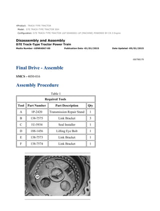
1. Product: TRACK-TYPE TRACTOR
Model: D7E TRACK-TYPE TRACTOR SSH
Configuration: D7E TRACK-TYPE TRACTOR LGP SSH00001-UP (MACHINE) POWERED BY C9.3 Engine
Disassembly and Assembly
D7E Track-Type Tractor Power Train
Media Number -UENR4067-00 Publication Date -01/01/2015 Date Updated -05/01/2015
i06798179
Final Drive - Assemble
SMCS - 4050-016
Assembly Procedure
Table 1
Required Tools
Tool Part Number Part Description Qty
A 1P-2420 Transmission Repair Stand 1
B 138-7575 Link Bracket 3
C 1U-5934 Seal Installer 1
D 188-1456 Lifting Eye Bolt 1
E 138-7573 Link Bracket 1
F 138-7574 Link Bracket 1
1/12
D7E TRACK-TYPE TRACTOR LGP SSH00001-UP (MACHINE) POWERED BY C...
2021/8/22
https://127.0.0.1/sisweb/sisweb/techdoc/techdoc_print_page.jsp?returnurl=/sis...
3. 4. Raise the temperature of the bearing (34) to a maximum temperature of 135 °C (275 °F).
Install bearing (34). Repeat for the other side. Apply oil to bearings.
Illustration 5 g01626522
5. Attach a suitable lifting device to gear (33) and install gear (33) in case assembly. The
weight of gear (33) is approximately 68 kg (150 lb).
Illustration 6 g02491111
6. Install cover (32). Install bolts (31).
Illustration 7 g01626504
3/12
D7E TRACK-TYPE TRACTOR LGP SSH00001-UP (MACHINE) POWERED BY C...
2021/8/22
https://127.0.0.1/sisweb/sisweb/techdoc/techdoc_print_page.jsp?returnurl=/sis...
4. 7. Reposition case assembly. Lower temperature of bearing (30). Install bearing (30).
Illustration 8 g01626497
8. Install pinion gear (29).
Illustration 9 g01626491
9. Install O-ring seal (28). Lower temperature of bearing (27). Install bearing (27).
Illustration 10 g01626488
10. Install cover (26) and bolts (25). Tighten bolts to a torque of 55 ± 10 N·m (40 ± 7 lb ft).
4/12
D7E TRACK-TYPE TRACTOR LGP SSH00001-UP (MACHINE) POWERED BY C...
2021/8/22
https://127.0.0.1/sisweb/sisweb/techdoc/techdoc_print_page.jsp?returnurl=/sis...
5. Illustration 11 g01626487
11. Install O-ring seal (24).
Illustration 12 g01627842
12. Install Tooling (B) onto housing (23). Attach a suitable lifting device to housing (23). The
weight of housing (23) is approximately 104 kg (230 lb). Install bolts (22). Tighten the bolts
to a torque of 460 ± 60 N·m (339 ± 44 lb ft).
5/12
D7E TRACK-TYPE TRACTOR LGP SSH00001-UP (MACHINE) POWERED BY C...
2021/8/22
https://127.0.0.1/sisweb/sisweb/techdoc/techdoc_print_page.jsp?returnurl=/sis...
6. Illustration 13 g01626455
Illustration 14 g01647154
13. Raise the temperature of the bearing cone (21) to a maximum temperature of 135 °C
(275 °F). Install bearing cone (21). Use Tooling (C) to install Duo-Cone seal (20).
Illustration 15 g01626453
14. Install bearing cup (19).
Illustration 16 g01625306
6/12
D7E TRACK-TYPE TRACTOR LGP SSH00001-UP (MACHINE) POWERED BY C...
2021/8/22
https://127.0.0.1/sisweb/sisweb/techdoc/techdoc_print_page.jsp?returnurl=/sis...
7. 15. Install bearing cup (18).
Illustration 17 g01625280
16. Install bearing cone (17).
Illustration 18 g02491176
17. Attach Tooling (B) to sprocket hub assembly (15). Attach a suitable lifting device to
sprocket hub assembly (15). The weight of sprocket hub assembly (15) is approximately
295 kg (650 lb). Install sprocket hub assembly (15).
7/12
D7E TRACK-TYPE TRACTOR LGP SSH00001-UP (MACHINE) POWERED BY C...
2021/8/22
https://127.0.0.1/sisweb/sisweb/techdoc/techdoc_print_page.jsp?returnurl=/sis...
8. Illustration 19 g02482520
18. Install hub assembly (14). Install retainer (13) and bolts (12). To properly seat the bearing
cone (17), install the bolts (12) in a crisscross pattern. Tighten bolts (12) to a torque of
120 ± 20 N·m (89 ± 15 lb ft).
Illustration 20 g02491277
19. Lower the temperature of bearing cups (11). Install bearing cups (11) in gears (9).
Illustration 21 g02491296
20. Install bearing cones (10) in each side of gears (9).
8/12
D7E TRACK-TYPE TRACTOR LGP SSH00001-UP (MACHINE) POWERED BY C...
2021/8/22
https://127.0.0.1/sisweb/sisweb/techdoc/techdoc_print_page.jsp?returnurl=/sis...
9. Illustration 22 g02491297
21. Put gears (9) in position in planetary carrier (5). Lower the temperature of shafts (8). Install
the shafts (8) in planetary carrier (5) and the gears (9). If necessary, use a press to install the
shafts (8). Install shafts (8) until the small end of the shaft extends 0.08 ± 0.05 mm (0.003 ±
0.002 inch) past the surface of the planetary carrier. Ensure that there is a metal to metal
contact between shafts (8) and the plates.
Illustration 23 g02482500
22. Install plates (7) and bolts (6).
Illustration 24 g02487582
9/12
D7E TRACK-TYPE TRACTOR LGP SSH00001-UP (MACHINE) POWERED BY C...
2021/8/22
https://127.0.0.1/sisweb/sisweb/techdoc/techdoc_print_page.jsp?returnurl=/sis...
10. 23. Attach Tooling (E) to planetary carrier (5). Attach a suitable lifting device to planetary
carrier (5). The weight of planetary carrier (5) is approximately 163 kg (360 lb). Install O-
ring seal (5A).
Illustration 25 g03840733
24. If equipped, install shields (4a) using bolts 1 through 10 shown in Illustration 25.
Illustration 26 g01624447
25. Install bolts (4). Tighten bolts (4) to a torque of 570 ± 80 N·m (420 ± 59 lb ft).
10/12
D7E TRACK-TYPE TRACTOR LGP SSH00001-UP (MACHINE) POWERED BY...
2021/8/22
https://127.0.0.1/sisweb/sisweb/techdoc/techdoc_print_page.jsp?returnurl=/sis...
11. Illustration 27 g01629995
26. Attach Tooling (D) to sun gear (3). Install sun gear (3).
Illustration 28 g01623825
27. Install cover (2) and bolts. Tighten bolts to a torque of 55 ± 10 N·m (41 ± 7 lb ft).
11/12
D7E TRACK-TYPE TRACTOR LGP SSH00001-UP (MACHINE) POWERED BY...
2021/8/22
https://127.0.0.1/sisweb/sisweb/techdoc/techdoc_print_page.jsp?returnurl=/sis...
12. Illustration 29 g02482720
28. Attach Tooling (F) to final drive assembly (1). Attach a suitable lifting device to final drive
assembly (1). The weight of final drive assembly (1) is approximately 880 kg (1940 lb).
Remove final drive assembly (1) from Tooling (A).
29. Install the final drives.
12/12
D7E TRACK-TYPE TRACTOR LGP SSH00001-UP (MACHINE) POWERED BY...
2021/8/22
https://127.0.0.1/sisweb/sisweb/techdoc/techdoc_print_page.jsp?returnurl=/sis...
13. Product: TRACK-TYPE TRACTOR
Model: D7E TRACK-TYPE TRACTOR SSH
Configuration: D7E TRACK-TYPE TRACTOR LGP SSH00001-UP (MACHINE) POWERED BY C9.3 Engine
Disassembly and Assembly
D7E Track-Type Tractor Power Train
Media Number -UENR4067-00 Publication Date -01/01/2015 Date Updated -05/01/2015
i03530625
Electronic Control Module (Generator) - Remove and Install
SMCS - 7610-010-DTN
Removal Procedure
Start By:
A. Perform the Electrical Shutdown and Voltage Discharge procedure.
B. Fully tilt the cab.
Illustration 1 g01859140
1. Disconnect harness assemblies (1) and (4). Remove bolts (3) and generator electronic
control module (2) .
Installation Procedure
1. Install generator electronic control module (2) in the reverse order of removal.
1/2
D7E TRACK-TYPE TRACTOR LGP SSH00001-UP (MACHINE) POWERED BY C...
2021/8/22
https://127.0.0.1/sisweb/sisweb/techdoc/techdoc_print_page.jsp?returnurl=/sis...
14. Product: TRACK-TYPE TRACTOR
Model: D7E TRACK-TYPE TRACTOR SSH
Configuration: D7E TRACK-TYPE TRACTOR LGP SSH00001-UP (MACHINE) POWERED BY C9.3 Engine
Disassembly and Assembly
D7E Track-Type Tractor Power Train
Media Number -UENR4067-00 Publication Date -01/01/2015 Date Updated -05/01/2015
i03530627
Electronic Control Module (Propulsion Module) - Remove
and Install
SMCS - 7610-010-DTN
Removal Procedure
Start By:
A. Perform the Electrical Shutdown and Voltage Discharge procedure.
B. Fully tilt the cab.
Illustration 1 g01859301
1. Disconnect harness assemblies (1) and (4). Remove bolts (3) and electronic control module
(2) .
Installation Procedure
1. Install electronic control module (2) in the reverse order of removal.
1/2
D7E TRACK-TYPE TRACTOR LGP SSH00001-UP (MACHINE) POWERED BY C...
2021/8/22
https://127.0.0.1/sisweb/sisweb/techdoc/techdoc_print_page.jsp?returnurl=/sis...
15. Product: TRACK-TYPE TRACTOR
Model: D7E TRACK-TYPE TRACTOR SSH
Configuration: D7E TRACK-TYPE TRACTOR LGP SSH00001-UP (MACHINE) POWERED BY C9.3 Engine
Disassembly and Assembly
D7E Track-Type Tractor Power Train
Media Number -UENR4067-00 Publication Date -01/01/2015 Date Updated -05/01/2015
i05985472
Gear Pump (Power Train) - Remove and Install
SMCS - 5073-010
Removal Procedure
Start By:
A. Fully Tilt the cab.
NOTICE
Care must be taken to ensure that fluids are contained during
performance of inspection, maintenance, testing, adjusting, and repair
of the product. Be prepared to collect the fluid with suitable containers
before opening any compartment or disassembling any component
containing fluids.
Refer to Special Publication, NENG2500, "Dealer Service Tool
Catalog" for tools and supplies suitable to collect and contain fluids on
Cat products.
Dispose of all fluids according to local regulations and mandates.
1. Drain the power train fluid. Refer to Operation and Maintenance Manual, "Power Train Oil
Level - Check".
1/2
D7E TRACK-TYPE TRACTOR LGP SSH00001-UP (MACHINE) POWERED BY C...
2021/8/22
https://127.0.0.1/sisweb/sisweb/techdoc/techdoc_print_page.jsp?returnurl=/sis...
16. Illustration 1 g01857453
2. Disconnect hose assemblies and harness assemblies in order to remove gear pump (1).
Attach a suitable lifting device to gear pump (1). The weight of gear pump (1) is
approximately 23 kg (50 lb). Remove gear pump (1) .
Installation Procedure
1. Install gear pump (1) in the reverse order of removal.
2/2
D7E TRACK-TYPE TRACTOR LGP SSH00001-UP (MACHINE) POWERED BY C...
2021/8/22
https://127.0.0.1/sisweb/sisweb/techdoc/techdoc_print_page.jsp?returnurl=/sis...
17. Product: TRACK-TYPE TRACTOR
Model: D7E TRACK-TYPE TRACTOR SSH
Configuration: D7E TRACK-TYPE TRACTOR LGP SSH00001-UP (MACHINE) POWERED BY C9.3 Engine
Disassembly and Assembly
D7E Track-Type Tractor Power Train
Media Number -UENR4067-00 Publication Date -01/01/2015 Date Updated -05/01/2015
i02987443
Gear Pump (Power Train) - Disassemble
SMCS - 5073-015
Disassembly Procedure
Start By:
A. Remove the gear pump.
Illustration 1 g01513894
1/5
D7E TRACK-TYPE TRACTOR LGP SSH00001-UP (MACHINE) POWERED BY C...
2021/8/22
https://127.0.0.1/sisweb/sisweb/techdoc/techdoc_print_page.jsp?returnurl=/sis...
18. Illustration 2 g01513965
1. Remove bolts (1) and bolts (2). Remove plate (3). Separate housing assembly (4) .
2. Remove coated washer (5) and steel washer (6) from bolts (2) .
Illustration 3 g01513973
3. Remove O-ring seal (7) from plate (3) .
2/5
D7E TRACK-TYPE TRACTOR LGP SSH00001-UP (MACHINE) POWERED BY C...
2021/8/22
https://127.0.0.1/sisweb/sisweb/techdoc/techdoc_print_page.jsp?returnurl=/sis...
19. Illustration 4 g01514450
4. Remove O-ring seal (8) from housing assembly (4) .
Illustration 5 g01514456
3/5
D7E TRACK-TYPE TRACTOR LGP SSH00001-UP (MACHINE) POWERED BY C...
2021/8/22
https://127.0.0.1/sisweb/sisweb/techdoc/techdoc_print_page.jsp?returnurl=/sis...
20. Illustration 6 g01514464
5. Remove gear (9), shaft (10), and gear (11) from housing assembly (4) .
6. Remove key (13) and remove shaft (12) .
Illustration 7 g01514472
7. Remove sleeve bearings (14) from housing assembly (4) .
Illustration 8 g01514480
8. Remove seals (15) and retaining ring (16) from housing assembly (4) .
4/5
D7E TRACK-TYPE TRACTOR LGP SSH00001-UP (MACHINE) POWERED BY C...
2021/8/22
https://127.0.0.1/sisweb/sisweb/techdoc/techdoc_print_page.jsp?returnurl=/sis...
22. Product: TRACK-TYPE TRACTOR
Model: D7E TRACK-TYPE TRACTOR SSH
Configuration: D7E TRACK-TYPE TRACTOR LGP SSH00001-UP (MACHINE) POWERED BY C9.3 Engine
Disassembly and Assembly
D7E Track-Type Tractor Power Train
Media Number -UENR4067-00 Publication Date -01/01/2015 Date Updated -05/01/2015
i02987444
Gear Pump (Power Train) - Assemble
SMCS - 5073-016
Assembly Procedure
Table 1
Required Tools
Tool Part Number Part Description Qty
A 1P-0510 Driver Gp 1
Illustration 1 g01514502
1/6
D7E TRACK-TYPE TRACTOR LGP SSH00001-UP (MACHINE) POWERED BY C...
2021/8/22
https://127.0.0.1/sisweb/sisweb/techdoc/techdoc_print_page.jsp?returnurl=/sis...
23. Illustration 2 g01515994
(X) 1.50 ± 0.25 mm (0.059 ± 0.010 inch)
(Y) 30° ± 15°
Note: Be sure to install sleeve bearings (17) to a depth of Dimension (X). The joints on
sleeve bearings (17) must be installed to the angle of Dimension (Y) .
1. Lower the temperature of sleeve bearings (17). Use Tooling (A) in order to install sleeve
bearings (17) into housing assembly (4) .
2/6
D7E TRACK-TYPE TRACTOR LGP SSH00001-UP (MACHINE) POWERED BY C...
2021/8/22
https://127.0.0.1/sisweb/sisweb/techdoc/techdoc_print_page.jsp?returnurl=/sis...
24. Illustration 3 g01514480
2. Use Tooling (A) in order to install seals (15). Install seals (15) and retaining ring (16) into
housing assembly (4). Lubricate the sealing lip of seals (15) with lubricant that is being
sealed.
Illustration 4 g01514472
Illustration 5 g01516025
(X) 1.50 ± 0.25 mm (0.059 ± 0.010 inch)
3/6
D7E TRACK-TYPE TRACTOR LGP SSH00001-UP (MACHINE) POWERED BY C...
2021/8/22
https://127.0.0.1/sisweb/sisweb/techdoc/techdoc_print_page.jsp?returnurl=/sis...
25. (Y) 30° ± 15°
Note: Be sure to install sleeve bearings (14) to a depth of Dimension (X). The joints on
sleeve bearings (14) must be installed to the angle of Dimension (Y) .
3. Lower the temperature of sleeve bearings (14). Use Tooling (A) in order to install sleeve
bearings (14) into housing assembly (4) .
Illustration 6 g01514464
Illustration 7 g01514456
4. Install shaft (12) and install key (13) .
5. Install gear (11), shaft (10), and gear (9) into housing assembly (4) .
4/6
D7E TRACK-TYPE TRACTOR LGP SSH00001-UP (MACHINE) POWERED BY C...
2021/8/22
https://127.0.0.1/sisweb/sisweb/techdoc/techdoc_print_page.jsp?returnurl=/sis...
26. Suggest:
If the above button click is invalid.
Please download this document
first, and then click the above link
to download the complete manual.
Thank you so much for reading
27. Illustration 8 g01514450
6. Install O-ring seal (8) into housing assembly (4) .
Illustration 9 g01513973
7. Install O-ring seal (7) into plate (3) .
5/6
D7E TRACK-TYPE TRACTOR LGP SSH00001-UP (MACHINE) POWERED BY C...
2021/8/22
https://127.0.0.1/sisweb/sisweb/techdoc/techdoc_print_page.jsp?returnurl=/sis...
28. Illustration 10 g01513965
Illustration 11 g01513894
8. Install coated washer (5) and steel washer (6) onto bolts (2) .
9. Connect housing assembly (4). Position plate (3). Install bolts (2) and bolts (1) .
End By: Install the gear pump.
6/6
D7E TRACK-TYPE TRACTOR LGP SSH00001-UP (MACHINE) POWERED BY C...
2021/8/22
https://127.0.0.1/sisweb/sisweb/techdoc/techdoc_print_page.jsp?returnurl=/sis...