This document provides instructions for disassembling and assembling the final drive of a D7E track-type tractor. It outlines 31 steps to disassemble the final drive components including gears, bearings, seals and housings. It then describes 19 steps for reassembling the final drive, including heating components to specific temperatures before pressing them in place and torquing bolts to specified values. The purpose is to provide maintenance technicians with a procedure to fully disassemble and reassemble the tractor's final drive transmission.
Caterpillar Cat D7R II TRACK-TYPE TRACTOR (Prefix ACS) Service Repair Manual ...f8uuseidjkmm
This document provides instructions for disassembling and assembling the final drive of a D7R II track-type tractor. It lists the required tools and presents 30 steps for disassembly, including removing gears, shafts, bearings and seals. It then lists 21 steps for assembly, installing components in reverse order and noting specifics like torque values and clearances between parts. The overall procedure involves dismantling both sides of the final drive unit and carefully removing and replacing numerous components.
Caterpillar Cat D7R II TRACK-TYPE TRACTOR (Prefix ACS) Service Repair Manual ...f7useijdkdmd
This document provides instructions for disassembling and assembling the final drive of a D7R II track-type tractor. It describes 30 steps to disassemble the final drive which includes removing gears, shafts, bearings and seals. It then describes 27 steps for assembly, including lowering temperatures of parts before installation and using various tools to install seals, gears and shafts. Tolerances are provided for clearances between parts.
Caterpillar Cat D7R II TRACK-TYPE TRACTOR (Prefix ACS) Service Repair Manual ...8fisiodkdmm3e
This document provides instructions for disassembling and assembling the final drive of a D7R II track-type tractor. It describes in 30 steps how to disassemble components such as gears, shafts, bearings and seals. It then describes in 27 steps the reverse process of assembling these components, including specifics on tooling used, component weights, bolt torques and clearance measurements. The overall document provides detailed technical specifications for maintenance and repair of the final drive system.
Caterpillar Cat D7R II TRACK-TYPE TRACTOR (Prefix ACS) Service Repair Manual ...jichenwaixz37
This document provides instructions for disassembling and assembling the final drive of a D7R II track-type tractor. It lists 30 steps for disassembly, removing components like gears, shafts, seals and bearings. It then lists 27 steps for assembly, providing details on cleaning, heating/cooling parts, and using specialty tools to reinstall components in the reverse order of disassembly. Tolerances are specified for clearances between parts.
Caterpillar Cat D7R II TRACK-TYPE TRACTOR (Prefix ACS) Service Repair Manual ...aoxs635594
This document provides instructions for disassembling and assembling the final drive of a D7R II track-type tractor. It describes 30 steps to disassemble the final drive which includes removing gears, shafts, bearings and seals. It then describes 27 steps for assembly, including lowering temperatures of parts before installation and using various tools to install seals, shafts, gears and other components. Tolerances are provided for clearances between parts.
Caterpillar Cat D7R II TRACK-TYPE TRACTOR (Prefix ACS) Service Repair Manual ...jnnfnjsdnnd
This document provides instructions for disassembling and assembling the final drive of a D7R II track-type tractor. It describes in 30 steps how to disassemble components such as gears, shafts, bearings and seals. It then describes the 23 steps to assemble these components in reverse order, including precautions for installing seals and retaining rings and verifying clearances with tools. The overall process involves lifting heavy components weighing up to 260 kg with the aid of lifting devices and specialized tools.
Caterpillar Cat D7R II TRACK-TYPE TRACTOR (Prefix ACS) Service Repair Manual ...ufjsekddmmd
This document provides instructions for disassembling and assembling the final drive of a D7R II track-type tractor. It describes in 30 steps how to remove and install various components of the final drive such as gears, shafts, bearings and seals. Special tools are required to remove items like planetary carriers and hubs due to the heavy weights involved. Precise alignment and temperature control of parts is important during assembly to avoid damage.
Caterpillar Cat D7R II TRACK-TYPE TRACTOR (Prefix ACS) Service Repair Manual ...f8ueijdkdm8u
This document provides instructions for disassembling and assembling the final drive of a D7R II track-type tractor. It describes in 30 steps how to remove components such as gears, shafts, bearings and seals. Tools required are listed. The assembly process is then described in 18 steps, including installing seals, bearings and gears using various tools to position components. Precise measurements are specified to ensure correct clearance between parts.
Caterpillar Cat D7R II TRACK-TYPE TRACTOR (Prefix ACS) Service Repair Manual ...ujkfdkkmsmd
This document provides instructions for disassembling and assembling the final drive of a D7R II track-type tractor. It lists the required tools and presents a 30 step procedure for disassembly that includes removing gears, shafts, bearings and seals. The 17 step assembly procedure provides instructions for installing these components in reverse order and notes temperature and torque specifications.
Caterpillar Cat D7R II TRACK-TYPE TRACTOR (Prefix ACS) Service Repair Manual ...ujdjksmdmdm
This document provides instructions for disassembling and assembling the final drive of a D7R II track-type tractor. It describes 30 steps to disassemble the final drive which includes removing gears, shafts, bearings and seals. It then describes 27 steps for assembly, including lowering temperatures of parts before installation and using various tools to install seals, gears, shafts and carriers. Precise measurements are required during assembly to ensure proper clearance between parts.
The document provides instructions for disassembling and assembling the final drive and sprocket of a 973K track loader. It details removing components like the final drive, sprocket segments, housing assembly, shaft and gear assembly, ring gear, hub, seals and bearings. It also describes assembling the components in reverse order and notes tools required like pullers, presses and brackets. Precautions are included like maximum pressures and checking components for wear before assembly.
Caterpillar Cat 973 and 973K Track Loader (Prefix MKL) Service Repair Manual ...9fiisekodkdmd
The document provides instructions for disassembling and assembling the final drive and sprocket of a 973K track loader. It lists the required tools and parts. The disassembly process involves removing the final drive, sprocket segments, covers, gears, shafts, seals, and bearings. The assembly process reverses the disassembly steps and provides details on heating and positioning components, applying sealant, and tightening fasteners to the specified torques.
The document provides instructions for disassembling and assembling the final drive and sprocket of a 973K track loader. It lists the required tools and parts. The disassembly process involves removing 17 components including the final drive, sprocket segments, housing assembly, gears, seals and bearings. The assembly process lists 29 steps to reinstall the components in reverse order, noting requirements like applying threadlocker and heating/cooling parts.
The document provides instructions for disassembling and assembling the final drive and sprocket of a 973K track loader. It details removing components like the final drive, sprocket segments, housing assembly, gears, seals, and bearings. Tools required are listed. Assembly involves lowering or raising temperatures of parts and installing components in reverse order of disassembly while applying lubricants and following torque specifications.
Caterpillar Cat 973 and 973K Track Loader (Prefix MKL) Service Repair Manual ...9fikslkddmd8u
The document provides instructions for disassembling and assembling the final drive and sprocket of a 973K track loader. It lists the required tools and parts. The disassembly process involves removing the final drive, sprocket segments, covers, gears, shafts, seals, and bearings. The assembly process reverses the disassembly steps and provides details on heating and positioning components, applying threadlocker, and tightening fasteners to the specified torques.
The document provides instructions for disassembling and assembling the final drive and sprocket of a 973K track loader. It details removing over 20 components including the final drive, sprocket segments, various gears, seals, bearings and hubs. Special tools are required and components need to be heated or cooled to aid in removal and installation. Precise torques and end play measurements must be followed during reassembly.
The document provides instructions for disassembling and assembling the final drive and sprocket of a 973K track loader. It lists the required tools and parts. The disassembly process involves removing the final drive, sprocket segments, covers, gears, shafts, seals, bearings and other components. The assembly process reverses the disassembly steps and provides details on cleaning, inspecting, heating and applying compound to parts before reinstallation. Precise torques are specified for bolts.
The document provides instructions for disassembling and assembling the final drive and sprocket of a 973K track loader. It lists the required tools and parts. The disassembly process involves removing the final drive, sprocket segments, covers, gears, shafts, seals, and bearings. The assembly process reverses the disassembly steps and provides details on heating and positioning components, applying sealant, and tightening fasteners to the specified torques.
The document provides instructions for disassembling and assembling the final drive and sprocket of a 973K track loader. It details removing over 20 components including the final drive, sprocket segments, various gears, seals, bearings and hubs. Special tools are required and components need to be heated or cooled to aid in removal and installation. Precise torques and end play measurements must be followed during reassembly.
The document provides instructions for disassembling and assembling the final drive and sprocket of a 973K track loader. It lists the required tools and parts. The disassembly process involves removing 17 components including the final drive, sprocket segments, housing assembly, gears, seals and bearings. The assembly process lists 29 steps to reinstall the components in reverse order, noting requirements like applying threadlocker and heating/cooling parts.
The document provides instructions for disassembling and assembling the final drive and sprocket of a 973K track loader. It lists the required tools and parts. The disassembly process involves removing the final drive, sprocket segments, covers, gears, shafts, seals, bearings and other components. The assembly process reverses the disassembly steps and provides details on cleaning, inspecting, heating and applying compound to parts before reinstallation.
The document provides instructions for disassembling and assembling the final drive and sprocket of a 973K track loader. It lists the required tools and parts. The disassembly process involves removing 17 components including the final drive, sprocket segments, housing assembly, gears, seals and bearings. The assembly process reverses this, heating and cooling components as needed and applying threadlock to fasteners. Precise torques are specified for reinstallation.
The document provides instructions for disassembling and assembling the final drive and sprocket of a 973K track loader. It lists the required tools and parts. The disassembly process involves removing the final drive, sprocket segments, covers, gears, shafts, seals, and bearings. The assembly process reverses the disassembly steps and provides details on heating and positioning components, applying sealant, and tightening fasteners to the specified torques.
The document provides instructions for disassembling and assembling the final drive and sprocket of a 973K track loader. It details removing over 20 components including the final drive, sprocket segments, housing assembly, shaft and gear assembly, ring gear, hub, seals and bearings. Tools required are listed and each step includes illustrations showing the component locations. Heating and cooling some components is necessary before installation to ensure a proper fit.
The document provides instructions for disassembling and assembling the final drive and sprocket of a 973K track loader. It details removing over 20 components including the final drive, sprocket segments, various gears, seals, bearings and hubs. Special tools are required and components need to be heated or cooled to aid in removal and installation. Precise tolerances and torque specifications must be followed to properly reassemble the drive train.
The document provides instructions for disassembling and assembling the final drive and sprocket of a 973K track loader. It lists the required tools and parts. The disassembly process involves removing 17 components including the final drive, sprocket segments, housing assembly, gears, seals and bearings. The assembly process lists 29 steps to reinstall the components in reverse order, noting requirements like applying threadlocker and heating/cooling parts.
Massey Ferguson MF 384 S TRACTOR (- 300993) Parts Catalogue Manual Instant Do...onyvzcwadtu05
This document contains parts listings and technical specifications for the engine of a Massey Ferguson 384 S tractor. It includes 6 pages detailing over 60 individual parts for the engine, including the cylinder block, crankshaft, pistons, cylinder head, rocker shaft, and air induction and exhaust systems. Each part is listed with its part number, quantity, description, and any relevant comments.
Massey Ferguson MF 384 F TRACTOR, - 0894 Parts Catalogue Manual Instant Downl...onyvzcwadtu05
The document is a parts catalog for a Massey Ferguson MF 384 F tractor engine. It lists over 60 individual parts for the engine, including the cylinder block, crankshaft, pistons, connecting rods, cylinder head, rocker shaft and other components. Each part is given a reference number, part number, quantity and description, along with any replacement or additional part information.
The document suggests that if clicking the above button is invalid, the user should first download the document and then click the link to download the complete manual. It thanks the reader for their time.
This document provides instructions for disassembling and assembling the main hydraulic pump on a M315D Wheeled Excavator. It lists 34 steps for disassembly, removing components like pistons, springs, seals and housing pieces. It then lists 36 steps for assembly, installing components in reverse order and noting proper orientation of marked parts. Precautions are provided regarding contained fluids, released spring forces, and keeping parts clean from contaminants. Required specialty tools are also listed.
More Related Content
Similar to Caterpillar Cat D7E TRACK-TYPE TRACTOR (Prefix TAN) Service Repair Manual Instant Download.pdf
Caterpillar Cat D7R II TRACK-TYPE TRACTOR (Prefix ACS) Service Repair Manual ...ujkfdkkmsmd
This document provides instructions for disassembling and assembling the final drive of a D7R II track-type tractor. It lists the required tools and presents a 30 step procedure for disassembly that includes removing gears, shafts, bearings and seals. The 17 step assembly procedure provides instructions for installing these components in reverse order and notes temperature and torque specifications.
Caterpillar Cat D7R II TRACK-TYPE TRACTOR (Prefix ACS) Service Repair Manual ...ujdjksmdmdm
This document provides instructions for disassembling and assembling the final drive of a D7R II track-type tractor. It describes 30 steps to disassemble the final drive which includes removing gears, shafts, bearings and seals. It then describes 27 steps for assembly, including lowering temperatures of parts before installation and using various tools to install seals, gears, shafts and carriers. Precise measurements are required during assembly to ensure proper clearance between parts.
The document provides instructions for disassembling and assembling the final drive and sprocket of a 973K track loader. It details removing components like the final drive, sprocket segments, housing assembly, shaft and gear assembly, ring gear, hub, seals and bearings. It also describes assembling the components in reverse order and notes tools required like pullers, presses and brackets. Precautions are included like maximum pressures and checking components for wear before assembly.
Caterpillar Cat 973 and 973K Track Loader (Prefix MKL) Service Repair Manual ...9fiisekodkdmd
The document provides instructions for disassembling and assembling the final drive and sprocket of a 973K track loader. It lists the required tools and parts. The disassembly process involves removing the final drive, sprocket segments, covers, gears, shafts, seals, and bearings. The assembly process reverses the disassembly steps and provides details on heating and positioning components, applying sealant, and tightening fasteners to the specified torques.
The document provides instructions for disassembling and assembling the final drive and sprocket of a 973K track loader. It lists the required tools and parts. The disassembly process involves removing 17 components including the final drive, sprocket segments, housing assembly, gears, seals and bearings. The assembly process lists 29 steps to reinstall the components in reverse order, noting requirements like applying threadlocker and heating/cooling parts.
The document provides instructions for disassembling and assembling the final drive and sprocket of a 973K track loader. It details removing components like the final drive, sprocket segments, housing assembly, gears, seals, and bearings. Tools required are listed. Assembly involves lowering or raising temperatures of parts and installing components in reverse order of disassembly while applying lubricants and following torque specifications.
Caterpillar Cat 973 and 973K Track Loader (Prefix MKL) Service Repair Manual ...9fikslkddmd8u
The document provides instructions for disassembling and assembling the final drive and sprocket of a 973K track loader. It lists the required tools and parts. The disassembly process involves removing the final drive, sprocket segments, covers, gears, shafts, seals, and bearings. The assembly process reverses the disassembly steps and provides details on heating and positioning components, applying threadlocker, and tightening fasteners to the specified torques.
The document provides instructions for disassembling and assembling the final drive and sprocket of a 973K track loader. It details removing over 20 components including the final drive, sprocket segments, various gears, seals, bearings and hubs. Special tools are required and components need to be heated or cooled to aid in removal and installation. Precise torques and end play measurements must be followed during reassembly.
The document provides instructions for disassembling and assembling the final drive and sprocket of a 973K track loader. It lists the required tools and parts. The disassembly process involves removing the final drive, sprocket segments, covers, gears, shafts, seals, bearings and other components. The assembly process reverses the disassembly steps and provides details on cleaning, inspecting, heating and applying compound to parts before reinstallation. Precise torques are specified for bolts.
The document provides instructions for disassembling and assembling the final drive and sprocket of a 973K track loader. It lists the required tools and parts. The disassembly process involves removing the final drive, sprocket segments, covers, gears, shafts, seals, and bearings. The assembly process reverses the disassembly steps and provides details on heating and positioning components, applying sealant, and tightening fasteners to the specified torques.
The document provides instructions for disassembling and assembling the final drive and sprocket of a 973K track loader. It details removing over 20 components including the final drive, sprocket segments, various gears, seals, bearings and hubs. Special tools are required and components need to be heated or cooled to aid in removal and installation. Precise torques and end play measurements must be followed during reassembly.
The document provides instructions for disassembling and assembling the final drive and sprocket of a 973K track loader. It lists the required tools and parts. The disassembly process involves removing 17 components including the final drive, sprocket segments, housing assembly, gears, seals and bearings. The assembly process lists 29 steps to reinstall the components in reverse order, noting requirements like applying threadlocker and heating/cooling parts.
The document provides instructions for disassembling and assembling the final drive and sprocket of a 973K track loader. It lists the required tools and parts. The disassembly process involves removing the final drive, sprocket segments, covers, gears, shafts, seals, bearings and other components. The assembly process reverses the disassembly steps and provides details on cleaning, inspecting, heating and applying compound to parts before reinstallation.
The document provides instructions for disassembling and assembling the final drive and sprocket of a 973K track loader. It lists the required tools and parts. The disassembly process involves removing 17 components including the final drive, sprocket segments, housing assembly, gears, seals and bearings. The assembly process reverses this, heating and cooling components as needed and applying threadlock to fasteners. Precise torques are specified for reinstallation.
The document provides instructions for disassembling and assembling the final drive and sprocket of a 973K track loader. It lists the required tools and parts. The disassembly process involves removing the final drive, sprocket segments, covers, gears, shafts, seals, and bearings. The assembly process reverses the disassembly steps and provides details on heating and positioning components, applying sealant, and tightening fasteners to the specified torques.
The document provides instructions for disassembling and assembling the final drive and sprocket of a 973K track loader. It details removing over 20 components including the final drive, sprocket segments, housing assembly, shaft and gear assembly, ring gear, hub, seals and bearings. Tools required are listed and each step includes illustrations showing the component locations. Heating and cooling some components is necessary before installation to ensure a proper fit.
The document provides instructions for disassembling and assembling the final drive and sprocket of a 973K track loader. It details removing over 20 components including the final drive, sprocket segments, various gears, seals, bearings and hubs. Special tools are required and components need to be heated or cooled to aid in removal and installation. Precise tolerances and torque specifications must be followed to properly reassemble the drive train.
The document provides instructions for disassembling and assembling the final drive and sprocket of a 973K track loader. It lists the required tools and parts. The disassembly process involves removing 17 components including the final drive, sprocket segments, housing assembly, gears, seals and bearings. The assembly process lists 29 steps to reinstall the components in reverse order, noting requirements like applying threadlocker and heating/cooling parts.
Similar to Caterpillar Cat D7E TRACK-TYPE TRACTOR (Prefix TAN) Service Repair Manual Instant Download.pdf (18)
Massey Ferguson MF 384 S TRACTOR (- 300993) Parts Catalogue Manual Instant Do...onyvzcwadtu05
This document contains parts listings and technical specifications for the engine of a Massey Ferguson 384 S tractor. It includes 6 pages detailing over 60 individual parts for the engine, including the cylinder block, crankshaft, pistons, cylinder head, rocker shaft, and air induction and exhaust systems. Each part is listed with its part number, quantity, description, and any relevant comments.
Massey Ferguson MF 384 F TRACTOR, - 0894 Parts Catalogue Manual Instant Downl...onyvzcwadtu05
The document is a parts catalog for a Massey Ferguson MF 384 F tractor engine. It lists over 60 individual parts for the engine, including the cylinder block, crankshaft, pistons, connecting rods, cylinder head, rocker shaft and other components. Each part is given a reference number, part number, quantity and description, along with any replacement or additional part information.
The document suggests that if clicking the above button is invalid, the user should first download the document and then click the link to download the complete manual. It thanks the reader for their time.
This document provides instructions for disassembling and assembling the main hydraulic pump on a M315D Wheeled Excavator. It lists 34 steps for disassembly, removing components like pistons, springs, seals and housing pieces. It then lists 36 steps for assembly, installing components in reverse order and noting proper orientation of marked parts. Precautions are provided regarding contained fluids, released spring forces, and keeping parts clean from contaminants. Required specialty tools are also listed.
This document provides instructions for assembling the main hydraulic pump on an excavator model. It lists the required tools and parts. It then provides 49 steps with accompanying illustrations, describing how to install each component of the pump in detail, including bearings, seals, pistons, springs, and valves. The final step instructs the technician to install the assembled pump.
The document provides instructions for installing a swing drive on an excavator model M315D. It lists the required tools and parts. The procedure involves 28 steps, including installing bearings, seals, gears, and other components into the swing drive housing. Specific torque specifications and dimensional checks are listed to ensure proper assembly. Installation is completed by positioning the swing drive in the swing brake housing and securing it with bolts.
This document provides instructions for removing and installing a pilot control valve on a D10 track-type tractor. Key steps include removing the right side console cover, disconnecting control rods from the valve spools using pins and cotter pins, labeling and disconnecting all oil lines, and removing bolts to take off the pilot control valve. Reinstallation involves installing the pilot control valve on the bracket with bolts, connecting the labeled oil lines, and attaching the control rods to the valve spools with pins and cotter pins.
This document provides instructions for disassembling and assembling the final drive of a D9R track-type tractor. It describes removing components such as the planetary carrier, gears, shafts, and hub. Various tools are required, including link brackets, a push-puller tool group, driver group, and hydraulic cylinder assembly. Precautions are given for using hydraulic cylinders and puller studs during disassembly. The multi-step process includes pressing, lifting, and removing components from the planetary carrier, sun gear, and hub.
This document provides instructions to disassemble and assemble the final drive of a D9R track-type tractor. It describes:
1) Removing over 30 components of the final drive including gears, shafts, bearings, seals and hubs using various tools.
2) Inspecting all parts and replacing any that are damaged.
3) Heating some bearings cones to aid removal and ensuring proper temperatures when installing.
4) Precisely assembling the components in reverse order, taking care with sealing surfaces.
1) The document provides instructions for removing and installing the final drive planetary carrier in a D9R track-type tractor.
2) It describes using various tools to remove the carrier, hub components, seals, and gears. It then explains how to clean and prepare the parts for installation and use the tools to reinstall the components in reverse order.
3) Fourteen steps are outlined to remove the carrier and twelve steps are provided to install it back into the final drive assembly.
The document provides instructions for disassembling and assembling the steering clutch and brake of a Caterpillar D7R track-type tractor. It details 20 steps to disassemble the components which include removing bolts, plates, bearings, seals and other parts. The 20 steps to assemble are also outlined and include cleaning parts, applying oil, heating bearings, and reinstalling components in reverse order. Special safety precautions are noted regarding spring loaded components.
The document provides assembly instructions for installing a final drive on a D7R track-type tractor. It describes 31 steps to assemble bearings, seals, gears, shafts, covers and other components. Tools required include drivers, seal installers, brackets and spacers. Precise torques and clearances are specified. The assembly is completed by filling the final drive with oil and reconnecting the track.
Caterpillar Cat D7R II WATER FORDING TRACTOR (Prefix DJT) Service Repair Manu...onyvzcwadtu05
This document provides instructions for disassembling and assembling the steering planetary and brake of a D7R Series II Water Fording Tractor. It describes removing 24 components including the planetary group, brake, ring gear, friction discs, piston, and springs. Reassembly involves installing these components in reverse order, noting proper orientation and torque specifications. Tools required include link brackets, a driver group, forcing bolts, and sealant.
Caterpillar Cat D7R II TRACK-TYPE TRACTOR (Prefix AGN) Service Repair Manual ...onyvzcwadtu05
The document provides instructions for removing a final drive, steering planetary, and brake assembly from a D7R II track-type tractor. It describes using lifting brackets, shackles, bolts and nuts to attach a hoist to the assembly and remove it from the tractor. The assembly weighs approximately 800 kg (1750 lb) and precautions are listed to provide means to stop the machine without the brake installed. Fluids must be contained while working on components to collect any fluids that may drain out.
This document provides instructions for disassembling and assembling the final drives on a D7H track-type tractor. The main steps for disassembly are to remove the final drives from the machine, then disassemble the internal components which include removing planet carriers, gears, shafts, and bearings. For assembly, the components are installed in reverse order, with specifics on cleaning, heating/cooling parts, and using installation tools to properly set clearances and ensure metal-to-metal contact between parts.
This document provides instructions for servicing the final drives on a D7H track-type tractor. It describes how to remove and disassemble the final drives, including removing the planet carriers, gears, shafts and other components. It then describes how to assemble the final drives, including installing bearings, seals, rings and other parts back into the hubs and carriers. The goal is to provide maintenance technicians with step-by-step directions for servicing these critical components.
1) The document provides instructions for removing and installing pistons, connecting rods, connecting rod bearings, and crankshaft main bearings for a Caterpillar 3306 engine.
2) The procedure involves using tools to compress piston rings, installing pistons and connecting rods onto the crankshaft, checking clearances of connecting rod bearings, and removing/installing main bearing caps.
3) Technicians are advised to keep all parts clean and lubricated with engine oil to prevent damage and wear.
The document provides instructions for removing and installing sprocket assemblies on a track-type tractor. It involves 22 steps to remove the assemblies, which includes draining oil, removing seals, bearings, and other components. The 23 steps to install include pressing in new seals, bearings, and sprockets using specialized tools and applying precise forces, and adjusting bearings after reinstalling track roller frames. Proper cleaning, lubrication and torque specifications are noted throughout.
The document provides step-by-step instructions for removing and installing sprocket assemblies on a final drive case. It involves draining oil, removing the sprocket and various components using specialized tools, cleaning surfaces, replacing seals, installing new components in reverse order, and filling with oil. Proper alignment and torque specifications are noted throughout.
The document provides instructions for removing and installing final drive case assemblies on a D7G track-type tractor. It describes draining oil from the final drive case and removing components like caps, locks, nuts, seals and bearings. It explains using tools and hoists to separate the sprocket, holder assembly and adjusting nut as a unit from the tapered sprocket shaft. Finally, it outlines reinstalling the sprocket assembly and adjusting the bearings.
Fleet management these days is next to impossible without connected vehicle solutions. Why? Well, fleet trackers and accompanying connected vehicle management solutions tend to offer quite a few hard-to-ignore benefits to fleet managers and businesses alike. Let’s check them out!
Ever been troubled by the blinking sign and didn’t know what to do?
Here’s a handy guide to dashboard symbols so that you’ll never be confused again!
Save them for later and save the trouble!
Welcome to ASP Cranes, your trusted partner for crane solutions in Raipur, Chhattisgarh! With years of experience and a commitment to excellence, we offer a comprehensive range of crane services tailored to meet your lifting and material handling needs.
At ASP Cranes, we understand the importance of reliable and efficient crane operations in various industries, from construction and manufacturing to logistics and infrastructure development. That's why we strive to deliver top-notch solutions that enhance productivity, safety, and cost-effectiveness for our clients.
Our services include:
Crane Rental: Whether you need a crawler crane for heavy lifting or a hydraulic crane for versatile operations, we have a diverse fleet of well-maintained cranes available for rent. Our rental options are flexible and can be customized to suit your project requirements.
Crane Sales: Looking to invest in a crane for your business? We offer a wide selection of new and used cranes from leading manufacturers, ensuring you find the perfect equipment to match your needs and budget.
Crane Maintenance and Repair: To ensure optimal performance and safety, regular maintenance and timely repairs are essential for cranes. Our team of skilled technicians provides comprehensive maintenance and repair services to keep your equipment running smoothly and minimize downtime.
Crane Operator Training: Proper training is crucial for safe and efficient crane operation. We offer specialized training programs conducted by certified instructors to equip operators with the skills and knowledge they need to handle cranes effectively.
Custom Solutions: We understand that every project is unique, which is why we offer custom crane solutions tailored to your specific requirements. Whether you need modifications, attachments, or specialized equipment, we can design and implement solutions that meet your needs.
At ASP Cranes, customer satisfaction is our top priority. We are dedicated to delivering reliable, cost-effective, and innovative crane solutions that exceed expectations. Contact us today to learn more about our services and how we can support your project in Raipur, Chhattisgarh, and beyond. Let ASP Cranes be your trusted partner for all your crane needs!
The Octavia range embodies the design trend of the Škoda brand: a fusion of
aesthetics, safety and practicality. Whether you see the car as a whole or step
closer and explore its unique features, the Octavia range radiates with the
harmony of functionality and emotion
What Could Be Behind Your Mercedes Sprinter's Power Loss on Uphill RoadsSprinter Gurus
Unlock the secrets behind your Mercedes Sprinter's uphill power loss with our comprehensive presentation. From fuel filter blockages to turbocharger troubles, we uncover the culprits and empower you to reclaim your vehicle's peak performance. Conquer every ascent with confidence and ensure a thrilling journey every time.
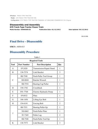
1. Product: TRACK-TYPE TRACTOR
Model: D7E TRACK-TYPE TRACTOR TAN
Configuration: D7E TRACK-TYPE TRACTOR TAN00001-UP (MACHINE) POWERED BY C9.3 Engine
Disassembly and Assembly
D7E Track-Type Tractor Power Train
Media Number -KENR5606-03 Publication Date -01/12/2012 Date Updated -05/12/2012
i06161086
Final Drive - Disassemble
SMCS - 4050-015
Disassembly Procedure
Table 1
Required Tools
Tool Part Number Part Description Qty
A 1P-2420 Transmission Repair Stand 1
B 138-7574 Link Bracket 3
C
8B-7548 Push-Puller Tool Group 1
8H-0684 Ratchet Wrench 1
8B-7554 Bearing Cup Puller 1
D 150-1782 Crossblock 1
E 350 -7768 Electric Hydraulic Pump 1
F 1P-0532 Plate 1
G 188-1456 Lifting Eye Bolt 1
H 154-6181 Forcing Bolt 2
J
8B-7551 Bearing Puller Gp 1
3H-0465 Push-Puller Plate 1
5F-7369 Puller Leg 2
8B-7548 Push-Puller Tool Gp 1
K 138-7573 Link Bracket 3
1/14
D7E TRACK-TYPE TRACTOR TAN00001-UP (MACHINE) POWERED BY C9.3 ...
2021/8/21
https://127.0.0.1/sisweb/sisweb/techdoc/techdoc_print_page.jsp?returnurl=/sis...
2. Start By:
A. Remove the final drive.
1. Drain the oil from the final drive into a suitable container for storage or disposal.
Illustration 1 g01623802
2. Attach Tooling (B) and a suitable lifting device to final drive (1) . The weight of final drive
assembly (1) is approximately 880 kg (1940 lb). Attach final drive assembly (1) to Tooling
(A) .
Illustration 2 g01623825
3. Remove cover (2) .
2/14
D7E TRACK-TYPE TRACTOR TAN00001-UP (MACHINE) POWERED BY C9.3 ...
2021/8/21
https://127.0.0.1/sisweb/sisweb/techdoc/techdoc_print_page.jsp?returnurl=/sis...
3. Illustration 3 g01624420
4. Attach Tooling (G) to sun gear (3) .
Illustration 4 g03840733
5. If equipped, remove shields (4a) by removing bolts 1 through 10 shown in Illustration 4.
3/14
D7E TRACK-TYPE TRACTOR TAN00001-UP (MACHINE) POWERED BY C9.3 ...
2021/8/21
https://127.0.0.1/sisweb/sisweb/techdoc/techdoc_print_page.jsp?returnurl=/sis...
4. Illustration 5 g01624447
6. Remove bolts (4) .
Illustration 6 g02487582
7. Attach a suitable lifting device and Tooling (K) in order to remove planetary carrier (5) .
The weight of planetary carrier (5) is approximately 163 kg (360 lb). Remove O-ring (5A) .
Illustration 7 g02482500
4/14
D7E TRACK-TYPE TRACTOR TAN00001-UP (MACHINE) POWERED BY C9.3 ...
2021/8/21
https://127.0.0.1/sisweb/sisweb/techdoc/techdoc_print_page.jsp?returnurl=/sis...
5. 8. Remove bolts (6) and plate (7) .
Illustration 8 g01624699
9. Use a suitable press to remove shafts (8) from the planetary carrier.
Illustration 9 g01624716
10. Remove gears (9) from the planetary carrier.
11. Remove bearing cones (10) from each side of gears (9) .
5/14
D7E TRACK-TYPE TRACTOR TAN00001-UP (MACHINE) POWERED BY C9.3 ...
2021/8/21
https://127.0.0.1/sisweb/sisweb/techdoc/techdoc_print_page.jsp?returnurl=/sis...
6. Illustration 10 g01624720
12. Remove bearing cups (11) from each side of gears (9) with Tooling (C) .
Illustration 11 g02482520
13. Remove bolts (12) . Remove retainer (13) . Attach a suitable lifting device to hub assembly
(14) . The weight of hub assembly (14) is approximately 50 kg (110 lb).
Illustration 12 g02490097
6/14
D7E TRACK-TYPE TRACTOR TAN00001-UP (MACHINE) POWERED BY C9.3 ...
2021/8/21
https://127.0.0.1/sisweb/sisweb/techdoc/techdoc_print_page.jsp?returnurl=/sis...
7. 14. Attach a suitable lifting device and Tooling (B) to sprocket hub assembly (15) . Raise
temperature of the bearing cone while using Tooling (D) , Tooling (E) , and Tooling (F) to
remove sprocket hub assembly (15) . The weight of sprocket hub assembly (15) is
approximately 295 kg (650 lb).
Illustration 13 g01625280
15. Remove bearing cone (17) .
Illustration 14 g01625306
16. Remove bearing cup (18) .
7/14
D7E TRACK-TYPE TRACTOR TAN00001-UP (MACHINE) POWERED BY C9.3 ...
2021/8/21
https://127.0.0.1/sisweb/sisweb/techdoc/techdoc_print_page.jsp?returnurl=/sis...
12. Illustration 24 g01626512
26. Use Tooling (H) in order to remove cover (32) .
Illustration 25 g01626522
27. Attach a suitable lifting device in order to remove gear (33) . The weight of gear (33) is
approximately 68 kg (150 lb).
Illustration 26 g01626528
28. Use Tooling (J) in order to remove bearing (34) . Repeat for the other side.
12/14
D7E TRACK-TYPE TRACTOR TAN00001-UP (MACHINE) POWERED BY C9....
2021/8/21
https://127.0.0.1/sisweb/sisweb/techdoc/techdoc_print_page.jsp?returnurl=/sis...
14. Product: TRACK-TYPE TRACTOR
Model: D7E TRACK-TYPE TRACTOR TAN
Configuration: D7E TRACK-TYPE TRACTOR TAN00001-UP (MACHINE) POWERED BY C9.3 Engine
Disassembly and Assembly
D7E Track-Type Tractor Power Train
Media Number -KENR5606-03 Publication Date -01/12/2012 Date Updated -05/12/2012
i06798179
Final Drive - Assemble
SMCS - 4050-016
Assembly Procedure
Table 1
Required Tools
Tool Part Number Part Description Qty
A 1P-2420 Transmission Repair Stand 1
B 138-7575 Link Bracket 3
C 1U-5934 Seal Installer 1
D 188-1456 Lifting Eye Bolt 1
E 138-7573 Link Bracket 1
F 138-7574 Link Bracket 1
1/12
D7E TRACK-TYPE TRACTOR TAN00001-UP (MACHINE) POWERED BY C9.3 ...
2021/8/21
https://127.0.0.1/sisweb/sisweb/techdoc/techdoc_print_page.jsp?returnurl=/sis...
16. 4. Raise the temperature of the bearing (34) to a maximum temperature of 135 °C (275 °F).
Install bearing (34). Repeat for the other side. Apply oil to bearings.
Illustration 5 g01626522
5. Attach a suitable lifting device to gear (33) and install gear (33) in case assembly. The
weight of gear (33) is approximately 68 kg (150 lb).
Illustration 6 g02491111
6. Install cover (32). Install bolts (31).
Illustration 7 g01626504
3/12
D7E TRACK-TYPE TRACTOR TAN00001-UP (MACHINE) POWERED BY C9.3 ...
2021/8/21
https://127.0.0.1/sisweb/sisweb/techdoc/techdoc_print_page.jsp?returnurl=/sis...
17. 7. Reposition case assembly. Lower temperature of bearing (30). Install bearing (30).
Illustration 8 g01626497
8. Install pinion gear (29).
Illustration 9 g01626491
9. Install O-ring seal (28). Lower temperature of bearing (27). Install bearing (27).
Illustration 10 g01626488
10. Install cover (26) and bolts (25). Tighten bolts to a torque of 55 ± 10 N·m (40 ± 7 lb ft).
4/12
D7E TRACK-TYPE TRACTOR TAN00001-UP (MACHINE) POWERED BY C9.3 ...
2021/8/21
https://127.0.0.1/sisweb/sisweb/techdoc/techdoc_print_page.jsp?returnurl=/sis...
18. Illustration 11 g01626487
11. Install O-ring seal (24).
Illustration 12 g01627842
12. Install Tooling (B) onto housing (23). Attach a suitable lifting device to housing (23). The
weight of housing (23) is approximately 104 kg (230 lb). Install bolts (22). Tighten the bolts
to a torque of 460 ± 60 N·m (339 ± 44 lb ft).
5/12
D7E TRACK-TYPE TRACTOR TAN00001-UP (MACHINE) POWERED BY C9.3 ...
2021/8/21
https://127.0.0.1/sisweb/sisweb/techdoc/techdoc_print_page.jsp?returnurl=/sis...
19. Illustration 13 g01626455
Illustration 14 g01647154
13. Raise the temperature of the bearing cone (21) to a maximum temperature of 135 °C
(275 °F). Install bearing cone (21). Use Tooling (C) to install Duo-Cone seal (20).
Illustration 15 g01626453
14. Install bearing cup (19).
Illustration 16 g01625306
6/12
D7E TRACK-TYPE TRACTOR TAN00001-UP (MACHINE) POWERED BY C9.3 ...
2021/8/21
https://127.0.0.1/sisweb/sisweb/techdoc/techdoc_print_page.jsp?returnurl=/sis...
20. 15. Install bearing cup (18).
Illustration 17 g01625280
16. Install bearing cone (17).
Illustration 18 g02491176
17. Attach Tooling (B) to sprocket hub assembly (15). Attach a suitable lifting device to
sprocket hub assembly (15). The weight of sprocket hub assembly (15) is approximately
295 kg (650 lb). Install sprocket hub assembly (15).
7/12
D7E TRACK-TYPE TRACTOR TAN00001-UP (MACHINE) POWERED BY C9.3 ...
2021/8/21
https://127.0.0.1/sisweb/sisweb/techdoc/techdoc_print_page.jsp?returnurl=/sis...
21. Illustration 19 g02482520
18. Install hub assembly (14). Install retainer (13) and bolts (12). To properly seat the bearing
cone (17), install the bolts (12) in a crisscross pattern. Tighten bolts (12) to a torque of
120 ± 20 N·m (89 ± 15 lb ft).
Illustration 20 g02491277
19. Lower the temperature of bearing cups (11). Install bearing cups (11) in gears (9).
Illustration 21 g02491296
20. Install bearing cones (10) in each side of gears (9).
8/12
D7E TRACK-TYPE TRACTOR TAN00001-UP (MACHINE) POWERED BY C9.3 ...
2021/8/21
https://127.0.0.1/sisweb/sisweb/techdoc/techdoc_print_page.jsp?returnurl=/sis...
22. Illustration 22 g02491297
21. Put gears (9) in position in planetary carrier (5). Lower the temperature of shafts (8). Install
the shafts (8) in planetary carrier (5) and the gears (9). If necessary, use a press to install the
shafts (8). Install shafts (8) until the small end of the shaft extends 0.08 ± 0.05 mm (0.003 ±
0.002 inch) past the surface of the planetary carrier. Ensure that there is a metal to metal
contact between shafts (8) and the plates.
Illustration 23 g02482500
22. Install plates (7) and bolts (6).
Illustration 24 g02487582
9/12
D7E TRACK-TYPE TRACTOR TAN00001-UP (MACHINE) POWERED BY C9.3 ...
2021/8/21
https://127.0.0.1/sisweb/sisweb/techdoc/techdoc_print_page.jsp?returnurl=/sis...
23. 23. Attach Tooling (E) to planetary carrier (5). Attach a suitable lifting device to planetary
carrier (5). The weight of planetary carrier (5) is approximately 163 kg (360 lb). Install O-
ring seal (5A).
Illustration 25 g03840733
24. If equipped, install shields (4a) using bolts 1 through 10 shown in Illustration 25.
Illustration 26 g01624447
25. Install bolts (4). Tighten bolts (4) to a torque of 570 ± 80 N·m (420 ± 59 lb ft).
10/12
D7E TRACK-TYPE TRACTOR TAN00001-UP (MACHINE) POWERED BY C9....
2021/8/21
https://127.0.0.1/sisweb/sisweb/techdoc/techdoc_print_page.jsp?returnurl=/sis...
24. Illustration 27 g01629995
26. Attach Tooling (D) to sun gear (3). Install sun gear (3).
Illustration 28 g01623825
27. Install cover (2) and bolts. Tighten bolts to a torque of 55 ± 10 N·m (41 ± 7 lb ft).
11/12
D7E TRACK-TYPE TRACTOR TAN00001-UP (MACHINE) POWERED BY C9....
2021/8/21
https://127.0.0.1/sisweb/sisweb/techdoc/techdoc_print_page.jsp?returnurl=/sis...
25. Illustration 29 g02482720
28. Attach Tooling (F) to final drive assembly (1). Attach a suitable lifting device to final drive
assembly (1). The weight of final drive assembly (1) is approximately 880 kg (1940 lb).
Remove final drive assembly (1) from Tooling (A).
29. Install the final drives.
12/12
D7E TRACK-TYPE TRACTOR TAN00001-UP (MACHINE) POWERED BY C9....
2021/8/21
https://127.0.0.1/sisweb/sisweb/techdoc/techdoc_print_page.jsp?returnurl=/sis...
26. Product: TRACK-TYPE TRACTOR
Model: D7E TRACK-TYPE TRACTOR TAN
Configuration: D7E TRACK-TYPE TRACTOR TAN00001-UP (MACHINE) POWERED BY C9.3 Engine
Disassembly and Assembly
D7E Track-Type Tractor Power Train
Media Number -KENR5606-03 Publication Date -01/12/2012 Date Updated -05/12/2012
i03530625
Electronic Control Module (Generator) - Remove and Install
SMCS - 7610-010-DTN
Removal Procedure
Start By:
A. Perform the Electrical Shutdown and Voltage Discharge procedure.
B. Fully tilt the cab.
Illustration 1 g01859140
1. Disconnect harness assemblies (1) and (4). Remove bolts (3) and generator electronic
control module (2) .
Installation Procedure
1. Install generator electronic control module (2) in the reverse order of removal.
1/2
D7E TRACK-TYPE TRACTOR TAN00001-UP (MACHINE) POWERED BY C9.3 ...
2021/8/21
https://127.0.0.1/sisweb/sisweb/techdoc/techdoc_print_page.jsp?returnurl=/sis...
27. Suggest:
If the above button click is invalid.
Please download this document
first, and then click the above link
to download the complete manual.
Thank you so much for reading
28. Product: TRACK-TYPE TRACTOR
Model: D7E TRACK-TYPE TRACTOR TAN
Configuration: D7E TRACK-TYPE TRACTOR TAN00001-UP (MACHINE) POWERED BY C9.3 Engine
Disassembly and Assembly
D7E Track-Type Tractor Power Train
Media Number -KENR5606-03 Publication Date -01/12/2012 Date Updated -05/12/2012
i03530627
Electronic Control Module (Propulsion Module) - Remove
and Install
SMCS - 7610-010-DTN
Removal Procedure
Start By:
A. Perform the Electrical Shutdown and Voltage Discharge procedure.
B. Fully tilt the cab.
Illustration 1 g01859301
1. Disconnect harness assemblies (1) and (4). Remove bolts (3) and electronic control module
(2) .
Installation Procedure
1. Install electronic control module (2) in the reverse order of removal.
1/2
D7E TRACK-TYPE TRACTOR TAN00001-UP (MACHINE) POWERED BY C9.3 ...
2021/8/21
https://127.0.0.1/sisweb/sisweb/techdoc/techdoc_print_page.jsp?returnurl=/sis...