The document provides instructions for assembling and disassembling components of the final drive, steering differential, and brake for a D6N track-type tractor. It describes in detail the steps to assemble the final drive components, such as installing bearings and seals. It also outlines the procedure to disassemble components of the steering differential and brake, including removing bolts, gears, and shafts. Tools required are listed for both assembly and disassembly.
The document provides instructions for removing the final drive, steering differential, and brake from the left side of a D6T track-type tractor. Key steps include draining the final drive oil, removing the adapter plate and O-ring seal, using a special tool to slide the carrier off the bevel gear shaft, removing mounting bolts, and pulling the assembly outward to separate it from the tractor. Proper lifting equipment and safety precautions are required due to the total weight of over 730 kg being removed.
1. The document provides instructions for removing and disassembling components of the final drive, steering planetary, and brake assembly of a Caterpillar D6T track-type tractor, including removing the carrier from the housing, separating the ring gear and brake plates, and disassembling the planetary gears.
2. Technicians are advised to clean parts thoroughly before assembly and warned of spring pressures that could cause injury.
3. Over 15 detailed steps are outlined to disassemble the assembly into individual parts like the planetary carrier, shafts, gears, and bearings. Proper lifting tools and presses are specified.
The document provides instructions to remove and install the final drive planetary carrier from a Caterpillar D6T track-type tractor. It describes draining oil from the final drive and removing bolts and seals to separate the carrier. Tools are required to lift the heavy carrier component from the housing. Reinstallation involves cleaning parts, applying oil to seals, and torquing bolts with the carrier supported by lifting tools.
1. The document provides instructions for removing and disassembling components of the final drive, steering planetary, and brake assembly of a Caterpillar D6T track-type tractor, including removing the carrier from the housing, separating the ring gear and brake plates, and disassembling the planetary gears.
2. Technicians are advised to clean parts thoroughly before assembly and wear protective equipment when working with components under spring pressure.
3. Over 15 individual steps are outlined to disassemble the steering planetary and brake assembly, involving the use of various tools to remove fasteners, shafts, gears, and bearings.
The document suggests that if clicking the above button is invalid, the user should first download the document and then click the link to download the complete manual. It thanks the reader for their time.
The document provides instructions for disassembling and assembling the main hydraulic pump of a M315D Wheeled Excavator. It lists 34 steps for disassembly, removing components like pistons, springs, seals and bearings. It then lists 36 steps for assembly, replacing components and using tools to set specifications like the lift-off limitation. Precautions are provided to prevent contamination and release of spring forces during the process.
This document provides instructions for assembling the main hydraulic pump of an excavator model. It lists 49 steps and includes illustrations of each step. The steps include installing various parts like bearings, seals, pistons, springs, and valves. Tools needed are also listed. The summary concludes by stating to install the main hydraulic pump by referring to another section of the repair manual.
The document provides instructions for installing a swing drive on an excavator model M315D. It lists the required tools and parts. The procedure involves 28 steps, including installing bearings, seals, gears, and other components into the swing drive housing. Specific torque specifications and dimensional checks are listed to ensure proper assembly. Installation is completed by positioning the swing drive in the swing brake housing and securing it with bolts.
This document provides instructions for removing and installing a pilot control valve on a D10 track-type tractor. Key steps include:
1. Removing the right side console cover and disconnecting control rods and oil lines from the valve.
2. Removing bolts to take the valve off its mounting bracket.
3. Installing the valve by connecting oil lines and control rods and securing it with bolts back on the bracket.
This document provides instructions for disassembling and assembling the final drive of a D9R track-type tractor. It describes removing components such as the planetary carrier, gears, shafts, and hub. Various tools are required, including link brackets, a push-puller tool group, driver group, and hydraulic cylinder assembly. Precautions are given for using hydraulic cylinders and puller studs during disassembly. The multi-step process includes pressing, lifting, and removing components from the planetary carrier, sun gear, and hub.
1) The document provides instructions to disassemble and assemble the final drive of a D9R track-type tractor.
2) It describes using various tools to remove over 30 components of the final drive including gears, shafts, seals, and hubs.
3) Precautions are included when using hydraulic cylinders and heated components to disassemble pieces.
1) The document provides instructions for removing and installing the final drive planetary carrier in a D9R track-type tractor.
2) It describes using various tools to remove the carrier, hub components, seals, and gears. It also explains how to reinstall these parts in reverse order.
3) Fourteen steps are outlined for removal and thirteen steps for installation, ensuring proper alignment of parts and torquing of bolts.
The document provides instructions for disassembling and assembling the steering clutch and brake of a D7R track-type tractor. It describes 20 steps to disassemble the components and 19 steps to reassemble them. These include removing plates, seals, springs, and other parts, and replacing them in the reverse order. Tools required include link brackets and a driver group. Proper spring loading and seal installation are emphasized.
This document provides instructions for assembling and installing the final drive on a D7R track-type tractor. It describes 31 steps for assembly, including installing seals, bearings, gears, shafts and covers. For installation, it outlines 10 steps such as positioning the final drive, installing bolts, filling it with oil and reconnecting the track. The document contains diagrams to illustrate each step in the process.
Caterpillar Cat D7R II WATER FORDING TRACTOR (Prefix DJT) Service Repair Manu...ze3xiandiao
This document provides instructions for disassembling and assembling the steering planetary and brake of a D7R Series II Water Fording Tractor. It describes removing 24 components including the planetary group, brake, ring gear, friction discs, piston, and springs. Reassembly involves installing these components in reverse order, noting proper orientation and torque specifications. Tools required include link brackets, a driver group, forcing bolts, and sealant.
Caterpillar Cat D7R II TRACK-TYPE TRACTOR (Prefix AGN) Service Repair Manual ...ze3xiandiao
The document provides instructions for removing a final drive, steering planetary, and brake assembly from a D7R II track-type tractor. It describes using lifting brackets, shackles, bolts and nuts to attach a hoist to the assembly and remove it from the tractor. The assembly weighs approximately 800 kg (1750 lb) and precautions are listed to provide means to stop the machine without the brake installed. Fluids must be contained while working on components to collect any fluids that may drain out.
The document provides instructions for disassembling and assembling the final drives of a D7H track-type tractor. Key steps include removing the final drives from the tractor frame using specialized tools, then disassembling the internal components like planet carriers, gears, shafts, and seals. Reassembly involves heating bearings, installing seals and bearings using presses and tools, and reattaching the final drives to the frame. Precautions are noted to prevent damage to seals during axle removal and installation.
This document provides instructions for servicing the final drives on a D7H track-type tractor. It describes how to remove and disassemble the final drives, including removing the planet carriers, gears, shafts and other components. It then describes how to assemble the final drives, including installing bearings, seals, rings and other parts back into the hubs and carriers. The goal is to provide maintenance technicians with step-by-step directions for servicing these critical components.
1) The document provides instructions for removing and installing pistons, connecting rods, connecting rod bearings, and crankshaft main bearings for a Caterpillar 3306 engine.
2) The procedure involves using tools to compress piston rings, installing pistons and connecting rods onto the crankshaft, checking clearances of connecting rod bearings, and removing/installing main bearing caps.
3) Technicians are advised to keep all parts clean and lubricated with engine oil to prevent damage and wear.
The document provides instructions for removing final drive cases, gears, idler pinions and bearings from a D7G track-type tractor. The steps include:
1) Removing bolts holding the final drive case in position.
2) Installing guide bolts and forcing screws to separate the final drive case from the steering clutch case.
3) Using wire to hold the idler pinion in place so the planet carrier does not fall when the final drive case is removed.
The document provides step-by-step instructions for removing and installing sprocket assemblies on a final drive case. It involves draining the oil, removing the sprocket and various components using specialized tools, cleaning seals and surfaces, and installing the new sprocket along with bearings, seals, and other parts in reverse order. Precise measurements and torque specifications are listed to ensure proper installation.
The document provides instructions for removing and installing sprocket assemblies on a direct drive final drive. The key steps include:
1. Draining the oil and removing the sprocket, holder assembly, seals, bearings and other components.
2. Cleaning surfaces and installing new seals before pressing the sprocket onto the hub using a hydraulic press.
3. Reassembling the holder assembly by installing bearings, seals, and adjusting nut then attaching it to the sprocket shaft.
This document provides instructions for removing and installing the engine in a D7F track-type tractor model 94N. The removal process involves draining fluids, disconnecting wiring harnesses and fluid lines, and removing mounting hardware. The engine can then be lifted out of the tractor body. Installation is the reverse of removal, reconnecting all fluid lines, wiring, and securing the engine with mounting hardware. Proper lubrication and adjustment of components is also specified.
This document provides instructions for removing and installing various components of a D7F track-type tractor engine. The components include the timing gear cover, camshaft, flywheel, crankshaft rear seal, power take-off drive gears and bearings, and removing the entire engine. Detailed steps are provided for each component, including preparatory steps, individual installation and removal steps, and concluding steps.
This document provides instructions for disassembling and assembling components of a sleeve metering fuel system for a D7F track-type tractor, including:
1) Disassembling and assembling the governor, removing and installing fuel check valves and bypass valves, and removing and installing fuel injection pumps.
2) Detailed steps are provided for removing each part and reinstalling them in the proper order.
3) Precautions are outlined, such as ensuring parts are kept with their respective barrels during disassembly and reinstallation.
This document provides instructions to disassemble and assemble the final drive of a D7E track-type tractor. It details 31 steps to disassemble the various components of the final drive including gears, bearings, seals and housings. It then details 22 steps for reassembling the components, noting specific tools and procedures needed such as heating bearings to specific temperatures before installation.
This document provides assembly and disassembly instructions for a D7E track-type tractor final drive. It describes how to assemble the final drive components using various tools, including installing bearings and seals, attaching housing and gear assemblies that weigh up to 880 kg, and tightening bolts to specified torques. The instructions are presented over 29 steps in a precise, sequential order.
This document provides assembly and disassembly instructions for the final drive of a D7E track-type tractor. It involves 29 steps including installing bearings and seals, attaching various components using lifting tools due to component weights up to 880 kg, and torquing bolts to specified values. The instructions are accompanied by illustrations for each step.
Dahua provides a comprehensive guide on how to install their security camera systems. Learn about the different types of cameras and system components, as well as the installation process.
Expanding Access to Affordable At-Home EV Charging by Vanessa WarheitForth
Vanessa Warheit, Co-Founder of EV Charging for All, gave this presentation at the Forth Addressing The Challenges of Charging at Multi-Family Housing webinar on June 11, 2024.
Charging Fueling & Infrastructure (CFI) Program Resources by Cat PleinForth
Cat Plein, Development & Communications Director of Forth, gave this presentation at the Forth and Electrification Coalition CFI Grant Program - Overview and Technical Assistance webinar on June 12, 2024.
EV Charging at MFH Properties by Whitaker JamiesonForth
Whitaker Jamieson, Senior Specialist at Forth, gave this presentation at the Forth Addressing The Challenges of Charging at Multi-Family Housing webinar on June 11, 2024.
Charging Fueling & Infrastructure (CFI) Program by Kevin MillerForth
Kevin Miller, Senior Advisor, Business Models of the Joint Office of Energy and Transportation gave this presentation at the Forth and Electrification Coalition CFI Grant Program - Overview and Technical Assistance webinar on June 12, 2024.
Understanding Catalytic Converter Theft:
What is a Catalytic Converter?: Learn about the function of catalytic converters in vehicles and why they are targeted by thieves.
Why are They Stolen?: Discover the valuable metals inside catalytic converters (such as platinum, palladium, and rhodium) that make them attractive to criminals.
Steps to Prevent Catalytic Converter Theft:
Parking Strategies: Tips on where and how to park your vehicle to reduce the risk of theft, such as parking in well-lit areas or secure garages.
Protective Devices: Overview of various anti-theft devices available, including catalytic converter locks, shields, and alarms.
Etching and Marking: The benefits of etching your vehicle’s VIN on the catalytic converter or using a catalytic converter marking kit to make it traceable and less appealing to thieves.
Surveillance and Monitoring: Recommendations for using security cameras and motion-sensor lights to deter thieves.
Statistics and Insights:
Theft Rates by Borough: Analysis of data to determine which borough in NYC experiences the highest rate of catalytic converter thefts.
Recent Trends: Current trends and patterns in catalytic converter thefts to help you stay aware of emerging hotspots and tactics used by thieves.
Benefits of This Presentation:
Awareness: Increase your awareness about catalytic converter theft and its impact on vehicle owners.
Practical Tips: Gain actionable insights and tips to effectively prevent catalytic converter theft.
Local Insights: Understand the specific risks in different NYC boroughs, helping you take targeted preventive measures.
This presentation aims to equip you with the knowledge and tools needed to protect your vehicle from catalytic converter theft, ensuring you are prepared and proactive in safeguarding your property.
Implementing ELDs or Electronic Logging Devices is slowly but surely becoming the norm in fleet management. Why? Well, integrating ELDs and associated connected vehicle solutions like fleet tracking devices lets businesses and their in-house fleet managers reap several benefits. Check out the post below to learn more.
Charging and Fueling Infrastructure Grant: Round 2 by Brandt HertensteinForth
Brandt Hertenstein, Program Manager of the Electrification Coalition gave this presentation at the Forth and Electrification Coalition CFI Grant Program - Overview and Technical Assistance webinar on June 12, 2024.
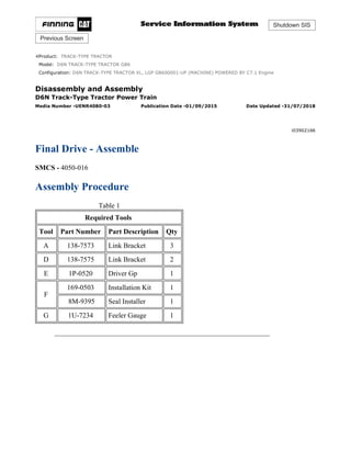
1. Shutdown SIS
Previous Screen
Product: TRACK-TYPE TRACTOR
Model: D6N TRACK-TYPE TRACTOR GB6
Configuration: D6N TRACK-TYPE TRACTOR XL, LGP GB600001-UP (MACHINE) POWERED BY C7.1 Engine
Disassembly and Assembly
D6N Track-Type Tractor Power Train
Media Number -UENR4080-03 Publication Date -01/09/2015 Date Updated -31/07/2018
i03902166
Final Drive - Assemble
SMCS - 4050-016
Assembly Procedure
Table 1
Required Tools
Tool Part Number Part Description Qty
A 138-7573 Link Bracket 3
D 138-7575 Link Bracket 2
E 1P-0520 Driver Gp 1
F
169-0503 Installation Kit 1
8M-9395 Seal Installer 1
G 1U-7234 Feeler Gauge 1
1/7
D6N TRACK-TYPE TRACTOR XL, LGP GB600001-UP (MACHINE) POWERED ...
2021/10/20
https://127.0.0.1/sisweb/sisweb/techdoc/techdoc_print_page.jsp?returnurl=/sis...
2. Illustration 1 g01235241
1. Raise the temperature of bearing cone (21). Install bearing cone (21) onto spindle (23).
2. Use Tooling (F) (not shown) in order to install Duo-cone seal (22). Refer to Disassembly
and Assembly, "Duo-Cone Conventional Seals - Install".
Illustration 2 g01235238
3. Lower the temperature of bearing cups (19) and (18).
4. Install bearing cups (19) and (18) in hub (3).
5. Use Tooling (F) (not shown) in order to install Duo-cone seal (20) in hub (3). Refer to
Disassembly and Assembly, "Duo-Cone Conventional Seals - Install".
2/7
D6N TRACK-TYPE TRACTOR XL, LGP GB600001-UP (MACHINE) POWERED ...
2021/10/20
https://127.0.0.1/sisweb/sisweb/techdoc/techdoc_print_page.jsp?returnurl=/sis...
3. Illustration 3 g01235181
6. Install Tooling (D) and a suitable lifting device to hub (3). Install hub (3) onto the spindle.
The weight of hub (3) is approximately 135 kg (298 lb).
Illustration 4 g00990323
7. Install lip seal (16) and sleeve bearing (15).
3/7
D6N TRACK-TYPE TRACTOR XL, LGP GB600001-UP (MACHINE) POWERED ...
2021/10/20
https://127.0.0.1/sisweb/sisweb/techdoc/techdoc_print_page.jsp?returnurl=/sis...
5. Illustration 6 g02145273
9. Raise the temperature of bearing cone (17). Install bearing cone (17) on the spindle.
10. Install hub (12) and gear (13) as an assembly.
11. Install retainer (11) and bolts (10). Tighten all bolts (10) in a star pattern. Tighten bolts (10)
to a torque of 120 ± 20 N·m (89 ± 15 lb ft). Continually rotate hub (12) in order to properly
seat bearing cone (17). Tighten bolts (10) to a torque of 120 ± 20 N·m (89 ± 15 lb ft) in
order to ensure the proper torque.
12. Use Tooling (G) (not shown) in order to verify that the spindle is touching the retainer.
13. If necessary, repeat Step 11 and Step 12 in order to verify that bearing cone (17) is seated
properly.
5/7
D6N TRACK-TYPE TRACTOR XL, LGP GB600001-UP (MACHINE) POWERED ...
2021/10/20
https://127.0.0.1/sisweb/sisweb/techdoc/techdoc_print_page.jsp?returnurl=/sis...
6. Illustration 7 g01234812
14. Lower the temperature of bearing cups (7). Install bearing cups (7) into gear (8).
15. Position bearing cones (6) and (9) into gear (8).
16. Position gear (8) into carrier (1).
Illustration 8 g01235164
17. Lower the temperature of shaft (5). Use a suitable press in order to install shaft (5). Install
shaft (5) until the end of the shaft is flush with the outer surface of carrier (1).
18. Install bolt (4) and the plate to carrier (1).
19. Verify that there is metal to metal contact between plates (4) and the shafts.
6/7
D6N TRACK-TYPE TRACTOR XL, LGP GB600001-UP (MACHINE) POWERED ...
2021/10/20
https://127.0.0.1/sisweb/sisweb/techdoc/techdoc_print_page.jsp?returnurl=/sis...
7. 20. Repeat Steps 17 through 19 for the remaining shafts.
Illustration 9 g01234745
21. Attach Tooling (A) to carrier (1). Position carrier (1) into hub (3). The weight of carrier (1)
is approximately 41 kg (90 lb).
22. Install bolts (2).
23. Remove Tooling (A).
End By:
a. Install the final drive. Refer to Disassembly and Assembly, "Final Drive - Install".
Copyright 1993 - 2021 Caterpillar Inc.
All Rights Reserved.
Private Network For SIS Licensees.
Wed Oct 20 09:20:28 UTC+0800 2021
7/7
D6N TRACK-TYPE TRACTOR XL, LGP GB600001-UP (MACHINE) POWERED ...
2021/10/20
https://127.0.0.1/sisweb/sisweb/techdoc/techdoc_print_page.jsp?returnurl=/sis...
8. Shutdown SIS
Previous Screen
Product: TRACK-TYPE TRACTOR
Model: D6N TRACK-TYPE TRACTOR GB6
Configuration: D6N TRACK-TYPE TRACTOR XL, LGP GB600001-UP (MACHINE) POWERED BY C7.1 Engine
Disassembly and Assembly
D6N Track-Type Tractor Power Train
Media Number -UENR4080-03 Publication Date -01/09/2015 Date Updated -31/07/2018
i06740931
Final Drive, Steering Differential, and Brake (Left Side) -
Remove and Install
SMCS - 4050-010-LT; 4132-010-LT
Removal Procedure
Table 1
Required Tools
Tool Part Number Part Description Qty
A 154-6181 Forcing Screw 3
B 439-3940 Bracket As 1
C 142-1664 Lifting Bracket Gp 1
D 8S-9906 Ratchet Puller 1
Start By:
a. Separate the track.
b. Remove the steering motor.
c. Remove the axles.
Personal injury can result from hydraulic oil pressure and hot oil.
1/5
D6N TRACK-TYPE TRACTOR XL, LGP GB600001-UP (MACHINE) POWERED ...
2021/10/20
https://127.0.0.1/sisweb/sisweb/techdoc/techdoc_print_page.jsp?returnurl=/sis...
9. Hydraulic oil pressure can remain in the hydraulic system after the
engine has been stopped. Serious injury can be caused if this pressure is
not released before any service is done on the hydraulic system.
Make sure all of the work tools have been lowered to the ground, and
the oil is cool before removing any components or lines. Remove the oil
filler cap only when the engine is stopped, and the filler cap is cool
enough to touch with your bare hand.
Illustration 1 g00992346
1. Remove bolts (1).
Illustration 2 g00992348
2. Install Tooling (A) and remove adapter (2).
2/5
D6N TRACK-TYPE TRACTOR XL, LGP GB600001-UP (MACHINE) POWERED ...
2021/10/20
https://127.0.0.1/sisweb/sisweb/techdoc/techdoc_print_page.jsp?returnurl=/sis...
10. Illustration 3 g00992349
3. Remove two bolts (3) and bolt (4) to install Tooling (B). Remove two bolts (5).
Illustration 4 g00865077
4. Remove bolts (6) and the nuts from the top of the sprocket segment.
5. Attach Tooling (C) and a suitable lifting device to the final drive, steering differential, and
brake (left side). The weight of the final drive, steering differential, and brake (left side) is
approximately 680 kg (1500 lb).
Illustration 5 g00992350
3/5
D6N TRACK-TYPE TRACTOR XL, LGP GB600001-UP (MACHINE) POWERED ...
2021/10/20
https://127.0.0.1/sisweb/sisweb/techdoc/techdoc_print_page.jsp?returnurl=/sis...
11. 6. Remove remaining bolts (3) and the washers.
Illustration 6 g06101043
7. Attach Tooling (D) to Tooling (B) and Tooling (C).
8. Separate the final drive approximately 152 mm (6.0 inch).
9. Release the pressure on Tooling (D). Rotate the brake housing 90 degrees in the
counterclockwise direction.
Illustration 7 g00992352
10. Rotating the brake housing allows pinion (7) to point forward. Rotating the brake housing
will allow the final drive to swing toward the front of the machine. Rotating the brake
housing will allow clearance for the ring gear to clear the machine. Remove the final drive,
steering differential, and brake (left side).
Installation Procedure
1. Install the final drive, steering differential, and brake (left side) in the reverse order of
removal.
a. Apply SAE 30W lubricant to the threads of bolts (6). Tighten bolts (6) to a torque of
175 ± 40 N·m (129 ± 30 lb ft). Then, tighten bolts (6) by an extra 1/3 turn. The final
torque of bolts (6) should be a minimum of 380 N·m (280 lb ft).
4/5
D6N TRACK-TYPE TRACTOR XL, LGP GB600001-UP (MACHINE) POWERED ...
2021/10/20
https://127.0.0.1/sisweb/sisweb/techdoc/techdoc_print_page.jsp?returnurl=/sis...
12. Copyright 1993 - 2021 Caterpillar Inc.
All Rights Reserved.
Private Network For SIS Licensees.
Wed Oct 20 09:21:24 UTC+0800 2021
5/5
D6N TRACK-TYPE TRACTOR XL, LGP GB600001-UP (MACHINE) POWERED ...
2021/10/20
https://127.0.0.1/sisweb/sisweb/techdoc/techdoc_print_page.jsp?returnurl=/sis...
13. Shutdown SIS
Previous Screen
Product: TRACK-TYPE TRACTOR
Model: D6N TRACK-TYPE TRACTOR GB6
Configuration: D6N TRACK-TYPE TRACTOR XL, LGP GB600001-UP (MACHINE) POWERED BY C7.1 Engine
Disassembly and Assembly
D6N Track-Type Tractor Power Train
Media Number -UENR4080-03 Publication Date -01/09/2015 Date Updated -31/07/2018
i06983856
Steering Differential and Brake - Disassemble
SMCS - 4131-015
Disassembly Procedure
Table 1
Required Tools
Tool Part Number Description Qty
A 138-7573 Link Bracket 2
B 3K-4897 Spring Pin 8
C 6V-4072 Spanner Wrench 1
D
9S-9154 Step Plate 1
6V-3009 Bar 1
8S-6470 Forcing Screw 1
8S-5133 Plug 1
5P-8245 Washer 4
1D-4719 Full Nut 2
2H-6488 Bolt 2
E 9S-9154 Step Plate 1
6V-3009 Bar 1
8S-6470 Forcing Screw 1
8S-5133 Plug 1
5P-8245 Washer 4
1/22
D6N TRACK-TYPE TRACTOR XL, LGP GB600001-UP (MACHINE) POWERED ...
2021/10/20
https://127.0.0.1/sisweb/sisweb/techdoc/techdoc_print_page.jsp?returnurl=/sis...
14. 1D-4719 Full Nut 2
1D-4574 Bolt 2
8H-0663 Bearing Puller 1
F 138-7575 Link Bracket 3
G
8B-7550 Leg 2
8B-7559 Adapter 2
3H-0465 Plate 4
1P-0498 Plate 1
1B-4207 Full Nut 2
5H-9976 Screw 1
5B-0637 High Idle Nut 1
8H-0684 Ratchet Wrench 1
8B-7563 Handle 1
5F-7353 Washer 1
8B-7548 Push-Puller Tool Gp 1
Start By:
a. Remove the left final drive, the steering differential, and the brake. Refer to Disassembly
and Assembly, "Final Drive, Steering Differential, and Brake (Left Side) - Remove"
.
2/22
D6N TRACK-TYPE TRACTOR XL, LGP GB600001-UP (MACHINE) POWERED ...
2021/10/20
https://127.0.0.1/sisweb/sisweb/techdoc/techdoc_print_page.jsp?returnurl=/sis...
15. Illustration 1 g00993890
1. Remove bolts (1) and the washers.
2. Remove two opposite bolts (2).
3/22
D6N TRACK-TYPE TRACTOR XL, LGP GB600001-UP (MACHINE) POWERED ...
2021/10/20
https://127.0.0.1/sisweb/sisweb/techdoc/techdoc_print_page.jsp?returnurl=/sis...
16. Illustration 2 g00823691
3. Install Tooling (A) and a suitable lifting device.
4. Remove sliding carrier (3). The weight of sliding carrier (3) is approximately 48 kg
(105 lb).
5. Remove Tooling (A).
4/22
D6N TRACK-TYPE TRACTOR XL, LGP GB600001-UP (MACHINE) POWERED ...
2021/10/20
https://127.0.0.1/sisweb/sisweb/techdoc/techdoc_print_page.jsp?returnurl=/sis...
17. Illustration 3 g06187075
6. Remove remaining bolts (2) and slinger (4) from planetary carrier (7).
7. Remove retaining ring (5), thrust ring (5A), and planetary carrier (7) from ring gear (6).
Illustration 4 g00823775
8. Remove O-ring seal (10) from planetary carrier (7).
9. Use a hammer and a punch to push pin (12) in shaft (11).
10. Remove shaft (11), planetary gear (9), discs (8), and bearing (13) from planetary carrier (7).
11. Remove pin (12) from shaft (11).
12. Repeat Steps 9 through 11 for the remaining planetary gears.
5/22
D6N TRACK-TYPE TRACTOR XL, LGP GB600001-UP (MACHINE) POWERED ...
2021/10/20
https://127.0.0.1/sisweb/sisweb/techdoc/techdoc_print_page.jsp?returnurl=/sis...
18. Illustration 5 g00823759
13. Remove lockring (14) and remove retaining ring (16).
14. Remove sun gear (15) from planetary carrier (18).
15. Remove spacer (17).
6/22
D6N TRACK-TYPE TRACTOR XL, LGP GB600001-UP (MACHINE) POWERED ...
2021/10/20
https://127.0.0.1/sisweb/sisweb/techdoc/techdoc_print_page.jsp?returnurl=/sis...
19. Illustration 6 g00995126
16. Remove bolts (19), plate (20), and gear (21) from planetary carrier (18).
17. Use Tooling (B) to compress the retaining ring that holds planetary carrier (18) in ring gear
(6).
18. Separate planetary carrier (18) from ring gear (6).
19. Remove the retaining ring from planetary carrier (18).
20. Use a hammer and a punch to push pin (23) in shaft (24).
7/22
D6N TRACK-TYPE TRACTOR XL, LGP GB600001-UP (MACHINE) POWERED ...
2021/10/20
https://127.0.0.1/sisweb/sisweb/techdoc/techdoc_print_page.jsp?returnurl=/sis...
20. Illustration 7 g00823872
21. Remove shaft (24), planetary gear (22), discs (26), and bearing (25) from planetary carrier
(18).
22. Remove pin (23) from shaft (24).
23. Repeat Steps 20 through 22 for the remaining planetary gears.
8/22
D6N TRACK-TYPE TRACTOR XL, LGP GB600001-UP (MACHINE) POWERED ...
2021/10/20
https://127.0.0.1/sisweb/sisweb/techdoc/techdoc_print_page.jsp?returnurl=/sis...
21. Illustration 8 g00823878
24. Place a bolt in the teeth of pinion gear (27) to prevent movement.
9/22
D6N TRACK-TYPE TRACTOR XL, LGP GB600001-UP (MACHINE) POWERED ...
2021/10/20
https://127.0.0.1/sisweb/sisweb/techdoc/techdoc_print_page.jsp?returnurl=/sis...
22. Illustration 9 g00823884
25. Bend the tang on lock washer (29) away from nut (28).
26. Use Tooling (C) to remove nut (28) from the pinion.
27. Remove lockwasher (29) and washer (30) from the pinion.
28. Remove bolts (32).
29. Remove carrier (31) from the support bracket.
10/22
D6N TRACK-TYPE TRACTOR XL, LGP GB600001-UP (MACHINE) POWERE...
2021/10/20
https://127.0.0.1/sisweb/sisweb/techdoc/techdoc_print_page.jsp?returnurl=/sis...
23. Illustration 10 g00823890
30. Use Tooling (D) to force pinion (27) from bearing cone (33) and carrier (31).
11/22
D6N TRACK-TYPE TRACTOR XL, LGP GB600001-UP (MACHINE) POWERE...
2021/10/20
https://127.0.0.1/sisweb/sisweb/techdoc/techdoc_print_page.jsp?returnurl=/sis...
24. Illustration 11 g00824243
31. Use Tooling (E) to remove bearing cone (34) from pinion (27).
12/22
D6N TRACK-TYPE TRACTOR XL, LGP GB600001-UP (MACHINE) POWERE...
2021/10/20
https://127.0.0.1/sisweb/sisweb/techdoc/techdoc_print_page.jsp?returnurl=/sis...
26. Illustration 13 g00824265
33. Remove bolts (36).
34. Remove support bracket (37) and shims (38) from the housing.
35. Remove bolts (39).
36. Remove bevel gear (40) from housing (41).
14/22
D6N TRACK-TYPE TRACTOR XL, LGP GB600001-UP (MACHINE) POWERE...
2021/10/20
https://127.0.0.1/sisweb/sisweb/techdoc/techdoc_print_page.jsp?returnurl=/sis...
27. Illustration 14 g00824268
37. Attach Tooling (F) and a suitable lifting device to brake housing (42).
Personal injury can result from parts and/or covers under spring
pressure.
Spring force will be released when covers are removed.
Be prepared to hold spring loaded covers as the bolts are loosened.
38. Remove bolts (43).
39. Remove brake housing (42) from the final drive housing (44). The weight of brake housing
(42) is approximately 150 kg (335 lb).
15/22
D6N TRACK-TYPE TRACTOR XL, LGP GB600001-UP (MACHINE) POWERE...
2021/10/20
https://127.0.0.1/sisweb/sisweb/techdoc/techdoc_print_page.jsp?returnurl=/sis...
29. Illustration 16 g00824349
40. Remove bolts and washers (45).
41. Remove retainer (46) and thrust washer (47).
42. Remove hub (48), the friction discs, and brake plates (49).
43. If necessary, remove ring (50) from hub (48).
44. Remove thrust washer (51).
Personal injury can result from parts and/or covers under spring
pressure.
Spring force will be released when covers are removed.
Be prepared to hold spring loaded covers as the bolts are loosened.
17/22
D6N TRACK-TYPE TRACTOR XL, LGP GB600001-UP (MACHINE) POWERE...
2021/10/20
https://127.0.0.1/sisweb/sisweb/techdoc/techdoc_print_page.jsp?returnurl=/sis...
30. Suggest:
If the above button click is invalid.
Please download this document
first, and then click the above link
to download the complete manual.
Thank you so much for reading
31. Illustration 17 g00824351
45. Remove bolts (52) slowly.
46. Remove retainer (53), ring (54), and O-ring seal (55) from brake housing (42).
18/22
D6N TRACK-TYPE TRACTOR XL, LGP GB600001-UP (MACHINE) POWERE...
2021/10/20
https://127.0.0.1/sisweb/sisweb/techdoc/techdoc_print_page.jsp?returnurl=/sis...