
Recommended
More Related Content
Similar to Caterpillar Cat 990K Wheel Loader (Prefix A9P) Service Repair Manual (A9P00001 and up).pdf
Similar to Caterpillar Cat 990K Wheel Loader (Prefix A9P) Service Repair Manual (A9P00001 and up).pdf (15)
More from fjkskkedmm4r
More from fjkskkedmm4r (20)
Recently uploaded
Recently uploaded (20)
Caterpillar Cat 990K Wheel Loader (Prefix A9P) Service Repair Manual (A9P00001 and up).pdf
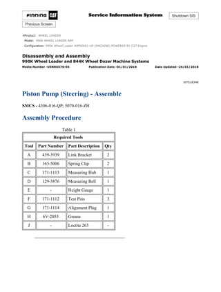
- 1. Shutdown SIS Previous Screen Product: WHEEL LOADER Model: 990K WHEEL LOADER A9P Configuration: 990K Wheel Loader A9P00001-UP (MACHINE) POWERED BY C27 Engine Disassembly and Assembly 990K Wheel Loader and 844K Wheel Dozer Machine Systems Media Number -UENR6576-05 Publication Date -01/01/2018 Date Updated -26/01/2018 i07518348 Piston Pump (Steering) - Assemble SMCS - 4306-016-QP; 5070-016-ZH Assembly Procedure Table 1 Required Tools Tool Part Number Part Description Qty A 439-3939 Link Bracket 2 B 163-5006 Spring Clip 2 C 171-1113 Measuring Hub 1 D 129-3876 Measuring Bell 1 E - Height Gauge 1 F 171-1112 Test Pins 3 G 171-1114 Alignment Plug 1 H 6V-2055 Grease 1 J - Loctite 263 - 1/16 990K Wheel Loader A9P00001-UP (MACHINE) POWERED BY C27 Engine(SEBP6... 2021/11/23 https://127.0.0.1/sisweb/sisweb/techdoc/techdoc_print_page.jsp?returnurl=/sis...
- 2. Illustration 1 g06152922 1. Install retaining ring (61) and bearing (62) onto shaft assembly (60). Illustration 2 g06153863 2. Use a soft faced hammer to install shaft (60) into housing (30). Illustration 3 g06153868 2/16 990K Wheel Loader A9P00001-UP (MACHINE) POWERED BY C27 Engine(SEBP6... 2021/11/23 https://127.0.0.1/sisweb/sisweb/techdoc/techdoc_print_page.jsp?returnurl=/sis...
- 3. Illustration 4 g06153871 Note the orientation of lip seals (59). 3. Install lip seals (59) and the O-ring seals and into cover (58). Illustration 5 g06153874 4. Install cover (58) and bolts (57). Illustration 6 g06146430 5. Install outer races (56) into housing (30). 3/16 990K Wheel Loader A9P00001-UP (MACHINE) POWERED BY C27 Engine(SEBP6... 2021/11/23 https://127.0.0.1/sisweb/sisweb/techdoc/techdoc_print_page.jsp?returnurl=/sis...
- 4. Illustration 7 g06153879 6. Install pins (54) onto swashplate (53). Illustration 8 g06153884 Illustration 9 g06153889 4/16 990K Wheel Loader A9P00001-UP (MACHINE) POWERED BY C27 Engine(SEBP6... 2021/11/23 https://127.0.0.1/sisweb/sisweb/techdoc/techdoc_print_page.jsp?returnurl=/sis...
- 5. 7. Install bearings (55) to swashplate (53). Use Tooling (B) to hold the bearings in place for installation. 8. Install swashplate (53) and remove Tooling (B). Illustration 10 g06153892 9. Install retainers (51), plugs (52) and the O-rings. Repeat for opposite side. Note: Ensure retainers (51) lock into pins (54) shown in illustration 7.. Illustration 11 g06153894 10. Install adjustment screw (50) into housing (30). Repeat for opposite side. 5/16 990K Wheel Loader A9P00001-UP (MACHINE) POWERED BY C27 Engine(SEBP6... 2021/11/23 https://127.0.0.1/sisweb/sisweb/techdoc/techdoc_print_page.jsp?returnurl=/sis...
- 6. Illustration 12 g06153856 11. Place port plate (31) on a flat surface and install Tooling (G). Illustration 13 g06149897 12. Install Tooling (F) into bearing (49). Illustration 14 g06149905 13. Install shims (47) into bearing (49). Illustration 15 g06149911 6/16 990K Wheel Loader A9P00001-UP (MACHINE) POWERED BY C27 Engine(SEBP6... 2021/11/23 https://127.0.0.1/sisweb/sisweb/techdoc/techdoc_print_page.jsp?returnurl=/sis...
- 7. 14. Install bearing (49) onto barrel (44). Illustration 16 g06153902 Dimension (X) is 220.95 - 221.20mm (8.698 - 8.708 inch) Dimension (Y) is 170.95 - 171.20mm (6.730- 6.740 inch) 15. Install barrel assembly (44) onto port plate (31). Install retainer plate (46) onto barrel assembly (44). Install Tooling (C) and (D) onto retainer plate (46). 16. Use Tooling (G) to measure dimensions (X) and (Y). Adjust the shims under retainer plate (46) as necessary to achieve the dimensions shown in Illustration 16. 17. Remove Tooling (C) and (D). Remove retainer plate (46) from barrel assembly (44). Remove barrel assembly (44) from port plate (31). Illustration 17 g06149911 18. Remove bearing (49) from barrel (44). 7/16 990K Wheel Loader A9P00001-UP (MACHINE) POWERED BY C27 Engine(SEBP6... 2021/11/23 https://127.0.0.1/sisweb/sisweb/techdoc/techdoc_print_page.jsp?returnurl=/sis...
- 8. Illustration 18 g06149905 19. Remove shims (47) from bearing (49). Illustration 19 g06149897 20. Remove Tooling (F) from bearing (49). Illustration 20 g06149972 8/16 990K Wheel Loader A9P00001-UP (MACHINE) POWERED BY C27 Engine(SEBP6... 2021/11/23 https://127.0.0.1/sisweb/sisweb/techdoc/techdoc_print_page.jsp?returnurl=/sis...
- 9. Illustration 21 g06149905 21. Apply Tooling (H) to springs (48). Install springs (48) and shims (47) into bearing (49). Illustration 22 g06149911 22. Install bearing (49) onto barrel (44). Illustration 23 g06146401 23. Install retainer plate (46) and pistons (45) into barrel (44). 9/16 990K Wheel Loader A9P00001-UP (MACHINE) POWERED BY C27 Engine(SEBP6... 2021/11/23 https://127.0.0.1/sisweb/sisweb/techdoc/techdoc_print_page.jsp?returnurl=/sis...
- 10. Illustration 24 g06146790 24. Rotate housing (30) to a horizontal position. Use a suitable string to install barrel assembly (44) into housing (30). Illustration 25 g06146314 25. Apply Tooling (J) to bolts (42). Install retainer (43) and bolts (42). Repeat for opposite side. Note: Bolts (42) should be replaced with new bolts. Illustration 26 g06146295 26. Install cover (41). Repeat for opposite side. 10/16 990K Wheel Loader A9P00001-UP (MACHINE) POWERED BY C27 Engine(SEB... 2021/11/23 https://127.0.0.1/sisweb/sisweb/techdoc/techdoc_print_page.jsp?returnurl=/sis...
- 11. Illustration 27 g06154614 Illustration 28 g06154626 27. Install O-ring seal (39). Install rods (40) and (38). Install piston (37), spring (36), spring (35), and piston (34). Illustration 29 g06153915 28. Install bushing (33) and bearing (32) into head (29). Apply Tooling (H) to port plate (31) and install into head (29). 11/16 990K Wheel Loader A9P00001-UP (MACHINE) POWERED BY C27 Engine(SEB... 2021/11/23 https://127.0.0.1/sisweb/sisweb/techdoc/techdoc_print_page.jsp?returnurl=/sis...
- 12. Illustration 30 g06146219 Improper assembly of parts that are spring loaded can cause bodily injury. To prevent possible injury, follow the established assembly procedure and wear protective equipment. 29. Attach Tooling (B) and a suitable lifting device to head (29). Install head (29) onto housing (30). Illustration 31 g06146174 30. Install bolts (28). Tighten bolts (28) to a torque of 780 ± 78 N·m (575 ± 58 lb ft). Install plug (27) and the O-ring seal. Tighten plug (27) to a torque of 198 ± 20 N·m (146 ± 15 lb ft). 12/16 990K Wheel Loader A9P00001-UP (MACHINE) POWERED BY C27 Engine(SEB... 2021/11/23 https://127.0.0.1/sisweb/sisweb/techdoc/techdoc_print_page.jsp?returnurl=/sis...
- 13. Illustration 32 g06146164 Illustration 33 g06146158 31. Install plugs (26), (25), and the O-ring seals. Illustration 34 g06153150 32. Install retaining ring (24A). 13/16 990K Wheel Loader A9P00001-UP (MACHINE) POWERED BY C27 Engine(SEB... 2021/11/23 https://127.0.0.1/sisweb/sisweb/techdoc/techdoc_print_page.jsp?returnurl=/sis...
- 14. Illustration 35 g06153932 33. Install impeller (23) and retaining ring (24). Illustration 36 g06145926 34. Install adapter (22) and the O-ring seal. Install bolts (21). Illustration 37 g06145925 35. Install adapter (20) and the O-ring seal. Install bolts (19). Install coupler (18). 14/16 990K Wheel Loader A9P00001-UP (MACHINE) POWERED BY C27 Engine(SEB... 2021/11/23 https://127.0.0.1/sisweb/sisweb/techdoc/techdoc_print_page.jsp?returnurl=/sis...
- 15. Illustration 38 g06145907 Improper assembly of parts that are spring loaded can cause bodily injury. To prevent possible injury, follow the established assembly procedure and wear protective equipment. 36. Install spool (11), guide (12), spring (13), spring (14), guide (15), O-ring seal (16), and valve (17). 37. Install spool (5), guide (6), spring (7), guide (8), O-ring seal (9), and valve (10). Illustration 39 g06145896 38. Install O-ring seals (4). 15/16 990K Wheel Loader A9P00001-UP (MACHINE) POWERED BY C27 Engine(SEB... 2021/11/23 https://127.0.0.1/sisweb/sisweb/techdoc/techdoc_print_page.jsp?returnurl=/sis...
- 16. Illustration 40 g06145891 39. Install valve (2) and bolts (3). Illustration 41 g06145889 40. Install plug (1) and the O-ring seal. Remove the piston pump from Tooling (A). End By: a. Install the piston pump. Copyright 1993 - 2021 Caterpillar Inc. All Rights Reserved. Private Network For SIS Licensees. Tue Nov 23 17:33:33 UTC+0800 2021 16/16 990K Wheel Loader A9P00001-UP (MACHINE) POWERED BY C27 Engine(SEB... 2021/11/23 https://127.0.0.1/sisweb/sisweb/techdoc/techdoc_print_page.jsp?returnurl=/sis...
- 17. Shutdown SIS Previous Screen Product: WHEEL LOADER Model: 990K WHEEL LOADER A9P Configuration: 990K Wheel Loader A9P00001-UP (MACHINE) POWERED BY C27 Engine Disassembly and Assembly 990K Wheel Loader and 844K Wheel Dozer Machine Systems Media Number -UENR6576-05 Publication Date -01/01/2018 Date Updated -26/01/2018 i06545830 Gear Pump (Secondary Steering) - Remove and Install SMCS - 4324-010-GT; 4324-010; 5073-010-SST; 5073-010 Removal Procedure Start by: a. Connect the steering frame lock. b. Release the hydraulic system pressure. NOTICE Care must be taken to ensure that fluids are contained during performance of inspection, maintenance, testing, adjusting, and repair of the product. Be prepared to collect the fluid with suitable containers before opening any compartment or disassembling any component containing fluids. Refer to Special Publication, NENG2500, "Dealer Service Tool Catalog" for tools and supplies suitable to collect and contain fluids on Cat® products. Dispose of all fluids according to local regulations and mandates. Hot oil and hot components can cause personal injury. Do not allow hot oil or hot components to contact skin. 1/3 990K Wheel Loader A9P00001-UP (MACHINE) POWERED BY C27 Engine(SEBP6... 2021/11/23 https://127.0.0.1/sisweb/sisweb/techdoc/techdoc_print_page.jsp?returnurl=/sis...
- 18. Note: Check the O-ring seals, the gaskets, and the seals for wear or for damage. Replace the components, if necessary. Note: Cleanliness is an important factor. Before assembly, thoroughly clean all parts in cleaning fluid. Allow the parts to air dry. Do not use wiping cloths or rags to dry parts. Lint may be deposited on the parts which may cause trouble. Inspect all parts. If any parts are worn or damaged, use new parts for replacement. Dirt and other contaminants can damage the precision component. Perform assembly procedures on a clean work surface. Keep components covered and protected always. 1. Drain the transmission oil into a suitable container for storage or disposal. Refer to Operation and Maintenance Manual, "Transmission Oil - Change". Drain enough oil to bring the oil level below the secondary steering pump. Illustration 1 g00346175 2. Disconnect hose assemblies (2) from secondary steering pump (3). Illustration 2 g00346174 3. Remove nuts (4) and secondary steering pump (3). 2/3 990K Wheel Loader A9P00001-UP (MACHINE) POWERED BY C27 Engine(SEBP6... 2021/11/23 https://127.0.0.1/sisweb/sisweb/techdoc/techdoc_print_page.jsp?returnurl=/sis...
- 19. Illustration 3 g00346176 4. Remove gasket (5) from the pump drive. Installation Procedure 1. Install secondary steering pump (3) in the reverse order of removal. Copyright 1993 - 2021 Caterpillar Inc. All Rights Reserved. Private Network For SIS Licensees. Tue Nov 23 17:34:30 UTC+0800 2021 3/3 990K Wheel Loader A9P00001-UP (MACHINE) POWERED BY C27 Engine(SEBP6... 2021/11/23 https://127.0.0.1/sisweb/sisweb/techdoc/techdoc_print_page.jsp?returnurl=/sis...
- 20. Shutdown SIS Previous Screen Product: WHEEL LOADER Model: 990K WHEEL LOADER A9P Configuration: 990K Wheel Loader A9P00001-UP (MACHINE) POWERED BY C27 Engine Disassembly and Assembly 990K Wheel Loader and 844K Wheel Dozer Machine Systems Media Number -UENR6576-05 Publication Date -01/01/2018 Date Updated -26/01/2018 i00761547 Gear Pump (Secondary Steering) - Disassemble SMCS - 4324-015-GT; 5073-015-SST Disassembly Procedure Start By: a. Remove the secondary steering pump. Refer to Disassembly and Assembly, "Gear Pump (Secondary Steering) - Remove". Illustration 1 g00346187 1. Remove bolts (1) and the washers. Remove body (2) from the secondary steering pump. 1/7 990K Wheel Loader A9P00001-UP (MACHINE) POWERED BY C27 Engine(SEBP6... 2021/11/23 https://127.0.0.1/sisweb/sisweb/techdoc/techdoc_print_page.jsp?returnurl=/sis...
- 21. Illustration 2 g00346188 2. Remove two pistons (3) and two springs from body (2). 3. Remove two seals (4) from body (2). Illustration 3 g00346189 4. Remove spacer (5) from body assembly (6). Illustration 4 g00346190 5. Remove two spacers (7) from spacer (5). 2/7 990K Wheel Loader A9P00001-UP (MACHINE) POWERED BY C27 Engine(SEBP6... 2021/11/23 https://127.0.0.1/sisweb/sisweb/techdoc/techdoc_print_page.jsp?returnurl=/sis...
- 22. Illustration 5 g00346191 6. Remove two pistons (8) and two springs (9) from body assembly (6). Illustration 6 g00346232 7. Remove two seals (10) from body assembly (6). Illustration 7 g00346233 8. Remove bolts (11) and the washers from flange assembly (12). Remove flange assembly (12) from body assembly (6). 3/7 990K Wheel Loader A9P00001-UP (MACHINE) POWERED BY C27 Engine(SEBP6... 2021/11/23 https://127.0.0.1/sisweb/sisweb/techdoc/techdoc_print_page.jsp?returnurl=/sis...
- 23. Illustration 8 g00346234 9. Remove seal (13) from flange assembly (12). Illustration 9 g00346235 10. Remove seals (14) from bushings (15). Illustration 10 g00346236 11. Remove two dowels (16) and two bushings (15) from flange assembly (12). 4/7 990K Wheel Loader A9P00001-UP (MACHINE) POWERED BY C27 Engine(SEBP6... 2021/11/23 https://127.0.0.1/sisweb/sisweb/techdoc/techdoc_print_page.jsp?returnurl=/sis...
- 24. Illustration 11 g00346237 12. Remove two lip seals (17) and the ring from flange assembly (12). Illustration 12 g00346239 Illustration 13 g00346240 13. Remove two metal seals (18) and five plastic seals (19) from body assembly (6). 5/7 990K Wheel Loader A9P00001-UP (MACHINE) POWERED BY C27 Engine(SEBP6... 2021/11/23 https://127.0.0.1/sisweb/sisweb/techdoc/techdoc_print_page.jsp?returnurl=/sis...
- 25. Please write to us. Our email: aservicemanualpdf@yahoo.com Please go to the homepage to get the full manual, or other brand PDF manuals. Home Site: aservicemanualpdf.com
- 26. Thank you very much for your reading. Please Click Here. Then Get COMPLETE MANUAL. NO WAITING NOTE: If there is no response to click on the link above, please download the PDF document first and then click on it. GET MORE OTHER MANUALS https://www.aservicemanualpdf.com/ GET MORE OTHER MANUALS https://www.aservicemanualpdf.com/
- 27. Illustration 14 g00346241 14. Remove plate (20) from body assembly (6). Illustration 15 g00346242 15. Remove shaft (21) and gear (22) from body assembly (6). Illustration 16 g00346243 16. Remove plate (23) from body assembly (6). 6/7 990K Wheel Loader A9P00001-UP (MACHINE) POWERED BY C27 Engine(SEBP6... 2021/11/23 https://127.0.0.1/sisweb/sisweb/techdoc/techdoc_print_page.jsp?returnurl=/sis...
- 28. Illustration 17 g00346244 Illustration 18 g00346245 17. Remove two metal seals (24) and five plastic seals (25) from body assembly (6). Illustration 19 g00346246 18. Remove seals (26) from bushings (27). Remove bushings (27). Copyright 1993 - 2021 Caterpillar Inc. All Rights Reserved. Private Network For SIS Licensees. Tue Nov 23 17:35:27 UTC+0800 2021 7/7 990K Wheel Loader A9P00001-UP (MACHINE) POWERED BY C27 Engine(SEBP6... 2021/11/23 https://127.0.0.1/sisweb/sisweb/techdoc/techdoc_print_page.jsp?returnurl=/sis...
- 29. Shutdown SIS Previous Screen Product: WHEEL LOADER Model: 990K WHEEL LOADER A9P Configuration: 990K Wheel Loader A9P00001-UP (MACHINE) POWERED BY C27 Engine Disassembly and Assembly 990K Wheel Loader and 844K Wheel Dozer Machine Systems Media Number -UENR6576-05 Publication Date -01/01/2018 Date Updated -26/01/2018 i01281269 Gear Pump (Secondary Steering) - Assemble SMCS - 4324-016-GT; 5073-016-SST Assembly Procedure Table 1 Required Tools Tool Part Number Part Description Qty A 1P-0510 Driver Gp 1 Note: Thoroughly clean all parts of the secondary steering pump prior to assembly. 1. Check the condition of all seals. If any seals are worn or damaged, use new parts for replacement . Lubricate the seals with clean hydraulic oil. 2. Apply clean hydraulic oil on all internal parts of the secondary steering pump. NOTICE Failure to follow the recommended procedure or the specified tooling that is required for the procedure could result in damage to components. To avoid component damage, follow the recommended procedure using the recommended tools. Note: Two isolation plates are required for the bottom of the pump housing. Two isolation plates are required for the top of the pump housing. The isolation plates hold the seal components together. The isolation plates that have round edges on one outer radius will be 1/8 990K Wheel Loader A9P00001-UP (MACHINE) POWERED BY C27 Engine(SEBP6... 2021/11/23 https://127.0.0.1/sisweb/sisweb/techdoc/techdoc_print_page.jsp?returnurl=/sis...