Why Is Your BMW X3 Hood Not Responding To Release CommandsDart Auto
Experiencing difficulty opening your BMW X3's hood? This guide explores potential issues like mechanical obstruction, hood release mechanism failure, electrical problems, and emergency release malfunctions. Troubleshooting tips include basic checks, clearing obstructions, applying pressure, and using the emergency release.
In this presentation, we have discussed a very important feature of BMW X5 cars… the Comfort Access. Things that can significantly limit its functionality. And things that you can try to restore the functionality of such a convenient feature of your vehicle.
𝘼𝙣𝙩𝙞𝙦𝙪𝙚 𝙋𝙡𝙖𝙨𝙩𝙞𝙘 𝙏𝙧𝙖𝙙𝙚𝙧𝙨 𝙞𝙨 𝙫𝙚𝙧𝙮 𝙛𝙖𝙢𝙤𝙪𝙨 𝙛𝙤𝙧 𝙢𝙖𝙣𝙪𝙛𝙖𝙘𝙩𝙪𝙧𝙞𝙣𝙜 𝙩𝙝𝙚𝙞𝙧 𝙥𝙧𝙤𝙙𝙪𝙘𝙩𝙨. 𝙒𝙚 𝙝𝙖𝙫𝙚 𝙖𝙡𝙡 𝙩𝙝𝙚 𝙥𝙡𝙖𝙨𝙩𝙞𝙘 𝙜𝙧𝙖𝙣𝙪𝙡𝙚𝙨 𝙪𝙨𝙚𝙙 𝙞𝙣 𝙖𝙪𝙩𝙤𝙢𝙤𝙩𝙞𝙫𝙚 𝙖𝙣𝙙 𝙖𝙪𝙩𝙤 𝙥𝙖𝙧𝙩𝙨 𝙖𝙣𝙙 𝙖𝙡𝙡 𝙩𝙝𝙚 𝙛𝙖𝙢𝙤𝙪𝙨 𝙘𝙤𝙢𝙥𝙖𝙣𝙞𝙚𝙨 𝙗𝙪𝙮 𝙩𝙝𝙚 𝙜𝙧𝙖𝙣𝙪𝙡𝙚𝙨 𝙛𝙧𝙤𝙢 𝙪𝙨.
Over the 10 years, we have gained a strong foothold in the market due to our range's high quality, competitive prices, and time-lined delivery schedules.
5 Warning Signs Your BMW's Intelligent Battery Sensor Needs AttentionBertini's German Motors
IBS monitors and manages your BMW’s battery performance. If it malfunctions, you will have to deal with an array of electrical issues in your vehicle. Recognize warning signs like dimming headlights, frequent battery replacements, and electrical malfunctions to address potential IBS issues promptly.
Core technology of Hyundai Motor Group's EV platform 'E-GMP'Hyundai Motor Group
What’s the force behind Hyundai Motor Group's EV performance and quality?
Maximized driving performance and quick charging time through high-density battery pack and fast charging technology and applicable to various vehicle types!
Discover more about Hyundai Motor Group’s EV platform ‘E-GMP’!
Symptoms like intermittent starting and key recognition errors signal potential problems with your Mercedes’ EIS. Use diagnostic steps like error code checks and spare key tests. Professional diagnosis and solutions like EIS replacement ensure safe driving. Consult a qualified technician for accurate diagnosis and repair.
What Does the Active Steering Malfunction Warning Mean for Your BMWTanner Motors
Discover the reasons why your BMW’s Active Steering malfunction warning might come on. From electrical glitches to mechanical failures and software anomalies, addressing these promptly with professional inspection and maintenance ensures continued safety and performance on the road, maintaining the integrity of your driving experience.
Comprehensive program for Agricultural Finance, the Automotive Sector, and Empowerment . We will define the full scope and provide a detailed two-week plan for identifying strategic partners in each area within Limpopo, including target areas.:
1. Agricultural : Supporting Primary and Secondary Agriculture
• Scope: Provide support solutions to enhance agricultural productivity and sustainability.
• Target Areas: Polokwane, Tzaneen, Thohoyandou, Makhado, and Giyani.
2. Automotive Sector: Partnerships with Mechanics and Panel Beater Shops
• Scope: Develop collaborations with automotive service providers to improve service quality and business operations.
• Target Areas: Polokwane, Lephalale, Mokopane, Phalaborwa, and Bela-Bela.
3. Empowerment : Focusing on Women Empowerment
• Scope: Provide business support support and training to women-owned businesses, promoting economic inclusion.
• Target Areas: Polokwane, Thohoyandou, Musina, Burgersfort, and Louis Trichardt.
We will also prioritize Industrial Economic Zone areas and their priorities.
Sign up on https://profilesmes.online/welcome/
To be eligible:
1. You must have a registered business and operate in Limpopo
2. Generate revenue
3. Sectors : Agriculture ( primary and secondary) and Automative
Women and Youth are encouraged to apply even if you don't fall in those sectors.
What Does the PARKTRONIC Inoperative, See Owner's Manual Message Mean for You...Autohaus Service and Sales
Learn what "PARKTRONIC Inoperative, See Owner's Manual" means for your Mercedes-Benz. This message indicates a malfunction in the parking assistance system, potentially due to sensor issues or electrical faults. Prompt attention is crucial to ensure safety and functionality. Follow steps outlined for diagnosis and repair in the owner's manual.
What Exactly Is The Common Rail Direct Injection System & How Does It WorkMotor Cars International
Learn about Common Rail Direct Injection (CRDi) - the revolutionary technology that has made diesel engines more efficient. Explore its workings, advantages like enhanced fuel efficiency and increased power output, along with drawbacks such as complexity and higher initial cost. Compare CRDi with traditional diesel engines and discover why it's the preferred choice for modern engines.
"Trans Failsafe Prog" on your BMW X5 indicates potential transmission issues requiring immediate action. This safety feature activates in response to abnormalities like low fluid levels, leaks, faulty sensors, electrical or mechanical failures, and overheating.
Things to remember while upgrading the brakes of your carjennifermiller8137
Upgrading the brakes of your car? Keep these things in mind before doing so. Additionally, start using an OBD 2 GPS tracker so that you never miss a vehicle maintenance appointment. On top of this, a car GPS tracker will also let you master good driving habits that will let you increase the operational life of your car’s brakes.
Caterpillar Cat CP-433E Vibratory Compactor (Prefix BTY) Service Repair Manual (BTY00001 and up).pdf
1. Shutdown SIS
Previous Screen
Product: VIBRATORY COMPACTOR
Model: CP-433E VIBRATORY COMPACTOR BTY
Configuration: CS/CP-433E Vibratory Compactor BTY00001-UP (MACHINE) POWERED BY 3054C Engine
Disassembly and Assembly
CP-433E, CS-423E and CS-433E
Vibratory Compactors Machine Systems
Media Number -KENR3584-05 Publication Date -01/09/2008 Date Updated -29/09/2008
i02076898
Piston Motor (Axle Propel) - Disassemble
SMCS - 4351-015; 5058-015
Disassembly Procedure
Table 1
Required Tools
Tool Part Number Part Description Qty
A 2P-8312 Retaining Ring Pliers 1
Start By:
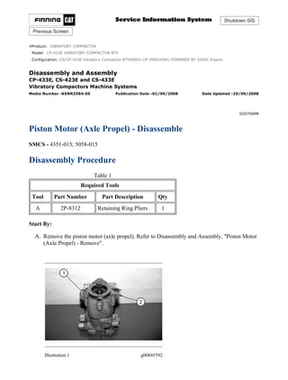
A. Remove the piston motor (axle propel). Refer to Disassembly and Assembly, "Piston Motor
(Axle Propel) - Remove".
Illustration 1 g00845592
1/9
CS/CP-433E Vibratory Compactor BTY00001-UP (MACHINE) POWERED BY 3054...
2021/4/25
https://127.0.0.1/sisweb/sisweb/techdoc/techdoc_print_page.jsp?returnurl=/sis...
2. 1. Remove bolts (1) and front cover (2) from the housing. Remove the gasket from the
housing.
Illustration 2 g00845593
2. Remove retaining ring (3) and lip type seal (4) from front cover (2) .
Illustration 3 g00845594
3. Remove retaining ring (5). Remove the bearing and shaft (6) as a unit from front cover (2) .
2/9
CS/CP-433E Vibratory Compactor BTY00001-UP (MACHINE) POWERED BY 3054...
2021/4/25
https://127.0.0.1/sisweb/sisweb/techdoc/techdoc_print_page.jsp?returnurl=/sis...
3. Illustration 4 g00845596
4. Remove retaining rings (7) from shaft (6). Use a suitable press and remove bearing (8) from
shaft (6) .
Illustration 5 g00845598
5. Put identification marks on journal bearings (10) for installation purposes. Remove journal
bearings (10) from front cover (2). Remove spring pins (9) from the front cover.
Illustration 6 g00845599
3/9
CS/CP-433E Vibratory Compactor BTY00001-UP (MACHINE) POWERED BY 3054...
2021/4/25
https://127.0.0.1/sisweb/sisweb/techdoc/techdoc_print_page.jsp?returnurl=/sis...
4. Illustration 7 g00845600
Improper assembly of parts that are spring loaded can cause bodily
injury.
To prevent possible injury, follow the established assembly procedure
and wear protective equipment.
6. Remove bolts (12) and cover (14) from the housing. Remove the gasket from the cover.
7. Remove bolts (11) and cover (17) from the housing. Remove gasket (17) from the cover.
8. Remove spring (15) and stop (16) from the servo piston.
Illustration 8 g00845601
4/9
CS/CP-433E Vibratory Compactor BTY00001-UP (MACHINE) POWERED BY 3054...
2021/4/25
https://127.0.0.1/sisweb/sisweb/techdoc/techdoc_print_page.jsp?returnurl=/sis...
5. NOTICE
Do not turn the housing upside down to remove the swashplate from
the housing.
9. Remove sleeve bearing (18) and swashplate (19) from the housing.
Illustration 9 g00845602
NOTICE
Sleeve bearing (18) must be reinstalled in the original position on
swashplate (19) .
10. Note the position of sleeve bearing (18) on swashplate (19). Remove sleeve bearing (18)
and pin (20) from swashplate (19) .
5/9
CS/CP-433E Vibratory Compactor BTY00001-UP (MACHINE) POWERED BY 3054...
2021/4/25
https://127.0.0.1/sisweb/sisweb/techdoc/techdoc_print_page.jsp?returnurl=/sis...
6. Illustration 10 g00845603
11. Use Tool (A) to remove cylinder block assembly (21) from housing (22) .
Illustration 11 g00845604
12. Remove piston assemblies (23) and slipper guide (24) from cylinder block (25) .
Illustration 12 g00845606
13. Remove retainer guide (26) from cylinder block (25) .
6/9
CS/CP-433E Vibratory Compactor BTY00001-UP (MACHINE) POWERED BY 3054...
2021/4/25
https://127.0.0.1/sisweb/sisweb/techdoc/techdoc_print_page.jsp?returnurl=/sis...
7. Illustration 13 g00845607
14. Remove pin retainer (27) and pins (28) from cylinder block (25) .
Illustration 14 g00845608
Possible injury can result when removing the retaining ring and spring.
Spring force will be released when the retaining ring is removed.
Be prepared to hold the cylinder assembly as the retaining ring is
removed.
15. Put cylinder block (25) in a press. Install a suitable piece of square steel stock against
washer (30). Put slight compression on washer (30) with the press. Remove retaining ring
(29) and slowly release the spring compression.
16. Remove washer (30), spring (31), and washer (32) from cylinder block (25) .
7/9
CS/CP-433E Vibratory Compactor BTY00001-UP (MACHINE) POWERED BY 3054...
2021/4/25
https://127.0.0.1/sisweb/sisweb/techdoc/techdoc_print_page.jsp?returnurl=/sis...
8. Illustration 15 g00845609
17. Put identification marks on valve plate (34) and locating pin (33) from installation purposes.
Remove valve plate (34) and locating pin (33) from the housing.
18. Remove needle bearing (35) from the housing.
Illustration 16 g00845610
19. Remove the servo piston (36) from housing (22) .
8/9
CS/CP-433E Vibratory Compactor BTY00001-UP (MACHINE) POWERED BY 3054...
2021/4/25
https://127.0.0.1/sisweb/sisweb/techdoc/techdoc_print_page.jsp?returnurl=/sis...
9. Illustration 17 g00845611
20. Remove piston rings (37) and the O-rings from the outer groove. Remove bearings (38)
from the inner groove.
Illustration 18 g00845613
Sudden release of spring force can cause injury.
To prevent the possibility of injury, follow the procedure to relieve the
spring pressure.
21. Remove plug (46), spring (45), and poppet (43) from the housing. Remove the shims and
the O-ring seal from plug (46) .
22. Remove plug (41) and spring (44) from both sides of the housing. Remove the O-ring seal
from each plug (41) .
23. Remove spring guide (40), valve spool (39), and spring guide (42) from the housing.
Copyright 1993 - 2021 Caterpillar Inc.
All Rights Reserved.
Private Network For SIS Licensees.
Sun Apr 25 22:39:19 UTC+0800 2021
9/9
CS/CP-433E Vibratory Compactor BTY00001-UP (MACHINE) POWERED BY 3054...
2021/4/25
https://127.0.0.1/sisweb/sisweb/techdoc/techdoc_print_page.jsp?returnurl=/sis...
10. Shutdown SIS
Previous Screen
Product: VIBRATORY COMPACTOR
Model: CP-433E VIBRATORY COMPACTOR BTY
Configuration: CS/CP-433E Vibratory Compactor BTY00001-UP (MACHINE) POWERED BY 3054C Engine
Disassembly and Assembly
CP-433E, CS-423E and CS-433E
Vibratory Compactors Machine Systems
Media Number -KENR3584-05 Publication Date -01/09/2008 Date Updated -29/09/2008
i02076912
Piston Motor (Axle Propel) - Assemble
SMCS - 4351-016; 5058-016
Assembly Procedure
Table 1
Required Tools
Tool Part Number Part Description Qty
A 2P-8312 Retaining Ring Pliers 1
1. Inspect all parts and clean all parts. If any parts are worn or damaged, use new Caterpillar
parts for replacement.
2. Inspect all seals. Damaged seals must be replaced. Use new Caterpillar seals for
replacement.
Illustration 1 g00845613
1/8
CS/CP-433E Vibratory Compactor BTY00001-UP (MACHINE) POWERED BY 3054...
2021/4/25
https://127.0.0.1/sisweb/sisweb/techdoc/techdoc_print_page.jsp?returnurl=/sis...
11. 3. Install spring guides (40) and (42) on valve spool (39). Install the valve spool in housing
(22) .
4. Install the O-ring seal on both plugs (41). Install both springs (44) and both plugs (41) in the
housing.
5. Install the O-ring seal on plug (46). Install the shims on the plug. Install poppet (43), spring
(45), and plug (46) in the housing.
Illustration 2 g00845611
Illustration 3 g00845610
6. Install bearings (38) in the inner grooves of servo piston (36). Install O-rings and piston
rings (37) in the inner groove of servo piston (36) .
7. Install servo piston (36) in the housing.
2/8
CS/CP-433E Vibratory Compactor BTY00001-UP (MACHINE) POWERED BY 3054...
2021/4/25
https://127.0.0.1/sisweb/sisweb/techdoc/techdoc_print_page.jsp?returnurl=/sis...
12. Illustration 4 g00845609
8. Install needle bearing (35) in housing (22). Install the needle bearing 2.2 ± .2 mm (0.09 ±
0.008 inch) above the inside surface of the housing.
9. Install locating pin (33) in the housing. Install the locating pin 4.52 ± .23 mm (0.170 ± 0.01
inch) above the inside surface of the housing.
10. Install valve plate (34) in the housing. The bronze side of the valve plate must be visible
inside the housing. The notch on the valve plate must engage locating pin (33) .
Illustration 5 g00845608
11. Install washer (32), spring (31), and washer (30) in cylinder block (25). Put the cylinder
block in a press. Install a suitable piece of square steel stock against washer (30). Compress
spring (31) and install retaining ring (29). Slowly release the spring compression.
3/8
CS/CP-433E Vibratory Compactor BTY00001-UP (MACHINE) POWERED BY 3054...
2021/4/25
https://127.0.0.1/sisweb/sisweb/techdoc/techdoc_print_page.jsp?returnurl=/sis...
14. 14. Install piston assemblies (23) in slipper guide (24). Install the piston assemblies and slipper
guide in the cylinder block.
Illustration 9 g00845603
15. Use Tool (A) to install cylinder block assembly (21) in housing (22) .
Illustration 10 g00845602
16. Install pin (20) in swashplate (19). Install sleeve bearing (18) on pin (20). The notched side
of the sleeve bearing must face the convex portion of the swashplate.
5/8
CS/CP-433E Vibratory Compactor BTY00001-UP (MACHINE) POWERED BY 3054...
2021/4/25
https://127.0.0.1/sisweb/sisweb/techdoc/techdoc_print_page.jsp?returnurl=/sis...
15. Illustration 11 g00845601
17. Install sleeve bearing (18) and swashplate (19) in the housing.
Illustration 12 g00845600
Illustration 13 g00845599
18. Install spring (15) and stop (16) in the servo piston.
6/8
CS/CP-433E Vibratory Compactor BTY00001-UP (MACHINE) POWERED BY 3054...
2021/4/25
https://127.0.0.1/sisweb/sisweb/techdoc/techdoc_print_page.jsp?returnurl=/sis...
16. 19. Install gasket (17), cover (13), and bolts (11). Install the gasket, cover (14), and bolts (12).
Tighten the bolts to a torque of 16 ± 3 N·m (12 ± 2 lb ft).
Illustration 14 g00845598
20. Install spring pins (9) in front cover (2) .
21. Install journal bearings (10) on the front cover and spring pins (9) .
Illustration 15 g00845596
22. Install lower retaining ring (7) on shaft (6). Use a press and install bearing (8) on shaft (6).
Install upper retaining ring (7) .
7/8
CS/CP-433E Vibratory Compactor BTY00001-UP (MACHINE) POWERED BY 3054...
2021/4/25
https://127.0.0.1/sisweb/sisweb/techdoc/techdoc_print_page.jsp?returnurl=/sis...
17. Illustration 16 g00845594
23. Install shaft (6) in front cover (2) and install retaining ring (5) .
Illustration 17 g00845970
24. Position the gasket on the housing and install front cover (2). Install seven bolts (1) .
25. Install lip type seal (4) and install retaining ring (3) .
End By: Install the piston motor (axle propel). Refer to Disassembly and Assembly, "Piston
Motor (Axle Propel) - Install".
Copyright 1993 - 2021 Caterpillar Inc.
All Rights Reserved.
Private Network For SIS Licensees.
Sun Apr 25 22:40:15 UTC+0800 2021
8/8
CS/CP-433E Vibratory Compactor BTY00001-UP (MACHINE) POWERED BY 3054...
2021/4/25
https://127.0.0.1/sisweb/sisweb/techdoc/techdoc_print_page.jsp?returnurl=/sis...
18. Shutdown SIS
Previous Screen
Product: VIBRATORY COMPACTOR
Model: CP-433E VIBRATORY COMPACTOR BTY
Configuration: CS/CP-433E Vibratory Compactor BTY00001-UP (MACHINE) POWERED BY 3054C Engine
Disassembly and Assembly
CP-433E, CS-423E and CS-433E
Vibratory Compactors Machine Systems
Media Number -KENR3584-05 Publication Date -01/09/2008 Date Updated -29/09/2008
i02076986
Piston Motor (Axle Propel) - Install
SMCS - 4351-012; 5058-012
Installation Procedure
Illustration 1 g00837607
1. Install axle propel motor (1) and bolts (3). The weight of the axle propel motor is
approximately 24 kg (52 lb).
2. Connect hose assemblies (2) on axle propel motor (1) .
Copyright 1993 - 2021 Caterpillar Inc.
All Rights Reserved.
Private Network For SIS Licensees.
Sun Apr 25 22:41:11 UTC+0800 2021
1/1
CS/CP-433E Vibratory Compactor BTY00001-UP (MACHINE) POWERED BY 3054...
2021/4/25
https://127.0.0.1/sisweb/sisweb/techdoc/techdoc_print_page.jsp?returnurl=/sis...
19. Shutdown SIS
Previous Screen
Product: VIBRATORY COMPACTOR
Model: CP-433E VIBRATORY COMPACTOR BTY
Configuration: CS/CP-433E Vibratory Compactor BTY00001-UP (MACHINE) POWERED BY 3054C Engine
Disassembly and Assembly
CP-433E, CS-423E and CS-433E
Vibratory Compactors Machine Systems
Media Number -KENR3584-05 Publication Date -01/09/2008 Date Updated -29/09/2008
i02085896
Wheel and Tire - Remove and Install
SMCS - 4202-010; 4208-010
Removal Procedure
Table 1
Required Tools
Tool Part Number Part Description Qty
A 180-3033 Stand 2
1. Engage the parking brake. Place wooden wedges in front of the drum assembly and behind
the drum assembly.
Illustration 1 g00827930
2. Raise the rear of the machine until the tires are off the floor. Install Tooling (A) under the
front of the rear frame of the machine, as shown.
1/2
CS/CP-433E Vibratory Compactor BTY00001-UP (MACHINE) POWERED BY 3054...
2021/4/25
https://127.0.0.1/sisweb/sisweb/techdoc/techdoc_print_page.jsp?returnurl=/sis...
20. 3. Remove lug nuts (2). Use two persons in order to remove the wheel and tire assembly (1).
The weight of the wheel and tire assembly is 100 kg (220 lb).
4. Repeat Step 3 in order to remove the other wheel and tire assembly.
Installation Procedure
1. Check the condition of the wheel studs. If the studs are damaged use new Caterpillar parts
for replacement.
Illustration 2 g00827930
2. Use two persons in order to install the wheel and tire assembly (2). Install lug nuts (1).
Tighten the lug nuts to a torque of 530 ± 70 N·m (390 ± 51 lb ft).
3. Repeat Step 2 in order to install the other wheel and tire assembly.
4. Raise the rear of the machine. Remove Tooling (A) and lower the machine.
Copyright 1993 - 2021 Caterpillar Inc.
All Rights Reserved.
Private Network For SIS Licensees.
Sun Apr 25 22:42:06 UTC+0800 2021
2/2
CS/CP-433E Vibratory Compactor BTY00001-UP (MACHINE) POWERED BY 3054...
2021/4/25
https://127.0.0.1/sisweb/sisweb/techdoc/techdoc_print_page.jsp?returnurl=/sis...
21. Shutdown SIS
Previous Screen
Product: VIBRATORY COMPACTOR
Model: CP-433E VIBRATORY COMPACTOR BTY
Configuration: CS/CP-433E Vibratory Compactor BTY00001-UP (MACHINE) POWERED BY 3054C Engine
Disassembly and Assembly
CP-433E, CS-423E and CS-433E
Vibratory Compactors Machine Systems
Media Number -KENR3584-05 Publication Date -01/09/2008 Date Updated -29/09/2008
i02071464
Axle - Remove
SMCS - 3260-011; 3278-011
Removal Procedure
Table 1
Required Tools
Tool Part Number Part Description Qty
A
6V-3145 Load Leveling Beam 1
138-7574 Link Brackets 2
ZZ
6V-9507 Face Seal Plug (9/16 - 18 THD) 1
6V-9828 Cap Assembly (9/16 - 18 THD) 1
6V-9509 Face Seal Plug (13/16 - 16 THD) 2
6V-9830 Cap Assembly (13/16 - 16 THD) 2
6V-9511 Face Seal Plug (1 3/16 - 12 THD) 2
6V-9832 Cap Assembly (1 3/16 - 12 THD) 2
Start By:
A. Remove the wheel and tire assemblies. Refer to Disassembly and Assembly, "Wheel and
Tire - Remove and Install".
Note: SERVICE DATA: TOOLING (ZZ) WILL NOT BE IDENTIFIED IN
PHOTOGRAPHS IN THE REMOVAL OR THE INSTALLATION. THIS TOOLING IS
SHOWN IN ORDER TO ASSIST THE EXPERIENCED SERVICEMAN.
1/3
CS/CP-433E Vibratory Compactor BTY00001-UP (MACHINE) POWERED BY 3054...
2021/4/25
https://127.0.0.1/sisweb/sisweb/techdoc/techdoc_print_page.jsp?returnurl=/sis...
22. Personal injury can result from hydraulic oil pressure and hot oil.
Hydraulic oil pressure can remain in the hydraulic system after the
engine has been stopped. Serious injury can be caused if this pressure is
not released before any service is done on the hydraulic system.
Make sure all of the work tools have been lowered to the ground, and
the oil is cool before removing any components or lines. Remove the oil
filler cap only when the engine is stopped, and the filler cap is cool
enough to touch with your bare hand.
NOTICE
Care must be taken to ensure that fluids are contained during
performance of inspection, maintenance, testing, adjusting, and repair
of the machine. Be prepared to collect the fluid with suitable containers
before opening any compartment or disassembling any component
containing fluids.
Refer to Special Publication, NENG2500, "Caterpillar Tools and Shop
Products Guide"for tools and supplies to collect and contain fluids in
Caterpillar machines.
Dispose of all fluids according to local regulations.
Note: Put identification marks on all lines, on all hoses, on all wires, and on all tubes for
installation purposes. Plug all lines, hoses, and tubes. This helps to prevent fluid loss and this
helps to keep contaminants from entering the system.
2/3
CS/CP-433E Vibratory Compactor BTY00001-UP (MACHINE) POWERED BY 3054...
2021/4/25
https://127.0.0.1/sisweb/sisweb/techdoc/techdoc_print_page.jsp?returnurl=/sis...
23. Illustration 1 g00827998
1. Disconnect hose assemblies (1) from axle propel motor (2) .
Illustration 2 g00827999
2. Attach a suitable lifting device and Tooling (A) to axle (3) .
Illustration 3 g00828002
3. Remove bolts (4) and plate (5) from each side and remove the axle from the machine. The
weight of the axle that is equipped without brakes is approximately 300 kg (650 lb). The
weight of the axle that is equipped with brakes is approximately 400 kg (875 lb).
Copyright 1993 - 2021 Caterpillar Inc.
All Rights Reserved.
Private Network For SIS Licensees.
Sun Apr 25 22:43:02 UTC+0800 2021
3/3
CS/CP-433E Vibratory Compactor BTY00001-UP (MACHINE) POWERED BY 3054...
2021/4/25
https://127.0.0.1/sisweb/sisweb/techdoc/techdoc_print_page.jsp?returnurl=/sis...
24. Shutdown SIS
Previous Screen
Product: VIBRATORY COMPACTOR
Model: CP-433E VIBRATORY COMPACTOR BTY
Configuration: CS/CP-433E Vibratory Compactor BTY00001-UP (MACHINE) POWERED BY 3054C Engine
Disassembly and Assembly
CP-433E, CS-423E and CS-433E
Vibratory Compactors Machine Systems
Media Number -KENR3584-05 Publication Date -01/09/2008 Date Updated -29/09/2008
i02070626
Axle (without Brakes) - Disassemble
SMCS - 3260-015; 3278-015
Disassembly Procedure
Table 1
Required Tools
Tool Part Number Part Description Qty
A 8H-0700 Bearing Puller 1
B 1P-1859 Retaining Ring Pliers 1
C 1P-0510 Driver Gp 1
D 154-6182 Forcing Bolt 2
E 138-7573 Link Bracket 2
Start By:
A. Remove the axle. Refer to Disassembly and Assembly, "Axle - Remove".
1. Drain the oil from the differential into a suitable container. The capacity of the differential is
approximately 9 L (2.4 US gal).
1/11
CS/CP-433E Vibratory Compactor BTY00001-UP (MACHINE) POWERED BY 3054...
2021/4/25
https://127.0.0.1/sisweb/sisweb/techdoc/techdoc_print_page.jsp?returnurl=/sis...
25. Illustration 1 g00847459
2. Drain the oil from the gearbox into a suitable container. The capacity of the gearbox is
approximately 1.2 L (0.3 US gal).
3. Remove the bolts and the propel motor from the gearbox. Install the cover and the bolts on
the gearbox.
4. Remove bolts (1) and cover (2) .
Illustration 2 g00847460
5. Remove O-ring seal (3) from cover (2) .
2/11
CS/CP-433E Vibratory Compactor BTY00001-UP (MACHINE) POWERED BY 3054...
2021/4/25
https://127.0.0.1/sisweb/sisweb/techdoc/techdoc_print_page.jsp?returnurl=/sis...
27. Illustration 6 g00847464
9. Use Tooling (A) and remove bearing (8) from gear (7) .
Illustration 7 g00847465
10. Use Tooling (A) and remove bearing (9) from gear (7) .
4/11
CS/CP-433E Vibratory Compactor BTY00001-UP (MACHINE) POWERED BY 3054...
2021/4/25
https://127.0.0.1/sisweb/sisweb/techdoc/techdoc_print_page.jsp?returnurl=/sis...
28. Illustration 8 g00847466
11. Use Tooling (A) and remove bearing (10) from gear (6) .
Illustration 9 g00847467
12. Use Tooling (B) to remove retaining ring (11). Use Tooling (A) and remove bearing (12)
from gear (6) .
Illustration 10 g00847468
13. Remove bolts (13) and remove cover (14) .
5/11
CS/CP-433E Vibratory Compactor BTY00001-UP (MACHINE) POWERED BY 3054...
2021/4/25
https://127.0.0.1/sisweb/sisweb/techdoc/techdoc_print_page.jsp?returnurl=/sis...
29. Please write to us.
Our email:
aservicemanualpdf@yahoo.com
Please go to the homepage
to get the full manual, or
other brand PDF manuals.
Home Site:
aservicemanualpdf.com
30. Thank you very much for
your reading. Please Click
Here. Then Get COMPLETE
MANUAL. NO WAITING
NOTE:
If there is no response to
click on the link above,
please download the PDF
document first and then
click on it.
GET MORE OTHER MANUALS https://www.aservicemanualpdf.com/
GET MORE OTHER MANUALS https://www.aservicemanualpdf.com/
31. Illustration 11 g00847469
14. Drain the oil from the wheel hub into a suitable container. The capacity of the wheel hub is
approximately 1.3 L (0.3 US gal).
15. Remove screws (15) and end cover (16) .
Illustration 12 g00847471
16. Remove bolts (17), washers (18), gears (19), and the 84 needle bearings.
6/11
CS/CP-433E Vibratory Compactor BTY00001-UP (MACHINE) POWERED BY 3054...
2021/4/25
https://127.0.0.1/sisweb/sisweb/techdoc/techdoc_print_page.jsp?returnurl=/sis...
32. Illustration 13 g01064656
17. Remove O-ring seal (20) from ring gear (23) .
18. Remove shaft (21) .
19. Remove bolts (22) .
Illustration 14 g01064989
20. Install bolts (22) to ring gear (23), as shown. Turn the bolts evenly in order to remove the
sun gear.
Illustration 15 g01064990
21. Use a suitable press and remove bushings (24) from ring gear (23) .
7/11
CS/CP-433E Vibratory Compactor BTY00001-UP (MACHINE) POWERED BY 3054...
2021/4/25
https://127.0.0.1/sisweb/sisweb/techdoc/techdoc_print_page.jsp?returnurl=/sis...
33. Illustration 16 g01061619
Illustration 17 g01061625
22. Remove bearing cone (26), hub (25), and bearing cone (27) .
Illustration 18 g01061629
23. Remove lip seal (28) and bearing cups (29) from hub (25) .
24. Repeat Steps 14 through 23 in order to disassemble the other wheel hub.
8/11
CS/CP-433E Vibratory Compactor BTY00001-UP (MACHINE) POWERED BY 3054...
2021/4/25
https://127.0.0.1/sisweb/sisweb/techdoc/techdoc_print_page.jsp?returnurl=/sis...