
Recommended
More Related Content
Similar to Caterpillar Cat 980G Wheel Loader (Prefix 9CM) Service Repair Manual Instant Download.pdf
Similar to Caterpillar Cat 980G Wheel Loader (Prefix 9CM) Service Repair Manual Instant Download.pdf (20)
More from ze3xiandiao
More from ze3xiandiao (20)
Recently uploaded
Recently uploaded (20)
Caterpillar Cat 980G Wheel Loader (Prefix 9CM) Service Repair Manual Instant Download.pdf
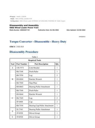
- 1. Product: WHEEL LOADER Model: 980G WHEEL LOADER 9CM Configuration: 980G Wheel Loader 9CM00001-UP (MACHINE) POWERED BY 3406C Engine Disassembly and Assembly 980G Wheel Loader Power Train Media Number -SENR5877-07 Publication Date -01/09/2004 Date Updated -23/09/2004 i04400923 Torque Converter - Disassemble - Heavy Duty SMCS - 3101-015 Disassembly Procedure Table 1 Required Tools Tool Part Number Part Description Qty A 138-7573 Link Bracket 1 B 8B-7548 Push-Puller 1 8B-7550 Leg 2 8H-0684 Ratchet Wrench 1 8B-7560 Step Plate 1 8H-0663 Bearing Puller Attachment 1 C 8B-7548 Push-Puller 1 8H-0684 Ratchet Wrench 1 8B-7549 Leg 2 5P-4808 Cap 2 8B-7554 Bearing Cup Puller Attachment 1 D 5F-7343 Bearing Puller Attachment 1 1P-0520 Driver Group 1 E 1P-0520 Driver Group 1 1/17 980G Wheel Loader 9CM00001-UP (MACHINE) POWERED BY 3406C Engine(SE... 2021/12/18 https://127.0.0.1/sisweb/sisweb/techdoc/techdoc_print_page.jsp?returnurl=/sis...
- 2. Start By: a. Separate the torque converter from the transmission and from the output transfer gears. Refer to Disassembly and Assembly, "Torque Converter from Transmission, Output Transfer Gears - Separate" for the machine that is being serviced. 1. Place the torque converter housing assembly on wood blocks. Illustration 1 g00503225 2. Remove eight bolts (1) and the washers from torque converter housing assembly (2). Illustration 2 g00503286 3. Install Tooling (A) to torque converter housing assembly (2), as shown. Attach a hoist and suitable lifting chains to Tooling (A). 4. Use three 3/8" - 16 NC forcing screws (3) to loosen housing assembly (2) from the torque converter. 5. Use the hoist to remove housing assembly (2) from the torque converter. The weight of housing assembly (2) is 120 kg (265 lb). 2/17 980G Wheel Loader 9CM00001-UP (MACHINE) POWERED BY 3406C Engine(SE... 2021/12/18 https://127.0.0.1/sisweb/sisweb/techdoc/techdoc_print_page.jsp?returnurl=/sis...
- 3. Illustration 3 g00503287 6. Remove O-ring seal (4) from torque converter housing assembly (2). Illustration 4 g00503288 7. Remove thirteen bolts (5) and the washers from pump adapter (6) and torque converter housing assembly (2). Illustration 5 g00503289 8. Use three 3/8" - 16 NC forcing screws (7) to remove pump adapter (6) from torque converter housing assembly (2). 3/17 980G Wheel Loader 9CM00001-UP (MACHINE) POWERED BY 3406C Engine(SE... 2021/12/18 https://127.0.0.1/sisweb/sisweb/techdoc/techdoc_print_page.jsp?returnurl=/sis...
- 4. Illustration 6 g00503291 9. Remove bearing cup (8), O-ring seal (10) and shims (9) from pump adapter (6). Illustration 7 g00503292 10. Remove pump drive gear (11) from torque converter housing assembly (2). Illustration 8 g00503294 11. Use Tooling (B) to remove bearing cones (12) from each side to pump drive gear (11). 4/17 980G Wheel Loader 9CM00001-UP (MACHINE) POWERED BY 3406C Engine(SE... 2021/12/18 https://127.0.0.1/sisweb/sisweb/techdoc/techdoc_print_page.jsp?returnurl=/sis...
- 5. Illustration 9 g00503296 12. Use Tooling (C) to remove bearing cup (13) from torque converter housing assembly (2). Illustration 10 g00503297 13. Remove bolt (14) and the washer from torque converter housing assembly (2). 14. Use 3/8" - 16 NC forcing screw (16) to push the shaft assembly out of torque converter housing assembly (2). 15. Remove idler gear (15) from torque converter housing assembly (2). Illustration 11 g00503298 5/17 980G Wheel Loader 9CM00001-UP (MACHINE) POWERED BY 3406C Engine(SE... 2021/12/18 https://127.0.0.1/sisweb/sisweb/techdoc/techdoc_print_page.jsp?returnurl=/sis...
- 6. 16. Remove O-ring seal (17) from shaft assembly (18). Illustration 12 g00503299 17. Remove bearing cone (19), bearing cone spacer (20) and bearing cone (21) from idler gear (15). Illustration 13 g00503301 18. Use Tooling (C) to remove bearing cup (22) from idler gear (15). 6/17 980G Wheel Loader 9CM00001-UP (MACHINE) POWERED BY 3406C Engine(SE... 2021/12/18 https://127.0.0.1/sisweb/sisweb/techdoc/techdoc_print_page.jsp?returnurl=/sis...
- 7. Illustration 14 g00503302 19. Remove bearing cup spacer (23) from idler gear (15). Illustration 15 g00503308 20. Remove retaining ring (24) from idler gear (15). Illustration 16 g00503309 7/17 980G Wheel Loader 9CM00001-UP (MACHINE) POWERED BY 3406C Engine(SE... 2021/12/18 https://127.0.0.1/sisweb/sisweb/techdoc/techdoc_print_page.jsp?returnurl=/sis...
- 8. 21. Use Tooling (C) to remove bearing cup (25) from idler gear (15). Illustration 17 g00503312 22. Remove two studs (26) from torque converter housing assembly (2). Illustration 18 g00503314 23. Remove retaining ring (27) and bearing carrier (28) from the carrier assembly. Illustration 19 g00503315 24. Remove O-ring seal (29) from bearing carrier (28). 8/17 980G Wheel Loader 9CM00001-UP (MACHINE) POWERED BY 3406C Engine(SE... 2021/12/18 https://127.0.0.1/sisweb/sisweb/techdoc/techdoc_print_page.jsp?returnurl=/sis...
- 9. 25. Remove seal ring (30) from ring carrier (31). Illustration 20 g00503316 26. Use Tooling (D) and a press to remove ring carrier (31) from bearing carrier (28). Illustration 21 g00503318 27. Remove retaining ring (32) from bearing carrier (28). Illustration 22 g00503319 28. Use Tooling (D) and a press to remove inner bearing (33) from bearing carrier (28). 9/17 980G Wheel Loader 9CM00001-UP (MACHINE) POWERED BY 3406C Engine(SE... 2021/12/18 https://127.0.0.1/sisweb/sisweb/techdoc/techdoc_print_page.jsp?returnurl=/sis...
- 10. Illustration 23 g00503321 29. Remove twelve bolts (34) and the washers from drive gear (35). 30. Remove drive gear (35) from the drive flange. Illustration 24 g00503322 31. Use Tooling (E) and a press to remove the outer bearing race from drive gear (35). Illustration 25 g00503344 32. Remove retaining ring (36) from drive gear (35). 10/17 980G Wheel Loader 9CM00001-UP (MACHINE) POWERED BY 3406C Engine(S... 2021/12/18 https://127.0.0.1/sisweb/sisweb/techdoc/techdoc_print_page.jsp?returnurl=/sis...
- 11. Illustration 26 g00503345 33. Remove 36 bolts (37) from drive flange (38) and rotating housing (39). Illustration 27 g00503347 34. Use two bolts (37) as forcing screws to remove drive flange (38) from rotating housing (39). The weight of drive flange (38) is 23 kg (51 lb). Illustration 28 g00503348 35. Place the impeller hub on wood blocks. 36. Remove twelve bolts (40) from drive flange (38). 11/17 980G Wheel Loader 9CM00001-UP (MACHINE) POWERED BY 3406C Engine(S... 2021/12/18 https://127.0.0.1/sisweb/sisweb/techdoc/techdoc_print_page.jsp?returnurl=/sis...
- 12. Illustration 29 g00503350 37. Remove drive flange (38) from the impeller hub and converter impeller (41). Illustration 30 g00503351 38. Remove converter impeller (41) from impeller hub (42). Illustration 31 g00503352 39. Remove two thrust bearing races (43) and the thrust bearing from the carrier assembly. 12/17 980G Wheel Loader 9CM00001-UP (MACHINE) POWERED BY 3406C Engine(S... 2021/12/18 https://127.0.0.1/sisweb/sisweb/techdoc/techdoc_print_page.jsp?returnurl=/sis...
- 13. Illustration 32 g00503533 40. Remove carrier assembly (44) and the stator as a unit from rotating housing (39). Illustration 33 g00503534 41. Remove snap ring (45). Illustration 34 g00503535 42. Heat stator (46) and carrier assembly (44) as a unit to a minimum temperature of 121°C (250°F) for one hour. This will expand stator (46). 43. Remove stator (46) from carrier assembly (44). 13/17 980G Wheel Loader 9CM00001-UP (MACHINE) POWERED BY 3406C Engine(S... 2021/12/18 https://127.0.0.1/sisweb/sisweb/techdoc/techdoc_print_page.jsp?returnurl=/sis...
- 14. Illustration 35 g00503536 44. Remove retainer ring (47) from stator (46). Illustration 36 g00503537 45. Remove sleeve bearing (48) from carrier assembly (44). Illustration 37 g00503538 46. Remove two thrust bearing races (49) and the thrust bearing from the hub. 14/17 980G Wheel Loader 9CM00001-UP (MACHINE) POWERED BY 3406C Engine(S... 2021/12/18 https://127.0.0.1/sisweb/sisweb/techdoc/techdoc_print_page.jsp?returnurl=/sis...
- 15. Illustration 38 g00503539 47. Remove converter turbine (50) and turbine hub (51) as a unit from rotating housing (39). Illustration 39 g00503540 48. Remove twenty bolts (52) and the washers from converter turbine (50). 49. Remove converter turbine (50) from turbine hub (51). Illustration 40 g00503541 50. Remove retaining ring (53) from turbine hub (51). 15/17 980G Wheel Loader 9CM00001-UP (MACHINE) POWERED BY 3406C Engine(S... 2021/12/18 https://127.0.0.1/sisweb/sisweb/techdoc/techdoc_print_page.jsp?returnurl=/sis...
- 16. Illustration 41 g00503542 51. Remove two thrust bearing races (54) and thrust bearing (55) from the cover assembly. Illustration 42 g00503564 52. Remove eight bolts (56) and the washers from cover assembly (57). 53. Remove cover assembly (57) from rotating housing (39). 54. Remove ring seal (58) from rotating housing (39). Illustration 43 g00503567 55. Remove sleeve bearing (59) from cover assembly (57). 16/17 980G Wheel Loader 9CM00001-UP (MACHINE) POWERED BY 3406C Engine(S... 2021/12/18 https://127.0.0.1/sisweb/sisweb/techdoc/techdoc_print_page.jsp?returnurl=/sis...
- 17. Product: WHEEL LOADER Model: 980G WHEEL LOADER 9CM Configuration: 980G Wheel Loader 9CM00001-UP (MACHINE) POWERED BY 3406C Engine Disassembly and Assembly 980G Wheel Loader Power Train Media Number -SENR5877-07 Publication Date -01/09/2004 Date Updated -23/09/2004 i04400940 Torque Converter - Assemble - Heavy duty SMCS - 3101-016 Assembly Procedure Table 1 Required Tools Tool Part Number Part Description Qty A 138-7573 Link Bracket 3 B 8T-5096 Dial Indicator Test Group 1 5P-2390 Gauge Tool Group 1 C 1P-0520 Driver Group 1 Note: Cleanliness is an important factor. Before assembly, all parts should be thoroughly cleaned in cleaning fluid. Allow the parts to air dry. Wiping cloths or rags should not be used to dry parts. Lint may be deposited on the parts which may cause later trouble. Inspect all parts. If any parts are worn or damaged, use new parts for replacement. Note: Apply oil to all of the bearings before assembly. 1/18 980G Wheel Loader 9CM00001-UP (MACHINE) POWERED BY 3406C Engine(SE... 2021/12/18 https://127.0.0.1/sisweb/sisweb/techdoc/techdoc_print_page.jsp?returnurl=/sis...
- 18. Illustration 1 g00504278 1. Use Tooling (C) to install sleeve bearing (59) in cover assembly (57). Sleeve bearing (59) must be even with the outside surface of cover assembly (57). Illustration 2 g00504279 2. Install cover assembly (57) to rotating housing (39). Illustration 3 g00503564 3. Install ring seal (58) to rotating housing (39). 2/18 980G Wheel Loader 9CM00001-UP (MACHINE) POWERED BY 3406C Engine(SE... 2021/12/18 https://127.0.0.1/sisweb/sisweb/techdoc/techdoc_print_page.jsp?returnurl=/sis...
- 19. 4. Install eight bolts (56) and the washers. Tighten the bolts to a torque of 30 ± 5 N·m (22 ± 4 lb ft). Illustration 4 g00504307 5. Install thrust bearing race (54), thrust bearing (55), and thrust bearing race (54) to cover assembly (57). Illustration 5 g00504312 6. Install retaining ring (53) in turbine hub (51). Illustration 6 g00504313 3/18 980G Wheel Loader 9CM00001-UP (MACHINE) POWERED BY 3406C Engine(SE... 2021/12/18 https://127.0.0.1/sisweb/sisweb/techdoc/techdoc_print_page.jsp?returnurl=/sis...
- 20. 7. Install converter turbine (50) on turbine hub (51). Illustration 7 g00504315 8. Install twenty bolts (52). Tighten the bolts to a torque of 50 ± 7 N·m (37 ± 5 lb ft). Illustration 8 g00504382 9. Install turbine hub (51) and converter turbine (50) as a unit to rotating housing (39). Illustration 9 g00503538 10. Install two thrust bearing races (49) and the bearing to the hub. 4/18 980G Wheel Loader 9CM00001-UP (MACHINE) POWERED BY 3406C Engine(SE... 2021/12/18 https://127.0.0.1/sisweb/sisweb/techdoc/techdoc_print_page.jsp?returnurl=/sis...
- 21. Illustration 10 g00504436 11. Use Tooling (C) to install sleeve bearing (48) to carrier assembly (44). Bearing sleeve (48) must be even with the counterbore of carrier assembly (44). Illustration 11 g00504882 12. Install retainer ring (47) in stator (46). Illustration 12 g00504931 13. Position carrier assembly (44) on a wood block. 5/18 980G Wheel Loader 9CM00001-UP (MACHINE) POWERED BY 3406C Engine(SE... 2021/12/18 https://127.0.0.1/sisweb/sisweb/techdoc/techdoc_print_page.jsp?returnurl=/sis...
- 22. 14. Use proper equipment to handle stator (46). Heat stator (46) to a maximum temperature of 121°C (250°F) for one hour. 15. Install stator (46) on carrier assembly (44). Illustration 13 g00504935 16. Install snap ring (45) in stator (46). Illustration 14 g00505049 17. Install stator (46) and carrier assembly (44) in rotating housing (39). Illustration 15 g00503352 6/18 980G Wheel Loader 9CM00001-UP (MACHINE) POWERED BY 3406C Engine(SE... 2021/12/18 https://127.0.0.1/sisweb/sisweb/techdoc/techdoc_print_page.jsp?returnurl=/sis...
- 23. 18. Install two thrust bearing races (43) and the thrust bearing to the carrier assembly. Illustration 16 g00503351 19. Position impeller hub (42) on a wood block. 20. Install converter impeller (41) on impeller hub (42). Illustration 17 g00503350 21. Install drive flange (38) on converter impeller (41). Illustration 18 g00503348 7/18 980G Wheel Loader 9CM00001-UP (MACHINE) POWERED BY 3406C Engine(SE... 2021/12/18 https://127.0.0.1/sisweb/sisweb/techdoc/techdoc_print_page.jsp?returnurl=/sis...
- 24. 22. Install twelve bolts (40). Tighten the bolts to a torque of 80 ± 10 N·m (60 ± 7 lb ft). Illustration 19 g00503345 23. Install drive flange (38) on rotating housing (39). The weight of drive flange (38) is 23 kg (51 lb). 24. Install 36 bolts (37) and the washers. Tighten the bolts to a torque of 30 ± 5 N·m (22 ± 4 lb ft). Illustration 20 g00505183 25. Install retaining ring (36) in the groove of drive gear (35). 8/18 980G Wheel Loader 9CM00001-UP (MACHINE) POWERED BY 3406C Engine(SE... 2021/12/18 https://127.0.0.1/sisweb/sisweb/techdoc/techdoc_print_page.jsp?returnurl=/sis...
- 25. Illustration 21 g00505224 26. Use the proper equipment to handle outer bearing race (60). Lower the temperature of outer bearing race (60). 27. Install outer bearing race (60) in drive gear (35). Make sure that outer bearing race (60) makes contact with retaining ring (36). Illustration 22 g00505319 28. Install drive gear (35) on drive flange (38). Illustration 23 g00505349 29. Install twelve bolts (34) and the washers. Tighten the bolts to a torque of 50 ± 7 N·m (37 ± 5 lb ft). 9/18 980G Wheel Loader 9CM00001-UP (MACHINE) POWERED BY 3406C Engine(SE... 2021/12/18 https://127.0.0.1/sisweb/sisweb/techdoc/techdoc_print_page.jsp?returnurl=/sis...
- 26. Illustration 24 g00505352 30. Use the proper equipment to handle inner bearing (33). Heat inner bearing (33) to a maximum temperature of 135°C (275°F). Install inner bearing (33) on bearing carrier (28). Illustration 25 g00505358 31. Install retaining ring (32) in the groove of bearing carrier (28). Illustration 26 g00505359 32. Use the proper equipment to handle ring carrier (31). Heat ring carrier (31) to a maximum temperature of 135°C (275°F). Install ring carrier (31) on bearing carrier (28). 10/18 980G Wheel Loader 9CM00001-UP (MACHINE) POWERED BY 3406C Engine(S... 2021/12/18 https://127.0.0.1/sisweb/sisweb/techdoc/techdoc_print_page.jsp?returnurl=/sis...
- 27. Illustration 27 g00505387 33. Install seal ring (30) on ring carrier (31). 34. Install O-ring seal (29) on bearing carrier (28). Illustration 28 g00505395 35. Install bearing carrier (28) in drive flange (38). Illustration 29 g00505423 36. Install retaining ring (27) in carrier assembly (44) in order to hold bearing carrier (28) in place. 11/18 980G Wheel Loader 9CM00001-UP (MACHINE) POWERED BY 3406C Engine(S... 2021/12/18 https://127.0.0.1/sisweb/sisweb/techdoc/techdoc_print_page.jsp?returnurl=/sis...
- 28. Suggest: If the above button click is invalid. Please download this document first, and then click the above link to download the complete manual. Thank you so much for reading
- 29. Illustration 30 g00503312 37. Install two studs (26) in torque converter housing assembly (2). Tighten the studs to a torque of 100 ± 15 N·m (74 ± 11 lb ft). Illustration 31 g00505444 38. Install retaining ring (24) in the groove of idler gear (15). Illustration 32 g00505465 39. Use the proper equipment to handle bearing cup (25). Lower the temperature of bearing cup (25). Install bearing cup (25) in idler gear (15). 12/18 980G Wheel Loader 9CM00001-UP (MACHINE) POWERED BY 3406C Engine(S... 2021/12/18 https://127.0.0.1/sisweb/sisweb/techdoc/techdoc_print_page.jsp?returnurl=/sis...