Caterpillar Cat 637E Wheel Scraper (Prefix 1LB) Service Repair Manual (1LB00001 and up).pdf
1. Shutdown SIS
Previous Screen
Product: WHEEL SCRAPER
Model: 637E WHEEL SCRAPER 1LB
Configuration: 637E Wheel Scraper 1LB00001-UP (MACHINE) POWERED BY 3306 Engine
Disassembly and Assembly
631E & 637E TRACTOR POWER TRAIN
Media Number -SENR4143-01 Publication Date -01/10/2004 Date Updated -17/03/2010
SENR41430012
Transmission Hydraulic Control Valves
SMCS - 3152-015; 3152-011; 3152-012; 3167-016
Remove Transmission Hydraulic Control Valves
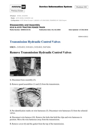
1. Disconnect hose assembly (3).
2. Remove guard assemblies (1) and (2) from the transmission.
3. Put identification marks on wire harnesses (5). Disconnect wire harnesses (5) from the solenoid
valves.
4. Disconnect wire harness (10). Remove the bolts that hold the clips and wire harnesses in
position. Move the wire harnesses away from the transmission.
5. Remove cover (6) and the gasket from the top of the transmission.
1/24(W)
w
2021/8/22
https://127.0.0.1/sisweb/sisweb/techdoc/techdoc_print_page.jsp?returnurl=/sisweb/sisw...
2. 6. Remove cover (8) from the switch manifold.
7. Remove three plugs (9) and pressure tap (7) from the switch manifold.
8. Remove two tube assemblies (4) from the transmission.
9. Remove four sleeves (12) from the switch manifold. Remove the O-ring seal from the sleeves.
10. Disconnect wire harness (13) from switch assembly (11).
11. Remove switch assembly (11) from the switch manifold.
12. Remove adapters (15) and sleeves (14). Remove the O-ring seals from the sleeves.
13. Remove elbow (17) and sleeve (16). Remove the O-ring seals from the sleeve.
2/24(W)
w
2021/8/22
https://127.0.0.1/sisweb/sisweb/techdoc/techdoc_print_page.jsp?returnurl=/sisweb/sisw...
3. 14. Remove five 3/8"-16 NC bolts (18) and three bolts (19). Fasten a hoist to the transmission
control group. Move the transmission control group toward the front of the machine, and remove
it from the transmission. The weight of the transmission control group is 69 kg (152 lb.).
15. Remove switch manifold (20) from the side of the transmission. Remove the O-ring seals from
the switch manifold.
16. Remove sleeves (21) and (22). Remove the O-ring seals from the sleeves.
Install Transmission Hydraulic Control Valves
1. Install the O-ring seals on sleeves (1) and (2). Put clean oil on the O-ring seals. Install sleeves
(1) and (2) in the transmission.
3/24(W)
w
2021/8/22
https://127.0.0.1/sisweb/sisweb/techdoc/techdoc_print_page.jsp?returnurl=/sisweb/sisw...
4. 2. Install the six O-ring seals in switch manifold (3). Put clean oil on the O-ring seals.
3. Put switch manifold (3) in position, and install the four bolts that hold it in place. Tighten the
bolts to a torque of 48 ± 4 N·m (35 ± 3 lb.ft.).
4. Fasten a hoist to the transmission control group. Put the transmission control group in position
on the two sleeves, and lower it into place in the transmission.
5. Install three bolts (4) and five bolts (5). Tighten the bolts to a torque of 48 ± 4 N·m (35 ± 3
lb.ft.).
6. Install the O-ring seals on sleeve (6). Make sure the O-ring seal is in position on elbow (7). Put
clean oil on the O-ring seals.
4/24(W)
w
2021/8/22
https://127.0.0.1/sisweb/sisweb/techdoc/techdoc_print_page.jsp?returnurl=/sisweb/sisw...
5. 7. Put sleeve (6) and elbow (7) in position, and install two bolts (8). Tighten the bolts to a torque
of 30 ± 4 N·m (22 ± 3 lb.ft.).
8. Install the O-ring seals on sleeves (9). Put clean oil on the O-ring seals.
9. Install sleeves (9) and adapters (10).
10. Align the groove in coupling (12) with the pin in the selector spool, and install coupling (12)
and switch assembly (14).
11. Connect wire harness (13) to switch assembly (14).
12. Install the O-ring seals on sleeves (11). Put clean oil on the O-ring seals.
13. Install sleeves (11) in the switch manifold.
14. Install three plugs (20) and pressure tap (18).
15. Install the gasket and cover (19) on the switch manifold.
16. Install the gasket and cover (16) on the top of the transmission.
17. Connect wire harnesses (15) to the solenoid valves.
5/24(W)
w
2021/8/22
https://127.0.0.1/sisweb/sisweb/techdoc/techdoc_print_page.jsp?returnurl=/sisweb/sisw...
6. 18. Connect wire harness (21). Put the wire harnesses in position, and install the clips and bolts
that hold them in place.
19. Make sure the O-ring seals are in position in the ends of tube assemblies (17), and install the
tube assemblies.
20. Install guard assemblies (22) and (23).
21. Connect hose assembly (24).
22. Adjust the transmission hydraulic control valves. See Testing And Adjusting.
Disassemble Transmission Hydraulic Control Valves
START BY:
a. remove transmission hydraulic control valves
1. Remove O-ring seals (1) from the switch manifold.
2. If necessary, remove bearing (2).
3. Remove tube assemblies (4) and solenoid valves (3) from the switch manifold. Remove the O-
ring seals from the switch manifold.
6/24(W)
w
2021/8/22
https://127.0.0.1/sisweb/sisweb/techdoc/techdoc_print_page.jsp?returnurl=/sisweb/sisw...
7. 4. Remove the bolts, cover (6) and wire harness (7) from the switch manifold.
5. Remove seal (5).
6. Remove the bolts, cover (8) and valve group (9).
7. Remove valve groups (10) and (11) from the manifold.
8. Remove the bolts and plate (12) from manifold (13).
7/24(W)
w
2021/8/22
https://127.0.0.1/sisweb/sisweb/techdoc/techdoc_print_page.jsp?returnurl=/sisweb/sisw...
8. 9. Remove plugs (14) from valve group (9).
NOTE: The pressure control valve for each clutch is identified on the pressure control valve body
by a letter at location (15). The letter is also stamped on body (26).
NOTICE
Do not at any time mix the components between valve groups during
disassembly or assembly.
NOTE: Valve group (A) is for clutch No. 2. Valve group (B) is for clutch No. 1. Valve group (C)
is for clutch No. 7. Valve group (D) is for the torque converter lockup clutch. Valve group (E) is
for clutch No. 5. Valve group (F) is for clutch No. 4. Valve group (G) is for clutch No. 6. Valve
group (H) is for clutch No. 3.
10. Use the following procedures to disassemble the valve groups.
a. Remove two screws (28) and body (26) from the valve body.
NOTE: On valve groups (A) and (G), there is a pin inside springs (20).
b. Remove two springs (20), shims (21) and two pistons (22) from body (26).
NOTE: On valve groups (D) and (G), there is no center plug of plugs (27).
c. Remove spring (23), orifice (24), O-ring seal (25) and plugs (27) from body (26).
d. Remove stop (19), spool (18) and spring (16) from the valve body.
e. Remove slug (17) from spool (18).
8/24(W)
w
2021/8/22
https://127.0.0.1/sisweb/sisweb/techdoc/techdoc_print_page.jsp?returnurl=/sisweb/sisw...
9. 11. Use the following procedures to disassemble spools (18) from the valve groups.
a. Use tool (A) to remove snap ring (32) from the spool.
b. Remove retainer (31), spring (30) and ball (29) from the spool.
12. Remove bolts (34), plate (33), spring (37), shims (36) and spool assembly (35) from valve
group (10).
13. Use tool (A), and remove snap ring (38) from spool assembly (35).
14. Remove retainer (40), spring (39) and plunger (41) from the spool assembly.
9/24(W)
w
2021/8/22
https://127.0.0.1/sisweb/sisweb/techdoc/techdoc_print_page.jsp?returnurl=/sisweb/sisw...
10. There is spring pressure behind cover (45). To prevent personal injury,
hold cover (45) when the bolts are removed.
15. Remove cover (45), spool assembly (44) and spring (49) from the valve body.
16. Remove shims (48) from spool assembly (44).
17. Remove spiral ring (42), retainer (46), spring (43) and check valve (47) from the spool
assembly.
18. Remove cover (50), spool (51) and spring (54) from the valve body.
19. Remove O-ring seal (53), pin (52) and the valve from cover (50).
10/24(W)
w
2021/8/22
https://127.0.0.1/sisweb/sisweb/techdoc/techdoc_print_page.jsp?returnurl=/sisweb/sisw...
11. 20. Use tool (A), and remove snap ring (59) from spool (51).
21. Remove seat (58), ball (56) and spring (55).
22. Remove O-ring seal (57) from the seat.
23. Remove two bolts (61) and actuator (60).
24. Remove two bolts (63) and cover (62).
11/24(W)
w
2021/8/22
https://127.0.0.1/sisweb/sisweb/techdoc/techdoc_print_page.jsp?returnurl=/sisweb/sisw...
12. 25. If necessary, remove bearing (64) from cover (62).
26. Remove rotor (65) from the actuator.
27. Remove two bolts (66) and vane (67).
28. Remove plugs (68) and (69) from the actuator. Remove the valve that is under each plug.
29. If necessary, remove bearing (70) from the actuator.
12/24(W)
w
2021/8/22
https://127.0.0.1/sisweb/sisweb/techdoc/techdoc_print_page.jsp?returnurl=/sisweb/sisw...
13. 30. Remove two bolts (71). Remove retainers (74) and springs (72).
31. Remove bolt (73), the washer and rotary selector spool (75).
32. Remove pin (78) and cam (76) from rotary selector spool.
33. Remove pin (69). Remove the screen from the rotary selector spool.
Support (80) holds a spring under compression. To prevent personal
injury, hold support (80) when bolts (81) are removed.
34. Remove bolts (81) and support (80).
35. Remove two dowels (79) from the support if a replacement is necessary.
13/24(W)
w
2021/8/22
https://127.0.0.1/sisweb/sisweb/techdoc/techdoc_print_page.jsp?returnurl=/sisweb/sisw...
14. 36. Remove spool (82) and spring (84) from the valve body.
37. Remove shims (83) from the spool.
38. Use tool (A), and remove snap ring (88) from spool (82). Remove slug (87), spring (86) and
ball (85) from the spool.
39. Remove cap (93), spring (91) and valve (90) from body (89). Remove spacer (92) from the
valve.
40. Remove body (89) from the valve body. Remove the O-ring seal from body (89).
Assemble Transmission Hydraulic Control Valves
14/24(W)
w
2021/8/22
https://127.0.0.1/sisweb/sisweb/techdoc/techdoc_print_page.jsp?returnurl=/sisweb/sisw...
15. 1. Install O-ring seal (2) on body (3). Install body (3) in selector control valve (1). Tighten body
(3) to a torque of 41 ± 7 N·m (30 ± 5 lb.ft.).
2. Put clean transmission oil on the outside diameter of valve (7). Install spacer (6) in valve (7).
3. Install valve (7), spring (5) and cap (4) on the selector control valve. Tighten cap (4) to a torque
of 41 ± 7 N·m (30 ± 5 lb.ft.).
4. Put clean SAE 30 oil on slug (9). Install ball (11), spring (10) and slug (9) in spool (12). Use
tool (A) to install snap ring (8).
15/24(W)
w
2021/8/22
https://127.0.0.1/sisweb/sisweb/techdoc/techdoc_print_page.jsp?returnurl=/sisweb/sisw...
16. 5. Put clean SAE 30 oil on spool (12). Install shims (15) in the end of spool (12).
6. Install spring (14) and spool (12) in selector valve (13) as shown.
7. Install two dowels (16) on the top and bottom of support (17). Install the dowels so they extend
6.50 ± 0.25 mm (.256 ± .010 in.) above the surface.
8. Put support (17) in position on selector valve (13). Install the two bolts that hold it in position.
9. Install the screen in rotary selector spool (19). Tighten the screen to a torque of 6.1 ± 0.7 N·m
(54 ± 6 lb.in.). Install cam (18) in the rotary selector spool, and install pin (22) that holds the cam
in place. Install the pin until it is 1.0 ± 0.5 mm (.04 ± .02 in.) below the surface of the rotary
selector spool.
16/24(W)
w
2021/8/22
https://127.0.0.1/sisweb/sisweb/techdoc/techdoc_print_page.jsp?returnurl=/sisweb/sisw...
17. 10. Install pin (21). Install the pin with the head of the pin up as shown when two holes (20) are in
the position shown.
11. Put clean SAE 30 oil on rotary selector spool (19). Install the rotary selector spool in the valve
body.
12. Install bolt (28) and washer (25) that hold the rotary selector spool in position.
13. Install two springs (24) and (30), two retainers (25) and (27) and bolts (23) that hold the
springs in position on the support. Make sure the side of each spring is 4.5 ± 0.5 mm (.18 ± .02 in.)
from the side of the selector valve.
14. Loosen bolts (29) enough to make sure the rollers in springs (24) and (20) are in the center of
the notches in the cam. Tighten bolts (29).
15. If bearing (31) was removed, use tooling (B) to install bearing (31) in actuator body (32).
Install the bearing so that it extends 3.00 ± 0.50 mm (.118 ± .020 in.) above the surface.
17/24(W)
w
2021/8/22
https://127.0.0.1/sisweb/sisweb/techdoc/techdoc_print_page.jsp?returnurl=/sisweb/sisw...
18. 16. Put O-ring seal (34) in position on plug (33). Put clean SAE 30 oil on the O-ring seal and on
valve (35).
17. Install valves (35) in the actuator body. Make sure the flat end of the valve is installed first.
Install plug (33).
18. Install vane (36) and two bolts (37) in the actuator body. Do not tighten bolts (37) at this time.
Make sure notch (38) on the vane is in the position shown.
19. Put clean SAE 10 oil on all surfaces of the rotor. Install rotor (39) in the actuator.
20. If bearing (40) was removed, use tooling (B) to install bearing (40) in cover (41). Install the
bearing so it is 1.30 ± 0.25 mm (.051 ± .010 in.) below surface (42).
18/24(W)
w
2021/8/22
https://127.0.0.1/sisweb/sisweb/techdoc/techdoc_print_page.jsp?returnurl=/sisweb/sisw...
19. 21. Install cover (41) on the actuator body. Install two bolts (43) that hold the cover in position.
Tighten bolts (43) to a torque of 30 ± 4 N·m (22 ± 3 lb.ft.).
22. Tighten bolts (37) (see Step 18) to a torque of 15 ± 3 N·m (11 ± 2 lb.ft.).
23. The rotor must turn freely through 300° of rotation.
24. Install the actuator on the selector valve body. Make sure the larger groove (slot) (44) in rotor
(39) is in alignment with the head on the pin on rotor selector spool (19).
25. Install the two bolts that hold the actuator in position on the selector valve. Tighten the bolts to
a torque of 30 ± 4 N·m (22 ± 3 lb.ft.).
26. Install O-ring seal (47) on seat (46). Put clean SAE 30 oil on the O-ring seal.
19/24(W)
w
2021/8/22
https://127.0.0.1/sisweb/sisweb/techdoc/techdoc_print_page.jsp?returnurl=/sisweb/sisw...
20. 27. Install spring (49), ball (48) and seat (46). Use tool (A) to install snap ring (45).
28. Put the shims, spring (51) and neutralizer valve spool (50) in position in the selector valve
body.
29. Put the O-ring seal and pin in position in cover (52). Put clean SAE 30 oil on the O-ring seal.
Put the cover in position on the selector valve body, and install the bolts that hold it.
30. Install valve (57), spring (56), retainer (55) and spiral ring (54) in priority reducing valve spool
(58).
31. Put shims (59) in position in the end of spool (58). Put clean SAE 30 oil on the outside
diameter of spool (58).
32. Install spring (60), spool (58) and cover (53) on the selector control valve.
20/24(W)
w
2021/8/22
https://127.0.0.1/sisweb/sisweb/techdoc/techdoc_print_page.jsp?returnurl=/sisweb/sisw...
21. 33. Put plunger (62), spring (65) and retainer (61) in position in spool assembly (63), and install
snap ring (64) with tool (A).
34. Install shims (66) in spool assembly (63).
35. Put spool assembly (63), spring (67) and plate (68) in position in the valve body, and install
the two bolts that hold them in place.
36. Put ball (70), spring (71) and retainer (72) in position in valve (69), and install snap ring (73)
with tool (A).
21/24(W)
w
2021/8/22
https://127.0.0.1/sisweb/sisweb/techdoc/techdoc_print_page.jsp?returnurl=/sisweb/sisw...
22. NOTE: The pressure control valve for each clutch is identified on the pressure control valve body
by a letter. There is a corresponding letter on each of bodies (86).
NOTICE
Do not at any time mix the components between valve groups during
disassembly or assembly.
NOTE: Valve Group A is for clutch No. 2. Valve group B is for clutch No. 1. Valve group C is
for clutch No. 7. Valve group D is for the torque converter lockup clutch. Valve group E is for
clutch No. 5. Valve group F is for clutch No. 4. Valve group G is for clutch No. 6. Valve group H
is for clutch No. 3.
37. Use the following procedure to assemble the valve groups.
a. Put clean SAE 30 oil on all the surfaces of spool (75) and slug (79). Install slug (79) in the
spool as shown.
b. Install spring (74), spool (75) and stop (80) in the pressure control valve.
NOTE: There is no plug (88) in valve group (D) or (G).
c. Make sure the O-ring seals are in position on plugs (87), (88) and (89). Install the plugs in the
body.
22/24(W)
w
2021/8/22
https://127.0.0.1/sisweb/sisweb/techdoc/techdoc_print_page.jsp?returnurl=/sisweb/sisw...
23. d. Put clean SAE 30 oil on the O-ring seal (85). Install O-ring seal (85), orifice (84) and spring
(83) in body (86).
e. Put clean SAE 30 oil on all the surfaces of pistons (82) and (78). Install piston (82) in piston
(78) as shown.
NOTE: On valve groups (A) and (G), a pin goes inside inner spring (76).
f. Install shims (77) and springs (81), and (76) in the end of piston (82).
g. Install piston (78) in body (86). Install body (86) on the pressure control valve. Install the two
screws that hold the body in position.
38. Make sure the O-ring seals are in position on plugs (90). Put clean oil on the O-ring seals.
39. Install plugs (90).
40. Put plate (92) in position on manifold (93), and install two bolts (91). Tighten the bolts to a
torque of 30 ± 4 N·m (22 ± 3 lb.ft.).
41. Put selector valve (13) and pressure control valve (94) in position, and install the bolts that
hold them in place. Tighten the bolts to a torque of 30 ± 4 N·m (22 ± 3 lb.ft.).
23/24(W)
w
2021/8/22
https://127.0.0.1/sisweb/sisweb/techdoc/techdoc_print_page.jsp?returnurl=/sisweb/sisw...
24. 42. Put pressure control valve (95) and cover (96) in position, and install the bolts that hold them
in place. Tighten the bolts to a torque of 30 ± 4 N·m (22 ± 3 lb.ft.).
43. Use tooling (B), and install seal (97) in the switch manifold as shown.
44. Put wire harness (99) and cover (98) in position in the switch manifold, and install the bolts
that hold them in place.
45. Put O-ring seals (103) in position in solenoid valves (102). Install the solenoid valves and tube
assemblies (104).
46. Use tooling (B), and install bearing (100) in the switch manifold until it extends a maximum of
0.5 mm (.02 in.) above the counterbore in the switch manifold.
47. Install O-ring seals (101) in the switch manifold.
END BY:
a. install transmission hydraulic control valves
Copyright 1993 - 2021 Caterpillar Inc.
All Rights Reserved.
Private Network For SIS Licensees.
Sun Aug 22 00:29:45 UTC+0800 2021
24/24(W)
w
2021/8/22
https://127.0.0.1/sisweb/sisweb/techdoc/techdoc_print_page.jsp?returnurl=/sisweb/sisw...
25. Shutdown SIS
Previous Screen
Product: WHEEL SCRAPER
Model: 637E WHEEL SCRAPER 1LB
Configuration: 637E Wheel Scraper 1LB00001-UP (MACHINE) POWERED BY 3306 Engine
Disassembly and Assembly
631E & 637E TRACTOR POWER TRAIN
Media Number -SENR4143-01 Publication Date -01/10/2004 Date Updated -17/03/2010
SENR41430013
Transmission Oil Filter
SMCS - 3164-010
Remove And Install Transmission Oil Filter
1. Drain the oil from the transmission oil filter.
2. Disconnect hose assembly (2).
3. Remove four bolts (3), and remove transmission oil filter (1) from the transfer gear case.
4. Remove the O-ring seals from the transfer gear case.
NOTE: The following steps are for installation of the transmission oil filter.
5. Put the O-ring seals in position in the transfer gear case. Put clean oil on the O-ring seals.
6. Put transmission oil filter (1) in position, and install bolts (3).
7. Connect hose assembly (2).
8. Check the oil level in the transmission. See the Maintenance Guide.
Copyright 1993 - 2021 Caterpillar Inc.
All Rights Reserved.
Private Network For SIS Licensees.
Sun Aug 22 00:30:41 UTC+0800 2021
1/1(W)
w
2021/8/22
https://127.0.0.1/sisweb/sisweb/techdoc/techdoc_print_page.jsp?returnurl=/sisweb/sisw...
26. Shutdown SIS
Previous Screen
Product: WHEEL SCRAPER
Model: 637E WHEEL SCRAPER 1LB
Configuration: 637E Wheel Scraper 1LB00001-UP (MACHINE) POWERED BY 3306 Engine
Disassembly and Assembly
631E & 637E TRACTOR POWER TRAIN
Media Number -SENR4143-01 Publication Date -01/10/2004 Date Updated -17/03/2010
SENR41430014
Transmission Scavenge Pump
SMCS - 3115-016; 3115-010; 3115-015
Remove And Install Transmission Scavenge Pump
1. Drain the oil from the transmission.
2. Remove two bolts (2) and scavenge pump (1).
3. Remove the O-ring seals from the scavenge pump.
NOTE: The following steps are for installation of the transmission scavenge pump.
4. Put the three O-ring seals in position on scavenge pump (1). Put clean oil on the O-ring seals.
5. Put scavenge pump (1) in position, and install two bolts (2).
6. Fill the transmission with oil to the correct level. See the Maintenance Guide.
Disassemble Transmission Scavenge Pump
1/4(W)
w
2021/8/22
https://127.0.0.1/sisweb/sisweb/techdoc/techdoc_print_page.jsp?returnurl=/sisweb/sisw...
27. START BY:
a. remove transmission scavenge pump
1. Remove six bolts (1) and cover (2). Remove the O-ring seal from the cover.
2. Remove two bearings (3) from the cover.
3. Remove two gears (4) and body (5).
4. Remove two dowels (6) from each side of the body if a replacement is necessary.
2/4(W)
w
2021/8/22
https://127.0.0.1/sisweb/sisweb/techdoc/techdoc_print_page.jsp?returnurl=/sisweb/sisw...
28. 5. Remove the O-ring seal from the manifold. Use tooling (A) to remove bearings (7) from
manifold (8).
Assemble Transmission Scavenge Pump
1. Use tooling (A) to install bearings (1) in manifold (3). Make sure the bearing joint in each
bearing is 30° ± 15° from a centerline as shown. Install each bearing so it is 1.57 mm (.062 in.)
below the surface.
2. Install O-ring seal (2) on the manifold. Put clean oil on the O-ring seal and on the bore of each
bearing.
3. Install four dowels (4) in body (5). Install the dowels so that dimension (X) is 6.4 mm (.25 in.).
3/4(W)
w
2021/8/22
https://127.0.0.1/sisweb/sisweb/techdoc/techdoc_print_page.jsp?returnurl=/sisweb/sisw...
29. Please write to us.
Our email:
aservicemanualpdf@yahoo.com
Please go to the homepage
to get the full manual, or
other brand PDF manuals.
Home Site:
aservicemanualpdf.com
30. Thank you very much for
your reading. Please Click
Here. Then Get COMPLETE
MANUAL. NO WAITING
NOTE:
If there is no response to
click on the link above,
please download the PDF
document first and then
click on it.
GET MORE OTHER MANUALS https://www.aservicemanualpdf.com/
GET MORE OTHER MANUALS https://www.aservicemanualpdf.com/
31. 4. Install body (5) on the manifold. Make sure the bolt holes in the body and the manifold are in
alignment.
5. Install gear (7) and drive gear (6) as shown. Make sure the drive gear (6) is in the bore of
manifold (3) that has the step on the bottom surface of the manifold.
6. Use tooling (A) to install bearings (8) in cover (9). Make sure the bearing joint in each bearing
is 30° ± 15° from the centerline as shown. Install the bearings so that they are 1.57 mm (.062 in.)
below the surface. Put clean oil on the bore of each bearing.
7. Install O-ring seal (10) on cover (9). Install cover (9) on body (5). Make sure the bolt holes in
cover (9) are in alignment with the bolt holes in body (5).
8. Install the six bolts that hold the pump components together.
9. Make sure the pump will turn freely by hand.
END BY:
a. install transmission scavenge pump
Copyright 1993 - 2021 Caterpillar Inc.
All Rights Reserved.
Private Network For SIS Licensees.
Sun Aug 22 00:31:37 UTC+0800 2021
4/4(W)
w
2021/8/22
https://127.0.0.1/sisweb/sisweb/techdoc/techdoc_print_page.jsp?returnurl=/sisweb/sisw...
32. Shutdown SIS
Previous Screen
Product: WHEEL SCRAPER
Model: 637E WHEEL SCRAPER 1LB
Configuration: 637E Wheel Scraper 1LB00001-UP (MACHINE) POWERED BY 3306 Engine
Disassembly and Assembly
631E & 637E TRACTOR POWER TRAIN
Media Number -SENR4143-01 Publication Date -01/10/2004 Date Updated -17/03/2010
SENR41430015
Transmission Oil Pump
SMCS - 3153-011; 3153-012; 3153-015; 3153-016
Remove Transmission Oil Pump
START BY:
a. remove transmission scavenge pump
1. Remove the guard assembly from the rear of the transmission. The weight of the guard
assembly is 177 kg (390 lb.).
2. Remove four bolts and screen (1) from the manifold.
1/8(W)
w
2021/8/22
https://127.0.0.1/sisweb/sisweb/techdoc/techdoc_print_page.jsp?returnurl=/sisweb/sisw...
33. 3. Remove four bolts, cover (2) and magnetic screen (3).
4. Fasten tool (A) and a hoist to the manifold as shown. Remove the bolts that hold the manifold
in position.
5. Use two 3/8"-16 NC forcing screws (4) to move the manifold away from the transmission
transfer gears. Remove manifold (5). The weight of the manifold and transmission oil pump is
approximately 25 kg (55 lb.).
6. Remove coupling (6).
7. Remove spiral ring (7) from the coupling if a replacement is necessary.
2/8(W)
w
2021/8/22
https://127.0.0.1/sisweb/sisweb/techdoc/techdoc_print_page.jsp?returnurl=/sisweb/sisw...