
Recommended
Recommended
More Related Content
More from ze3xiandiao
More from ze3xiandiao (20)
Recently uploaded
Recently uploaded (20)
Caterpillar Cat 980F WHEEL LOADER (Prefix 3HK) Service Repair Manual Instant Download.pdf
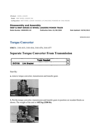
- 1. Product: WHEEL LOADER Model: 980F WHEEL LOADER 3HK Configuration: 980F WHEEL LOADER 3HK00001-UP (MACHINE) POWERED BY 3406 ENGINE Disassembly and Assembly 980F & 980F SERIES II WHEEL LOADERS POWER TRAIN Media Number -SENR4991-02 Publication Date -01/08/2004 Date Updated -18/04/2012 SENR49910025 Torque Converter SMCS - 3101-015; 3101-016; 3101-076; 3101-077 Separate Torque Converter From Transmission Start By: a. remove torque converter, transmission and transfer gears 1. Put the torque converter, transmission and transfer gears in position on wooden blocks as shown. The weight of the unit is 1452 kg (3200 lb). 1/26(W) w 2022/2/22 https://127.0.0.1/sisweb/sisweb/techdoc/techdoc_print_page.jsp?returnurl=/sisweb/sisw...
- 2. 2. Remove three bolts (2) and manifold (1) from the transmission case and the elbow on the torque converter. Remove the O-ring seals from the elbow. 3. Remove tool (A) and a hoist to torque converter (3) as shown. 4. Remove bolts (4) and the washers that hold the torque converter to the transmission. Remove torque converter (3) from the transmission. The weight of the torque converter is 211 kg (465 lb). 5. Remove the O-ring seal from the transmission case. Connect Torque Converter To Transmission 1. Check the condition of the O-ring seal used between the transmission and torque converter and the O-ring seals used on the torque converter elbow. If the seals are worn or damaged, use new parts for replacement. 2. Install O-ring seal (2) on the transmission case. Put a thin coat of clean oil on the O-ring seal. 3. Fasten tool (A) and a hoist to torque converter (1) as shown. 4. Align the dowels in the transmission case with the dowel holes in the torque converter housing. Put torque converter (1) in position on the transmission. 5. Install the bolts and washers that hold the torque converter to the transmission. 2/26(W) w 2022/2/22 https://127.0.0.1/sisweb/sisweb/techdoc/techdoc_print_page.jsp?returnurl=/sisweb/sisw...
- 3. 6. Be sure O-ring seals (3) are in position on the elbow for the torque converter and on manifold (4). Put clean oil on the O-ring seals. 7. Install manifold (4) on the transmission case and the torque converter elbow. End By: a. install torque converter, transmission and transfer gears Disassemble Torque Converter *part of 8B7548 Push-Puller Start By: a. separate torque converter from transmission 3/26(W) w 2022/2/22 https://127.0.0.1/sisweb/sisweb/techdoc/techdoc_print_page.jsp?returnurl=/sisweb/sisw...
- 4. 1. Remove bolts (1) and the washers that hold the torque converter to the cover assembly. 2. Fasten tool (A) and a hoist on cover assembly (3) as shown. 3. Use three 3/8" - 16 NC forcing screws (2) to loosen cover assembly (3) from the torque converter. Use tool (A) and a hoist to remove cover assembly (3). The weight of the cover assembly is 120 kg (265 lb). 4. Remove O-ring seal (4) from the cover assembly. 5. Remove the bolts, adapter (6) and elbow (5) from the cover assembly. 6. Remove the O-ring seals from the adapter and the elbow. 4/26(W) w 2022/2/22 https://127.0.0.1/sisweb/sisweb/techdoc/techdoc_print_page.jsp?returnurl=/sisweb/sisw...
- 5. 7. Remove bolts (7) and the washers that hold pump adapter (8) to the cover assembly. 8. Use three 3/8" - 16 NC forcing screws (9) to remove pump adapter (8) from the cover assembly. 9. Remove bearing cup (10), O-ring seal (12) and shims (11) from pump adapter (8). 10. Remove pump gear (13) from the cover assembly. 11. Use tooling (B), and remove bearing cones (14) from each side of pump gear (13). 5/26(W) w 2022/2/22 https://127.0.0.1/sisweb/sisweb/techdoc/techdoc_print_page.jsp?returnurl=/sisweb/sisw...
- 6. 12. Use tooling (C) to remove bearing cup (15) from the cover assembly. 13. Remove bolt (16) and the washer from the cover assembly. 14. Use a 3/8" - 16 NC forcing screw (18) to push the shaft assembly out of the cover assembly. Remove transfer gear (17) from the cover assembly. 15. Remove O-ring seal (19) from shaft assembly (20). 16. Remove bearing cone (21), spacer (22) and bearing cone (23) from transfer gear (17). 6/26(W) w 2022/2/22 https://127.0.0.1/sisweb/sisweb/techdoc/techdoc_print_page.jsp?returnurl=/sisweb/sisw...
- 7. 17. Use tooling (C) to remove bearing cup (24) from transfer gear (17). 18. Remove spacer (25) from transfer gear (17). 19. Remove retaining ring (26) from transfer gear (17). 20. Use tooling (C), and remove bearing cup (27) from transfer gear (17). 21. If necessary, remove studs (28) from the cover assembly. 7/26(W) w 2022/2/22 https://127.0.0.1/sisweb/sisweb/techdoc/techdoc_print_page.jsp?returnurl=/sisweb/sisw...
- 8. 22. Remove retaining rings (29) and bearing carrier (30) from the carrier assembly. 23. Remove O-ring seal (31) from bearing carrier (30) and seal ring (32) from ring carrier (33). 24. Use tooling (D) and a press to remove ring carrier (33) from bearing carrier (30). 25. Remove retaining ring (34) from bearing carrier (30). 26. Use tooling (D) and a press to remove inner bearing (35) from bearing carrier (30). 27. Remove bolts (36) and the washers and drive gear (37) from the drive flange. 8/26(W) w 2022/2/22 https://127.0.0.1/sisweb/sisweb/techdoc/techdoc_print_page.jsp?returnurl=/sisweb/sisw...
- 9. 28. Use tool (E) and a press to remove the outer bearing race from drive gear (37). 29. Remove bolts (39) that hold drive flange (38) to rotating housing (40). 30. Use two 5/16" - 18 NC forcing screws (41) to remove drive flange (38) from rotating housing (40). The weight of the drive flange is 23 kg (51 lb). 31. Remove bolts (43) and washers (42) that hold the hub and impeller to the drive flange. 32. Use tool (E), and remove the hub from drive flange (38). 9/26(W) w 2022/2/22 https://127.0.0.1/sisweb/sisweb/techdoc/techdoc_print_page.jsp?returnurl=/sisweb/sisw...
- 10. 33. Remove impeller (44) from drive flange (38). If necessary, remove dowels (45) from the drive flange. 34. Remove two thrust bearing races (46) and the thrust bearing from the carrier assembly. 35. Remove carrier assembly (47) and the stator as a unit from rotating housing (40). 36. Remove retaining ring (48) that holds stator (49) to carrier assembly (47). 10/26(W) w 2022/2/22 https://127.0.0.1/sisweb/sisweb/techdoc/techdoc_print_page.jsp?returnurl=/sisweb/sisw...
- 11. 37. Heat stator (49) and carrier assembly (47) as a unit to a minimum temperature of 121°C (250°F) for one hour to expand the stator. Remove stator (49) from carrier assembly (47). 38. Remove retaining ring (50) from stator (48). 39. Remove sleeve bearing (51) from carrier assembly (47). 40. Remove thrust race (52) and the thrust bearing from the hub. 41. Remove turbine (53) and hub (54) as a unit from the rotating housing. 11/26(W) w 2022/2/22 https://127.0.0.1/sisweb/sisweb/techdoc/techdoc_print_page.jsp?returnurl=/sisweb/sisw...
- 12. 42. Remove bolts (55) and the washers. Remove turbine (53) from the hub (54). 43. Remove retaining ring (56) from the hub. 44. Remove two thrust bearing races (57) and thrust bearing (58) from the cover assembly. 45. Remove bolts (59) and the washers. Remove cover (60) from rotating housing (40). 46. Remove sleeve bearing (61) from the cover. Assemble Torque Converter 12/26(W) w 2022/2/22 https://127.0.0.1/sisweb/sisweb/techdoc/techdoc_print_page.jsp?returnurl=/sisweb/sisw...
- 13. 1. Check all parts of the torque converter for wear or damage. If any of the parts are worm or damaged, use new parts for replacement. Be sure all parts of the torque converter are thoroughly clean and free of dirt and debris prior to assembly. 2. Using tool (A), install the sleeve bearing in cover (1). Install the sleeve bearing until it is even with the outside surface of the cover. 3. Put cover (1) in position on rotating housing (2). Install the bolts and washers that hold cover (1) in place. Tighten the bolts to a torque of 30 ± 5 N·m (22 ± 4 lb ft). 4. Put thrust bearing race (5), thrust bearing (4), and thrust bearing race (3) in position on the cover. 13/26(W) w 2022/2/22 https://127.0.0.1/sisweb/sisweb/techdoc/techdoc_print_page.jsp?returnurl=/sisweb/sisw...
- 14. 5. Install retaining ring (6) in hub (7). 6. Put turbine (8) in position on hub (7) as shown. Install the bolts that hold the turbine in place. Tighten the bolts to a torque of 55 ± 10 N·m (40 ± 7 lb ft). 7. Put turbine (8) and the hub as a unit in position in the housing. Check the clearance between the hub and sleeve bearing in the cover. The clearance must be 0.150 ± 0.051 mm (.0059 ± .0020 in). 14/26(W) w 2022/2/22 https://127.0.0.1/sisweb/sisweb/techdoc/techdoc_print_page.jsp?returnurl=/sisweb/sisw...
- 15. 8. Check the clearance between the turbine and the rotating housing. The distance must be 2.39 ± 0.51 mm (.094 ± .020 in) (new) with a maximum permissible distance (worn) of 3.58 mm (.141 in). See dimension (C). 9. Put thrust bearing race (11), thrust bearing (10) and thrust bearing race (9) in position on hub (7) as shown. 10. Using tool (A), install sleeve bearing (12) in carrier assembly (13). Be sure the bearing is installed even with the counterbore of the carrier assembly. 11. Install retaining ring (14) in stator (15). 12. Heat stator (15) to a maximum temperature of 121°C (250°F) for one hour. Install stator (15) on carrier assembly (13) as shown. 15/26(W) w 2022/2/22 https://127.0.0.1/sisweb/sisweb/techdoc/techdoc_print_page.jsp?returnurl=/sisweb/sisw...
- 16. 13. Install retaining ring (16) in stator (15). 14. Put carrier assembly (13) and the stator in position in the rotating housing. Check the clearance between the hub and the bearing in the carrier assembly. The clearance must be 0.150 ± 0.051 mm (.0059 ± .0020 in). 15. Check the clearance between the stator and the turbine. The distance must be 0.76 ± 0.25 mm (.030 ± .010 in) (new) with a maximum permissible distance (worn) of 1.14 mm (.045 in). See Dimension (D). 16/26(W) w 2022/2/22 https://127.0.0.1/sisweb/sisweb/techdoc/techdoc_print_page.jsp?returnurl=/sisweb/sisw...
- 17. 16. Put thrust bearing race (19), thrust bearing (18) and thrust bearing race (17) in position on the carrier assembly. 17. Install dowels (22) in drive flange (21) until they are 19.0 mm (.75 in) above the outside of the dowel bore. 18. Align dowels (22) with the dowel holes in converter impeller (20). Put converter impeller (20) in position in drive flange (21). 19. Align dowels (22) with the dowel holes in impeller hub (23). Put impeller hub (23) in position in converter impeller (20). 20. Carefully put the drive flange, the impeller and the hub as a unit on their opposite side as shown. Install washers (25) and bolts (24) that hold the drive flange, impeller and hub together. Tighten the bolts to a torque 80 ± 10 N·m (60 ± 7 lb ft). 17/26(W) w 2022/2/22 https://127.0.0.1/sisweb/sisweb/techdoc/techdoc_print_page.jsp?returnurl=/sisweb/sisw...
- 18. 21. Check the clearance between the impeller and the stator. The distance must be 0.81 ± 0.25 mm (.032 ± .010 in) (new) with a maximum permissible distance (worn) of 1.22 mm (.048 in). See dimension (F). 22. Check the clearance between the impeller and the rotating housing. The distance must be 1.55 ± 0.33 mm (.061 ± .013 in) (new) with a maximum permissible distance (worn) of 2.34 mm (.092 in). See dimension (E). 23. Put drive flange (21) in position on rotating housing (2). Install the bolts and washers that hold it. Tighten the bolts to a torque of 30 ± 5 N·m (22 ± 4 lb ft). 24. Install retaining ring (27) in the groove of drive gear (26). 18/26(W) w 2022/2/22 https://127.0.0.1/sisweb/sisweb/techdoc/techdoc_print_page.jsp?returnurl=/sisweb/sisw...
- 19. 25. Lower the temperature of outer bearing race (28). Install outer bearing race (28) in drive gear (26) until it makes contact with retaining ring (27). 26. Put drive gear (26) in position on the drive flange. Install the bolts and washers that hold it. Tighten the bolts to a torque of 50 ± 7 N·m (37 ± 5 lb ft). 27. Heat inner bearing (29) to a maximum temperature of 135°C (275°F). Install inner bearing (29) on bearing carrier (30). 28. Install retaining ring (31) in the groove of bearing carrier (30). 19/26(W) w 2022/2/22 https://127.0.0.1/sisweb/sisweb/techdoc/techdoc_print_page.jsp?returnurl=/sisweb/sisw...
- 20. 29. Heat ring carrier (32) to a maximum temperature of 135°C (275°F). Install ring carrier (32) on bearing carrier (30). 30. Install O-ring seal (33) on bearing carrier (30). 31. Install seal ring (34) on ring carrier (32). 32. Check the clearance between the impeller hub and bearing carrier (30). The distance must be 0.150 ± 0.051 mm (.0059 ± .0020 in). See dimension (G). 33. Install bearing carrier (30) in the drive flange. 20/26(W) w 2022/2/22 https://127.0.0.1/sisweb/sisweb/techdoc/techdoc_print_page.jsp?returnurl=/sisweb/sisw...
- 21. 34. Install retaining ring (35) in the groove of the carrier assembly to hold bearing carrier (30) in place. 35. Install retaining ring (36) in the groove of drive gear (26). 36. Install studs (37) in the cover assembly. Tighten the studs to a torque of 100 ± 15 N·m (74 ± 11 lb ft). 37. Install retaining ring (38) in the groove of transfer gear (39). 21/26(W) w 2022/2/22 https://127.0.0.1/sisweb/sisweb/techdoc/techdoc_print_page.jsp?returnurl=/sisweb/sisw...
- 22. 38. Lower the temperature of bearing cup (40). Install bearing cup (40) in transfer gear (39). 39. Put transfer gear (39) on its opposite side. Install spacer (41) in gear (39) as shown. Be sure the notch in spacer (41) is against the retaining ring. 40. Lower the temperature of bearing cup (42). Install bearing cup (42) in transfer gear (39). 41. Install spacer (45) and bearing cones (43) in transfer gear (39). 42. Put clean hydraulic oil on O-ring seal (46). Install O-ring seal (46) on shaft assembly (47). 22/26(W) w 2022/2/22 https://127.0.0.1/sisweb/sisweb/techdoc/techdoc_print_page.jsp?returnurl=/sisweb/sisw...
- 23. 43. Install a 1/2" - 13 NC guide pin (48) in shaft assembly (47). 44. Put transfer gear (39) in position in the cover assembly, and install shaft assembly (47). Remove guide pin (48) from the shaft assembly. 45. Install the bolt and washer that holds shaft assembly (47) in place in the cover assembly. Tighten the bolt to a torque of 110 ± 5 N·m (81 ± 4 lb ft). 46. Heat bearing cones (49) to a maximum temperature of 135°C (275°F). Install a bearing cone (49) on each side of pump gear (50) as shown. 47. Lower the temperature of bearing cup (51). Install bearing cup (51) in the cover assembly as shown. 48. Install pump gear (50) in the cover assembly. 23/26(W) w 2022/2/22 https://127.0.0.1/sisweb/sisweb/techdoc/techdoc_print_page.jsp?returnurl=/sisweb/sisw...
- 24. 49. Lower the temperature of bearing cup (52). Install bearing cup (52) in pump adapter (53). NOTE: If the thickness of shims (55) must be determined, see the topic "Procedure For Pump Drive End Play Adjustment" in the 980F Wheel Loader Power Train Specifications, Form No. SENR4988. 50. Put original shims (55) in position on pump adapter (53). 51. Put clean hydraulic oil on O-ring seal (54). Install O-ring seal (54) on pump adapter (53). 52. Install two 5/8" - 16 NC guide pins (56) in the cover assembly. 53. Install pump adapter (53) on the cover assembly. Install the bolts and washers that hold pump adapter (53) in place. Tighten the bolts to a torque of 110 ± 5 N·m (80 ± 4 lb ft). 54. Use tooling (B) as shown to check bearing end play. The bearing end play must be 0.15 ± 0.05 mm (.006 ± .002 in). Add or remove shims to get the correct bearing end play. 24/26(W) w 2022/2/22 https://127.0.0.1/sisweb/sisweb/techdoc/techdoc_print_page.jsp?returnurl=/sisweb/sisw...
- 25. 55. Be sure O-ring seals (57) are in position on elbow (58). Install elbow (58) on the cover assembly. 56. Be sure the O-ring seal is in position on adapter (59). Install adapter (59) in the cover assembly. 57. Put clean hydraulic oil on O-ring seal (60). Install O-ring seal (60) on the cover assembly. 58. Install two 1/2" - 13 NC guide pins (61) in the carrier assembly. 59. Fasten tool (C) and a hoist on cover assembly (62). Put cover assembly (62) in position on the torque converter. 25/26(W) w 2022/2/22 https://127.0.0.1/sisweb/sisweb/techdoc/techdoc_print_page.jsp?returnurl=/sisweb/sisw...
- 26. 60. Install bolts (63) and the washers that hold the cover assembly to the torque converter. Tighten the bolts to a torque of 110 ± 5 N·m (80 ± 4 lb ft). End By: a. connect torque converter to transmission 26/26(W) w 2022/2/22 https://127.0.0.1/sisweb/sisweb/techdoc/techdoc_print_page.jsp?returnurl=/sisweb/sisw...
- 27. Product: WHEEL LOADER Model: 980F WHEEL LOADER 3HK Configuration: 980F WHEEL LOADER 3HK00001-UP (MACHINE) POWERED BY 3406 ENGINE Disassembly and Assembly 980F & 980F SERIES II WHEEL LOADERS POWER TRAIN Media Number -SENR4991-02 Publication Date -01/08/2004 Date Updated -18/04/2012 SENR49910026 Transmission Hydraulic Control Valves SMCS - 3152; 3158; 3181-015; 3181-016; 3181-011; 3181-012 Remove Transmission Hydraulic Control Valves Start By: a. remove seat assembly NOTE: In the following procedure, the transmission has been removed from the machine. The transmission hydraulic control valves can be removed with the transmission in the machine. 1. Remove bolts (1), cover assembly (2) and the gasket from the transmission case. 1/13(W) w 2022/2/22 https://127.0.0.1/sisweb/sisweb/techdoc/techdoc_print_page.jsp?returnurl=/sisweb/sisw...
- 28. 2. Remove bolt (4) and washer (3) that hold sleeves (5) in the selector and pressure control valve group. 3. Remove sleeves (5) from the transmission case and the selector and pressure control valve group. 4. Remove the O-ring seals from sleeves (5). 5. Remove adapter (6) and the spring from the transmission case. Remove the O-ring seal from adapter (6). 6. Install a 3/8" - 16 NC forged eyebolt (9) in sleeve (7) as shown. Remove sleeve (7) from the selector and pressure control valve group. 7. Remove O-ring seals (8) from sleeve (7). 8. Remove four bolts (10) that hold the transmission hydraulic control valves to the planetary group. Remove two bolts (11) for the installation of tool (A). 2/13(W) w 2022/2/22 https://127.0.0.1/sisweb/sisweb/techdoc/techdoc_print_page.jsp?returnurl=/sisweb/sisw...
- 29. Suggest: If the above button click is invalid. Please download this document first, and then click the above link to download the complete manual. Thank you so much for reading
- 30. 9. Fasten tool (A) to the transmission hydraulic control valves with two bolts (11). Fasten a hoist to tool (A) as shown. Remove transmission hydraulic control valves (12) from the planetary group. The weight of the transmission hydraulic control valves is 36 kg (80 lb). Install Transmission Hydraulic Control Valves 1. Check the condition of all O-ring seals for wear or damage. If any of the seals are worn or damaged, use new parts for replacement. 2. Fasten tool (A) to transmission hydraulic control valves (1) with two mounting bolts (2). Fasten a hoist to tool (A). Put transmission hydraulic control valves (1) in position on the planetary group. 3. Remove tool (A) from the transmission hydraulic control valves, and reinstall bolts (2). Tighten the bolts to a torque of 30 ± 4 N·m (22 ± 3 lb ft). 4. Install four bolts (3) that hold the transmission hydraulic control valves to the planetary group. Tighten the bolts to a torque of 48 ± 4 N·m (35 ± 3 lb ft). 5. Install O-ring seals (5) on sleeve (4). 3/13(W) w 2022/2/22 https://127.0.0.1/sisweb/sisweb/techdoc/techdoc_print_page.jsp?returnurl=/sisweb/sisw...