The document provides instructions for removing and installing a transmission oil filter and transmission electronic control module on a 627G wheel scraper. It also details procedures for disassembling the transmission hydraulic control valve, including removing springs, spools, pistons, and other components. Safety notices are included to contain fluids and release spring pressures safely.
Fleet management these days is next to impossible without connected vehicle solutions. Why? Well, fleet trackers and accompanying connected vehicle management solutions tend to offer quite a few hard-to-ignore benefits to fleet managers and businesses alike. Let’s check them out!
Comprehensive program for Agricultural Finance, the Automotive Sector, and Empowerment . We will define the full scope and provide a detailed two-week plan for identifying strategic partners in each area within Limpopo, including target areas.:
1. Agricultural : Supporting Primary and Secondary Agriculture
• Scope: Provide support solutions to enhance agricultural productivity and sustainability.
• Target Areas: Polokwane, Tzaneen, Thohoyandou, Makhado, and Giyani.
2. Automotive Sector: Partnerships with Mechanics and Panel Beater Shops
• Scope: Develop collaborations with automotive service providers to improve service quality and business operations.
• Target Areas: Polokwane, Lephalale, Mokopane, Phalaborwa, and Bela-Bela.
3. Empowerment : Focusing on Women Empowerment
• Scope: Provide business support support and training to women-owned businesses, promoting economic inclusion.
• Target Areas: Polokwane, Thohoyandou, Musina, Burgersfort, and Louis Trichardt.
We will also prioritize Industrial Economic Zone areas and their priorities.
Sign up on https://profilesmes.online/welcome/
To be eligible:
1. You must have a registered business and operate in Limpopo
2. Generate revenue
3. Sectors : Agriculture ( primary and secondary) and Automative
Women and Youth are encouraged to apply even if you don't fall in those sectors.
Why Is Your BMW X3 Hood Not Responding To Release CommandsDart Auto
Experiencing difficulty opening your BMW X3's hood? This guide explores potential issues like mechanical obstruction, hood release mechanism failure, electrical problems, and emergency release malfunctions. Troubleshooting tips include basic checks, clearing obstructions, applying pressure, and using the emergency release.
𝘼𝙣𝙩𝙞𝙦𝙪𝙚 𝙋𝙡𝙖𝙨𝙩𝙞𝙘 𝙏𝙧𝙖𝙙𝙚𝙧𝙨 𝙞𝙨 𝙫𝙚𝙧𝙮 𝙛𝙖𝙢𝙤𝙪𝙨 𝙛𝙤𝙧 𝙢𝙖𝙣𝙪𝙛𝙖𝙘𝙩𝙪𝙧𝙞𝙣𝙜 𝙩𝙝𝙚𝙞𝙧 𝙥𝙧𝙤𝙙𝙪𝙘𝙩𝙨. 𝙒𝙚 𝙝𝙖𝙫𝙚 𝙖𝙡𝙡 𝙩𝙝𝙚 𝙥𝙡𝙖𝙨𝙩𝙞𝙘 𝙜𝙧𝙖𝙣𝙪𝙡𝙚𝙨 𝙪𝙨𝙚𝙙 𝙞𝙣 𝙖𝙪𝙩𝙤𝙢𝙤𝙩𝙞𝙫𝙚 𝙖𝙣𝙙 𝙖𝙪𝙩𝙤 𝙥𝙖𝙧𝙩𝙨 𝙖𝙣𝙙 𝙖𝙡𝙡 𝙩𝙝𝙚 𝙛𝙖𝙢𝙤𝙪𝙨 𝙘𝙤𝙢𝙥𝙖𝙣𝙞𝙚𝙨 𝙗𝙪𝙮 𝙩𝙝𝙚 𝙜𝙧𝙖𝙣𝙪𝙡𝙚𝙨 𝙛𝙧𝙤𝙢 𝙪𝙨.
Over the 10 years, we have gained a strong foothold in the market due to our range's high quality, competitive prices, and time-lined delivery schedules.
Core technology of Hyundai Motor Group's EV platform 'E-GMP'Hyundai Motor Group
What’s the force behind Hyundai Motor Group's EV performance and quality?
Maximized driving performance and quick charging time through high-density battery pack and fast charging technology and applicable to various vehicle types!
Discover more about Hyundai Motor Group’s EV platform ‘E-GMP’!
5 Warning Signs Your BMW's Intelligent Battery Sensor Needs AttentionBertini's German Motors
IBS monitors and manages your BMW’s battery performance. If it malfunctions, you will have to deal with an array of electrical issues in your vehicle. Recognize warning signs like dimming headlights, frequent battery replacements, and electrical malfunctions to address potential IBS issues promptly.
Symptoms like intermittent starting and key recognition errors signal potential problems with your Mercedes’ EIS. Use diagnostic steps like error code checks and spare key tests. Professional diagnosis and solutions like EIS replacement ensure safe driving. Consult a qualified technician for accurate diagnosis and repair.
Things to remember while upgrading the brakes of your carjennifermiller8137
Upgrading the brakes of your car? Keep these things in mind before doing so. Additionally, start using an OBD 2 GPS tracker so that you never miss a vehicle maintenance appointment. On top of this, a car GPS tracker will also let you master good driving habits that will let you increase the operational life of your car’s brakes.
What Does the PARKTRONIC Inoperative, See Owner's Manual Message Mean for You...Autohaus Service and Sales
Learn what "PARKTRONIC Inoperative, See Owner's Manual" means for your Mercedes-Benz. This message indicates a malfunction in the parking assistance system, potentially due to sensor issues or electrical faults. Prompt attention is crucial to ensure safety and functionality. Follow steps outlined for diagnosis and repair in the owner's manual.
Ever been troubled by the blinking sign and didn’t know what to do?
Here’s a handy guide to dashboard symbols so that you’ll never be confused again!
Save them for later and save the trouble!
In this presentation, we have discussed a very important feature of BMW X5 cars… the Comfort Access. Things that can significantly limit its functionality. And things that you can try to restore the functionality of such a convenient feature of your vehicle.
"Trans Failsafe Prog" on your BMW X5 indicates potential transmission issues requiring immediate action. This safety feature activates in response to abnormalities like low fluid levels, leaks, faulty sensors, electrical or mechanical failures, and overheating.
1. Shutdown SIS
Previous Screen
Product: WHEEL SCRAPER
Model: 627G WHEEL SCRAPER AYK
Configuration: 627G WHEEL SCRAPER AYK00001-UP (MACHINE) POWERED BY 3306 Engine
Disassembly and Assembly
627G Wheel Scraper Power Train
Media Number -RENR1557-02 Publication Date -01/12/2001 Date Updated -20/08/2018
i02154878
Transmission Oil Filter - Install
SMCS - 3067-012
Installation Procedure
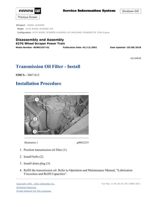
Illustration 1 g00822255
1. Position transmission oil filter (1).
2. Install bolts (2).
3. Install drain plug (3).
4. Refill the transmission oil. Refer to Operation and Maintenance Manual, "Lubrication
Viscosities and Refill Capacities".
Copyright 1993 - 2021 Caterpillar Inc.
All Rights Reserved.
Private Network For SIS Licensees.
Tue May 11 00:20:26 UTC+0800 2021
1/1(W)
w
2021/5/11
https://127.0.0.1/sisweb/sisweb/techdoc/techdoc_print_page.jsp?returnurl=/sisweb/sisw...
2. Shutdown SIS
Previous Screen
Product: WHEEL SCRAPER
Model: 627G WHEEL SCRAPER AYK
Configuration: 627G WHEEL SCRAPER AYK00001-UP (MACHINE) POWERED BY 3306 Engine
Disassembly and Assembly
627G Wheel Scraper Power Train
Media Number -RENR1557-02 Publication Date -01/12/2001 Date Updated -20/08/2018
i02047031
Transmission Electronic Control Module - Remove and
Install
SMCS - 3168-010
Removal Procedure
Start By:
a. Remove the hood. Refer to the Engine Supplement for the scraper Disassembly and
Assembly, "Hood - Remove and Install".
Note: Put identification marks on all hoses, on all hose assemblies on all wires, and on all tube
assemblies for installation purposes. Plug all hose assemblies and plug all tube assemblies. This
helps prevent fluid loss, and this helps keep contaminants from entering the system.
1. Turn the battery disconnect switch to the OFF position.
Illustration 1 g01050807
2. Disconnect harness assemblies (1).
3. Remove bolts (2) and transmission electronic control module (3).
1/2(W)
w
2021/5/11
https://127.0.0.1/sisweb/sisweb/techdoc/techdoc_print_page.jsp?returnurl=/sisweb/sisw...
3. Installation Procedure
Illustration 2 g01050807
1. Position transmission electronic control module (3) and install bolts (2).
2. Connect harness assemblies (1).
3. Turn the battery disconnect switch to the ON position.
End By:
a. Install the hood. Refer to the Engine Supplement for the scraper Disassembly and
Assembly, "Hood - Remove and Install".
Copyright 1993 - 2021 Caterpillar Inc.
All Rights Reserved.
Private Network For SIS Licensees.
Tue May 11 00:21:23 UTC+0800 2021
2/2(W)
w
2021/5/11
https://127.0.0.1/sisweb/sisweb/techdoc/techdoc_print_page.jsp?returnurl=/sisweb/sisw...
4. Shutdown SIS
Previous Screen
Product: WHEEL SCRAPER
Model: 627G WHEEL SCRAPER AYK
Configuration: 627G WHEEL SCRAPER AYK00001-UP (MACHINE) POWERED BY 3306 Engine
Disassembly and Assembly
627G Wheel Scraper Power Train
Media Number -RENR1557-02 Publication Date -01/12/2001 Date Updated -20/08/2018
i07349781
Transmission Hydraulic Control Valve - Remove and Install -
Scraper
SMCS - 3073-010
Removal Procedure
Illustration 1 g02691719
1. Disconnect hose assembly (1) and fittings (2). Remove clips (5). Remove bolts (3) and
cover (4).
1/4(W)
w
2021/5/11
https://127.0.0.1/sisweb/sisweb/techdoc/techdoc_print_page.jsp?returnurl=/sisweb/sisw...
6. Illustration 5 g02691836
Note: Take extra care when removing valves (12).
5. Remove plate (11) and valves (12) as a unit.
Illustration 6 g02691960
6. remove bolts (13) and shift cylinder assembly (14).
Illustration 7 g02691982
3/4(W)
w
2021/5/11
https://127.0.0.1/sisweb/sisweb/techdoc/techdoc_print_page.jsp?returnurl=/sisweb/sisw...
7. Illustration 8 g02692016
7. Remove bolts (16). Move valve body (15) away from tubes (17). Move valve body (15)
toward the front of the tractor. Remove valve body (15).
8. Remove three tubes (17). Remove O-ring seals (18) from three tubes (17).
Installation Procedure
1. Install valve body (15) in the reverse order of removal.
Copyright 1993 - 2021 Caterpillar Inc.
All Rights Reserved.
Private Network For SIS Licensees.
Tue May 11 00:22:20 UTC+0800 2021
4/4(W)
w
2021/5/11
https://127.0.0.1/sisweb/sisweb/techdoc/techdoc_print_page.jsp?returnurl=/sisweb/sisw...
8. Shutdown SIS
Previous Screen
Product: WHEEL SCRAPER
Model: 627G WHEEL SCRAPER AYK
Configuration: 627G WHEEL SCRAPER AYK00001-UP (MACHINE) POWERED BY 3306 Engine
Disassembly and Assembly
627G Wheel Scraper Power Train
Media Number -RENR1557-02 Publication Date -01/12/2001 Date Updated -20/08/2018
i02304746
Transmission Hydraulic Control Valve - Remove
SMCS - 3073-011
Removal Procedure
Start By:
a. Remove the hood. Refer to the engine supplement for the scraper Disassembly and
Assembly, "Hood - Remove and Install".
NOTICE
Care must be taken to ensure that fluids are contained during
performance of inspection, maintenance, testing, adjusting, and repair
of the product. Be prepared to collect the fluid with suitable containers
before opening any compartment or disassembling any component
containing fluids.
Refer to Special Publication, NENG2500, "Dealer Service Tool
Catalog" for tools and supplies suitable to collect and contain fluids on
Cat products.
Dispose of all fluids according to local regulations and mandates.
1. Drain the transmission oil into a suitable container for storage or disposal. The capacity of
the transmission is approximately 53 L (14 US gal).
1/4(W)
w
2021/5/11
https://127.0.0.1/sisweb/sisweb/techdoc/techdoc_print_page.jsp?returnurl=/sisweb/sisw...
9. Illustration 1 g01096780
Note: Do not disconnect any hose assemblies. Do not disconnect any harness assemblies.
2. Reposition harness assembly (2), harness assembly (3), and harness assembly (4) in order to
remove cover (1).
3. Remove cover (1).
Illustration 2 g00822714
4. Remove the gasket.
5. Remove bolts (5).
6. Remove transmission hydraulic control valve (6).
2/4(W)
w
2021/5/11
https://127.0.0.1/sisweb/sisweb/techdoc/techdoc_print_page.jsp?returnurl=/sisweb/sisw...
11. Copyright 1993 - 2021 Caterpillar Inc.
All Rights Reserved.
Private Network For SIS Licensees.
4/4(W)
w
2021/5/11
https://127.0.0.1/sisweb/sisweb/techdoc/techdoc_print_page.jsp?returnurl=/sisweb/sisw...
12. Shutdown SIS
Previous Screen
Product: WHEEL SCRAPER
Model: 627G WHEEL SCRAPER AYK
Configuration: 627G WHEEL SCRAPER AYK00001-UP (MACHINE) POWERED BY 3306 Engine
Disassembly and Assembly
627G Wheel Scraper Power Train
Media Number -RENR1557-02 Publication Date -01/12/2001 Date Updated -20/08/2018
i02310162
Transmission Hydraulic Control Valve - Disassemble
SMCS - 3073-015
Disassembly Procedure
Table 1
Required Tools
Tool Part Number Description Qty
A 1P-1853 Retaining Ring Pliers 1
Start By:
a. Remove the transmission hydraulic control valve. Refer to Disassembly and Assembly,
"Transmission Hydraulic Control Valve - Remove".
NOTICE
Care must be taken to ensure that fluids are contained during
performance of inspection, maintenance, testing, adjusting, and repair
of the product. Be prepared to collect the fluid with suitable containers
before opening any compartment or disassembling any component
containing fluids.
Refer to Special Publication, NENG2500, "Dealer Service Tool
Catalog" for tools and supplies suitable to collect and contain fluids on
Cat products.
Dispose of all fluids according to local regulations and mandates.
1/6(W)
w
2021/5/11
https://127.0.0.1/sisweb/sisweb/techdoc/techdoc_print_page.jsp?returnurl=/sisweb/sisw...
13. Note: Hold each cover securely in order to contain the spring pressure when you remove the
bolts.
Illustration 1 g01096879
Personal injury can result from being struck by parts propelled by a
released spring force.
Make sure to wear all necessary protective equipment.
Follow the recommended procedure and use all recommended tooling to
release the spring force.
1. Remove bolts (3) from cover (1).
2. Remove bolts (2A) from cover (2).
Illustration 2 g01034814
3. Remove cover (1) and cover (2). Remove piston (4). Remove spool (5).
2/6(W)
w
2021/5/11
https://127.0.0.1/sisweb/sisweb/techdoc/techdoc_print_page.jsp?returnurl=/sisweb/sisw...
14. Illustration 3 g01034815
Personal injury can result from being struck by parts propelled by a
released spring force.
Make sure to wear all necessary protective equipment.
Follow the recommended procedure and use all recommended tooling to
release the spring force.
4. Remove piston (4), spring (6), and spring (7). Remove spacers (8).
5. Remove slug (13).
6. Use Tooling (A) in order to remove retaining ring (12).
7. Remove retainer (11). Remove spring (10).
8. Remove plunger (9) from spool (5).
Illustration 4 g00822724
3/6(W)
w
2021/5/11
https://127.0.0.1/sisweb/sisweb/techdoc/techdoc_print_page.jsp?returnurl=/sisweb/sisw...
15. 9. Remove spool (14). Remove stop (15).
10. Remove spring (16).
11. Remove slug (20) and remove spool (19).
12. Remove spring (18). Remove washer (17).
Illustration 5 g01096790
13. Remove load spool (21). Remove speed spool (22).
Illustration 6 g01096791
14. If necessary, loosen locknuts (24) and remove links (23) from spools (21) and (22).
4/6(W)
w
2021/5/11
https://127.0.0.1/sisweb/sisweb/techdoc/techdoc_print_page.jsp?returnurl=/sisweb/sisw...
16. Illustration 7 g01096792
Personal injury can result from being struck by parts propelled by a
released spring force.
Make sure to wear all necessary protective equipment.
Follow the recommended procedure and use all recommended tooling to
release the spring force.
Note: Hold the cover securely in order to contain the spring pressure when you remove the
bolts.
15. Remove bolts (25) and cover (26).
Illustration 8 g01096793
Personal injury can result from being struck by parts propelled by a
released spring force.
Make sure to wear all necessary protective equipment.
Follow the recommended procedure and use all recommended tooling to
release the spring force.
16. Remove spring (29) and spool assembly (30).
17. Use Tooling (A) to remove retaining ring (34) from spool (30).
5/6(W)
w
2021/5/11
https://127.0.0.1/sisweb/sisweb/techdoc/techdoc_print_page.jsp?returnurl=/sisweb/sisw...
17. 18. Remove retainer (33), spring (32), and plunger (31).
19. If necessary, remove dowel (27) and remove stop (28).
Copyright 1993 - 2021 Caterpillar Inc.
All Rights Reserved.
Private Network For SIS Licensees.
Tue May 11 00:24:11 UTC+0800 2021
6/6(W)
w
2021/5/11
https://127.0.0.1/sisweb/sisweb/techdoc/techdoc_print_page.jsp?returnurl=/sisweb/sisw...
18. Shutdown SIS
Previous Screen
Product: WHEEL SCRAPER
Model: 627G WHEEL SCRAPER AYK
Configuration: 627G WHEEL SCRAPER AYK00001-UP (MACHINE) POWERED BY 3306 Engine
Disassembly and Assembly
627G Wheel Scraper Power Train
Media Number -RENR1557-02 Publication Date -01/12/2001 Date Updated -20/08/2018
i07349785
Transmission Hydraulic Control Valve - Disassemble -
Scraper
SMCS - 3073-015
Disassembly Procedure
Start By:
a. Remove the transmission hydraulic control valve (scraper).
Illustration 1 g02476779
Personal injury can result from being struck by parts propelled by a
released spring force.
Make sure to wear all necessary protective equipment.
1/5(W)
w
2021/5/11
https://127.0.0.1/sisweb/sisweb/techdoc/techdoc_print_page.jsp?returnurl=/sisweb/sisw...
19. Follow the recommended procedure and use all recommended tooling to
release the spring force.
Note: Hold each cover securely to contain the spring pressure when you remove the bolts.
1. Remove bolts (3) and cover (1).
2. Remove bolts (4) and cover (2).
Illustration 2 g02476780
Illustration 3 g02476827
3. Remove piston (5), spring (7), spring (8), spacers (9), and spool assembly (6).
4. Remove slug (14), retaining ring (13), retainer (12), spring (11), and plunger (10) from
spool assembly (6).
2/5(W)
w
2021/5/11
https://127.0.0.1/sisweb/sisweb/techdoc/techdoc_print_page.jsp?returnurl=/sisweb/sisw...
20. Illustration 4 g02476836
5. Remove spool (15), spring (18), washer (19), and spring (20).
6. Remove slug (22), spool (21), and spool (16).
Illustration 5 g02476838
7. Remove load spool (22) and speed spool (23).
Illustration 6 g02476839
8. If necessary, loosen locknuts (25) and remove links (24) from load spool (22) and speed
spool (23).
3/5(W)
w
2021/5/11
https://127.0.0.1/sisweb/sisweb/techdoc/techdoc_print_page.jsp?returnurl=/sisweb/sisw...
21. Illustration 7 g02476841
Illustration 8 g02476843
Personal injury can result from being struck by parts propelled by a
released spring force.
Make sure to wear all necessary protective equipment.
Follow the recommended procedure and use all recommended tooling to
release the spring force.
Note: Hold the cover securely to contain the spring pressure when you remove the bolts.
9. Remove bolts (26), cover (27), spring (30), and spool assembly (31).
10. Remove retaining ring (35), retainer (34), spring (33), and plunger (32) from spool assembly
(31).
11. If necessary, remove dowel (28) and stop (29).
4/5(W)
w
2021/5/11
https://127.0.0.1/sisweb/sisweb/techdoc/techdoc_print_page.jsp?returnurl=/sisweb/sisw...
22. Illustration 9 g06290432
12. Remove solenoid assemblies (30) and O-rings (31). Remove cover (32).
Illustration 10 g06290440
13. Loosen lock nut (35) and remove link (36) from valve spool (34). Remove valve spool (34),
retainer (33), and the ball from the body.
Copyright 1993 - 2021 Caterpillar Inc.
All Rights Reserved.
Private Network For SIS Licensees.
Tue May 11 00:25:08 UTC+0800 2021
5/5(W)
w
2021/5/11
https://127.0.0.1/sisweb/sisweb/techdoc/techdoc_print_page.jsp?returnurl=/sisweb/sisw...
23. Shutdown SIS
Previous Screen
Product: WHEEL SCRAPER
Model: 627G WHEEL SCRAPER AYK
Configuration: 627G WHEEL SCRAPER AYK00001-UP (MACHINE) POWERED BY 3306 Engine
Disassembly and Assembly
627G Wheel Scraper Power Train
Media Number -RENR1557-02 Publication Date -01/12/2001 Date Updated -20/08/2018
i02310163
Transmission Hydraulic Control Valve - Assemble
SMCS - 3073-016
Assembly Procedure
Table 1
Required Tools
Tool Part Number Description Qty
A 1P-1853 Retaining Ring Pliers 1
NOTICE
Keep all parts clean from contaminants.
Contamination of the hydraulic system with foreign material will
reduce the service life of the hydraulic system components.
To prevent contaminants from entering the hydraulic system, always
plug or cap the lines, fittings, or hoses as they are disconnected. Cover
any disassembled components and clean them properly before
assembly.
Clean the hydraulic system properly after any major component
exchange or especially after a component failure, to remove any
contamination.
1/6(W)
w
2021/5/11
https://127.0.0.1/sisweb/sisweb/techdoc/techdoc_print_page.jsp?returnurl=/sisweb/sisw...
24. Illustration 1 g01096793
Improper assembly of parts that are spring loaded can cause bodily
injury.
To prevent possible injury, follow the established assembly procedure
and wear protective equipment.
1. If necessary, install dowel (27) and install stop (28).
2. Install retainer (33), spring (32), and plunger (31).
3. Use Tooling (A) to install retaining ring (34) onto spool (30).
4. Install spring (29) and spool assembly (30).
Illustration 2 g01096792
2/6(W)
w
2021/5/11
https://127.0.0.1/sisweb/sisweb/techdoc/techdoc_print_page.jsp?returnurl=/sisweb/sisw...
25. Improper assembly of parts that are spring loaded can cause bodily
injury.
To prevent possible injury, follow the established assembly procedure
and wear protective equipment.
Note: Hold the cover securely while you install the bolts.
5. Position cover (26). Install bolts (25). Tighten bolts (25) to a torque of 30 ± 4 N·m
(22 ± 3 lb ft).
Illustration 3 g01096791
6. If necessary, install links (23) and tighten locknuts (24) onto spools (21) and (22).
Illustration 4 g01096790
7. Install load spool (21). Install speed spool (22).
3/6(W)
w
2021/5/11
https://127.0.0.1/sisweb/sisweb/techdoc/techdoc_print_page.jsp?returnurl=/sisweb/sisw...
26. Illustration 5 g00822724
8. Install spool (19). Install slug (20).
9. Install spring (18). Install washer (17).
10. Install spring (16).
11. Install spool (14). Install stop (15).
Illustration 6 g01034815
Improper assembly of parts that are spring loaded can cause bodily
injury.
To prevent possible injury, follow the established assembly procedure
and wear protective equipment.
12. Install plunger (9) to spool (5).
13. Install spring (10). Install retainer (11).
4/6(W)
w
2021/5/11
https://127.0.0.1/sisweb/sisweb/techdoc/techdoc_print_page.jsp?returnurl=/sisweb/sisw...
27. 14. Use Tooling (A) in order to install retaining ring (12).
15. Install slug (13).
16. Install spacers (8). Install spring (6), spring (7), and spool (4).
Illustration 7 g01034814
Illustration 8 g01096879
Improper assembly of parts that are spring loaded can cause bodily
injury.
To prevent possible injury, follow the established assembly procedure
and wear protective equipment.
17. Install spool (5). Install piston (4).
Note: Hold each cover securely while you tighten the bolts.
5/6(W)
w
2021/5/11
https://127.0.0.1/sisweb/sisweb/techdoc/techdoc_print_page.jsp?returnurl=/sisweb/sisw...
28. 18. Position cover (2). Install bolts (2A). Tighten bolts (2A) to a torque of 30 ± 4 N·m
(22 ± 3 lb ft).
19. Install cover (1). Install bolts (3). Tighten bolts (3) to a torque of 30 ± 4 N·m (22 ± 3 lb ft).
End By:
a. Install the transmission hydraulic control valve. Refer to Disassembly and Assembly,
"Transmission Hydraulic Control Valve - Install".
Copyright 1993 - 2021 Caterpillar Inc.
All Rights Reserved.
Private Network For SIS Licensees.
Tue May 11 00:26:03 UTC+0800 2021
6/6(W)
w
2021/5/11
https://127.0.0.1/sisweb/sisweb/techdoc/techdoc_print_page.jsp?returnurl=/sisweb/sisw...
29. Shutdown SIS
Previous Screen
Product: WHEEL SCRAPER
Model: 627G WHEEL SCRAPER AYK
Configuration: 627G WHEEL SCRAPER AYK00001-UP (MACHINE) POWERED BY 3306 Engine
Disassembly and Assembly
627G Wheel Scraper Power Train
Media Number -RENR1557-02 Publication Date -01/12/2001 Date Updated -20/08/2018
i07349808
Transmission Hydraulic Control Valve - Assemble - Scraper
SMCS - 3073-016
Assembly Procedure
Illustration 1 g06290462
1. Install retainer (39) in the body. Install ball (43) in the hole in retainer (39). Turn retainer
(39) until ball (43) falls into the pocket in the body. Install valve spool (40). Install lock nut
(41) onto link (42) and install link (42) on valve spool (40).
1/6(W)
w
2021/5/11
https://127.0.0.1/sisweb/sisweb/techdoc/techdoc_print_page.jsp?returnurl=/sisweb/sisw...
30. Illustration 2 g06290452
2. Install solenoids (36). Tighten the cartridge of the solenoid to a torque of 50 ± 5 N·m
(37 ± 4 lb ft). Tighten the nut that holds the coil assembly to a torque of 9.0 ± 0.5 N·m
(80 ± 5 lb in). Install O-rings (37). Be sure that the O-ring seals are in place on cover (38).
Install cover (38).
Illustration 3 g06290473
3. Adjust link (42) until Dimension (X) is 50.0 ± 0.8 mm (1.97 ± 0.032 inch). Tighten locknut
(41) to a torque of 34 ± 7 N·m (25 ± 5 lb ft).
Illustration 4 g02476843
2/6(W)
w
2021/5/11
https://127.0.0.1/sisweb/sisweb/techdoc/techdoc_print_page.jsp?returnurl=/sisweb/sisw...
31. Illustration 5 g02476841
Improper assembly of parts that are spring loaded can cause bodily
injury.
To prevent possible injury, follow the established assembly procedure
and wear protective equipment.
4. Install stop (29) and dowel (28).
5. Install plunger (32), spring (33), retainer (34), and retaining ring (35) into spool assembly
(31).
Note: Hold the cover securely while you install the bolts.
6. Install spool assembly (31), spring (30), cover (27), and bolts (26). Tighten bolts (26) to a
torque of 30 ± 4 N·m (22 ± 3 lb ft).
Illustration 6 g02476839
7. Install links (24) and tighten locknuts (25) onto load spool (22) and speed spool (23).
3/6(W)
w
2021/5/11
https://127.0.0.1/sisweb/sisweb/techdoc/techdoc_print_page.jsp?returnurl=/sisweb/sisw...
32. Illustration 7 g02476838
8. Install load spool (22) and speed spool (23).
Illustration 8 g02476836
9. Install spool (16), spool (21), and slug (22).
10. Install spring (20), washer (19), spring (18), and spool (15).
Illustration 9 g02476827
4/6(W)
w
2021/5/11
https://127.0.0.1/sisweb/sisweb/techdoc/techdoc_print_page.jsp?returnurl=/sisweb/sisw...
33. Suggest:
If the above button click is invalid.
Please download this document
first, and then click the above link
to download the complete manual.
Thank you so much for reading
34. Illustration 10 g02476780
11. Install plunger (10), spring (11), retainer (12), retaining ring (13), and slug (14) into spool
assembly (6).
12. Install washers (9), spool assembly (6), spring (8), spring (7), and piston (5).
Illustration 11 g02476779
Improper assembly of parts that are spring loaded can cause bodily
injury.
To prevent possible injury, follow the established assembly procedure
and wear protective equipment.
Note: Hold each cover securely while you tighten the bolts.
13. Install cover (2) and bolts (4). Tighten bolts (4) to a torque of 30 ± 4 N·m (22 ± 3 lb ft).
14. Install cover (1) and bolts (3). Tighten bolts (3) to a torque of 30 ± 4 N·m (22 ± 3 lb ft).
End By:
5/6(W)
w
2021/5/11
https://127.0.0.1/sisweb/sisweb/techdoc/techdoc_print_page.jsp?returnurl=/sisweb/sisw...
35. a. Install the transmission hydraulic control valve (scraper).
Copyright 1993 - 2021 Caterpillar Inc.
All Rights Reserved.
Private Network For SIS Licensees.
Tue May 11 00:26:58 UTC+0800 2021
6/6(W)
w
2021/5/11
https://127.0.0.1/sisweb/sisweb/techdoc/techdoc_print_page.jsp?returnurl=/sisweb/sisw...