
Recommended
More Related Content
Similar to Caterpillar Cat 3512E Marine Engine (Prefix SY3) Service Repair Manual Instant Download (SY300001 and up).pdf
Similar to Caterpillar Cat 3512E Marine Engine (Prefix SY3) Service Repair Manual Instant Download (SY300001 and up).pdf (15)
More from lunrizan628
More from lunrizan628 (20)
Recently uploaded
Recently uploaded (17)
Caterpillar Cat 3512E Marine Engine (Prefix SY3) Service Repair Manual Instant Download (SY300001 and up).pdf
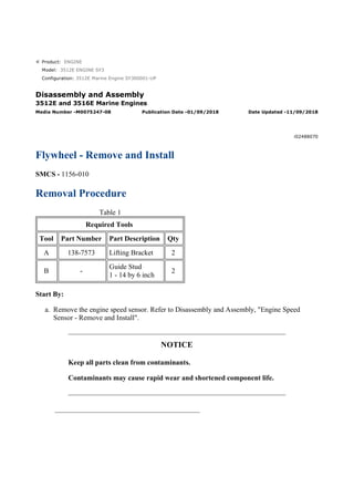
- 1. Product: ENGINE Model: 3512E ENGINE SY3 Configuration: 3512E Marine Engine SY300001-UP Disassembly and Assembly 3512E and 3516E Marine Engines Media Number -M0075247-08 Publication Date -01/09/2018 Date Updated -11/09/2018 i02488070 Flywheel - Remove and Install SMCS - 1156-010 Removal Procedure Table 1 Required Tools Tool Part Number Part Description Qty A 138-7573 Lifting Bracket 2 B - Guide Stud 1 - 14 by 6 inch 2 Start By: a. Remove the engine speed sensor. Refer to Disassembly and Assembly, "Engine Speed Sensor - Remove and Install". NOTICE Keep all parts clean from contaminants. Contaminants may cause rapid wear and shortened component life. 1/3(W) w 2022/4/3 https://127.0.0.1/sisweb/sisweb/techdoc/techdoc_print_page.jsp?returnurl=/sisweb/siswe...
- 2. Illustration 1 g01126776 1. Attach Tooling (A) and a suitable lifting device to flywheel (1). The weight of flywheel (1) is approximately 170 kg (375 lb). 2. Remove two bolts (2) on each side of the crankshaft and install Tooling (B). 3. Remove remaining bolts (2). 4. Remove flywheel (1). Note: If necessary, Use a prybar against Tooling (A) to remove the flywheel from the crankshaft. 5. Use a hammer and a punch in order to remove ring gear (3) from flywheel (1). Installation Procedure Table 2 Required Tools Tool Part Number Part Description Qty A 138-7573 Lifting Bracket 2 B - Guide Stud 1 - 14 by 6 inch 2 NOTICE Keep all parts clean from contaminants. Contaminants may cause rapid wear and shortened component life. 2/3(W) w 2022/4/3 https://127.0.0.1/sisweb/sisweb/techdoc/techdoc_print_page.jsp?returnurl=/sisweb/siswe...
- 3. Illustration 2 g01126776 1. Raise the temperature of new ring gear (3). Install the ring gear on flywheel (1). Ensure that the chamfer of the gear teeth will be toward the pinion of the starting motor. 2. Install Tooling (B) in the end of the crankshaft. 3. Attach Tooling (A) and a suitable lifting device to flywheel (1). The weight of flywheel (1) is approximately 170 kg (375 lb). 4. Lift the flywheel into position onto Tooling (B). Ensure that the mark on the flywheel is aligned with the mark on the crankshaft. 5. Apply clean engine oil to the threads of bolts (2). Install bolts (2). 6. Remove Tooling (A) and Tooling (B). Install remaining bolts (2). Tighten bolts (2) to a torque of 1150 ± 60 N·m (848 ± 44 lb ft). End By: a. Install the engine speed sensor. Refer to Disassembly and Assembly, "Engine Speed Sensor - Remove and Install". 3/3(W) w 2022/4/3 https://127.0.0.1/sisweb/sisweb/techdoc/techdoc_print_page.jsp?returnurl=/sisweb/siswe...
- 4. Product: ENGINE Model: 3512E ENGINE SY3 Configuration: 3512E Marine Engine SY300001-UP Disassembly and Assembly 3512E and 3516E Marine Engines Media Number -M0075247-08 Publication Date -01/09/2018 Date Updated -11/09/2018 i03565063 Crankshaft Rear Seal and Wear Sleeve - Remove SMCS - 1161-011; 7558-011 Removal Procedure Table 1 Required Tools Tool Part Number Part Description Qty A 1U-7600 Slide Hammer Puller 1 B 6V-3143 or 1U-7325 Distorter Adapter 1 C 5P-7409 Sleeve Distorter 1 Start By: A. Remove the flywheel. Refer to Disassembly and Assembly, "Flywheel - Remove and Install". NOTICE Keep all parts clean from contaminants. Contaminants may cause rapid wear and shortened component life. NOTICE 1/3(W) w 2022/4/3 https://127.0.0.1/sisweb/sisweb/techdoc/techdoc_print_page.jsp?returnurl=/sisweb/siswe...
- 5. Every time that the crankshaft seal is removed from the wear sleeve, a new wear sleeve and crankshaft seal must be installed. Illustration 1 g00659239 1. Drill three evenly spaced holes in crankshaft rear seal (1) . Use Tooling (A) in order to remove crankshaft rear seal (1) . Illustration 2 g00659240 2. Insert Tooling (B) between the rear housing and wear sleeve (2) . NOTICE The use of excessive force on the sleeve distorter can cause the distorter adapter to crack the housing. To help avoid damage to the engine, do not use excessive force to remove the wear sleeve. 2/3(W) w 2022/4/3 https://127.0.0.1/sisweb/sisweb/techdoc/techdoc_print_page.jsp?returnurl=/sisweb/siswe...
- 6. 3. Insert Tooling (C) between Tooling (B) and wear sleeve (2) . Carefully turn Tooling (C) until the edge of the tool causes a crease in wear sleeve (2) . Repeat this procedure several times around wear sleeve (2) until wear sleeve (2) can be removed by hand. 3/3(W) w 2022/4/3 https://127.0.0.1/sisweb/sisweb/techdoc/techdoc_print_page.jsp?returnurl=/sisweb/siswe...
- 7. Product: ENGINE Model: 3512E ENGINE SY3 Configuration: 3512E Marine Engine SY300001-UP Disassembly and Assembly 3512E and 3516E Marine Engines Media Number -M0075247-08 Publication Date -01/09/2018 Date Updated -11/09/2018 i06986865 Crankshaft Rear Seal and Wear Sleeve - Install SMCS - 1161-012; 7558-012 Installation Procedure For Seals 113-8432 and 113-8433 Table 1 Required Tools Tool Part Number Part Description Qty D 6V-4003 (1) Seal Locator As 1 2N-5006 ***#i06986865/i06603187.3*** Bolt 2 E 8T-3099 ***#i06986865/i06603187.3*** Seal Installer 1 F 9S-8858 ***#i06986865/i06603187.3*** Nut 1 G - (Loctite 620) - H 484-7863 (2) Tool As 1 (1) For installation of seals 113-8432 and 113-8433 (2) For Installation of seals 436-1478 and 436-1479 NOTICE Keep all parts clean from contaminants. Contaminants may cause rapid wear and shortened component life. Note: The crankshaft front seal and the wear sleeve must be replaced at the same time. Once the crankshaft front seal and the wear sleeve are separated, these components cannot be used again. 1/4(W) w 2022/4/3 https://127.0.0.1/sisweb/sisweb/techdoc/techdoc_print_page.jsp?returnurl=/sisweb/siswe...
- 8. Note: Do not use any type of lubricant during the installation of the crankshaft front seal and the wear sleeve. 1. Before installation of the crankshaft front seal and the wear sleeve, inspect the crankshaft for scratches. Also, inspect the crankshaft for any distortion on the surface that may lead to an out of round condition. Use a polishing cloth to remove any imperfections on the crankshaft. Illustration 1 g01136390 2. Clean the outside diameter of crankshaft (3) and the inside diameter of the new wear sleeve (2). Clean the bore for the crankshaft front seal in front housing (4).Apply Tooling (G) to the inner diameter of the wear sleeve and the surface of the crankshaft prior to assembly. 3. Install Tooling (D) on crankshaft (3). 4. Place crankshaft front seal (1) and wear sleeve (2) onto Tooling (D). 5. Position Tooling (E) onto Tooling (D). Lubricate the face of the washer on Tooling (F). Install Tooling (F) onto Tooling (E). Tighten Tooling (F) until Tooling (E) contacts Tooling (D). 6. Remove the Tooling from the crankshaft. 7. Check the crankshaft front seal and the wear sleeve for the correct installation. Installation Procedure For Seals 436-1478 and 436-1479 NOTICE Keep all parts clean from contaminants. Contaminants may cause rapid wear and shortened component life. 2/4(W) w 2022/4/3 https://127.0.0.1/sisweb/sisweb/techdoc/techdoc_print_page.jsp?returnurl=/sisweb/siswe...
- 9. NOTICE Do not place engine oil on the crankshaft seal for installation. Lubrication of the crankshaft seal can give a false indication of leakage at a later time. Note: Ensure that there are no imperfections on the mating surfaces of the crankshaft, the installation tooling, or on the sealing surface of the crankshaft. Surface imperfections can distort the seal during installation and will cause the seal to malfunction. Illustration 2 g06042396 1. Using Tooling (H), install rear seal (1) as outlined in the following steps: a. Install pilot (H1) to the crankshaft and install bolts (H2). b. Position rear seal (1) onto pilot (H1). c. Install driver (H3) onto the shaft of pilot (H1). Mark driver (H3) at the 12 O' Clock position. Install bearing (H4) and nut (H5). d. Tighten nut (H5) until the base of driver (H3) contacts the skirt of pilot (H1). Loosen nut (H5) and rotate driver (H3) 180 degree. Retighten nut (H5) until driver (H3) contacts the skirt of pilot (H1). 2. Remove Tooling (H). End By: a. Install the flywheel. 3/4(W) w 2022/4/3 https://127.0.0.1/sisweb/sisweb/techdoc/techdoc_print_page.jsp?returnurl=/sisweb/siswe...
- 10. Model: 3512E ENGINE SY3 Configuration: 3512E Marine Engine SY300001-UP Disassembly and Assembly 3512E and 3516E Marine Engines Media Number -M0075247-08 Publication Date -01/09/2018 Date Updated -11/09/2018 i06705117 Flywheel Housing - Remove SMCS - 1157-011 Removal Procedure Table 1 Required Tools Tool Part Number Part Description Qty A 238-9586 Camshaft Drive Group 1 B 8B-7548 Push-Puller Tool Group 1 8B-7559 Adapter 2 8B-7561 Step Plate 1 1P-0820 Hydraulic Puller 1 5H-1504 Hard Washer 3 9U-6600 Hand Hydraulic Pump 1 C 138-7573 Link Bracket 2 D - Guide Stud 5/8 - 11 by 6 inch 2 E Loctite 7649 - Start By: a. Remove the starting motor. Refer to Disassembly and Assembly, "Air Starting Motor - Remove". Refer to Disassembly and Assembly, "Electric Starting Motor - Remove and Install". 1/5(W) w 2022/4/3 https://127.0.0.1/sisweb/sisweb/techdoc/techdoc_print_page.jsp?returnurl=/sisweb/siswe...
- 11. b. If the exhaust elbow is attached to the flywheel housing, remove the exhaust elbow and remove the bracket for the exhaust elbow. Refer to Disassembly and Assembly, "Exhaust Elbow - Remove and Install". c. Remove the engine oil pan. Refer to Disassembly and Assembly, "Engine Oil Pan - Remove". d. Remove the engine speed sensor. Refer to Disassembly and Assembly, "Engine Speed Sensor - Remove and Install". e. Remove the engine speed/timing sensor. Refer to Disassembly and Assembly, "Engine Speed/Timing Sensor - Remove and Install". NOTICE Keep all parts clean from contaminants. Contaminants may cause rapid wear and shortened component life. Illustration 1 g01126909 1. Remove rear camshaft covers (1). 2. Remove timing pin (2) from the storage position. 3. Remove timing bolt (5) from the storage position. Remove cover (3) and plug (4) from the flywheel housing. 4. Use Tooling (A) to turn the flywheel in order to install timing bolt (5) in the flywheel and timing pin (2) in both camshafts. Refer to Testing and Adjusting, "Camshaft Timing". Refer to Testing and Adjusting, "Finding the Top Center Position for the No. 1 Piston". 2/5(W) w 2022/4/3 https://127.0.0.1/sisweb/sisweb/techdoc/techdoc_print_page.jsp?returnurl=/sisweb/siswe...
- 12. 5. Remove the timing bolt from the flywheel. 6. Remove the crankshaft rear seal and the wear sleeve. Refer to Disassembly and Assembly, "Crankshaft Rear Seal and Wear Sleeve - Remove". Illustration 2 g01126908 7. Remove tube (6). 8. Remove drain tubes (7) for the turbochargers. Remove the gaskets from the elbows. 9. Remove covers (8) and the gasket. Illustration 3 g01316299 10. Remove bolt (9) and plate (10). Place the three washers from Tooling (B) behind plate (10) and install bolt (9). Install Tooling (B) on camshaft drive gear (11). Apply 51675 kPa (7500 psi) to the puller. Strike the screw on the puller with a hammer until camshaft drive gear (11) is free from the camshaft. Remove Tooling (B) from the camshaft drive gear. Remove camshaft drive gear (11) from the camshaft. 3/5(W) w 2022/4/3 https://127.0.0.1/sisweb/sisweb/techdoc/techdoc_print_page.jsp?returnurl=/sisweb/siswe...
- 13. Note: Plate (10) must be installed in order to keep camshaft drive gear (11) on the camshaft during the removal procedure. Illustration 4 g01316301 11. Remove bolt (12). Remove ring (13). Illustration 5 g01316307 12. Place the three washers from Tooling (B) behind plate (10) and install bolt (12). Install Tooling (B) on camshaft drive gear (14). Use Tooling (B) in order to remove camshaft drive gear (14) from the camshaft. Apply 51675 kPa (7500 psi) to the puller. Strike the screw on the puller with a hammer until camshaft drive gear (14) is free from the camshaft. Remove Tooling (B) from the camshaft drive gear. Remove camshaft drive gear (14) from the camshaft. Note: Plate (10) must be installed in order to keep camshaft drive gear (14) on the camshaft during the removal procedure. 4/5(W) w 2022/4/3 https://127.0.0.1/sisweb/sisweb/techdoc/techdoc_print_page.jsp?returnurl=/sisweb/siswe...
- 14. Illustration 6 g01316311 13. Install Tooling (C) and a suitable lifting device on flywheel housing (16). The weight of flywheel housing (16) is approximately 235 kg (518 lb). 14. Remove two bolts (17) and install Tooling (D). Remove the remaining bolts (17) and remove flywheel housing (16) from the cylinder block. 15. If necessary, remove plugs (15) from the flywheel housing. Note: Ensure that the rear gear group and the crankshaft are properly protected during the cleaning procedure. Ensure that the bolts are cleaned with a wire brush in order to remove debris or residue. Ensure that the bores for the bolts in the cylinder block are tapped again. Ensure that the bores for the bolts are cleaned in order to remove debris or residue. 16. After removing flywheel housing (16), clean the mating surface of the cylinder block and the mating surface of the flywheel housing with Tooling (E). If necessary, use a gasket scraper and a solvent in order to remove any residual gasket material. Both mating surfaces must be clean, dry, and free of any oil before installation. 5/5(W) w 2022/4/3 https://127.0.0.1/sisweb/sisweb/techdoc/techdoc_print_page.jsp?returnurl=/sisweb/siswe...
- 15. Product: ENGINE Model: 3512E ENGINE SY3 Configuration: 3512E Marine Engine SY300001-UP Disassembly and Assembly 3512E and 3516E Marine Engines Media Number -M0075247-08 Publication Date -01/09/2018 Date Updated -11/09/2018 i07522043 Flywheel Housing - Install SMCS - 1157-012 Installation Procedure Table 1 Required Tools Tool Part Number Part Description Qty C 138-7573 Link Bracket 2 D - Guide Stud 5/8 - 11 by 6 inch 2 F -(1) Loctite 5127 - (1) EAME NOTICE Keep all parts clean from contaminants. Contaminants may cause rapid wear and shortened component life. NOTICE Do not turn the crankshaft or the camshaft while the camshaft gear is removed. If the front gear group is not correctly timed during installation, interference can occur between the pistons and the valves, resulting in damage to the engine. 1/6(W) w 2022/4/3 https://127.0.0.1/sisweb/sisweb/techdoc/techdoc_print_page.jsp?returnurl=/sisweb/siswe...
- 16. Note: Refer to Engine News, 27, March 2006, "Sealing and Installing the Flywheel Housing" for more information. 1. Ensure that the mating surfaces of the flywheel housing and the engine block are clean. Both mating surfaces must be clean, dry, and free of any oil before Tooling (F) is applied. Illustration 1 g01317446 2. Apply a 6.0 mm (0.25 inch) bead of Tooling (F) to the mating surface of the flywheel housing. Refer to Illustration 1. 2/6(W) w 2022/4/3 https://127.0.0.1/sisweb/sisweb/techdoc/techdoc_print_page.jsp?returnurl=/sisweb/siswe...
- 17. Illustration 2 g01316311 3. Install Tooling (D) into the cylinder block. 4. Install Tooling (C) and a suitable lifting device on flywheel housing (16). The weight of flywheel housing (16) is approximately 235 kg (518 lb). 5. Lift the flywheel housing into position onto Tooling (D). 6. Install bolts (17) and the hard washers that secure the flywheel housing to the cylinder block. Remove Tooling (D) and install remaining bolts (17) and the hard washers. Note: Refer to Parts Manual for the correct positions for bolts that secure the flywheel housing to the cylinder block. 7. Tighten bolts (17) evenly. Tighten the 1/2 - NC bolts to a torque of 135 ± 20 N·m (100 ± 15 lb ft). Tighten the 5/8 - NC bolts to a torque of 270 ± 40 N·m (200 ± 30 lb ft). 8. Tighten plugs (15) to a torque of 70 ± 15 N·m (50 ± 11 lb ft). 9. Install the crankshaft rear seal and the wear sleeve. Refer to Disassembly and Assembly, "Crankshaft Rear Seal and Wear Sleeve - Install". Illustration 3 g01140296 10. Install timing bolt (5) in the flywheel. Ensure that timing pin (2) is installed in each camshaft. Refer to Testing and Adjusting, "Camshaft Timing". Refer to Testing and Adjusting, "Finding the Top Center Position for the No. 1 Piston". 3/6(W) w 2022/4/3 https://127.0.0.1/sisweb/sisweb/techdoc/techdoc_print_page.jsp?returnurl=/sisweb/siswe...
- 18. Illustration 4 g01316352 Illustration 5 g01316354 11. Use the following procedure to install camshaft drive gear (11) and camshaft drive gear (14). a. Clean the taper of the camshaft and the tapered bore of the camshaft gear with a lint free cloth saturated with solvent to remove oil. Clean the parts again with a lint free alcohol wipe to remove any residue. The alcohol wipe will dirty after cleaning the parts. Clean the parts again with a lint free alcohol wipe until no residue is left on the alcohol wipe. Note: The taper of the camshaft and the tapered bore of the camshaft gear must be clean, dry, and free of residue before assembly. b. Ensure that the camshaft timing pins and the timing pin for the flywheel are installed. c. Place camshaft drive gear (11) and camshaft drive gear (14) in position. Remove the backlash by rotating the gears in the opposite direction of camshaft rotation. Note: For "Standard Rotation" engines, turn the camshaft drive gears COUNTERCLOCKWISE. For "Reverse Rotation" engines, turn the camshaft drive gears CLOCKWISE. d. Install bolt (9) and plate (10). 4/6(W) w 2022/4/3 https://127.0.0.1/sisweb/sisweb/techdoc/techdoc_print_page.jsp?returnurl=/sisweb/siswe...
- 19. e. Install bolt (12) and ring (13). Ensure that the hole in the ring is properly seated on the locating pin. f. Tighten the bolt to a torque of 360 N·m (265 lb ft). g. Place a mark on the bolt. h. Place a driver against the retaining plate of the camshaft drive gear. Strike the driver with a hammer, three times, or four times. i. Tighten the bolt again to a torque of 360 N·m (265 lb ft). j. Repeat Steps 11.h and 11.i until the mark has turned at least 90 degrees. Illustration 6 g01126909 12. Remove the timing pin from the camshafts. Install timing pin (2) in the storage position. Install rear camshaft covers (1). 13. Remove the timing bolt from the flywheel. Install plug (4) in the timing hole. Install cover (3) and timing bolt (5) in the storage position on the flywheel housing. 5/6(W) w 2022/4/3 https://127.0.0.1/sisweb/sisweb/techdoc/techdoc_print_page.jsp?returnurl=/sisweb/siswe...
- 20. Illustration 7 g01126908 14. Install tube (6) if equipped. 15. Install the gaskets on the elbows. Install drain tubes (7) for the turbochargers. 16. Install the gasket and covers (8) on the flywheel housing. End By: a. Install the engine speed/timing sensor. Refer to Disassembly and Assembly, "Engine Speed/Timing Sensor - Remove and Install". b. Install the engine speed sensor. Refer to Disassembly and Assembly, "Engine Speed Sensor - Remove and Install". c. Install the engine oil pan. Refer to Disassembly and Assembly, "Engine Oil Pan - Install". d. If the exhaust elbow was removed, install the exhaust elbow. Refer to Disassembly and Assembly, "Exhaust Elbow - Remove and Install". e. Install the starting motors. Refer to Disassembly and Assembly, "Air Starting Motor - Install". Refer to Disassembly and Assembly, "Electric Starting Motor - Remove and Install". 6/6(W) w 2022/4/3 https://127.0.0.1/sisweb/sisweb/techdoc/techdoc_print_page.jsp?returnurl=/sisweb/siswe...
- 21. Product: ENGINE Model: 3512E ENGINE SY3 Configuration: 3512E Marine Engine SY300001-UP Disassembly and Assembly 3512E and 3516E Marine Engines Media Number -M0075247-08 Publication Date -01/09/2018 Date Updated -11/09/2018 i07525193 Engine Oil Sequence Valves - Remove and Install SMCS - 1332-010 Removal Procedure Start By: a. Remove the front housing. Refer to Disassembly and Assembly, "Housing (Front) - Remove". b. Remove the flywheel housing. Refer to Disassembly and Assembly, "Flywheel Housing - Remove". NOTICE Keep all parts clean from contaminants. Contaminants may cause rapid wear and shortened component life. 1/7(W) w 2022/4/3 https://127.0.0.1/sisweb/sisweb/techdoc/techdoc_print_page.jsp?returnurl=/sisweb/siswe...
- 22. Illustration 1 g01135024 1. Remove bolts (1) and thrust plate (2). Remove balancer gear (3) from the balancer gear shaft. Note: The balancer gear is for the 3508C engine. The 3512C Engine, 3512E Engine, and the 3516C Engine do not have the balancer gear on the front of the engine. Illustration 2 g01135028 Personal injury can result from parts and/or covers under spring pressure. 2/7(W) w 2022/4/3 https://127.0.0.1/sisweb/sisweb/techdoc/techdoc_print_page.jsp?returnurl=/sisweb/siswe...
- 23. Suggest: For more complete manuals. Please go to the home page. https://www.ebooklibonline.com If the above button click is invalid. Please download this document first, and then click the above link to download the complete manual. Thank you so much for reading
- 24. Spring force will be released when covers are removed. Be prepared to hold spring loaded covers as the bolts are loosened. 2. Remove bolts (4) and cover (5) from the front of the cylinder block. 3. Remove plunger assembly (6) and spring (7) from the cylinder block. Illustration 3 g01135030 4. Remove bolts (12) and thrust plate (13). Remove cluster idler gear (14) from the rear of the cylinder block. 5. Remove bolts (8), idler shaft (9), camshaft idler gear (10), and thrust washer (11). 3/7(W) w 2022/4/3 https://127.0.0.1/sisweb/sisweb/techdoc/techdoc_print_page.jsp?returnurl=/sisweb/siswe...
- 25. Illustration 4 g01135029 Personal injury can result from parts and/or covers under spring pressure. Spring force will be released when covers are removed. Be prepared to hold spring loaded covers as the bolts are loosened. 6. Remove bolts (15) and cover (16) from the rear of the cylinder block. 7. Remove plunger assembly (17) and spring (18) from the cylinder block. Installation Procedure NOTICE Keep all parts clean from contaminants. Contaminants may cause rapid wear and shortened component life. Illustration 5 g01135029 4/7(W) w 2022/4/3 https://127.0.0.1/sisweb/sisweb/techdoc/techdoc_print_page.jsp?returnurl=/sisweb/siswe...