The document provides instructions for removing and installing the cylinder head of a 3046 engine. It describes:
1) Removing components like the turbocharger, rocker shaft, and fuel injectors to access the cylinder head.
2) Gradually removing the cylinder head bolts in reverse tightening order and lifting the head off using brackets.
3) Cleaning the cylinder head and block mating surfaces before installing a new gasket and replacing the head.
4) Reinstalling the head and tightening the bolts in the specified sequence before reinstalling other components.
Caterpillar cat 312 b excavator (prefix 6sw) service repair manual (6sw00001 ...fjsekksmemm
This document provides instructions for removing and installing the camshaft and camshaft gear on a 3054 engine. It describes:
1) Removing the rocker shaft, pushrods, fuel transfer pump, and front housing before removing the camshaft.
2) Using a puller tool to remove the camshaft gear after aligning timing marks.
3) Lubricating and carefully installing the camshaft, making sure not to damage lobes or bearings.
4) Cleaning and aligning the camshaft bearings before pressing them into place.
Caterpillar cat 312 b l excavator (prefix 6sw) service repair manual (6sw0000...fjsekksmemm
This document provides instructions for removing and installing the camshaft and camshaft gear on a 3054 engine. It describes:
1) Removing the rocker shaft, pushrods, fuel transfer pump, and front housing before removing the camshaft.
2) Using a puller tool to remove the camshaft gear after aligning timing marks.
3) Lubricating and carefully installing the camshaft, making sure not to damage lobes or bearings.
4) Cleaning and aligning the camshaft bearings before pressing them into place.
Caterpillar cat 320 d lrr excavator (prefix eby) service repair manual (eby00...fjkskedmme
This document provides instructions for removing and installing various components of an excavator engine, including:
1. Removing and installing the flywheel housing, which requires using lifting straps and removing bolts.
2. Removing and installing the crankshaft pulley, which requires using a puller and tightening a nut.
3. Removing the crankshaft front seal using a slide hammer puller and installing a new seal with an installer tool.
Caterpillar cat 320 d lrr excavator (prefix eby) service repair manual (eby00...fjskefksemer
The document provides instructions for removing and installing various engine components on Caterpillar 320D excavators, including:
1. Removing and installing the flywheel housing, which requires removing bolts and installing a new gasket.
2. Removing and installing the crankshaft pulley, which requires removing a nut and installing a washer and nut.
3. Removing the crankshaft front seal using a slide hammer puller and drilling holes in the seal.
Caterpillar Cat CP-433E Vibratory Compactor (Prefix BTY) Service Repair Manua...fjkskkedmm4r
This document provides instructions for disassembling and assembling the piston motor (axle propel) of a CP-433E vibratory compactor. The disassembly procedure involves removing 21 components from the housing in a specific order, taking care with spring-loaded parts. The assembly procedure reverses this process in 23 steps, ensuring proper installation of seals, bearings, pins and other components back into their original positions in the housing. Special tools and torque specifications are listed to correctly perform the work.
Caterpillar Cat CS-423E Vibratory Compactor (Prefix CFX) Service Repair Manua...fjkskkedmm4r
This document provides assembly instructions for the axle on a CS-423E vibratory compactor. It details 33 steps to assemble components such as the differential, wheel hubs, brakes, and gearbox. Tools and torque specifications are listed. Parts are cleaned and seals/bearings replaced if damaged before assembly. Components like the differential, wheel hubs, brakes, and gearbox are assembled separately then installed on the axle housing.
Caterpillar Cat CS-433E Vibratory Compactor (Prefix BTY) Service Repair Manua...fjkskkedmm4r
This document provides instructions for disassembling and assembling the piston motor (axle propel) of a CP-433E vibratory compactor. The disassembly procedure involves removing 21 components from the housing in a specific order, taking care with spring-loaded parts. The assembly procedure reverses this process in 23 steps, ensuring proper installation of seals, bearings, pins and other components back into their original positions in the housing. Special tools and torque specifications are listed to correctly perform the work.
Volvo EC55-2 Compact Excavator Parts Catalogue Manual – SN 5001 - 7620.pdffjkskkedmm4r
This document contains specifications for various engine parts for a Volvo EC55-2 engine. It includes sections for the engine, cylinder head, valves, pistons, connecting rods, camshaft, and other components. Each section lists the relevant part numbers, descriptions, quantities, and other details. The document provides an extensive catalogue of replacement parts for this engine model.
JCB 300T TRACKED Robot Parts Catalogue Manual (Serial Number 02427501-024278...fjkskkedmm4r
This document contains parts catalogs and diagrams for hydraulic components for an agricultural construction vehicle. It includes lists of parts with descriptions and quantities for hydraulic circuits, pumps, motors, tubing, valves, filters and other components. Pictures and diagrams show the layout and connections between various hydraulic system parts.
JCB 4CX444 (Sideshift AA AB Engine) BACKOHE LOADER Parts Catalogue Manual (Se...fjkskkedmm4r
This document contains parts listings and diagrams for engine components of a backhoe loader, including:
1. The block assembly diagram lists parts such as the cylinder block, liners, plugs, bolts, and rear seal housing.
2. The crankshaft assembly diagram lists the crankshaft, bearing kits, thrust washers, connecting rod assemblies, pistons, rings, and gears.
3. The document provides additional diagrams for components like the timing case, flywheel, and engine mountings. The parts are identified by part number, description, and quantity for various engine builds.
1) The document provides instructions to disassemble and assemble the final drive of a D9R track-type tractor.
2) It describes using various tools to remove over 30 components of the final drive including gears, shafts, seals, and hubs.
3) Precautions are included when using hydraulic cylinders and heated components to disassemble pieces.
1. The document provides instructions for removing and installing various engine components of a 3406C diesel engine, including the spacer plate, valves, valve seat inserts, bridge dowels, valve guides, oil pan and plate, oil pump, and piston cooling tubes.
2. The instructions describe cleaning and preparing surfaces, using specific tools to remove and install components, and ensuring proper installation and operation after reassembly.
3. The overall process involves removing engine components, cleaning surfaces, installing new parts as needed, and reassembling the engine, with the goal of properly servicing the 3406C diesel engine.
The document provides instructions for disassembling and assembling a recoil cylinder. Key steps include:
1. Removing the recoil cylinder and various components like bolts, guards, valves, and seals.
2. Inspecting parts and cleaning components as needed.
3. Reassembling the recoil cylinder by reinstalling components in reverse order and applying lubricants and seals. Precise torques are specified.
4. The process involves over 20 numbered steps and utilizes various specialized tools to properly disassemble and reassemble the recoil cylinder.
1. Remove the transmission, torque converter, and transfer gears from the tractor. Lift the assembly weighing approximately 1320 kg onto stands.
2. Attach lifting brackets and remove the bolts and nuts securing the 340 kg transfer gears to the transmission. Separate the transfer gears and remove o-rings.
3. Remove the final o-ring seal from the transmission. Install the transfer gears by reversing the removal steps.
This document provides assembly instructions for a final drive on an excavator. It involves assembling and installing several components in the following order: installing bearings and determining shim thickness; installing seals; installing dowel pins; installing the housing on the motor housing; installing coupling gear, bolts, and ring gear; assembling carrier assemblies; installing gears, shafts, and retaining rings; installing the cover and testing for leaks. The process requires precision measurements and uses several specialized tools to properly assemble the final drive.
The document provides instructions for removing and installing the drive shaft group with retarder on a 621E, 623E, or 627E tractor. It describes disconnecting hydraulic lines and removing bolts, covers, and housing to access the drive shaft group. Special care must be taken when removing plates and springs from the retarder, as they are under pressure. The process is reversed for installation, reconnecting hydraulic lines and refastening housings and covers.
This document provides step-by-step instructions to disassemble a piston pump. It begins by removing the piston pump and cleaning it. Key components like the piston assemblies, barrel assembly, springs and seals are then removed. Precision tools are required to remove parts like bearings and seals without damage. The multi-stage process dismantles both sides of the pump housing and internal components like valves, solenoids and control blocks are broken down. Precise part tracking and cleanliness are emphasized for reassembly.
This document provides instructions for disassembling and assembling bevel and transfer gears on a D6M track-type tractor. It outlines 22 steps for disassembly, which include removing brackets, yokes, carriers, cages, seals, bearings, gears, pins, shafts, and other components. It then outlines 21 steps for assembly, which involve cleaning parts, installing bearings, gears, pins, shafts, seals, covers, and other components in the reverse order of disassembly. Proper tools and cleaning procedures are emphasized to prevent damage to components from dirt and contaminants.
The document provides instructions for disassembling and assembling the steering clutch and brake of a D6N track-type tractor. It describes removing the final drive, steering clutch, and brake as separate components. It then details each step to disassemble the steering clutch and brake parts and housing. The corresponding assembly instructions are also provided in reverse order.
The document provides instructions for removing and installing various components of a 3406C diesel engine cylinder head. The procedures include removing and installing the cylinder head assembly, spacer plate, valves, valve seat inserts, bridge dowels, valve guides, and oil pan and plate. The instructions describe the specific steps to disassemble and reassemble each component.
This document provides disassembly and assembly instructions for a 3406C engine governor. It begins with removing the fuel injection pump housing and governor. It then provides 37 detailed steps for disassembling the governor components. The assembly section provides 43 steps for reassembling the governor in reverse order.
This document provides instructions for disassembling and assembling components of the retarder and bearing cage (drive shaft) of a 623G wheel tractor. The disassembly procedure involves using various tools to remove 15 different components. The assembly procedure instructs installing the components in reverse order and refers to other documents for installing related components. Safety notices are provided regarding containing fluids and preventing contamination.
1) The document provides assembly instructions for a final drive on an excavator.
2) It involves over 40 steps to assemble bearings, seals, gears, carriers, housing and cover components.
3) Special tools and procedures are required to set bearing preloads, install seals, and test for leaks. Proper torque values and sealants are specified.
Caterpillar Cat CB-534D VIBRATORY COMPACTOR (Prefix C8M) Service Repair Manua...fjkskkedmm4r
1. The document provides instructions for removing and installing a lifter group from a Caterpillar 3054C engine.
2. It lists the required tools which include a telescoping magnet.
3. The removal procedure involves first removing the camshaft, then using a magnet to remove the lifters from the cylinder block. Installation is the reverse of removal.
The document provides instructions for disassembling and assembling a swivel and swing motor on an excavator. Key steps include:
1. Removing bolts, seals and components to separate the swivel housing, rotor and cover.
2. Applying clean oil before reassembling components and installing seals, retainer and cover.
3. Draining swing motor oil before disconnecting hoses and removing bolts to detach the motor.
4. Dismantling the swing motor involves removing valves, seals, springs and using tools to separate internal components like pistons, plates and barrels.
Caterpillar Cat CB-335E Vibratory Compactor (Prefix C3F) Service Repair Manua...fjkskkedmm4r
This document provides instructions for removing the drum and drum support from a CB-335E vibratory compactor. It involves:
1. Removing the vibratory motor.
2. Disconnecting the water supply hose from the spray bar and removing the scraper and spray bar assembly.
3. Removing the drum support bolts and lifting the drum and drum support from the machine using lifting beams.
Caterpillar Cat CB-334E Vibratory Compactor (Prefix C3F) Service Repair Manua...fjkskkedmm4r
This document provides instructions for removing the drum and drum support from a CB-335E vibratory compactor. It involves:
1. Removing the vibratory motor.
2. Disconnecting the water supply hose from the spray bar and removing the scraper and spray bar assembly.
3. Removing the drum support bolts and lifting the drum and drum support from the machine using lifting beams.
Charging Fueling & Infrastructure (CFI) Program by Kevin MillerForth
Kevin Miller, Senior Advisor, Business Models of the Joint Office of Energy and Transportation gave this presentation at the Forth and Electrification Coalition CFI Grant Program - Overview and Technical Assistance webinar on June 12, 2024.
car rentals in nassau bahamas | atv rental nassau bahamasjustinwilson0857
At Dash Auto Sales & Car Rentals, we take pride in providing top-notch automotive services to residents and visitors alike in Nassau, Bahamas. Whether you're looking to purchase a vehicle, rent a car for your vacation, or embark on an exciting ATV adventure, we have you covered with our wide range of options and exceptional customer service.
Website: www.dashrentacarbah.com
Top-Quality AC Service for Mini Cooper Optimal Cooling PerformanceMotor Haus
Ensure your Mini Cooper stays cool and comfortable with our top-quality AC service. Our expert technicians provide comprehensive maintenance, repairs, and performance optimization, guaranteeing reliable cooling and peak efficiency. Trust us for quick, professional service that keeps your Mini Cooper's air conditioning system in top condition, ensuring a pleasant driving experience year-round.
Dahua provides a comprehensive guide on how to install their security camera systems. Learn about the different types of cameras and system components, as well as the installation process.
EV Charging at MFH Properties by Whitaker JamiesonForth
Whitaker Jamieson, Senior Specialist at Forth, gave this presentation at the Forth Addressing The Challenges of Charging at Multi-Family Housing webinar on June 11, 2024.
Real-time driver monitoring is one of the easiest ways to make fleet management efficient as well as seamless. Connected vehicle solutions such as fleet GPS trackers and associated software help businesses in several ways. Refer to the post below for more details.
Charging and Fueling Infrastructure Grant: Round 2 by Brandt HertensteinForth
Brandt Hertenstein, Program Manager of the Electrification Coalition gave this presentation at the Forth and Electrification Coalition CFI Grant Program - Overview and Technical Assistance webinar on June 12, 2024.
Caterpillar Cat 317B L Excavator (Prefix 9WW) Service Repair Manual (9WW00001 and up).pdf
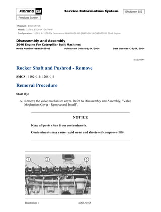
1. Shutdown SIS
Previous Screen
Product: EXCAVATOR
Model: 317B L EXCAVATOR 9WW
Configuration: 317B L & 317B LN Excavators 9WW00001-UP (MACHINE) POWERED BY 3046 Engine
Disassembly and Assembly
3046 Engine For Caterpillar Built Machines
Media Number -SENR6458-05 Publication Date -01/04/2004 Date Updated -22/04/2004
i01030044
Rocker Shaft and Pushrod - Remove
SMCS - 1102-011; 1208-011
Removal Procedure
Start By:
A. Remove the valve mechanism cover. Refer to Disassembly and Assembly, "Valve
Mechanism Cover - Remove and Install".
NOTICE
Keep all parts clean from contaminants.
Contaminants may cause rapid wear and shortened component life.
Illustration 1 g00530465
1/2
317B L & 317B LN Excavators 9WW00001-UP (MACHINE) POWERED BY 3046 E...
2020/12/10
https://127.0.0.1/sisweb/sisweb/techdoc/techdoc_print_page.jsp?returnurl=/sis...
2. 1. Loosen adjusting screws (1) on rocker arms.
2. Loosen six short bolts (3) and the washers on the rocker arm brackets.
3. Loosen six rocker bracket bolts (2) .
Note: Rocker bracket bolts are the longer bolts.
4. Remove six rocker bracket bolts (2) from the rocker arm brackets.
5. Remove six short bolts (3) and the washers from the rocker arm brackets.
6. Remove the rocker shaft assembly.
Illustration 2 g00530467
7. Put identification marks on pushrods (4) in order to identify the location of the pushrods in
the engine. Remove pushrods (4) .
Copyright 1993 - 2020 Caterpillar Inc.
All Rights Reserved.
Private Network For SIS Licensees.
Thu Dec 10 23:00:45 UTC+0800 2020
2/2
317B L & 317B LN Excavators 9WW00001-UP (MACHINE) POWERED BY 3046 E...
2020/12/10
https://127.0.0.1/sisweb/sisweb/techdoc/techdoc_print_page.jsp?returnurl=/sis...
3. Shutdown SIS
Previous Screen
Product: EXCAVATOR
Model: 317B L EXCAVATOR 9WW
Configuration: 317B L & 317B LN Excavators 9WW00001-UP (MACHINE) POWERED BY 3046 Engine
Disassembly and Assembly
3046 Engine For Caterpillar Built Machines
Media Number -SENR6458-05 Publication Date -01/04/2004 Date Updated -22/04/2004
i02063400
Rocker Shaft - Disassemble
SMCS - 1123-015
Disassembly Procedure
Table 1
Required Tools
Tool Part Number Part Description Qty
A 1P-1855 Retaining Ring Pliers 1
Start By:
A. Remove the rocker shaft and pushrods. Refer to Disassembly and Assembly, "Rocker Shaft
and Pushrod - Remove".
NOTICE
Keep all parts clean from contaminants.
Contaminants may cause rapid wear and shortened component life.
1/2
317B L & 317B LN Excavators 9WW00001-UP (MACHINE) POWERED BY 3046 E...
2020/12/10
https://127.0.0.1/sisweb/sisweb/techdoc/techdoc_print_page.jsp?returnurl=/sis...
4. Illustration 1 g00531311
1. Use Tool (A) to remove snap ring (1) on each end of the rocker shaft assembly.
Illustration 2 g00531306
2. Remove twelve rockers (2), six rocker arm shaft brackets (4) and six springs (3) from each
end of shaft assembly (5) .
Note: Mark the location and the position of each component for later assembly.
3. Remove plugs (6) from each end of shaft assembly (5) .
Copyright 1993 - 2020 Caterpillar Inc.
All Rights Reserved.
Private Network For SIS Licensees.
Thu Dec 10 23:01:41 UTC+0800 2020
2/2
317B L & 317B LN Excavators 9WW00001-UP (MACHINE) POWERED BY 3046 E...
2020/12/10
https://127.0.0.1/sisweb/sisweb/techdoc/techdoc_print_page.jsp?returnurl=/sis...
5. Shutdown SIS
Previous Screen
Product: EXCAVATOR
Model: 317B L EXCAVATOR 9WW
Configuration: 317B L & 317B LN Excavators 9WW00001-UP (MACHINE) POWERED BY 3046 Engine
Disassembly and Assembly
3046 Engine For Caterpillar Built Machines
Media Number -SENR6458-05 Publication Date -01/04/2004 Date Updated -22/04/2004
i02063398
Rocker Shaft - Assemble
SMCS - 1102-016
Assembly Procedure
Table 1
Required Tools
Tool Part Number Part Description Qty
A 1P-1855 Retaining Ring Pliers 1
NOTICE
Keep all parts clean from contaminants.
Contaminants may cause rapid wear and shortened component life.
1/2
317B L & 317B LN Excavators 9WW00001-UP (MACHINE) POWERED BY 3046 E...
2020/12/10
https://127.0.0.1/sisweb/sisweb/techdoc/techdoc_print_page.jsp?returnurl=/sis...
6. Illustration 1 g00531306
1. Install twelve rockers (2), six rocker arm shaft brackets (4) and six springs (3) onto shaft
assembly (5) .
2. Install plugs (6) into each end of shaft assembly (5) .
Illustration 2 g00531311
3. Use Tool (A) to install snap ring (1) on each end of the rocker shaft assembly.
End By: Install the rocker shaft and pushrods. Refer to Disassembly and Assembly, "Rocker Shaft
and Pushrods - Install".
Copyright 1993 - 2020 Caterpillar Inc.
All Rights Reserved.
Private Network For SIS Licensees.
Thu Dec 10 23:02:37 UTC+0800 2020
2/2
317B L & 317B LN Excavators 9WW00001-UP (MACHINE) POWERED BY 3046 E...
2020/12/10
https://127.0.0.1/sisweb/sisweb/techdoc/techdoc_print_page.jsp?returnurl=/sis...
7. Shutdown SIS
Previous Screen
Product: EXCAVATOR
Model: 317B L EXCAVATOR 9WW
Configuration: 317B L & 317B LN Excavators 9WW00001-UP (MACHINE) POWERED BY 3046 Engine
Disassembly and Assembly
3046 Engine For Caterpillar Built Machines
Media Number -SENR6458-05 Publication Date -01/04/2004 Date Updated -22/04/2004
i01579663
Rocker Shaft and Pushrod - Install
SMCS - 1102-012; 1208-012
Installation Procedure
NOTICE
Keep all parts clean from contaminants.
Contaminants may cause rapid wear and shortened component life.
Illustration 1 g00530467
1. Install pushrods (4) .
1/2
317B L & 317B LN Excavators 9WW00001-UP (MACHINE) POWERED BY 3046 E...
2020/12/10
https://127.0.0.1/sisweb/sisweb/techdoc/techdoc_print_page.jsp?returnurl=/sis...
8. Note: Ensure that the pushrods are installed in the original location and seated in the valve
lifters correctly.
Illustration 2 g00530465
2. Install the rocker shaft assembly.
3. Install six rocker bracket bolts (2) and tighten the rocker bracket bolts to a torque of 15 ± 5
N·m (11 ± 4 lb ft).
Note: Rocker bracket bolts are the longer bolts.
4. Install six short bolts (3) and the washers. Tighten the short bolts to a torque of 15 ± 5 N·m
(11 ± 4 lb ft).
5. Adjust the inlet valve lash and the exhaust valve lash to 0.25 mm (0.010 inch). Refer to
Testing and Adjusting, "Air Inlet and Exhaust System" for more information on setting the
valve lash. Tighten adjusting screws (1) .
End By: Install the valve mechanism cover. Refer to Disassembly and Assembly, "Valve
Mechanism Cover - Remove and Install".
Copyright 1993 - 2020 Caterpillar Inc.
All Rights Reserved.
Private Network For SIS Licensees.
Thu Dec 10 23:03:33 UTC+0800 2020
2/2
317B L & 317B LN Excavators 9WW00001-UP (MACHINE) POWERED BY 3046 E...
2020/12/10
https://127.0.0.1/sisweb/sisweb/techdoc/techdoc_print_page.jsp?returnurl=/sis...
9. Shutdown SIS
Previous Screen
Product: EXCAVATOR
Model: 317B L EXCAVATOR 9WW
Configuration: 317B L & 317B LN Excavators 9WW00001-UP (MACHINE) POWERED BY 3046 Engine
Disassembly and Assembly
3046 Engine For Caterpillar Built Machines
Media Number -SENR6458-05 Publication Date -01/04/2004 Date Updated -22/04/2004
i01032735
Cylinder Head - Remove
SMCS - 1100-011
Removal Procedure
Start By:
A. Remove the turbocharger. Refer to Disassembly and Assembly, "Turbocharger - Remove".
B. Remove the rocker shaft and pushrods. Refer to Disassembly and Assembly, "Rocker Shaft
and Pushrods - Remove".
C. Remove the fuel injection nozzles in order to protect from damage. Refer to Disassembly
and Assembly, "Fuel Injection Nozzles - Remove".
D. Remove the glow plugs in order to protect from damage. Refer to Disassembly and
Assembly, "Glow Plugs - Remove and Install".
NOTICE
Keep all parts clean from contaminants.
Contaminants may cause rapid wear and shortened component life.
NOTICE
Care must be taken to ensure that fluids are contained during
performance of inspection, maintenance, testing, adjusting and repair
of the machine. Be prepared to collect the fluid with suitable containers
before opening any compartment or disassembling any component
containing fluids.
1/3
317B L & 317B LN Excavators 9WW00001-UP (MACHINE) POWERED BY 3046 E...
2020/12/10
https://127.0.0.1/sisweb/sisweb/techdoc/techdoc_print_page.jsp?returnurl=/sis...
10. Refer to Special Publication, NENG2500, "Caterpillar Tools and Shop
Products Guide", for tools and supplies suitable to collect and contain
fluids in Caterpillar machines.
Dispose of all fluids according to local regulations and mandates.
Illustration 1 g00562585
1. If necessary, remove bolt (2) and remove oil tube assembly (dipstick).
Illustration 2 g00531679
Cylinder Head Tightening Sequence
2. Gradually remove 25 cylinder head bolts (1) in reverse order of the tightening sequence.
2/3
317B L & 317B LN Excavators 9WW00001-UP (MACHINE) POWERED BY 3046 E...
2020/12/10
https://127.0.0.1/sisweb/sisweb/techdoc/techdoc_print_page.jsp?returnurl=/sis...
11. Note: Do not use a pry bar to separate the cylinder head from the engine block.
Illustration 3 g00560287
3. Attach a hoist to the cylinder head lifting brackets and remove the cylinder head from the
cylinder block. The weight of the cylinder head assembly is 60 kg (132 lb).
Note: Place the cylinder head on a surface that will not damage the face of the cylinder
head.
Illustration 4 g00560297
4. Remove the cylinder head gasket (3) .
Copyright 1993 - 2020 Caterpillar Inc.
All Rights Reserved.
Private Network For SIS Licensees.
Thu Dec 10 23:04:29 UTC+0800 2020
3/3
317B L & 317B LN Excavators 9WW00001-UP (MACHINE) POWERED BY 3046 E...
2020/12/10
https://127.0.0.1/sisweb/sisweb/techdoc/techdoc_print_page.jsp?returnurl=/sis...
12. Shutdown SIS
Previous Screen
Product: EXCAVATOR
Model: 317B L EXCAVATOR 9WW
Configuration: 317B L & 317B LN Excavators 9WW00001-UP (MACHINE) POWERED BY 3046 Engine
Disassembly and Assembly
3046 Engine For Caterpillar Built Machines
Media Number -SENR6458-05 Publication Date -01/04/2004 Date Updated -22/04/2004
i02063403
Cylinder Head - Install
SMCS - 1100-012
Installation Procedure
Table 1
Required Tools
Tool Part Number Part Description Qty
A 9U-7995 Guide Pin 2
NOTICE
Keep all parts clean from contaminants.
Contaminants may cause rapid wear and shortened component life.
1/3
317B L & 317B LN Excavators 9WW00001-UP (MACHINE) POWERED BY 3046 E...
2020/12/10
https://127.0.0.1/sisweb/sisweb/techdoc/techdoc_print_page.jsp?returnurl=/sis...
13. Illustration 1 g00560297
1. Clean the surfaces of the cylinder head and the cylinder block that are in contact with each
other. Ensure that the surfaces are clean and dry. Install a new, dry cylinder head gasket (3)
on the cylinder block.
Note: Do not use any sealant or gasket adhesive on the cylinder head gasket .
2. Install Tool (A) (not shown) on the cylinder block in order to install the cylinder head.
Illustration 2 g00560287
3. Attach a hoist to the cylinder head lifting brackets and install the cylinder head in position
on the cylinder block. The weight of the cylinder head assembly is 60 kg (132 lb).
4. Remove Tool (A) .
5. Apply 6V-4876 Lubricant to all of the threads and thrust faces of cylinder head bolts (1) .
Illustration 3 g00562585
2/3
317B L & 317B LN Excavators 9WW00001-UP (MACHINE) POWERED BY 3046 E...
2020/12/10
https://127.0.0.1/sisweb/sisweb/techdoc/techdoc_print_page.jsp?returnurl=/sis...
14. Illustration 4 g00531679
Cylinder Head Tightening Sequence
6. Install cylinder head bolts (1) and tighten all of the bolts (1 through 25) in a numerical order
according to the cylinder head tightening sequence. Tighten cylinder head bolts (1) to a
torque of 118 ± 5 N·m (87 ± 4 lb ft).
7. If necessary, install oil tube assembly (dipstick) and install bolt (2) .
End By:
a. Install the fuel injector nozzles. Refer to Disassembly and Assembly, "Fuel Injection
Nozzles - Install".
b. Install the glow plugs. Refer to Disassembly and Assembly, "Glow Plugs - Remove and
Install".
c. Install the rocker shaft and pushrods. Refer to Disassembly and Assembly, "Rocker Shaft
and Pushrods - Install".
d. Install the turbocharger. Refer to Disassembly and Assembly, "Turbocharger - Install".
Copyright 1993 - 2020 Caterpillar Inc.
All Rights Reserved.
Private Network For SIS Licensees.
Thu Dec 10 23:05:24 UTC+0800 2020
3/3
317B L & 317B LN Excavators 9WW00001-UP (MACHINE) POWERED BY 3046 E...
2020/12/10
https://127.0.0.1/sisweb/sisweb/techdoc/techdoc_print_page.jsp?returnurl=/sis...
15. Shutdown SIS
Previous Screen
Product: EXCAVATOR
Model: 317B L EXCAVATOR 9WW
Configuration: 317B L & 317B LN Excavators 9WW00001-UP (MACHINE) POWERED BY 3046 Engine
Disassembly and Assembly
3046 Engine For Caterpillar Built Machines
Media Number -SENR6458-05 Publication Date -01/04/2004 Date Updated -22/04/2004
i01033379
Lifter Group - Remove and Install
SMCS - 1209-010
Removal Procedure
Start By:
A. Remove the camshaft. Refer to Disassembly and Assembly, "Camshaft - Remove and
Install".
NOTICE
Keep all parts clean from contaminants.
Contaminants may cause rapid wear and shortened component life.
Illustration 1 g00532246
1/3
317B L & 317B LN Excavators 9WW00001-UP (MACHINE) POWERED BY 3046 E...
2020/12/10
https://127.0.0.1/sisweb/sisweb/techdoc/techdoc_print_page.jsp?returnurl=/sis...
16. Illustration 2 g00532061
1. Use a magnet to remove valve lifter (1), as shown. Put identification marks on the valve
lifters for installation purposes.
2. Repeat Step 1 for the remainder of the valve lifters.
Installation Procedure
NOTICE
Keep all parts clean from contaminants.
Contaminants may cause rapid wear and shortened component life.
Illustration 3 g00532061
1. Put 8T-2998 Lubricant on valve lifter (1) prior to installation. Install valve lifter (1) in the
original location in the cylinder block.
2/3
317B L & 317B LN Excavators 9WW00001-UP (MACHINE) POWERED BY 3046 E...
2020/12/10
https://127.0.0.1/sisweb/sisweb/techdoc/techdoc_print_page.jsp?returnurl=/sis...
17. 2. Repeat Step 1 for the remainder of the valve lifters.
End By: Install the camshaft. Refer to Disassembly and Assembly, "Camshaft - Remove and
Install".
Copyright 1993 - 2020 Caterpillar Inc.
All Rights Reserved.
Private Network For SIS Licensees.
Thu Dec 10 23:06:20 UTC+0800 2020
3/3
317B L & 317B LN Excavators 9WW00001-UP (MACHINE) POWERED BY 3046 E...
2020/12/10
https://127.0.0.1/sisweb/sisweb/techdoc/techdoc_print_page.jsp?returnurl=/sis...
18. Shutdown SIS
Previous Screen
Product: EXCAVATOR
Model: 317B L EXCAVATOR 9WW
Configuration: 317B L & 317B LN Excavators 9WW00001-UP (MACHINE) POWERED BY 3046 Engine
Disassembly and Assembly
3046 Engine For Caterpillar Built Machines
Media Number -SENR6458-05 Publication Date -01/04/2004 Date Updated -22/04/2004
i01597409
Camshaft - Remove and Install
SMCS - 1210-010
Removal Procedure 1
Table 1
Required Tools
Tool Part Number Part Description Qty
A 1P-2320 Combination Puller 1
C 1P-2321 Combination Puller 1
9S-9153 Puller Jaws 3
Start By:
A. Remove the timing gear cover. Refer to Disassembly and Assembly, "Housing (Front) -
Remove".
B. Remove the rocker shaft assembly and the pushrods. Refer to Disassembly and Assembly,
"Rocker Shaft and Pushrod - Remove".
C. Remove the oil pan. Refer to Disassembly and Assembly, "Engine Oil Pan - Remove and
Install".
Note: The engine oil pan is facing in the up direction in order to retain the lifters in position for
this procedure.
NOTICE
Keep all parts clean from contaminants.
Contaminants may cause rapid wear and shortened component life.
1/10
317B L & 317B LN Excavators 9WW00001-UP (MACHINE) POWERED BY 3046 E...
2020/12/10
https://127.0.0.1/sisweb/sisweb/techdoc/techdoc_print_page.jsp?returnurl=/sis...
19. NOTICE
Care must be taken to ensure that fluids are contained during
performance of inspection, maintenance, testing, adjusting and repair
of the product. Be prepared to collect the fluid with suitable containers
before opening any compartment or disassembling any component
containing fluids.
Refer to Special Publication, NENG2500, "Caterpillar Tools and Shop
Products Guide" for tools and supplies suitable to collect and contain
fluids on Caterpillar products.
Dispose of all fluids according to local regulations and mandates.
Note: Ensure that the marks on the timing gears are in alignment. Align the fuel injection drive
gear with the "33" mark with the "3" mark on the idler gear. Make an alignment of the "2" mark
on the camshaft gear with the "22" mark on the idler gear. Align the "1" mark on the crankshaft
gear with the "11" mark on the idler gear. The No. 1 cylinder is at the top center position when
these marks are in alignment.
1. Rotate the engine at 180 degrees.
Illustration 1 g00532179
2. Use Tool (A) to remove bearing (1) from the front of camshaft gear (2) .
Note: This step is necessary only if the camshaft gear is equipped with a bearing.
2/10
317B L & 317B LN Excavators 9WW00001-UP (MACHINE) POWERED BY 3046 E...
2020/12/10
https://127.0.0.1/sisweb/sisweb/techdoc/techdoc_print_page.jsp?returnurl=/sis...
20. Illustration 2 g00532382
NOTICE
Do not damage the lobes or the bearings when the camshaft is removed
or installed.
3. Position camshaft gear (2) so that the gear's slots align from the top to the bottom. Remove
two bolts (3) and the washers that hold thrust plate (4). Carefully remove the camshaft, the
thrust plate and the camshaft gear as an assembly.
4. Remove the 12 valve lifters. Refer to Disassembly and Assembly, "Lifter Group - Remove
and Install".
Illustration 3 g00532384
5. Use tool (C) to remove camshaft gear (2) from camshaft (5). Remove thrust plate (4) .
Installation Procedure 1
3/10
317B L & 317B LN Excavators 9WW00001-UP (MACHINE) POWERED BY 3046 E...
2020/12/10
https://127.0.0.1/sisweb/sisweb/techdoc/techdoc_print_page.jsp?returnurl=/sis...
21. Note: In this installation procedure, the engine needs to remain in the upside-down position in
order to keep the lifters in position while the camshaft is installed.
NOTICE
Keep all parts clean from contaminants.
Contaminants may cause rapid wear and shortened component life.
Note: During installation, ensure that camshaft (4) is clean and lubricate all of the
components with clean engine oil.
Illustration 4 g00532385
1. Install thrust plate (4) onto camshaft (5) .
Always wear protective gloves when handling parts that have been
heated.
2. Heat camshaft gear (2) in an oven to a maximum temperature of 150 °C (302 °F) and install
camshaft gear (2) onto camshaft (5) .
3. Install the 12 valve lifters. Refer to Disassembly and Assembly, "Lifter Group - Remove
and Install".
Note: During installation, ensure that the marks on the timing gears are in alignment. Align
the fuel injection drive gear with the "33" mark with the "3" mark on the idler gear. Make an
alignment of the "2" mark on the camshaft gear with the "22" mark on the idler gear. Align
4/10
317B L & 317B LN Excavators 9WW00001-UP (MACHINE) POWERED BY 3046 E...
2020/12/10
https://127.0.0.1/sisweb/sisweb/techdoc/techdoc_print_page.jsp?returnurl=/sis...
22. the "1" mark on the crankshaft gear with the "11" mark on the idler gear. The No. 1 cylinder
is at the top center position when these marks are in alignment.
4. Carefully install the camshaft assembly into the original location in the cylinder block.
Note: Caution must be used when the camshaft is installed in order to not damage the
camshaft lobe or the camshaft bearings.
Illustration 5 g00532382
5. Position camshaft gear (2) so that the gear's slots align from the top to the bottom. Install
two bolts (3) and the washers that hold thrust plate (4). Tighten bolts (3) to a torque of 10 to
13 N·m (7 to 10 lb ft).
6. If necessary, install the bearing onto the front of the camshaft gear.
End By:
a. Install the oil pan. Refer to Disassembly and Assembly, "Engine Oil Pan - Remove and
Install".
b. Install the rocker shaft assembly and the pushrods. Refer to Disassembly and Assembly,
"Rocker Shaft and Pushrod - Install".
c. Install the timing gear cover. Refer to Disassembly and Assembly, "Housing (Front) -
Install".
Removal Procedure 2
Table 2
Required Tools
Tool Part Number Part Description Qty
A 1P-2320 Combination Puller 1
B 1U-7638 Magnetic Holding Tools 12
C 1P-2321 Combination Puller 1
9S-9153 Puller Jaws 3
5/10
317B L & 317B LN Excavators 9WW00001-UP (MACHINE) POWERED BY 3046 E...
2020/12/10
https://127.0.0.1/sisweb/sisweb/techdoc/techdoc_print_page.jsp?returnurl=/sis...
23. Start By:
A. Remove the timing gear cover. Refer to Disassembly and Assembly, " Housing (Front) -
Remove".
B. Remove the cylinder head. Refer to Disassembly and Assembly, "Cylinder Head -
Remove".
Note: This removal procedure is done with the engine in the upright position and the valve lifters
left in the cylinder block.
NOTICE
Keep all parts clean from contaminants.
Contaminants may cause rapid wear and shortened component life.
NOTICE
Care must be taken to ensure that fluids are contained during
performance of inspection, maintenance, testing, adjusting and repair
of the product. Be prepared to collect the fluid with suitable containers
before opening any compartment or disassembling any component
containing fluids.
Refer to Special Publication, NENG2500, "Caterpillar Tools and Shop
Products Guide" for tools and supplies suitable to collect and contain
fluids on Caterpillar products.
Dispose of all fluids according to local regulations and mandates.
6/10
317B L & 317B LN Excavators 9WW00001-UP (MACHINE) POWERED BY 3046 E...
2020/12/10
https://127.0.0.1/sisweb/sisweb/techdoc/techdoc_print_page.jsp?returnurl=/sis...
24. Illustration 6 g00532179
The engine is rotated at 180 degrees.
1. Use Tool (A) to remove bearing (1) from the front of camshaft gear (2) .
Note: This step is necessary only if the camshaft gear is equipped with a bearing.
Illustration 7 g00534616
2. Install Tool (B) in order to hold the 12 valve lifters.
Note: Make sure that Tool (B) is holding the lifters as far up in cylinder block (6) as
possible.
Illustration 8 g00534473
Note: Be careful not to dislodge the valve lifters from Tools (B) during removal of the
camshaft.
NOTICE
7/10
317B L & 317B LN Excavators 9WW00001-UP (MACHINE) POWERED BY 3046 E...
2020/12/10
https://127.0.0.1/sisweb/sisweb/techdoc/techdoc_print_page.jsp?returnurl=/sis...
25. Please write to us.
Our email:
aservicemanualpdf@yahoo.com
Please go to the homepage
to get the full manual, or
other brand PDF manuals.
Home Site:
aservicemanualpdf.com
26. Thank you very much for
your reading. Please Click
Here. Then Get COMPLETE
MANUAL. NO WAITING
NOTE:
If there is no response to
click on the link above,
please download the PDF
document first and then
click on it.
GET MORE OTHER MANUALS https://www.aservicemanualpdf.com/
27. Do not damage the lobes or the bearings when the camshaft is removed
or installed.
3. Position camshaft gear (2) so that the gear's slots align from the top to the bottom. Remove
two bolts (3) and the washers that hold thrust plate (4). Carefully remove the camshaft, the
thrust plate and the camshaft gear as an assembly from cylinder block (6) .
Illustration 9 g00532384
4. Use tool (C) to remove camshaft gear (2) from camshaft (5). Remove thrust plate (4) .
Installation Procedure 2
Table 3
Required Tools
Tool Part Number Part Description Qty
B 1U-7638 Magnetic Holding Tools 12
Note: This installation procedure is done with the engine in the upright position and the valve
lifters left in the cylinder block.
NOTICE
Keep all parts clean from contaminants.
Contaminants may cause rapid wear and shortened component life.
Note: During installation, ensure that camshaft (4) is clean and lubricate all of the
components with clean engine oil.
8/10
317B L & 317B LN Excavators 9WW00001-UP (MACHINE) POWERED BY 3046 E...
2020/12/10
https://127.0.0.1/sisweb/sisweb/techdoc/techdoc_print_page.jsp?returnurl=/sis...
28. Illustration 10 g00532385
1. Install thrust plate (4) onto camshaft (5). Heat camshaft gear (2) to a maximum temperature
of 150 °C (302 °F) and install camshaft gear (2) onto camshaft (4) .
Note: During installation, ensure that the marks on the timing gears are in alignment. Align
the fuel injection drive gear with the "33" mark with the "3" mark on the idler gear. Make an
alignment of the "2" mark on the camshaft gear with the "22" mark on the idler gear. Align
the "1" mark on the crankshaft gear with the "11" mark on the idler gear. The No. 1 cylinder
is at the top center position when these marks are in alignment.
2. Carefully install the camshaft assembly into the original location in the cylinder block.
Note: Caution must be used when the camshaft is installed in order to not damage the
camshaft lobe or the camshaft bearings.
Illustration 11 g00534616
Note: Make sure that Tool (B ) is holding the lifters as far up in cylinder block (6) as
possible.
9/10
317B L & 317B LN Excavators 9WW00001-UP (MACHINE) POWERED BY 3046 E...
2020/12/10
https://127.0.0.1/sisweb/sisweb/techdoc/techdoc_print_page.jsp?returnurl=/sis...
29. Illustration 12 g00534473
3. Position camshaft gear (2) so that the gear's slots align from the top to the bottom. Install
two bolts (3) and the washers that hold thrust plate (4). Tighten bolts (3) to a torque of 10 to
13 N·m (7 to 10 lb ft).
4. If necessary, install the bearing onto the front of the camshaft gear.
End By:
a. Install the cylinder head. Refer to Disassembly and Assembly, "Cylinder Head - Install".
b. Install the timing gear cover. Refer to Disassembly and Assembly, "Housing (Front) -
Install".
Copyright 1993 - 2020 Caterpillar Inc.
All Rights Reserved.
Private Network For SIS Licensees.
Thu Dec 10 23:07:16 UTC+0800 2020
10/10
317B L & 317B LN Excavators 9WW00001-UP (MACHINE) POWERED BY 304...
2020/12/10
https://127.0.0.1/sisweb/sisweb/techdoc/techdoc_print_page.jsp?returnurl=/sis...