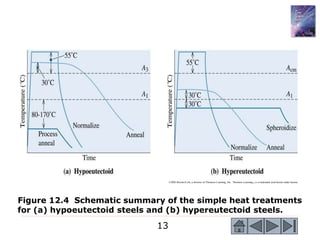
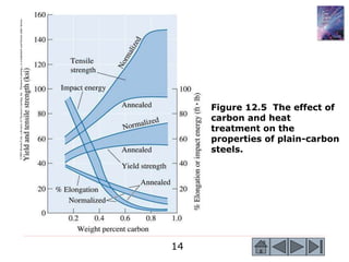
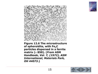
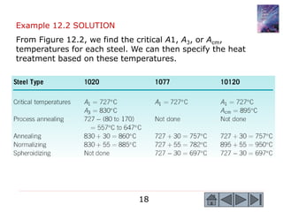
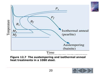
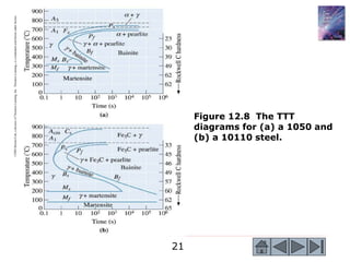
1
The Science and Engineering
of Materials, 4th ed
Donald R. Askeland – Pradeep P. Phulé
Chapter 12 – Ferrous Alloys
2
Objectives of Chapter 12
 Discuss how to use the eutectoid reaction
to control the structure and properties of
steels through heat treatment and alloying.
 Examine two special classes of ferrous
alloys: stainless steels and cast irons.
3
Chapter Outline
 12.1 Designations and Classification
of Steels
 12.2 Simple Heat Treatments
 12.3 Isothermal Heat Treatments
 12.4 Quench and Temper Heat
Treatments
 12.5 Effect of Alloying Elements
 12.6 Application of Hardenability
4
 12.7 Specialty Steels
 12.8 Surface Treatments
 12.9 Weldability of Steel
 12.10 Stainless Steels
 12.11 Cast Irons
Chapter Outline (Continued)
5
Figure 12.1 (a) In a blast furnace,
iron ore is reduced using coke
(carbon) and air to produce liquid
pig iron. The high-carbon content
in the pig iron is reduce by
introducing oxygen into the basic
oxygen furnace to produce liquid
steel. An electric arc furnace can
be used to produce liquid steel by
melting scrap. (b) Schematic of a
blast furnace operation. (Source:
www.steel.org. Used with
permission of the American Iron
and Steel Institute.)
6
 Designations - The AISI (American Iron and Steel
Institute) and SAE (Society of Automotive Engineers)
provide designation systems for steels that use a four- or
five-digit number.
 Classifications - Steels can be classified based on their
composition or the way they have been processed.
Section 12.1
Designations and Classification
of Steels
7
©2003
Brooks/Cole,
a
division
of
Thomson
Learning,
Inc.
Thomson
Learning
™
is
a
trademark
used
herein
under
license.
Figure 12.2 (a) The
eutectoid portion of
the Fe-Fe3C phase
diagram. (b) An
expanded version of
the Fe-C diagram,
adapted from
several sources.
8
Figure 12.3 Electron micrographs of (a) pearlite, (b)
bainite, and (c) tempered martensite, illustrating the
differences in cementite size and shape among these
three microconstituents ( 7500). (From The Making,
Shaping, and Treating of Steel, 10th Ed. Courtesy of
the Association of Iron and Steel Engineers.)
9
10
An unalloyed steel tool used for machining aluminum
automobile wheels has been found to work well, but the
purchase records have been lost and you do not know the
steel’s composition. The microstructure of the steel is
tempered martensite, and assume that you cannot estimate
the composition of the steel from the structure. Design a
treatment that may help determine the steel’s carbon
content.
Example 12.1
Design of a Method to Determine
AISI Number
11
Example 12.1 SOLUTION
The first way is to heat the steel to a temperature just below
the A1 temperature and hold for a long time. The steel
overtempers and large Fe3C spheres form in a ferrite matrix.
We then estimate the amount of ferrite and cementite and
calculate the carbon content using the lever law. If we measure
16% Fe3C using this method, the carbon content is:
%
086
.
1
or
16
100
)
0218
.
0
67
.
6
(
)
0218
.
0
(
C
Fe
% 3 










 x
x
A better approach, however, is to heat the steel above
the Acm to produce all austenite. If the steel then cools slowly,
it transforms to pearlite and a primary microconstituent. If,
when we do this, we estimate that the structure contains 95%
pearlite and 5% primary Fe3C, then:
%
065
.
1
or
95
100
77
.
0
67
.
6
-
6.67
Pearlite
% 









 x
x
12
 Process Annealing — Eliminating Cold Work: A low-
temperature heat treatment used to eliminate all or part
of the effect of cold working in steels.
 Annealing and Normalizing — Dispersion Strengthening:
Annealing - A heat treatment used to produce a soft,
coarse pearlite in steel by austenitizing, then furnace
cooling. Normalizing - A simple heat treatment obtained
by austenitizing and air cooling to produce a fine pearlitic
structure.
 Spheroidizing — Improving Machinability: Spheroidite - A
microconstituent containing coarse spheroidal cementite
particles in a matrix of ferrite, permitting excellent
machining characteristics in high-carbon steels.
Section 12.2
Simple Heat Treatments
13
©2003 Brooks/Cole, a division of Thomson Learning, Inc. Thomson Learning™ is a trademark used herein under license.
Figure 12.4 Schematic summary of the simple heat treatments
for (a) hypoeutectoid steels and (b) hypereutectoid steels.
14
©2003
Brooks/Cole,
a
division
of
Thomson
Learning,
Inc.
Thomson
Learning
™
is
a
trademark
used
herein
under
license.
Figure 12.5 The effect of
carbon and heat
treatment on the
properties of plain-carbon
steels.
15
Figure 12.6 The microstructure
of spheroidite, with Fe3C
particles dispersed in a ferrite
matrix ( 850). (From ASM
Handbook, Vol. 7, (1972), ASM
International, Materials Park,
OH 44073.)
16
Recommend temperatures for the process annealing,
annealing, normalizing, and spheroidizing of 1020,
1077, and 10120 steels.
Example 12.2
Determination of Heat Treating
Temperatures
17
©2003
Brooks/Cole,
a
division
of
Thomson
Learning,
Inc.
Thomson
Learning
™
is
a
trademark
used
herein
under
license.
Figure 12.2 (a) The
eutectoid portion of
the Fe-Fe3C phase
diagram. (b) An
expanded version of
the Fe-C diagram,
adapted from
several sources.
18
Example 12.2 SOLUTION
From Figure 12.2, we find the critical A1, A3, or Acm,
temperatures for each steel. We can then specify the heat
treatment based on these temperatures.
19
 Austempering - The isothermal heat treatment by which
austenite transforms to bainite.
 Isothermal annealing - Heat treatment of a steel by
austenitizing, cooling rapidly to a temperature between
the A1 and the nose of the TTT curve, and holding until
the austenite transforms to pearlite.
Section 12.3
Isothermal Heat Treatments
20
©2003 Brooks/Cole, a division of Thomson Learning, Inc. Thomson Learning™ is a trademark used herein under license.
Figure 12.7 The austempering and isothermal anneal
heat treatments in a 1080 steel.
21
©2003
Brooks/Cole,
a
division
of
Thomson
Learning,
Inc.
Thomson
Learning
™
is
a
trademark
used
herein
under
license.
Figure 12.8 The TTT
diagrams for (a) a 1050 and
(b) a 10110 steel.
22
A heat treatment is needed to produce a uniform
microstructure and hardness of HRC 23 in a 1050 steel axle.
Example 12.3
Design of a Heat Treatment for an Axle
©2003
Brooks/Cole,
a
division
of
Thomson
Learning,
Inc.
Thomson
Learning
™
is
a
trademark
used
herein
under
license.
Figure 12.8 The TTT
diagrams for (a) a 1050
and (b) a 10110 steel.
23
©2003
Brooks/Cole,
a
division
of
Thomson
Learning,
Inc.
Thomson
Learning
™
is
a
trademark
used
herein
under
license.
Figure 12.2 (a) The
eutectoid portion of
the Fe-Fe3C phase
diagram. (b) An
expanded version of
the Fe-C diagram,
adapted from
several sources.
24
Example 12.3 SOLUTION
1. Austenitize the steel at 770 + (30 to 55) = 805o
C to
825o
C, holding for 1 h and obtaining 100% γ.
2. Quench the steel to 600o
C and hold for a minimum of 10 s.
Primary ferrite begins to precipitate from the unstable
austenite after about 1.0 s. After 1.5 s, pearlite begins to
grow, and the austenite is completely transformed to
ferrite and pearlite after about 10 s. After this treatment,
the microconstituents present are:
%
64
100
)
0218
.
0
77
.
0
(
0.0218)
(0.5
Pearlite
%
36
100
)
0218
.
0
77
.
0
(
0.5)
(0.77
α
Primary






















3. Cool in air-to-room temperature, preserving the
equilibrium amounts of primary ferrite and pearlite. The
microstructure and hardness are uniform because of the
isothermal anneal.
25
©2003
Brooks/Cole,
a
division
of
Thomson
Learning,
Inc.
Thomson
Learning
™
is
a
trademark
used
herein
under
license.
Figure 12.9 Producing
complicated structures
by interrupting the
isothermal heat
treatment of a 1050
steel.
26
Figure 12.10 Dark feathers of
bainite surrounded by light
martensite, obtained by
interrupting the isothermal
transformation process ( 1500).
(ASM Handbook, Vol. 9
Metallography and Microstructure
(1985), ASM International,
Materials Park, OH 44073.)
27
 Retained austenite - Austenite that is unable to
transform into martensite during quenching because of
the volume expansion associated with the reaction.
 Tempered martensite - The microconstituent of ferrite
and cementite formed when martensite is tempered.
 Quench cracks - Cracks that form at the surface of a
steel during quenching due to tensile residual stresses
that are produced because of the volume change that
accompanies the austenite-to-martensite transformation.
 Marquenching - Quenching austenite to a temperature
just above the MS and holding until the temperature is
equalized throughout the steel before further cooling to
produce martensite.
Section 12.4
Quench and Temper Heat Treatments
28
©2003
Brooks/Cole,
a
division
of
Thomson
Learning,
Inc.
Thomson
Learning
™
is
a
trademark
used
herein
under
license.
Figure 12.11 The
effect of tempering
temperature on the
mechanical
properties of a 1050
steel.
29
Example 12.4
Design of a Quench and
Temper Treatment
A rotating shaft that delivers power from an electric motor is
made from a 1050 steel. Its yield strength should be at least
145,000 psi, yet it should also have at least 15% elongation in
order to provide toughness. Design a heat treatment to
produce this part.
Example 12.4 SOLUTION
1. Austenitize above the A3 temperature of 770o
C for 1 h.
An appropriate temperature may be 770 + 55 = 825o
C.
2. Quench rapidly to room temperature. Since the Mf is
about 250o
C, martensite will form.
3. Temper by heating the steel to 440o
C. Normally, 1 h will
be sufficient if the steel is not too thick.
4. Cool to room temperature.
30
Figure 12.12 Retained austenite
(white) trapped between
martensite needles (black)
( 1000). (From ASM Handbook,
Vol. 8, (1973), ASM International,
Materials Park, OH 44073.)
31
©2003
Brooks/Cole,
a
division
of
Thomson
Learning,
Inc.
Thomson
Learning
™
is
a
trademark
used
herein
under
license.
Figure 12.13
Increasing carbon
reduces the Ms and
Mf temperatures in
plain-carbon steels.
32
©2003 Brooks/Cole, a division of Thomson Learning, Inc. Thomson Learning™ is a trademark used herein under license.
Figure 12.14 Formation of quench cracks caused by residual
stresses produced during quenching. The figure illustrates
the development of stresses as the austenite transforms to
martensite during cooling.
33
©2003
Brooks/Cole,
a
division
of
Thomson
Learning,
Inc.
Thomson
Learning
™
is
a
trademark
used
herein
under
license.
Figure 12.15 The
marquenching heat
treatment designed
to reduce residual
stresses ands quench
cracking.
34
35
©2003 Brooks/Cole, a division of Thomson Learning, Inc. Thomson Learning™ is a trademark used herein under license.
Figure 12.16 The CCT diagram (solid lines) for a 1080 steel
compared with the TTT diagram (dashed lines).
36
©2003 Brooks/Cole, a division of Thomson Learning, Inc. Thomson Learning™ is a trademark used herein under license.
Figure 12.17 The CCT diagram for a low-alloy, 0.2% C Steel.
37
 Hardenability - Alloy steels have high hardenability.
 Effect on the Phase Stability - When alloying elements
are added to steel, the binary Fe-Fe3C stability is
affected and the phase diagram is altered.
 Shape of the TTT Diagram - Ausforming is a
thermomechanical heat treatment in which austenite is
plastically deformed below the A1 temperature, then
permitted to transform to bainite or martensite.
 Tempering - Alloying elements reduce the rate of
tempering compared with that of a plain-carbon steel.
Section 12.5
Effect of Alloying Elements
38
©2003
Brooks/Cole,
a
division
of
Thomson
Learning,
Inc.
Thomson
Learning
™
is
a
trademark
used
herein
under
license.
Figure 12.18 (a) TTT and (b)
CCT curves for a 4340 steel.
39
©2003
Brooks/Cole,
a
division
of
Thomson
Learning,
Inc.
Thomson
Learning
™
is
a
trademark
used
herein
under
license.
Figure 12.19 The
effect of 6%
manganese on the
stability ranges of
the phases in the
eutectoid portion of
the Fe-Fe3C phase
diagram.
40
©2003 Brooks/Cole, a division of Thomson Learning, Inc. Thomson Learning™ is a trademark used herein under license.
Figure 12.20 When alloying elements introduce a bay
region into the TTT diagram, the steel can be ausformed.
41
©2003 Brooks/Cole, a division of Thomson Learning, Inc. Thomson Learning™ is a trademark used herein under license.
Figure 12.21 The effect of alloying elements on the phases
formed during the tempering of steels. The air-hardenable
steel shows a secondary hardening peak.
42
 Jominy test - The test used to evaluate hardenability. An
austenitized steel bar is quenched at one end only, thus
producing a range of cooling rates along the bar.
 Hardenability curves - Graphs showing the effect of the
cooling rate on the hardness of as-quenched steel.
 Jominy distance - The distance from the quenched end of
a Jominy bar. The Jominy distance is related to the
cooling rate.
Section 12.6
Application of Hardenability
43
©2003 Brooks/Cole, a division of Thomson Learning, Inc. Thomson Learning™ is a trademark used herein under
license.
Figure 12.22 The set-up for the Jominy test used for
determining the hardenability of a steel.
44
©2003
Brooks/Cole,
a
division
of
Thomson
Learning,
Inc.
Thomson
Learning
™
is
a
trademark
used
herein
under
license.
Figure 12.23 The
hardenability curves
for several steels.
45
46
A gear made from 9310 steel, which has an as-quenched
hardness at a critical location of HRC 40, wears at an excessive
rate. Tests have shown that an as-quenched hardness of at
least HRC 50 is required at that critical location. Design a steel
that would be appropriate.
Example 12.5
Design of a Wear-Resistant Gear
©2003
Brooks/Cole,
a
division
of
Thomson
Learning,
Inc.
Thomson
Learning
™
is
a
trademark
used
herein
under
license.
Figure 12.23 The
hardenability curves for
several steels.
47
48
Example 12.5 SOLUTION
From Figure 12.23, a hardness of HRC 40 in a 9310 steel
corresponds to a Jominy distance of 10/16 in. (10o
C/s). If we
assume the same Jominy distance, the other steels shown in
Figure 12.23 have the following hardnesses at the critical
location:
1050 HRC 28 1080 HRC 36 4320 HRC 31
8640 HRC 52 4340 HRC 60
In Table 12-1, we find that the 86xx steels contain less alloying
elements than the 43xx steels; thus the 8640 steel is probably
less expensive than the 4340 steel and might be our best
choice. We must also consider other factors such as durability.
49
©2003 Brooks/Cole, a division of Thomson Learning, Inc. Thomson Learning™ is a trademark used herein under license.
Figure 12.24 The Grossman chart used to determine the
hardenability at the center of a steel bar for different
quenchants.
50
Design a quenching process to produce a minimum hardness of
HRC 40 at the center of a 1.5-in. diameter 4320 steel bar.
Example 12.6
Design of a Quenching Process
51
©2003 Brooks/Cole, a division of Thomson Learning, Inc. Thomson Learning™ is a trademark used herein under license.
Figure 12.24 The Grossman chart used to determine the
hardenability at the center of a steel bar for different
quenchants.
52
©2003
Brooks/Cole,
a
division
of
Thomson
Learning,
Inc.
Thomson
Learning
™
is
a
trademark
used
herein
under
license.
Figure 12.23 The
hardenability curves
for several steels.
53
Example 12.6 SOLUTION
Several quenching media are listed in Table 12-2. We can find
an approximate H coefficient for each of the quenching media,
then use Figure 12.24 to estimate the Jominy distance in a 1.5-
in. diameter bar for each media. Finally, we can use the
hardenability curve (Figure 12.23) to find the hardness in the
4320 steel. The results are listed below.
The last three methods, based on brine or agitated water, are
satisfactory. Using an unagitated brine quenchant might be least
expensive, since no extra equipment is needed to agitate the
quenching bath. However, H2O is less corrosive than the brine
quenchant.
54
 Tool steels - A group of high-carbon steels that provide
combinations of high hardness, toughness, or resistance
to elevated temperatures.
 Secondary hardening peak - Unusually high hardness in
a steel tempered at a high temperature caused by the
precipitation of alloy carbides.
 Dual-phase steels - Special steels treated to produce
martensite dispersed in a ferrite matrix.
 Maraging steels - A special class of alloy steels that
obtain high strengths by a combination of the
martensitic and age-hardening reactions.
Section 12.7
Specialty Steels
55
Figure 12.25 Microstructure of a
dual-phase steel, showing islands
of light martensite in a ferrite
matrix ( 2500). (From G. Speich,
‘‘Physical Metallurgy of Dual-Phase
Steels,’’ Fundamentals of Dual-
Phase Steels, The Metallurgical
Society of AIME, 1981.)
56
 Selectively Heating the Surface - Rapidly heat the
surface of a medium-carbon steel above the A3
temperature and then quench the steel.
 Case depth - The depth below the surface of a steel at
which hardening occurs by surface hardening and
carburizing processes.
 Carburizing - A group of surface-hardening techniques
by which carbon diffuses into steel.
 Cyaniding - Hardening the surface of steel with carbon
and nitrogen obtained from a bath of liquid cyanide
solution.
 Carbonitriding - Hardening the surface of steel with
carbon and nitrogen obtained from a special gas
atmosphere.
Section 12.8
Surface Treatments
57
©2003 Brooks/Cole, a division of Thomson Learning, Inc. Thomson Learning™ is a trademark used herein under license.
Figure 12.26 (a) Surface hardening by localized heating. (b)
Only the surface heats above the A1 temperature and is
quenched to martensite.
58
©2003 Brooks/Cole, a division of Thomson Learning, Inc. Thomson Learning™ is a trademark used herein under license.
Figure 12.27 Carburizing of a low-carbon steel to produce a
high-carbon, wear-resistant surface.
59
Design the materials and heat treatments for an automobile
axle and drive gear (Figure 12.28).
Example 12.7
Design of Surface-Hardening Treatments
for a Drive Train
©2003 Brooks/Cole, a division of Thomson Learning, Inc. Thomson Learning™ is a trademark used
herein under license.
Figure 12.28
Sketch of axle
and gear
assembly (for
example 12.7).
60
Example 12.7 SOLUTION
The axle might be made from a forged 1050 steel containing
a matrix of ferrite and pearlite. The axle could be surface-
hardened, perhaps by moving the axle through an induction
coil to selectively heat the surface of the steel above the A3
temperature (about 770o
C). After the coil passes any
particular location of the axle, the cold interior quenches the
surface to martensite. Tempering then softens the martensite
to improve ductility.
Carburize a 1010 steel for the gear. By performing a
gas carburizing process above the A3 temperature (about
860o
C), we introduce about 1.0% C in a very thin case at the
surface of the gear teeth. This high-carbon case, which
transforms to martensite during quenching, is tempered to
control the hardness. This high-carbon case, which
transforms to martensite during quenching, is tempered to
control the hardness.
61
Section 12.9 Weldability of Steel
©2003
Brooks/Cole,
a
division
of
Thomson
Learning,
Inc.
Thomson
Learning
™
is
a
trademark
used
herein
under
license.
Figure 12.29 The
development of the
heat-affected zone
in a weld: (a) the
structure at the
maximum
temperature, (b)
the structure after
cooling in a steel of
low hardenability,
and (c) the
structure after
cooling in a steel of
high hardenability.
62
Compare the structures in the heat-affected zones of
welds in 1080 and 4340 steels if the cooling rate in the
heat-affected zone is 5o
C/s.
Example 12.8 SOLUTION
The cooling rate in the weld produces the following
structures:
1080: 100% pearlite
4340: Bainite and martensite
The high hardenability of the alloy steel reduces
the weldability, permitting martensite to form and
embrittle the weld.
Example 12.8
Structures of Heat-Affected Zones
63
 Stainless steels - A group of ferrous alloys that contain
at least 11% Cr, providing extraordinary corrosion
resistance.
 Categories of stainless steels:
• Ferritic Stainless Steels
• Martensitic Stainless Steels
• Austenitic Stainless Steels
• Precipitation-Hardening (PH) Stainless Steels
• Duplex Stainless Steels
Section 12.10
Stainless Steels
64
©2003
Brooks/Cole,
a
division
of
Thomson
Learning,
Inc.
Thomson
Learning
™
is
a
trademark
used
herein
under
license.
Figure 12.30 (a) The
effect of 17% chromium
on the iron-carbon
phase diagram. At low-
carbon contents, ferrite
is stable at all
temperatures. (b) A
section of the iron-
chromium-nickel-carbon
phase diagram at a
constant 18% Cr-8% Ni.
At low-carbon contents,
austenite is stable at
room temperatures.
65
66
Figure 12.31 (a) Martensitic stainless steel containing
large primary carbides and small carbides formed
during tempering ( 350). (b) Austenitic stainless
steel ( 500). (From ASM Handbook, Vols. 7 and 8,
(1972, 1973), ASM International, Materials Park, OH
44073.)
67
In order to efficiently recycle stainless steel scrap, we wish to
separate the high-nickel stainless steel from the low-nickel
stainless steel. Design a method for doing this.
Example 12.9 SOLUTION
Performing a chemical analysis on each piece of scrap is tedious
and expensive. Sorting based on hardness might be less
expensive; however, because of the different types of
treatments—such as annealing, cold working, or quench and
tempering—the hardness may not be related to the steel
composition.
The high-nickel stainless steels are ordinarily austenitic,
whereas the low-nickel alloys are ferritic or martensitic. An
ordinary magnet will be attracted to the low-nickel ferritic and
martensitic steels, but will not be attracted to the high-nickel
austenitic steel. We might specify this simple and inexpensive
magnetic test for our separation process.
Example 12.9
Design of a Test to Separate
Stainless Steels
68
 Cast iron - Ferrous alloys containing sufficient carbon so
that the eutectic reaction occurs during solidification.
 Eutectic and Eutectoid reaction in Cast Irons
 Types of cast irons:
• Gray cast iron
• White cast iron
• Malleable cast iron
• Ductile or nodular, cast iron
• Compacted graphite cast iron
Section 12.11
Cast Irons
69
©2003 Brooks/Cole, a division of Thomson Learning, Inc. Thomson Learning™ is a trademark used herein under license.
Figure 12.32 Schematic drawings of the five types of cast
iron: (a) gray iron, (b) white iron, (c) malleable iron, (d)
ductile iron, and (e) compacted graphite iron.
70
©2003 Brooks/Cole, a division of Thomson Learning, Inc. Thomson Learning™ is a trademark used herein under license.
Figure 12.33 The iron-carbon phase diagram showing the
relationship between the stable iron-graphite equilibria (solid
lines) and the metastable iron-cementite reactions (dashed
lines).
71
©2003 Brooks/Cole, a division of Thomson Learning, Inc. Thomson Learning™ is a trademark used herein under license.
Figure 12.34 The transformation diagram for austenite in a
cast iron.
72
©2003 Brooks/Cole, a division of Thomson Learning, Inc. Thomson Learning™ is a trademark used herein under license.
Figure 12.35 (a) Sketch and (b) photomicrograph of the
flake graphite in gray cast iron (x 100).
73
©2003
Brooks/Cole,
a
division
of
Thomson
Learning,
Inc.
Thomson
Learning
™
is
a
trademark
used
herein
under
license.
Figure 12.36 The
effect of the cooling
rate or casting size
on the tensile
properties of two
gray cast irons.
74
Figure 12.37 The heat treatments for ferritic and
pearlitic malleable irons.
75
Figure 12.38 (a) White cast iron prior to heat treatment ( 100). (b) Ferritic malleable
iron with graphite nodules and small MnS inclusions in a ferrite matrix ( 200). (c)
Pearlitic malleable iron drawn to produce a tempered martensite matrix ( 500).
(Images (b) and (c) are from Metals Handbook, Vols. 7 and 8, (1972, 1973), ASM
International, Materials Park, OH 44073.) (d) Annealed ductile iron with a ferrite matrix
( 250). (e) As-cast ductile iron with a matrix of ferrite (white) and pearlite ( 250). (f)
Normalized ductile iron with a pearlite matrix ( 250).
76
77
©2003 Brooks/Cole, a division of Thomson Learning, Inc. Thomson Learning™ is a trademark used herein under license.
Figure 12.17 (Repeated for Problem 12.20) The CCT
diagram for a low-alloy, 0.2% C steel.
78
©2003
Brooks/Cole,
a
division
of
Thomson
Learning,
Inc.
Thomson
Learning
™
is
a
trademark
used
herein
under
license.
Figure 12.23
(Repeated for
Problem 12.54)
The hardenability
curves for several
steels.
79
©2003
Brooks/Cole,
a
division
of
Thomson
Learning,
Inc.
Thomson
Learning
™
is
a
trademark
used
herein
under
license.
Figure 12.30b
(Repeated for Problem
12.48) (b) A section of
the iron-chromium-
nickel-carbon phase
diagram at a constant
18% Cr-8% Ni. At
low-carbon contents,
austenite is stable at
room temperature.

Cap 12 Aleaciones ferrosas.ppt

  • 1.
    1 The Science andEngineering of Materials, 4th ed Donald R. Askeland – Pradeep P. Phulé Chapter 12 – Ferrous Alloys
  • 2.
    2 Objectives of Chapter12  Discuss how to use the eutectoid reaction to control the structure and properties of steels through heat treatment and alloying.  Examine two special classes of ferrous alloys: stainless steels and cast irons.
  • 3.
    3 Chapter Outline  12.1Designations and Classification of Steels  12.2 Simple Heat Treatments  12.3 Isothermal Heat Treatments  12.4 Quench and Temper Heat Treatments  12.5 Effect of Alloying Elements  12.6 Application of Hardenability
  • 4.
    4  12.7 SpecialtySteels  12.8 Surface Treatments  12.9 Weldability of Steel  12.10 Stainless Steels  12.11 Cast Irons Chapter Outline (Continued)
  • 5.
    5 Figure 12.1 (a)In a blast furnace, iron ore is reduced using coke (carbon) and air to produce liquid pig iron. The high-carbon content in the pig iron is reduce by introducing oxygen into the basic oxygen furnace to produce liquid steel. An electric arc furnace can be used to produce liquid steel by melting scrap. (b) Schematic of a blast furnace operation. (Source: www.steel.org. Used with permission of the American Iron and Steel Institute.)
  • 6.
    6  Designations -The AISI (American Iron and Steel Institute) and SAE (Society of Automotive Engineers) provide designation systems for steels that use a four- or five-digit number.  Classifications - Steels can be classified based on their composition or the way they have been processed. Section 12.1 Designations and Classification of Steels
  • 7.
    7 ©2003 Brooks/Cole, a division of Thomson Learning, Inc. Thomson Learning ™ is a trademark used herein under license. Figure 12.2 (a)The eutectoid portion of the Fe-Fe3C phase diagram. (b) An expanded version of the Fe-C diagram, adapted from several sources.
  • 8.
    8 Figure 12.3 Electronmicrographs of (a) pearlite, (b) bainite, and (c) tempered martensite, illustrating the differences in cementite size and shape among these three microconstituents ( 7500). (From The Making, Shaping, and Treating of Steel, 10th Ed. Courtesy of the Association of Iron and Steel Engineers.)
  • 9.
  • 10.
    10 An unalloyed steeltool used for machining aluminum automobile wheels has been found to work well, but the purchase records have been lost and you do not know the steel’s composition. The microstructure of the steel is tempered martensite, and assume that you cannot estimate the composition of the steel from the structure. Design a treatment that may help determine the steel’s carbon content. Example 12.1 Design of a Method to Determine AISI Number
  • 11.
    11 Example 12.1 SOLUTION Thefirst way is to heat the steel to a temperature just below the A1 temperature and hold for a long time. The steel overtempers and large Fe3C spheres form in a ferrite matrix. We then estimate the amount of ferrite and cementite and calculate the carbon content using the lever law. If we measure 16% Fe3C using this method, the carbon content is: % 086 . 1 or 16 100 ) 0218 . 0 67 . 6 ( ) 0218 . 0 ( C Fe % 3             x x A better approach, however, is to heat the steel above the Acm to produce all austenite. If the steel then cools slowly, it transforms to pearlite and a primary microconstituent. If, when we do this, we estimate that the structure contains 95% pearlite and 5% primary Fe3C, then: % 065 . 1 or 95 100 77 . 0 67 . 6 - 6.67 Pearlite %            x x
  • 12.
    12  Process Annealing— Eliminating Cold Work: A low- temperature heat treatment used to eliminate all or part of the effect of cold working in steels.  Annealing and Normalizing — Dispersion Strengthening: Annealing - A heat treatment used to produce a soft, coarse pearlite in steel by austenitizing, then furnace cooling. Normalizing - A simple heat treatment obtained by austenitizing and air cooling to produce a fine pearlitic structure.  Spheroidizing — Improving Machinability: Spheroidite - A microconstituent containing coarse spheroidal cementite particles in a matrix of ferrite, permitting excellent machining characteristics in high-carbon steels. Section 12.2 Simple Heat Treatments
  • 13.
    13 ©2003 Brooks/Cole, adivision of Thomson Learning, Inc. Thomson Learning™ is a trademark used herein under license. Figure 12.4 Schematic summary of the simple heat treatments for (a) hypoeutectoid steels and (b) hypereutectoid steels.
  • 14.
  • 15.
    15 Figure 12.6 Themicrostructure of spheroidite, with Fe3C particles dispersed in a ferrite matrix ( 850). (From ASM Handbook, Vol. 7, (1972), ASM International, Materials Park, OH 44073.)
  • 16.
    16 Recommend temperatures forthe process annealing, annealing, normalizing, and spheroidizing of 1020, 1077, and 10120 steels. Example 12.2 Determination of Heat Treating Temperatures
  • 17.
    17 ©2003 Brooks/Cole, a division of Thomson Learning, Inc. Thomson Learning ™ is a trademark used herein under license. Figure 12.2 (a)The eutectoid portion of the Fe-Fe3C phase diagram. (b) An expanded version of the Fe-C diagram, adapted from several sources.
  • 18.
    18 Example 12.2 SOLUTION FromFigure 12.2, we find the critical A1, A3, or Acm, temperatures for each steel. We can then specify the heat treatment based on these temperatures.
  • 19.
    19  Austempering -The isothermal heat treatment by which austenite transforms to bainite.  Isothermal annealing - Heat treatment of a steel by austenitizing, cooling rapidly to a temperature between the A1 and the nose of the TTT curve, and holding until the austenite transforms to pearlite. Section 12.3 Isothermal Heat Treatments
  • 20.
    20 ©2003 Brooks/Cole, adivision of Thomson Learning, Inc. Thomson Learning™ is a trademark used herein under license. Figure 12.7 The austempering and isothermal anneal heat treatments in a 1080 steel.
  • 21.
  • 22.
    22 A heat treatmentis needed to produce a uniform microstructure and hardness of HRC 23 in a 1050 steel axle. Example 12.3 Design of a Heat Treatment for an Axle ©2003 Brooks/Cole, a division of Thomson Learning, Inc. Thomson Learning ™ is a trademark used herein under license. Figure 12.8 The TTT diagrams for (a) a 1050 and (b) a 10110 steel.
  • 23.
    23 ©2003 Brooks/Cole, a division of Thomson Learning, Inc. Thomson Learning ™ is a trademark used herein under license. Figure 12.2 (a)The eutectoid portion of the Fe-Fe3C phase diagram. (b) An expanded version of the Fe-C diagram, adapted from several sources.
  • 24.
    24 Example 12.3 SOLUTION 1.Austenitize the steel at 770 + (30 to 55) = 805o C to 825o C, holding for 1 h and obtaining 100% γ. 2. Quench the steel to 600o C and hold for a minimum of 10 s. Primary ferrite begins to precipitate from the unstable austenite after about 1.0 s. After 1.5 s, pearlite begins to grow, and the austenite is completely transformed to ferrite and pearlite after about 10 s. After this treatment, the microconstituents present are: % 64 100 ) 0218 . 0 77 . 0 ( 0.0218) (0.5 Pearlite % 36 100 ) 0218 . 0 77 . 0 ( 0.5) (0.77 α Primary                       3. Cool in air-to-room temperature, preserving the equilibrium amounts of primary ferrite and pearlite. The microstructure and hardness are uniform because of the isothermal anneal.
  • 25.
  • 26.
    26 Figure 12.10 Darkfeathers of bainite surrounded by light martensite, obtained by interrupting the isothermal transformation process ( 1500). (ASM Handbook, Vol. 9 Metallography and Microstructure (1985), ASM International, Materials Park, OH 44073.)
  • 27.
    27  Retained austenite- Austenite that is unable to transform into martensite during quenching because of the volume expansion associated with the reaction.  Tempered martensite - The microconstituent of ferrite and cementite formed when martensite is tempered.  Quench cracks - Cracks that form at the surface of a steel during quenching due to tensile residual stresses that are produced because of the volume change that accompanies the austenite-to-martensite transformation.  Marquenching - Quenching austenite to a temperature just above the MS and holding until the temperature is equalized throughout the steel before further cooling to produce martensite. Section 12.4 Quench and Temper Heat Treatments
  • 28.
  • 29.
    29 Example 12.4 Design ofa Quench and Temper Treatment A rotating shaft that delivers power from an electric motor is made from a 1050 steel. Its yield strength should be at least 145,000 psi, yet it should also have at least 15% elongation in order to provide toughness. Design a heat treatment to produce this part. Example 12.4 SOLUTION 1. Austenitize above the A3 temperature of 770o C for 1 h. An appropriate temperature may be 770 + 55 = 825o C. 2. Quench rapidly to room temperature. Since the Mf is about 250o C, martensite will form. 3. Temper by heating the steel to 440o C. Normally, 1 h will be sufficient if the steel is not too thick. 4. Cool to room temperature.
  • 30.
    30 Figure 12.12 Retainedaustenite (white) trapped between martensite needles (black) ( 1000). (From ASM Handbook, Vol. 8, (1973), ASM International, Materials Park, OH 44073.)
  • 31.
  • 32.
    32 ©2003 Brooks/Cole, adivision of Thomson Learning, Inc. Thomson Learning™ is a trademark used herein under license. Figure 12.14 Formation of quench cracks caused by residual stresses produced during quenching. The figure illustrates the development of stresses as the austenite transforms to martensite during cooling.
  • 33.
  • 34.
  • 35.
    35 ©2003 Brooks/Cole, adivision of Thomson Learning, Inc. Thomson Learning™ is a trademark used herein under license. Figure 12.16 The CCT diagram (solid lines) for a 1080 steel compared with the TTT diagram (dashed lines).
  • 36.
    36 ©2003 Brooks/Cole, adivision of Thomson Learning, Inc. Thomson Learning™ is a trademark used herein under license. Figure 12.17 The CCT diagram for a low-alloy, 0.2% C Steel.
  • 37.
    37  Hardenability -Alloy steels have high hardenability.  Effect on the Phase Stability - When alloying elements are added to steel, the binary Fe-Fe3C stability is affected and the phase diagram is altered.  Shape of the TTT Diagram - Ausforming is a thermomechanical heat treatment in which austenite is plastically deformed below the A1 temperature, then permitted to transform to bainite or martensite.  Tempering - Alloying elements reduce the rate of tempering compared with that of a plain-carbon steel. Section 12.5 Effect of Alloying Elements
  • 38.
  • 39.
    39 ©2003 Brooks/Cole, a division of Thomson Learning, Inc. Thomson Learning ™ is a trademark used herein under license. Figure 12.19 The effectof 6% manganese on the stability ranges of the phases in the eutectoid portion of the Fe-Fe3C phase diagram.
  • 40.
    40 ©2003 Brooks/Cole, adivision of Thomson Learning, Inc. Thomson Learning™ is a trademark used herein under license. Figure 12.20 When alloying elements introduce a bay region into the TTT diagram, the steel can be ausformed.
  • 41.
    41 ©2003 Brooks/Cole, adivision of Thomson Learning, Inc. Thomson Learning™ is a trademark used herein under license. Figure 12.21 The effect of alloying elements on the phases formed during the tempering of steels. The air-hardenable steel shows a secondary hardening peak.
  • 42.
    42  Jominy test- The test used to evaluate hardenability. An austenitized steel bar is quenched at one end only, thus producing a range of cooling rates along the bar.  Hardenability curves - Graphs showing the effect of the cooling rate on the hardness of as-quenched steel.  Jominy distance - The distance from the quenched end of a Jominy bar. The Jominy distance is related to the cooling rate. Section 12.6 Application of Hardenability
  • 43.
    43 ©2003 Brooks/Cole, adivision of Thomson Learning, Inc. Thomson Learning™ is a trademark used herein under license. Figure 12.22 The set-up for the Jominy test used for determining the hardenability of a steel.
  • 44.
  • 45.
  • 46.
    46 A gear madefrom 9310 steel, which has an as-quenched hardness at a critical location of HRC 40, wears at an excessive rate. Tests have shown that an as-quenched hardness of at least HRC 50 is required at that critical location. Design a steel that would be appropriate. Example 12.5 Design of a Wear-Resistant Gear ©2003 Brooks/Cole, a division of Thomson Learning, Inc. Thomson Learning ™ is a trademark used herein under license. Figure 12.23 The hardenability curves for several steels.
  • 47.
  • 48.
    48 Example 12.5 SOLUTION FromFigure 12.23, a hardness of HRC 40 in a 9310 steel corresponds to a Jominy distance of 10/16 in. (10o C/s). If we assume the same Jominy distance, the other steels shown in Figure 12.23 have the following hardnesses at the critical location: 1050 HRC 28 1080 HRC 36 4320 HRC 31 8640 HRC 52 4340 HRC 60 In Table 12-1, we find that the 86xx steels contain less alloying elements than the 43xx steels; thus the 8640 steel is probably less expensive than the 4340 steel and might be our best choice. We must also consider other factors such as durability.
  • 49.
    49 ©2003 Brooks/Cole, adivision of Thomson Learning, Inc. Thomson Learning™ is a trademark used herein under license. Figure 12.24 The Grossman chart used to determine the hardenability at the center of a steel bar for different quenchants.
  • 50.
    50 Design a quenchingprocess to produce a minimum hardness of HRC 40 at the center of a 1.5-in. diameter 4320 steel bar. Example 12.6 Design of a Quenching Process
  • 51.
    51 ©2003 Brooks/Cole, adivision of Thomson Learning, Inc. Thomson Learning™ is a trademark used herein under license. Figure 12.24 The Grossman chart used to determine the hardenability at the center of a steel bar for different quenchants.
  • 52.
  • 53.
    53 Example 12.6 SOLUTION Severalquenching media are listed in Table 12-2. We can find an approximate H coefficient for each of the quenching media, then use Figure 12.24 to estimate the Jominy distance in a 1.5- in. diameter bar for each media. Finally, we can use the hardenability curve (Figure 12.23) to find the hardness in the 4320 steel. The results are listed below. The last three methods, based on brine or agitated water, are satisfactory. Using an unagitated brine quenchant might be least expensive, since no extra equipment is needed to agitate the quenching bath. However, H2O is less corrosive than the brine quenchant.
  • 54.
    54  Tool steels- A group of high-carbon steels that provide combinations of high hardness, toughness, or resistance to elevated temperatures.  Secondary hardening peak - Unusually high hardness in a steel tempered at a high temperature caused by the precipitation of alloy carbides.  Dual-phase steels - Special steels treated to produce martensite dispersed in a ferrite matrix.  Maraging steels - A special class of alloy steels that obtain high strengths by a combination of the martensitic and age-hardening reactions. Section 12.7 Specialty Steels
  • 55.
    55 Figure 12.25 Microstructureof a dual-phase steel, showing islands of light martensite in a ferrite matrix ( 2500). (From G. Speich, ‘‘Physical Metallurgy of Dual-Phase Steels,’’ Fundamentals of Dual- Phase Steels, The Metallurgical Society of AIME, 1981.)
  • 56.
    56  Selectively Heatingthe Surface - Rapidly heat the surface of a medium-carbon steel above the A3 temperature and then quench the steel.  Case depth - The depth below the surface of a steel at which hardening occurs by surface hardening and carburizing processes.  Carburizing - A group of surface-hardening techniques by which carbon diffuses into steel.  Cyaniding - Hardening the surface of steel with carbon and nitrogen obtained from a bath of liquid cyanide solution.  Carbonitriding - Hardening the surface of steel with carbon and nitrogen obtained from a special gas atmosphere. Section 12.8 Surface Treatments
  • 57.
    57 ©2003 Brooks/Cole, adivision of Thomson Learning, Inc. Thomson Learning™ is a trademark used herein under license. Figure 12.26 (a) Surface hardening by localized heating. (b) Only the surface heats above the A1 temperature and is quenched to martensite.
  • 58.
    58 ©2003 Brooks/Cole, adivision of Thomson Learning, Inc. Thomson Learning™ is a trademark used herein under license. Figure 12.27 Carburizing of a low-carbon steel to produce a high-carbon, wear-resistant surface.
  • 59.
    59 Design the materialsand heat treatments for an automobile axle and drive gear (Figure 12.28). Example 12.7 Design of Surface-Hardening Treatments for a Drive Train ©2003 Brooks/Cole, a division of Thomson Learning, Inc. Thomson Learning™ is a trademark used herein under license. Figure 12.28 Sketch of axle and gear assembly (for example 12.7).
  • 60.
    60 Example 12.7 SOLUTION Theaxle might be made from a forged 1050 steel containing a matrix of ferrite and pearlite. The axle could be surface- hardened, perhaps by moving the axle through an induction coil to selectively heat the surface of the steel above the A3 temperature (about 770o C). After the coil passes any particular location of the axle, the cold interior quenches the surface to martensite. Tempering then softens the martensite to improve ductility. Carburize a 1010 steel for the gear. By performing a gas carburizing process above the A3 temperature (about 860o C), we introduce about 1.0% C in a very thin case at the surface of the gear teeth. This high-carbon case, which transforms to martensite during quenching, is tempered to control the hardness. This high-carbon case, which transforms to martensite during quenching, is tempered to control the hardness.
  • 61.
    61 Section 12.9 Weldabilityof Steel ©2003 Brooks/Cole, a division of Thomson Learning, Inc. Thomson Learning ™ is a trademark used herein under license. Figure 12.29 The development of the heat-affected zone in a weld: (a) the structure at the maximum temperature, (b) the structure after cooling in a steel of low hardenability, and (c) the structure after cooling in a steel of high hardenability.
  • 62.
    62 Compare the structuresin the heat-affected zones of welds in 1080 and 4340 steels if the cooling rate in the heat-affected zone is 5o C/s. Example 12.8 SOLUTION The cooling rate in the weld produces the following structures: 1080: 100% pearlite 4340: Bainite and martensite The high hardenability of the alloy steel reduces the weldability, permitting martensite to form and embrittle the weld. Example 12.8 Structures of Heat-Affected Zones
  • 63.
    63  Stainless steels- A group of ferrous alloys that contain at least 11% Cr, providing extraordinary corrosion resistance.  Categories of stainless steels: • Ferritic Stainless Steels • Martensitic Stainless Steels • Austenitic Stainless Steels • Precipitation-Hardening (PH) Stainless Steels • Duplex Stainless Steels Section 12.10 Stainless Steels
  • 64.
    64 ©2003 Brooks/Cole, a division of Thomson Learning, Inc. Thomson Learning ™ is a trademark used herein under license. Figure 12.30 (a)The effect of 17% chromium on the iron-carbon phase diagram. At low- carbon contents, ferrite is stable at all temperatures. (b) A section of the iron- chromium-nickel-carbon phase diagram at a constant 18% Cr-8% Ni. At low-carbon contents, austenite is stable at room temperatures.
  • 65.
  • 66.
    66 Figure 12.31 (a)Martensitic stainless steel containing large primary carbides and small carbides formed during tempering ( 350). (b) Austenitic stainless steel ( 500). (From ASM Handbook, Vols. 7 and 8, (1972, 1973), ASM International, Materials Park, OH 44073.)
  • 67.
    67 In order toefficiently recycle stainless steel scrap, we wish to separate the high-nickel stainless steel from the low-nickel stainless steel. Design a method for doing this. Example 12.9 SOLUTION Performing a chemical analysis on each piece of scrap is tedious and expensive. Sorting based on hardness might be less expensive; however, because of the different types of treatments—such as annealing, cold working, or quench and tempering—the hardness may not be related to the steel composition. The high-nickel stainless steels are ordinarily austenitic, whereas the low-nickel alloys are ferritic or martensitic. An ordinary magnet will be attracted to the low-nickel ferritic and martensitic steels, but will not be attracted to the high-nickel austenitic steel. We might specify this simple and inexpensive magnetic test for our separation process. Example 12.9 Design of a Test to Separate Stainless Steels
  • 68.
    68  Cast iron- Ferrous alloys containing sufficient carbon so that the eutectic reaction occurs during solidification.  Eutectic and Eutectoid reaction in Cast Irons  Types of cast irons: • Gray cast iron • White cast iron • Malleable cast iron • Ductile or nodular, cast iron • Compacted graphite cast iron Section 12.11 Cast Irons
  • 69.
    69 ©2003 Brooks/Cole, adivision of Thomson Learning, Inc. Thomson Learning™ is a trademark used herein under license. Figure 12.32 Schematic drawings of the five types of cast iron: (a) gray iron, (b) white iron, (c) malleable iron, (d) ductile iron, and (e) compacted graphite iron.
  • 70.
    70 ©2003 Brooks/Cole, adivision of Thomson Learning, Inc. Thomson Learning™ is a trademark used herein under license. Figure 12.33 The iron-carbon phase diagram showing the relationship between the stable iron-graphite equilibria (solid lines) and the metastable iron-cementite reactions (dashed lines).
  • 71.
    71 ©2003 Brooks/Cole, adivision of Thomson Learning, Inc. Thomson Learning™ is a trademark used herein under license. Figure 12.34 The transformation diagram for austenite in a cast iron.
  • 72.
    72 ©2003 Brooks/Cole, adivision of Thomson Learning, Inc. Thomson Learning™ is a trademark used herein under license. Figure 12.35 (a) Sketch and (b) photomicrograph of the flake graphite in gray cast iron (x 100).
  • 73.
  • 74.
    74 Figure 12.37 Theheat treatments for ferritic and pearlitic malleable irons.
  • 75.
    75 Figure 12.38 (a)White cast iron prior to heat treatment ( 100). (b) Ferritic malleable iron with graphite nodules and small MnS inclusions in a ferrite matrix ( 200). (c) Pearlitic malleable iron drawn to produce a tempered martensite matrix ( 500). (Images (b) and (c) are from Metals Handbook, Vols. 7 and 8, (1972, 1973), ASM International, Materials Park, OH 44073.) (d) Annealed ductile iron with a ferrite matrix ( 250). (e) As-cast ductile iron with a matrix of ferrite (white) and pearlite ( 250). (f) Normalized ductile iron with a pearlite matrix ( 250).
  • 76.
  • 77.
    77 ©2003 Brooks/Cole, adivision of Thomson Learning, Inc. Thomson Learning™ is a trademark used herein under license. Figure 12.17 (Repeated for Problem 12.20) The CCT diagram for a low-alloy, 0.2% C steel.
  • 78.
  • 79.
    79 ©2003 Brooks/Cole, a division of Thomson Learning, Inc. Thomson Learning ™ is a trademark used herein under license. Figure 12.30b (Repeated forProblem 12.48) (b) A section of the iron-chromium- nickel-carbon phase diagram at a constant 18% Cr-8% Ni. At low-carbon contents, austenite is stable at room temperature.