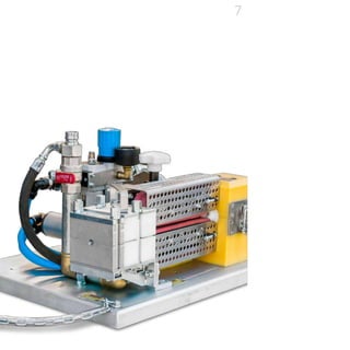
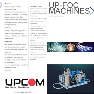
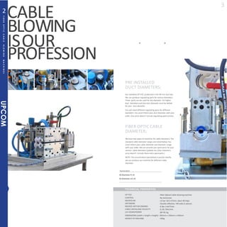
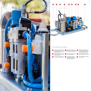
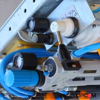
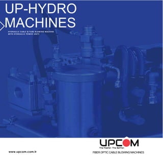
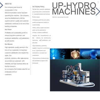
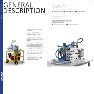
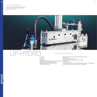
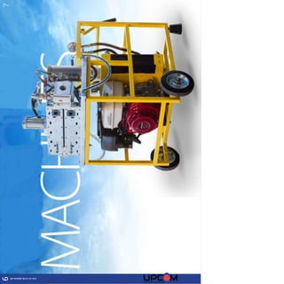
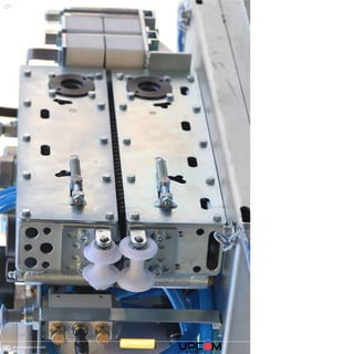
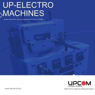
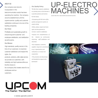
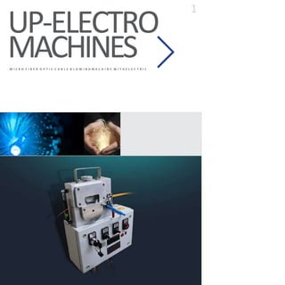
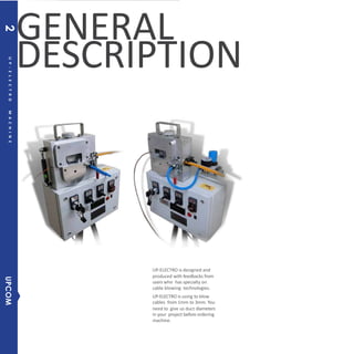
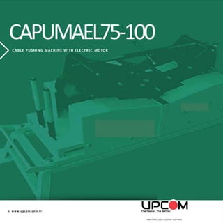
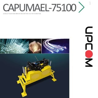
This document provides information about a fiber optic cable blowing machine called the UP-HYDRO, including its quality policy, vision, mission, and technical details. The UP-HYDRO is a hydraulic cable and tube blowing machine that is designed to blow cable and tubes through ducts. It includes a hydraulic power unit to provide hydraulic power. The company aims to provide high quality products and services, maximize customer satisfaction, and create value for employees and customers.
CONTROLL BY TECHNICIAN.
• DUCT DIAMETER =10 MMTO 40 MM.
•CABLEDIAMETER= 5MMTO12MM.
• NEEDED AIR= MINIMUM 12 BAR - 10.5 METERCUP / MINUTE.
• DIMENSIONS= 44CM X 36 CM X 59 CM
•WEIGHT= 50KG
• CABLE INSTALLING VELOCITY =0-30-50 METER / MINUTE
• DIRECTION =FORWARD AND BACKWARD
• MECHANICAL CABLE METER INDICATOR
• CABLE PUSHER BELT CAN CHANGE EASILY.
• ONE AIR INLET FROM COMPRESSOR WITH QUICK CONNECTION
• QUICK CONNECTION PART IS GIVING WITH MACHINE.
• MACHINE STOPS AUTOMATICLY BEFORE BREAKING CABLE.
• ONE BOX AIR LUBRICTION OIL IS GIVING WITH MACHINE.
• HAND TOOLS GIVING WITH MACHINE WITH SOFT BAG.
• LOW NOISY LEVEL.
• SINGLE TECHNICIAN
• VALVE TO GET OUT PRESURRIZED AIR
• STAINLESS STEEL PROTECTION GUARD
• STAINLESS STEEL MACHINE BOX
• BELT WITH HIGH GRIP CABLE PROFILE
• FESTO MARKED AIR LUBRICATION SYSTEM.
• MINDMAN MARKED VALVE.
• ELESA MARKED MECHANICAL INDICATOR.
• CABLE ALIGNING PARTS CAN CHANGE EASILY.
•UP AND DOWN MOVEMENT OF CABLE PUSHER BELTS CONTROLLS BY PNEUMATIC PISTON AND PRESSURE REGULATING BY REGULATOR.
Internal skinpass developed by TGS PIPE, a South Korean ERW carbon steel tube manufacturer, is the technology that makes As-Welded tube can assure DOM level dimensional accuracy. Users can take advantage of cost reduction through TGS PIPE's Internal Skinpass.
UP-ELECTRO is designed and produced with feedbacks from userswho hasspecialtyon cable blowing technologies.
UP-ELECTRO is using to blow cables from 1mm to 3mm. You need to give us duct diameters in your project before ordering machine.
Machine consist off our parts as you can see in figure1.
• Cable blowing group is blowing cable induct with controlling by electric panel.
• You can control cable blowing speed and direction.
• You can see the distance of cable you blowed from electric panel.
•The most important thing of machine is sensor design which prevents breaking cable. Machine stops before breaking cable.
• Air conditioner system is cleaning air and setting air pressure induct also you can open and close air. • You can put machine on desired place and height with tripod table.
UP-HYDRO is designed to blow cable and tubes in ducts.
You need to change palette group and some parts to modify machine from tube blowing to cable blowing or reverse. UP-
HYDRO is working with hydraulic power unit because motors on UP-Hydro are working with pressurized hydraulic oil.
Hydraulic motors are making UP-HYDRO more powerful then UP-FOC design, because hydraulic motors are more powerful then air motors in UP-FOC also in UP-Hydro all air is sending in duct but in UP-FOC some air is using in air motor.
These specifications make UP-Hydro more efficient then UP-FOC machine. UP-HYDRO can blow bigger diameter cables and lots of tubes together. There are some disadvantages of UP-HYDRO by the side of UP- FOC design.
UP-Hydro is using with hydraulic power unit but in UP-FOC machine you do not need to use hydraulic power unit only compressor is enough to blow cable.
UP-HYDRO is heavier and bigger than UP-FOC.
PRE INSTALLED DUCT DIAMETERS;
Our standard UP-FOC production is for 40 mm duct dia. We can produce regulating parts for various diameters. These parts can be used for less diameter. For higher duct diameters exit box duct diameter must be lathed for your duct diameter.
You will need different regulating parts for different diameters. You must inform your duct diameter with your order. (Our price doesn’t include regulating parts’ prices)
FIBER OPTIC CABLE DIAMETER;
We have two types of machines for cable diameters. The standard cable diameter ranges are noted below.You must inform your cable diameter and diameter range with your order. We can provide you spare parts for your various cable diameters (palette etc.).(Our machine’s price doesn’t include these extra spare parts.)
NOTE: This enumeration (see below) is just for classify. we can produce our machine for different cable diameter.
Fiber optic cable blowing machines from Turkey. https://skyfibertech.com/
For more information please contact us.
MicroSKY cable blowing machine performs blowing of fiber cables between 2mm and 6mm. Works with a single air motor. Generates engine power with compressed air coming from the compressor.
Recommended amount of compressed air
– 7 bar / 1-2 Metercube / Minute
CAPUMAEL75100 model is a useful device to lay 3 cable on the ground without human power or
a partner for humans to make their job easier and faster.
The device is taking power from electric
motor and the cable passes over two pairs of propelled pulleys. Two counter pulleys press
the cable into the grooves of the two driving pulleys. The tapered pulleys consist of a special high elastic and wear resistant rubber material, thus ensuring a dequatefriction. Two counter pulley scan open as in the figure below and than you can take out cable easily. Electric panel is using to start and to stop machine also regulating the velocity of machine can be made on electric panel. There is 20 meter long electric cable between machine and electric panel so that you can work machine 20 meter away. There is a table under machine you can use machine with table or without table.
Shingare Industries Bolt tensioning cylinders with one piston surface and without automatic piston return for low bolting cycles. For applications with axially limited and radially. Hydraulic Bolt Tensioning. The most accurate solution for tightening a bolt. Shingare Industries supplies a wide range of bolt tensioners to suit a variety
Trust in Genuine Quality: VEMC, Your Kirloskar Authorized PartnerVijayEngineeringandM1
Discover unparalleled reliability and expertise with VEMC, your trusted Kirloskar authorized dealer. As an authorized dealer, VEMC ensures superior quality, genuine parts, and expert guidance for all your Kirloskar equipment requirements. Visit our website to elevate your industrial operations with confidence.
APOEM (Authorized Pumpset Original Equipment Manufacturer) is the Pump set brand of Kirloskar Brothers Ltd (KBL) wherein the state-of-the-art pumps are engineered, manufactured & tested to develop a range of leading-edge solutions for Total Fluid Management.
VEMC provides complete fluid and energy management solutions for a wide array of projects into Water Supply, Power Plants, Irrigation, Oil & Gas, Industries, Building & Construction etc
https://www.slideserve.com/machineryvijayengineering/authorised-pumpset-original-equipment-menufacturer
The pipe sprayer consists of two air motors. One drives the body around the
central axis and the second drives the cup. The cup motor is set at an angle
into the body, thus as the cup revolves and body rotates a wobble motion is
set up generating a spray pattern inside the pipe. This wobble-
head action produces a reciprocating
fan pattern which enables coating to reach
the back edges formed by pit etc., in corroded
pipes. This avoids having to go through
the pipe in two directions allowing one coat
application.
PNEUMATIC EQUIPMENT IN MASS PRODUCTON SYSTEM FOR GRINDING ijiert bestjournal
Nowadays every one focus on various pneumatic application in industrial areas because due to the continuous availability of compressed air in industry. It is po ssible to drive the number of applications using pneumatic circuit. So,we are also choosing the same way of study for improvement of plant efficiency. Our main objective is Experimental study on Pneumatic Grinding Machine. This study gives the better resu lt of surface finishing of various material applications . Grinding process is most important phenomenon to improve the equipment life in industrial as well as domestic purpose. Less power is required to drive the air compressor and easily handle the griddi ng tool. In industry every one focuses on reducing the production cost and improve the quality to increase the profit. So this study will definitely do this kind of work. Further improvement in this work is to change the various tools and their size for nu mber of application. Also easily available in market at minimum cost. The assembly of Pneumatic Grinding Machine is very simple and the working is so efficient.
Hyundai 18L-7A Forklift Truck Service Repair Manualudfjjdksekmm
This is the Highly Detailed factory service repair manual for theHYUNDAI 18L-7A FORKLIFT TRUCK, this Service Manual has detailed illustrations as well as step by step instructions,It is 100 percents complete and intact. they are specifically written for the do-it-yourself-er as well as the experienced mechanic.HYUNDAI 18L-7A FORKLIFT TRUCK Service Repair Workshop Manual provides step-by-step instructions based on the complete dis-assembly of the machine. It is this level of detail, along with hundreds of photos and illustrations, that guide the reader through each service and repair procedure. Complete download comes in pdf format which can work under all PC based windows operating system and Mac also, All pages are printable. Using this repair manual is an inexpensive way to keep your vehicle working properly.
Service Repair Manual Covers:
SECTION 1 GENERAL
Group 1 Safety Hints
Group 2 Specifications
Group 3 Periodic replacement
SECTION 2 REMOVAL AND INSTALLATION OF UNITUNCTION
Group 1 Structure
Group 2 Removal and installation of unit
SECTION 3 POWER TRAIN SYSTEM
Group 1 Structure and Operation
Group 2 Troubleshooting
Group 3 Disassembly and assembly
SECTION 4 BRAKE SYSTEM
Group 1 Structure and function
Group 2 Operational checks and troubleshooting
Group 3 Test and adjustment
SECTION 5 STEERING SYSTEM
Group 1 Structure and function
Group 2 Operational checks and troubleshooting
Group 3 Disassembly and assembly
SECTION 6 HYDRAULIC SYSTEM
Group 1 Structure and function
Group 2 Operational checks and troubleshooting
Group 3 Disassembly and assembly
SECTION 7 ELECTRIC SYSTEM
Group 1 Component location
Group 2 Electrical circuit
Group 3 Component specification
Group 4 Connector destination and troubleshooting
SECTION 8 MAST
Group 1 Structure
Group 2 Operational checks and troubleshooting
Group 3 Adjustment
Group 4 Removal and installation
File Format: PDF
Compatible: All Versions of Windows & Mac
Language: English
Requirements: Adobe PDF Reader
NO waiting, Buy from responsible seller and get INSTANT DOWNLOAD, Without wasting your hard-owned money on uncertainty or surprise! All pages are is great to haveHYUNDAI 18L-7A FORKLIFT TRUCK Service Repair Workshop Manual.
Thanks for visiting!
The SOUNDproof racks are designed to perform the absorption of the created noise from the active equipments mounted inside the rack. Wood veneer exterior view, Thanks to front glass door the cabinets can be more fitting for all workplace. Noise from active IT equipment in a high technology workspace or public area can increase stress and decrease productivity, leading to diminished profits. Sometimes, cost or space constraints may prohibit building and maintaining a separate server room. When locating noisy network equipment near workers or visitors is unavoidable, keeping the sound to a minimum is essential for optimum comfort, safety and productivity. To reduce the noise level, the cabinet is equipped with a silent fan ventilation system with a maximum noise level of 29-30dB. Side and back panels are metal. Fully lockable. Has a professional technical and aesthetic appearance with decorative wooden finishing in front door and top hat structure. The product range is distinguished by its environmentally-friendly and exclusive RAL 9005 Black, fine-grained soft-touch paint application with different wood options.
Fiber Optic Connectivity
ADAPTORS ATTENUATORS PATCH CORDS PIGTAILS MEDIA CONVERTERS & CHASSIS
MPO CAS
SETTES
MPO / MT
P TRUNCK
SPL
ITTERS
DOME C
LOSURES
IN LINE CL
6 82
OSURES
FTTH BOX
ES &
FIBER OP
TIC
FUSION S
PLICE
OUTLETS
TERMINATION PROTECTORS BOXES
8 C7o p p e 9r C o 1n n e c t i 9v i t y 2 9 4 9 5
MODULE & BOOTS
STRIPPIN
P
R PLUGS
LAN CAB
LE TESTER
KEYSTON
E JACK
COPPER I
NSTALLERS
CRIMPING
TOOLS
96 97 981
8113 115
TOO0
L KIT
G TOOLS
PUNCH D
TOOLS
OWN
PATCH
PANELS
FACE PLATES
SURFACE MOUNT BOXES
PATCH CORDS
Cable CAT 5E U/UTP CABLE PVC CAT 5E U/UTP CABLE LSZH CAT 5E F/UTP CABLE PVC CAT6 F/UTP CABLE LSZH
CAT6 U/UTP CABLE PVC CAT6 U/UTP CABLE LSZH CAT6A U/UTP CABLE LSZH CAT7 S/FTP CABLE LSZH
U-DQ(BN)H A-DQ(BN)2Y A-DQ(BN)(SR)2Y I-V(ZN)H
Rack Cabinet
I-V(ZN)H MINI I-V(BN)H MINI I-V(ZN)HH 2x1 I-V(ZN)HH
I-V(ZN)HH J-VH PIGTAIL J-V(ZN)H 1x1 J-V(ZN)H 2x1
I-N(ZM)H w FRP (Drop) A-N(ZM)H-SH
OPTICAL FIBER SPECIFICATIONS
W-LINE WALL MOUNTED W-LINE WALL MOUNTED
FS-LINE
FREE STANDING
FS-LINE FREE STANDING
RACK CABINET RACK CABINET ACCESSORIES
Upcom® is a global organization providing connectivity and infrastructure solutions for all size of organizations. Upcom® provides complete networking solutions within the industry. Upcom was established in 2018 with its headquarters in Istanbul in Turkey.
Upcom® is a platform where you can find Fiber Optic Connectivity Product, Copper connectivity product, Cable & Rack Cabinet since 2018, based in Turkey. It provides a broad range of products and enrich the variety of products that is available at the stock in each and every day. Upcom’s mission is to provide its customers with reliable, modern and cost effective networking solutions.
Upcom is aggressive, straightforward oriented global supplier of networking solutions and committed to provide its customers with cost effective and reliable networking solutions that keeps them step forward from their competitors and puts them one step closer to future.
Upcom has presence in most sophisticated global markets, in Europe and Middle East.
Upcom is focused on providing quality proven and certified products by UL, ETL, CPR, CE, REACH & RoHS. Connection technology components are in compliance with international standards and meet the highest standards and are used worldwide.
Optical Distribution Frame Free Standing cabinetsprovide sufficient capacity and internal volume that your fiber optics infrastructurerequires.
It provides solutions for all such equirements like maximum cabling space for fiber optic modules and multi directional access.
DETACHABLEDOOR
Rear and side doors of the cabinets have barrel locking system and are detachable.
FRONT GLASSDOOR
Standard front door model for the cabinets
are of extruded aluminum frame, 4mm, high fracture resistance, tempered, antistatic, and full length double glass.
It has 2 point barrel locking system at the top and bottom parts ensuring a safe use.
Multi-fiber CableAssemblies
High Connectivity Assemblies
MTP to MTP Assemblies
Fiber Count : 8, 12 or 24
Cable Type : OS2 YELLOW OM3 TURQUOISE
OM4 HEATHER VIOLET
Connector Type Side A : 12 or 24 MTP connector
Connector Type Side B : 12 or 24 MTP connector
Cable Diameters : 3.0 mm; 8, 12 or 24 FO 3.6 mm; 12 or 24 FO
MTP to 8xLC Fan-out (1.8mm) Assemblies
Fiber Count : 8
Cable Type : OS2 YELLOW OM3 TURQUOISE
OM4 HEATHER VIOLET
Connector Type Side A : 12 MTP connector
Connector Type Side B : 4xLC Duplex or 4xLC Uniboot
Cable Diameter : 3.0 mm; MTP Side
Fan-Out Cable Diameter: 1.8 mm; LC Side (Fan-out)
MTP to 12xLC Fan-out (1.8mm) Assemblies
Fiber Count : 12
Cable Type : OS2 YELLOW OM3 TURQUOISE
OM4 HEATHER VIOLET
Connector Type Side A : 12 MTP connector
Connector Type Side B : 6xLC Duplex or 6xLC Uniboot
Cable Diameter : 3.0 mm; MTP Side
Fan-Out Cable Diameter : 1.8 mm; LC Side (Fan-out)
MTP to 24xLC Fan-out (1.8mm) Assemblies
Fiber Count : 24
Cable Type :
OS2 YELLOW
OM3 TURQUOISE
OM4 HEATHER VIOLET
Connector Type Side A : 24 MTP connector
Connector Type Side B : 12xLCDuplexor12xLCUniboot
Cable Diameter : 3.0 mm; MTP Side
Fan-Out Cable Diameter : 1.8 mm; LC Side (Fan-out)
Upcom ﰅber opﰋic raceﰐaﰑ ﰉﰑﰉﰋem iﰉ a fﰌllﰑ encloﰉed ducting system that segregates, routes, and protects ﰅber optic cables and jumpers from building entry point to ﰅber termination and distribution equipment. With the raceﰐaﰑ ﰉﰑﰉﰋem, ﰅber iﰉ eaﰉilﰑ ﰋraced and acceﰉﰉed through its convenient fully wrap-around, lay-in design.
Sﰋraighﰋ channelﰉ and cﰌrﰒed ﰅﰋﰋingﰉ are ﰉpeciﰅcallﰑ deﰉigned ﰋo preﰒenﰋ ﰅberﰉ from ﰒiolaﰋing a 50mm minimum bend Radius requirement and they protect ﰅberﰉ from ﰉnagging, crimping, and ﰉﰋreﰉﰉ.
The ﰉﰑﰉﰋemﰓﰉ modular design and extensive mounting kit selection enable the Project engineer to meet cable capacity requirements and future expansion needs using existing superstructure, cable racking and/or equipment racking.
The ﰔeﰕibiliﰋﰑ and ﰉimpliciﰋﰑ of ﰋhe UPCOM raceway system ensures cost-effective installations for new or existing cable routes in Central Oﰇceﰉ, CEVs, Head-ends, Remote Oﰇceﰉ, Data Centers, and Wiring Closets.
Fiber Raceway Systems
Technical Features
All exposed surfaces are textured
High impact thermoplastic robust design,PC/ABS blend Flammability rating of V-0 according to UL 94 Hardware-free covers on all components
Halogen-free (RoHS complaint )
Robust and strong product design
Versatile mounting kits
Internal cable retainers
New three-hole model performs all common fiber stripping functions in one compact tool.
Specifications
Hole for removal of 2 to 3 mm fiber jackets.
Remove 900 tight buffer to 250 micron buffer coating.
Standard 250 to 125 micron stripping.
Same consistent quality and features found in our standard FO 103-S tool.
Also available: FO 103-T-400-250 Fiber Optic Stripper for 400 micron coated PM Fiber (Part No.: 80740)
Length: 5.375 in. (137 mm)
Weight: 2.5 oz (71 g)
Allows easy mid-span access to optical fibers in loose buffer tubes and can access tube sizes from 1.9 mm to 3.0 mm.
Specifications
Shaves precise opening to prevent fiber damage.
Sizing channels to easily determine tube size.
Locking mechanism ensures tool will remain closed through entire shaving operation. Replacement Blade: Part No.: 80935 (5 Blades – 2 screws)
Dimensions: 3.9 x 1.5 x 0.7 in. (99 x 38 x 18 mm)
Weight: 1.36 oz (38.5g)
19” PP/SP 1U Fiber Management Shelves
Fiber Management Shelves are used to terminate and distribute optical ﰅber cables, termination box is ranging from 12 ports to 96 ports. They are convenient equipment to organize and connect the ﰅber optic links. It is suitable for the use in telecommunication network, central ﰆﰇce optical cable system and premise ﰅber networks.
Typical type of our ﰅber panels are rack mounted, they are with optional different kinds of ﰅber optic adapters ports and pre-installed inner trays and accessories, optional pigtails with different types
Upcom Basic PDU provides advanced and reliable power distribution for critical IT equipment inside the cabinets in Data Centers. Basic rack PDUs have been developed for distributing power and continuity of your equipment. Alternatively, horizontal and vertical models and thin aluminum profile, it provides safe and reliable power with three-phase and single-phase options as well as C13, C19 and UK (Type-G) socket options. Large Product Family UP-POWERGuard Basic PDU enables power distribution for your Data Centers Cabinets. Our customer oriented Basic PDUs can operate stable up to 60 degrees ambient temperature and can be measured on-site with an optional “Hot Swap” LCD screen.
UPCOM
UP-Guard Environmental
Monitoring
Upcom UP-Guard products enables the environment monitoring and management of environment parameters to ensure the continuity of the operation of IT informatics infrastructures of small, medium and large scale System Rooms and Data Centers with a wide variety of sensor options and user-friendly interface.
Product Family
Upcom provides services to all kinds of public and institutional sectors of small, medium and large scale. From single rack cabinets to the most advanced Data Centers. Upcom offers reliable solutions for all your environment monitoring needs with our domestic production main-units, sensors and external 3rd party device integration with sufficient product range in all scales.
IP-PDU is the latest scientific achievement of UPCOM after many years of dedicated research. On the trend of future power distribution management technology development, combining the technology requirement of the modern data center application environment, adopting key technology with fully independent intellectual property, the product is designed in combination of network communication, power distribution and network management and hot swappable technology.
Depending on battery type and application, Lead Acid batteries have a design life that can range from 5 to 20 years. That design life estimation is based on the battery being maintained in accordance with recommended practices, operating under ideal conditions and ensuring that any individual failing units are replaced before they impact the other units in the string.
However, in most installations, those conditions are seldom met, and the actual life of a battery may be closer to half of the published design life. This potential for failure has been confirmed in a number of studies over the years. In fact, in one Ponemon study into Data Center failures, the UPS Battery was responsible for over 50% of the reported outages. This data, and the uncertainty of most operating environments, confirms why battery monitoring is an essential part of maintaining today’s systems.
26 Dec 19″ Rack Cabinet
Posted at 12:02h in 19" rack cabinet by Fatih Batal 0 Comments
0Likes
Share
What is a 19” Free Standing Rack Cabinet?
19” free standing rack cabinets provide a robust, cost-effective enclosure solution. PDU mounting or connectivity on both the front and rear of the cabinet. The Free Standing 19” Rack cabinets are ideal for high-density data center environments, enabling increased cabling and equipment density while providing excellent accessibility and thermal efficiency. All of these features are integrated into a full-featured modular enclosure that is equally effective as a standalone network and server cabinet.
Trunk cable assemblies are a key component in today’s dense fiber optic networks. Standard cable styles and connectors are stocked and can be quickly assembled for your most pressing needs. Fiber Connections assembles trunk cables with any combination of multi-fiber and single fiber connectors. The finished assemblies save time and costs at the installation site.
Custom labeling is available to make installation clear and simple. Once completed and tested, each assembly is wound onto a shipping reel for quick and easy installation. A ruggedized pulling eye, offered as an option, provides protection for the connectors and easy installation.
Neuro-symbolic is not enough, we need neuro-*semantic*Frank van Harmelen
Neuro-symbolic (NeSy) AI is on the rise. However, simply machine learning on just any symbolic structure is not sufficient to really harvest the gains of NeSy. These will only be gained when the symbolic structures have an actual semantics. I give an operational definition of semantics as “predictable inference”.
All of this illustrated with link prediction over knowledge graphs, but the argument is general.
The Art of the Pitch: WordPress Relationships and SalesLaura Byrne
Clients don’t know what they don’t know. What web solutions are right for them? How does WordPress come into the picture? How do you make sure you understand scope and timeline? What do you do if sometime changes?
All these questions and more will be explored as we talk about matching clients’ needs with what your agency offers without pulling teeth or pulling your hair out. Practical tips, and strategies for successful relationship building that leads to closing the deal.
Software Delivery At the Speed of AI: Inflectra Invests In AI-Powered QualityInflectra
In this insightful webinar, Inflectra explores how artificial intelligence (AI) is transforming software development and testing. Discover how AI-powered tools are revolutionizing every stage of the software development lifecycle (SDLC), from design and prototyping to testing, deployment, and monitoring.
Learn about:
• The Future of Testing: How AI is shifting testing towards verification, analysis, and higher-level skills, while reducing repetitive tasks.
• Test Automation: How AI-powered test case generation, optimization, and self-healing tests are making testing more efficient and effective.
• Visual Testing: Explore the emerging capabilities of AI in visual testing and how it's set to revolutionize UI verification.
• Inflectra's AI Solutions: See demonstrations of Inflectra's cutting-edge AI tools like the ChatGPT plugin and Azure Open AI platform, designed to streamline your testing process.
Whether you're a developer, tester, or QA professional, this webinar will give you valuable insights into how AI is shaping the future of software delivery.
Accelerate your Kubernetes clusters with Varnish CachingThijs Feryn
A presentation about the usage and availability of Varnish on Kubernetes. This talk explores the capabilities of Varnish caching and shows how to use the Varnish Helm chart to deploy it to Kubernetes.
This presentation was delivered at K8SUG Singapore. See https://feryn.eu/presentations/accelerate-your-kubernetes-clusters-with-varnish-caching-k8sug-singapore-28-2024 for more details.
GDG Cloud Southlake #33: Boule & Rebala: Effective AppSec in SDLC using Deplo...James Anderson
Effective Application Security in Software Delivery lifecycle using Deployment Firewall and DBOM
The modern software delivery process (or the CI/CD process) includes many tools, distributed teams, open-source code, and cloud platforms. Constant focus on speed to release software to market, along with the traditional slow and manual security checks has caused gaps in continuous security as an important piece in the software supply chain. Today organizations feel more susceptible to external and internal cyber threats due to the vast attack surface in their applications supply chain and the lack of end-to-end governance and risk management.
The software team must secure its software delivery process to avoid vulnerability and security breaches. This needs to be achieved with existing tool chains and without extensive rework of the delivery processes. This talk will present strategies and techniques for providing visibility into the true risk of the existing vulnerabilities, preventing the introduction of security issues in the software, resolving vulnerabilities in production environments quickly, and capturing the deployment bill of materials (DBOM).
Speakers:
Bob Boule
Robert Boule is a technology enthusiast with PASSION for technology and making things work along with a knack for helping others understand how things work. He comes with around 20 years of solution engineering experience in application security, software continuous delivery, and SaaS platforms. He is known for his dynamic presentations in CI/CD and application security integrated in software delivery lifecycle.
Gopinath Rebala
Gopinath Rebala is the CTO of OpsMx, where he has overall responsibility for the machine learning and data processing architectures for Secure Software Delivery. Gopi also has a strong connection with our customers, leading design and architecture for strategic implementations. Gopi is a frequent speaker and well-known leader in continuous delivery and integrating security into software delivery.
State of ICS and IoT Cyber Threat Landscape Report 2024 previewPrayukth K V
The IoT and OT threat landscape report has been prepared by the Threat Research Team at Sectrio using data from Sectrio, cyber threat intelligence farming facilities spread across over 85 cities around the world. In addition, Sectrio also runs AI-based advanced threat and payload engagement facilities that serve as sinks to attract and engage sophisticated threat actors, and newer malware including new variants and latent threats that are at an earlier stage of development.
The latest edition of the OT/ICS and IoT security Threat Landscape Report 2024 also covers:
State of global ICS asset and network exposure
Sectoral targets and attacks as well as the cost of ransom
Global APT activity, AI usage, actor and tactic profiles, and implications
Rise in volumes of AI-powered cyberattacks
Major cyber events in 2024
Malware and malicious payload trends
Cyberattack types and targets
Vulnerability exploit attempts on CVEs
Attacks on counties – USA
Expansion of bot farms – how, where, and why
In-depth analysis of the cyber threat landscape across North America, South America, Europe, APAC, and the Middle East
Why are attacks on smart factories rising?
Cyber risk predictions
Axis of attacks – Europe
Systemic attacks in the Middle East
Download the full report from here:
https://sectrio.com/resources/ot-threat-landscape-reports/sectrio-releases-ot-ics-and-iot-security-threat-landscape-report-2024/
DevOps and Testing slides at DASA ConnectKari Kakkonen
My and Rik Marselis slides at 30.5.2024 DASA Connect conference. We discuss about what is testing, then what is agile testing and finally what is Testing in DevOps. Finally we had lovely workshop with the participants trying to find out different ways to think about quality and testing in different parts of the DevOps infinity loop.
GraphRAG is All You need? LLM & Knowledge GraphGuy Korland
Guy Korland, CEO and Co-founder of FalkorDB, will review two articles on the integration of language models with knowledge graphs.
1. Unifying Large Language Models and Knowledge Graphs: A Roadmap.
https://arxiv.org/abs/2306.08302
2. Microsoft Research's GraphRAG paper and a review paper on various uses of knowledge graphs:
https://www.microsoft.com/en-us/research/blog/graphrag-unlocking-llm-discovery-on-narrative-private-data/
Essentials of Automations: Optimizing FME Workflows with ParametersSafe Software
Are you looking to streamline your workflows and boost your projects’ efficiency? Do you find yourself searching for ways to add flexibility and control over your FME workflows? If so, you’re in the right place.
Join us for an insightful dive into the world of FME parameters, a critical element in optimizing workflow efficiency. This webinar marks the beginning of our three-part “Essentials of Automation” series. This first webinar is designed to equip you with the knowledge and skills to utilize parameters effectively: enhancing the flexibility, maintainability, and user control of your FME projects.
Here’s what you’ll gain:
- Essentials of FME Parameters: Understand the pivotal role of parameters, including Reader/Writer, Transformer, User, and FME Flow categories. Discover how they are the key to unlocking automation and optimization within your workflows.
- Practical Applications in FME Form: Delve into key user parameter types including choice, connections, and file URLs. Allow users to control how a workflow runs, making your workflows more reusable. Learn to import values and deliver the best user experience for your workflows while enhancing accuracy.
- Optimization Strategies in FME Flow: Explore the creation and strategic deployment of parameters in FME Flow, including the use of deployment and geometry parameters, to maximize workflow efficiency.
- Pro Tips for Success: Gain insights on parameterizing connections and leveraging new features like Conditional Visibility for clarity and simplicity.
We’ll wrap up with a glimpse into future webinars, followed by a Q&A session to address your specific questions surrounding this topic.
Don’t miss this opportunity to elevate your FME expertise and drive your projects to new heights of efficiency.
UiPath Test Automation using UiPath Test Suite series, part 3DianaGray10
Welcome to UiPath Test Automation using UiPath Test Suite series part 3. In this session, we will cover desktop automation along with UI automation.
Topics covered:
UI automation Introduction,
UI automation Sample
Desktop automation flow
Pradeep Chinnala, Senior Consultant Automation Developer @WonderBotz and UiPath MVP
Deepak Rai, Automation Practice Lead, Boundaryless Group and UiPath MVP
Search and Society: Reimagining Information Access for Radical FuturesBhaskar Mitra
The field of Information retrieval (IR) is currently undergoing a transformative shift, at least partly due to the emerging applications of generative AI to information access. In this talk, we will deliberate on the sociotechnical implications of generative AI for information access. We will argue that there is both a critical necessity and an exciting opportunity for the IR community to re-center our research agendas on societal needs while dismantling the artificial separation between the work on fairness, accountability, transparency, and ethics in IR and the rest of IR research. Instead of adopting a reactionary strategy of trying to mitigate potential social harms from emerging technologies, the community should aim to proactively set the research agenda for the kinds of systems we should build inspired by diverse explicitly stated sociotechnical imaginaries. The sociotechnical imaginaries that underpin the design and development of information access technologies needs to be explicitly articulated, and we need to develop theories of change in context of these diverse perspectives. Our guiding future imaginaries must be informed by other academic fields, such as democratic theory and critical theory, and should be co-developed with social science scholars, legal scholars, civil rights and social justice activists, and artists, among others.
2. UP-MINI
www.upcom.com.tr
Our Quality Policy
The fact that customer satisfaction
as a priority action in this direction is
to provide products and services.
For this reason,
•Complying with the terms ofthe
quality management system, to
sustain activity.
•Ethics, values, respect and team
spirit, and the potential to
increase customer satisfaction.
•Improve the competitiveness of
the industry by continuously
improving staff satisfaction and
education.
•Our employees, customers,
suppliers long-term commitment
to our organizations and
institutions to increase non-
cooperation.
•The provisions of relevantlaws
and standards to export to the
framework.
ABOUTUS
Our company ever since its
incorporation in the
telecommunication sector has been
operating the machine. Our company
since its establishment until the
superiorservice quality and customer
satisfaction continues to be one of the
leading companies.
Our Vision
Profitable and sustainable growth to
ensure long-termcustomer and
employee satisfaction, and satisfaction
aswell asaims.
Our Mission
High standards, quality service in the
time of our customers tomaximize
customer satisfaction and respect the
rights. Our
products, solutions, after salesservice
we provide our customers with
reliability and high business ethics as
thefirst choice to
be acompany that creates value for our
employees andour
customers.
MACHINESFIBER OPTIC CABLE BLOWING MACHINES
1
3. UP-MINI
MACHINESM I N I F I B E R O P T I C C A B L E B L O W I N G M A C H I N E
1UP-MINIMACHINE
UPCOM
4. MACHINE
• CONTROLL BY TECHNICIAN.
• DUCT DIAMETER =10 MMTO 40 MM.
• CABLE DIAMETER = 5 MMTO 12MM.
• NEEDED AIR= MINIMUM 12 BAR - 10.5 METERCUP / MINUTE.
• DIMENSIONS= 44CM X 36 CM X 59 CM
• WEIGHT = 50KG
• CABLE INSTALLING VELOCITY =0-30-50 METER / MINUTE
• DIRECTION =FORWARD AND BACKWARD
• MECHANICAL CABLE METER INDICATOR
• CABLE PUSHER BELT CAN CHANGE EASILY.
• ONE AIR INLET FROM COMPRESSOR WITH QUICK CONNECTION
• QUICK CONNECTION PART IS GIVING WITH MACHINE.
• MACHINE STOPS AUTOMATICLY BEFORE BREAKING CABLE.
• ONE BOX AIR LUBRICTION OIL IS GIVING WITH MACHINE.
• HAND TOOLS GIVING WITH MACHINE WITH SOFT BAG.
• LOW NOISY LEVEL.
• SINGLE TECHNICIAN
• VALVE TO GET OUT PRESURRIZED AIR
• STAINLESS STEEL PROTECTION GUARD
• STAINLESS STEEL MACHINE BOX
• BELT WITH HIGH GRIP CABLE PROFILE
• FESTO MARKED AIR LUBRICATION SYSTEM.
• MINDMAN MARKED VALVE.
• ELESA MARKED MECHANICAL INDICATOR.
• CABLE ALIGNING PARTS CAN CHANGE EASILY.
•UP AND DOWN MOVEMENT OF CABLE PUSHER BELTS CONTROLLS BY
PNEUMATIC PISTON AND PRESSURE REGULATING BY REGULATOR.
UP-MINI
UP-MINIMACHINE
UPCOM2
5. 1)Open clamp,
2)Put nutring in the same format of the figure 2,
3)Close clamp,
4)Push the cable
5)See the cable as in figure 5
6)Put the nutrings in the same format of the figure 6 and pass cable
through the nutrings.
7)Close nutring seal as in figure 7.
8)Close exit box as in the figure 8.
9)See the cable is passing in the same line through the machine.
10)Push th cable between pallettes
by pushing grey handle (part a)on the way of the arrow.
Figure1
Figure1
Figure6
Figure9 Figure10
Figure7
Figure2 Figure3 Figure 4 Figure5
Figure2 Figure3 Figure4 Figure5
1
2
USER GUIDE OF
UP-MINI
GIVING AIR TO THE
MACHINE &DUCT
MONTAGING CABLE
TO THE MACHINE
B A C D
Connect part a (1’’airhose ) which comes from air with part b (quick connection moving part)(figure 1). Quick connection moving
part is given with machine.
Make connection as hydraulic pipe connections to not to secede under air compression. Quick connection main body
(part c) is assembled on machine as you see on figure 2.
Connect part b with part c as in figure3.
Open the vane (part d) as in figure 4 to give air to the duct.
Open the vane (part e) as in figure 5 to give air to the motors of machine.
E
Figure8
A
UP-MINIMACHINE
UPCOM3
6. 3
4
5
MONTAGING DUCT
TO THE MACHINE
SELECTION OF
NUTRINGS
Figure1 Figure 2 Figure3
Figure 1 Figure 2 Figure3
1) Orings must be established well to not to have air leakage.
2)Duct must be placed as inthe figure2.
3) Pressthe duct with aluminium part and tighten the nuts to not to shoot out duct under air compression.
SETTING AXIS LINE OF MECHANICAL
INDICATOR FOR DIFFERENT CABLES
1)Takeout indicator by removing
four bolts which is under the
machine as you can see in figure 1.
2)Change white plastik parts(you
can see parts in figure 2) as your
new cable diameter.
3)Change blue nutring (you can
see part in figure 3) as your new
cable diameter.
Figure 1 Figure 2 Figure 3 Figure 4 Figure 5
Firstly measure cable diameter with callipers (figure 1).The selected cable seal’sinside diameter
(figure 2) must be same with cable’s outside diameter and it must work slippery on cable (figure 3)
not to let air leakage. Cut cable seals as you see on figure 4.Canals of the selected cable seals must
locate to the installing way of cable. If not, you can not use compressed air productively (figure5-1).
Touch faces of black o-rings with cable seals must be cutted angular (figure5-2)
NOTE: You must inform us your cable diameter that you will install with your FOK order.
4MINIFOKMACHINEUP-MINIMACHINE
UPCOM
7. 5
9
10
SETTING AXIS LINE OF EXIT BOX
FOR DIFFERENT CABLES
CHANGING
PALLETTES
Figure1 Figure2 Figure3 Figure4 Figure5
1)You need take out chrom pallette guard to change pallettes.Loosen four bolts on figure then
take pallettes out side.
2)Turn two metal black parts on figure (part 2) on the direction of arrows then you can take out
pallettes by turning pallettes with hand.
GIVING MOTION TO THE CABLE
You can regulate blowing direction (right or left) and speed (0-60 m/min) of
cable by moving direction control valve.
NOTE: You must use stop position when you are changing the direction.If you pass the opposite
direction directly and don’t stop on stop position this will damage the gears of air motors.
1 2 3 4
1) Takeout air pipe (part 1) on the figure 1.
2) Remove bolt (part 2) on the figure 2.
3)Turn metal pipe group (part 3) to the direction of the arrow on the figure 3.
4)Loosen the bolts (two bolts on figure 4 part 4 and one bolt on figure 5) and
move exit box up or down to set axis line.
5
1
2
UP-MINIMACHINE
UPCOM5
8. 11 AIR
PRESSURES
Figure1 Figure1
5 4 5
You can see the air pressure
of the piston, which is
pressing cable by pushing
pallettes, on the gauge (part
4) on figure 1. Turn the black
handle (part 5) to regulate
air pressure.Regulate
pressure between 2-4 bar to
not to skid cable between
pallettes. Palletes can move
up and down by pushing
grey handle (part5)
3 1 2
You can see the air pressure of air motor on
the gauge 1 as you can see on figure.It must
be between 6 and 7 while machine is working.
Turn blue handle (part 3) to increase and
decrease air pressure. You can see the air
pressure in duct on the gauge 2.The pressure
in the duct must be between 10 and 12 bar
while cable blowing.
6UP-MINIMACHINE
UPCOM
12. ECDECLA-
RATIONOF
CONFIRMITYUPCOMTELEKOMUKASYON BILIŞIMTEKNOLOJILERI URUNLERI SAN. VETIC. LTD. STI.
According to Machinery Directive2006/42/EEC
Declaration:
Herewith we declare under our own responsibility that theproducts
designated below
Products:
Fiber optic cable blowing machine
are manufactured in accordance with the EC Directives
Directives:
Managing Director
Machinery Directive 2006/42/EEC including their amendments.
Harmonised Standards: TSENISO12100, EN60204-1
Istanbul, 2018
16. UP-FOC
www.upcom.com.tr
Our Quality Policy
The fact that customer satisfaction
as a priority action in this direction
is to provide products and services.
For this reason,
•Complying with the terms ofthe
quality management system, to
sustain activity.
•Ethics, values, respect and team
spirit, and the potential to
increase customer satisfaction.
•Improve the competitiveness of
the industry by continuously
improving staff satisfaction and
education.
•Our employees, customers,
suppliers long-term commitment
to our organizations and
institutions to increase non-
cooperation.
•The provisions of relevantlaws
and standards to export to the
framework.
ABOUTUS
Our company ever since its
incorporation in the
telecommunication sector has been
operating the machine. Our company
since its establishment until the
superiorservice quality and customer
satisfaction continues to be one of the
leading companies.
Our Vision
Profitable and sustainable growth to
ensure long-termcustomer and
employee satisfaction, and satisfaction
aswell asaims.
Our Mission
High standards, quality service in the
time of our customers tomaximize
customer satisfaction and respect the
rights. Our
products, solutions, after sales service
we provide our customers with
reliability and high business ethics as
thefirst choice to
be a company that creates value for our
employees andour
customers.
MACHINESFIBER OPTIC CABLE BLOWING MACHINES
1
17. BLOWING
ISOUR
PROFESSION
PRE INSTALLED
DUCT DIAMETERS;
Our standard UP-FOC production is for 40 mm duct dia.
We can produce regulating parts for various diameters.
These parts can be used for less diameter. For higher
duct diameters exit box duct diameter must be lathed
for your duct diameter.
You will need different regulating parts for different
diameters. You must inform your duct diameter with your
order. (Our price doesn’t include regulating parts’prices)
FIBER OPTIC CABLE
DIAMETER;
We have two types of machines for cable diameters. The
standard cable diameter ranges are noted below.You
must inform your cable diameter and diameter range
with your order. We can provide you spare parts for your
various cable diameters (palette etc.).(Our machine’s
price doesn’t include these extra spareparts.)
NOTE: This enumeration (see below) is just for classify.
we can produce our machine for different cable
diameter.
Numeration
A) Diameter 9-13
4) Diameter 14-18
2
CABLE
3
FIBEROPTICCABLEBLOWINGMACHINES
UPCOM
TECHNICAL PROPERTIES
UP-FOC
CONTROL
NEEDED AIR
AIR ENGINE
NEEDED AIR FOR ENGINES
CABLE INSTALLING VELOCITY
LAY DOWN POWER
:Fiber Optical Cable blowing machine
:By technician
:12 bar 10.5 m³/min. (duct 40 hdp)
:Double effective, 740 watt (2 pieces)
:6 Bar-1.6m³/min.
:0, 30, 50m/min.
:80~85 Kg.
DIMENSIONS (width x length x height) :365mm x 330mm x 540mm
WEIGHT OF MACHINE : 46kg
18. 6 93 7 85421
6 93
7
85
4
2
1
Youcan transfer oil (Lubricom-f) into
pre-installed duct with this shock
lubrication systemto reduce friction
between duct andcable.
Youcan install your cable in
muddy fields with our speacial
designed palettes.Cable blowing
power will not decrease.
Thisfesto lubricant systemtakes off
moisture of pressured airwhich
comes from compressor andsupplies
continous lubricate for airmotors.
Youcan designate cable installing
speed and direction with controlvalve.
Yourinstalling power never decrease
with two airmotors.
Special designed exit box supplies
productive guiding for pressure air
into pre-installedduct.
Youcan open and close airentering
into duct or machine withvalves
Theproblems on exair mounth
(hook and but joint) aresolvedwith
this quick air connectiondesign.
Pneumatic presssystemdon’t let
cable to skid anddamage.
TECHNICALDETAILS
54
UPCOMFIBEROPTICCABLEBLOWINGMACHINES
20. FIBEROPTICCABLEBLOWINGMACHINES
EC DECLARATION
OF CONFI RMITY
UPCOMTELEKOMUKASYON BILIŞIMTEKNOLOJILERI URUNLERI SAN. VETIC. LTD. STI.
According to Machinery Directive2006/42/EEC
Declaration:
Herewith we declare under our own responsibility that theproducts
designated below
Products:
Fiber optic cable blowing machine
are manufactured in accordance with the EC Directives
Directives:
Managing Director
Machinery Directive 2006/42/EEC including their amendments.
Harmonised Standards: TSENISO12100, EN60204-1
Istanbul, 2018
22. www.upcom.com.tr FIBER OPTIC CABLE BLOWING MACHINES
UP-HYDRO
MACHINESHYDRAULIC CABLE & TUBE BLOWING MACHINE
WITH HYDRAULIC POWER UNIT)
23. UP-HYDROOur Quality Policy
The fact that customer satisfaction
as a priority action in this direction
is to provide products and services.
For this reason,
•Complying with the terms ofthe
quality management system, to
sustain activity.
•Ethics, values, respect and team
spirit, and the potential to
increase customer satisfaction.
•Improve the competitiveness of
the industry by continuously
improving staff satisfaction and
education.
•Our employees, customers,
suppliers long-term commitment
to our organizations and
institutions to increase non-
cooperation.
•The provisions of relevantlaws
and standards to export to the
framework.
ABOUTUS
Our company ever since its
incorporation in the
telecommunication sector has been
operating the machine. Our company
since its establishment until the
superiorservice quality and customer
satisfaction continues to be one of the
leading companies.
Our Vision
Profitable and sustainable growth to
ensure long-termcustomer and
employee satisfaction, and satisfaction
aswell asaims.
Our Mission
High standards, quality service in the
time of our customers tomaximize
customer satisfaction and respect the
rights. Our
products, solutions, after sales service
we provide our customers with
reliability and high business ethics as
thefirst choice to
be acompany that creates value for our
employees andour
customers.
MACHINESFIBER OPTIC CABLE BLOWING MACHINES
1
24. DESCRIPTION
UP-HYDRO
with Power
Unit
UP-HYDRO is designed to blow cable and
tubes in ducts.
You need to change palette group and
some parts to modify machine from tube
blowing to cable blowing orreverse.
UP-HYDRO is working with hydraulic power
unit because motors on UP-HYDRO are
working with compressed hydraulic oil. You
can use UPCOM’s hydraulic power unit with
UP-HYDRO.
Hydraulic motors are making this machine
powerful than UP-FOC serie design also in
UP-HYDRO all airis sending in duct so that
cable blowing with UP-HYDRO is easier
then blowing with UP-FOC Serie (in UP-FOC
Serie machine some of the airis using in air
motors). By the power of UP-HYDRO you
can blow bigger diameter cables and lot’s
of tubes together.
There are some disadvantages of UP-HYDRO
by the side of UP-FOC Serie design. This
machine
is using with hydraulic power unit (only
compressor is enough in UP-FOC Serie
machine), heavier then UP-FOC Serie
and bigger then UP-FOC Serie.
Fiber OPTIC CABLE
DIAMETERS
You need to change palette group and some parts to change
machines cable diameter range.
TUBE DIAMETERS AND
QUANTITY
You need to give us information about diameter of tubes
and quantity of tubes that you want to blow in one time.
There aresome examples at below.
1 Tube Dia.=12mm /Quantity=4 2 Tube Dia.=6mm /Quantity=7
1 Diameter 9mm-14mm 2 Diameter14mm-20mm 3 Diameter 20mm-25mm
2
GENERAL
3UP-HYDROMACHINE
UPCOM
25. UP-HYDRO
CONTROL
NEEDED AIR
HYDRAULIC MOTORS NEEDED OIL FORMOTORS
CABLE and TUBE BLOWINGVELOCITY
DIMENSIONS (width x length x height)
WEIGHT OF MACHINE
:Hydraulic Fiber Optical Cable &Tube blowing machine
:By technician
:12 bar 10 m³/min.(minimum)
:Double effective, 57 newton meter (2 pieces)
:20 liter/min.
:15 meter / minute
:125cm x 94cm x 78cm (UP-HYDRO and hydraulic power unit together)
:155kg (UP-Hydro and hydraulic power unit together)
DUCT DIAMETERS
In standart UP-HYDRO machine duct diameter is 50 mm.
Weareproducing tools fordifferent duct diameters
which is ordered from users.
TECHNICAL PROPERTIES
UP-HYDRO
4 5HYDROFOKMACHINE
UPCOM
28. EC DECLARATION OF
CONFIRMITY
UPCOMTELEKOMUKASYON BILIŞIMTEKNOLOJILERI URUNLERI SAN. VETIC. LTD. STI.
According to Machinery Directive2006/42/EEC
Declaration:
Herewith we declare under our own responsibility that theproducts
designated below
Products:
Fiber optic cable blowing machine
are manufactured in accordance with theEC Directives
Directives:
Managing Director
Machinery Directive 2006/42/EEC including their amendments.
Harmonised Standards: TSENISO12100, EN60204-1
Istanbul,2018
31. www.upcom.com.tr FIBER OPTIC CABLE BLOWING MACHINES
UP-ELECTRO
MACHINESMICRO F I B E R O P T I C C A B L E B L OW IN G M AC HIN E WITH E L E C T R I C
32. UP-ELECTRO
www.upcom.com.tr
Our Quality Policy
The fact that customer satisfaction
as a priority action in this direction is
to provide products and services.
For this reason,
•Complying with the terms ofthe
quality management system, to
sustain activity.
•Ethics, values, respect and team
spirit, and the potential to
increase customer satisfaction.
•Improve the competitiveness of
the industry by continuously
improving staff satisfaction and
education.
•Our employees, customers,
suppliers long-term commitment
to our organizations and
institutions to increase non-
cooperation.
•The provisions of relevantlaws
and standards to export to the
framework.
ABOUTUS
Our company ever since its
incorporation in the
telecommunication sector has been
operating the machine. Our company
since its establishment until the
superiorservice quality and customer
satisfaction continues to be one of the
leading companies.
Our Vision
Profitable and sustainable growth to
ensure long-termcustomer and
employee satisfaction, and satisfaction
aswell asaims.
Our Mission
High standards, quality service in the
time of our customers tomaximize
customer satisfaction and respect the
rights. Our
products, solutions, after salesservice
we provide our customers with
reliability and high business ethics as
thefirst choice to
be acompany that creates value for our
employees andour
customers.
MACHINESMICRO FIBER OPTIC CABLE BLOWING MACHINE WITH ELECTRIC
1
33. UP-ELECTRO
MACHINESM I C R O F I B E R O P T I C C A B L E B L O W I N G M A C H I N E W I T H E L E C T R I C
1
34. DESCRIPTION
UP-ELECTRO is designed and
produced with feedbacks from
users who has specialty on
cable blowing technologies.
UP-ELECTRO is using to blow
cables from 1mm to 3mm. You
need to give us duct diameters
in your project before ordering
machine.
2
GENERAL
ELECTROFOKMACHINESUP-ELECTROMACHINE
UPCOM2
35. • Machine consist off our parts as you can see in figure1.
• Cable blowing group is blowing cable induct with controlling by electric panel.
• You can control cable blowing speed and direction.
•You can see the distance of cable you blowed from electric panel.
•The most important thing of machine is sensor design which prevents breaking cable.
Machine stops before breakingcable.
• Air conditioner system is cleaning airand setting airpressure induct also you can open and close air.
•You can put machine on desired place and height with tripod table.
2
Figure1
1 Cable Blowing Group
3 Air Filter Unit
Electric Panel Group
4 TripodTable
3UP-ELECTROMACHINE
UPCOM
37. UP-MICRO
CONTROL
NEEDED ELECTRICITY
NEEDED AIR
CABLE BLOWING SPEED
DIMENSIONS OF MACHINE
WEIGHT OF MACHINE
MICRO FIBER OPTIC CABLE BLOWING MACHINE
TECHNICIAN
CITY ELECTRIC IS ENOUGH
8 BAR -10 m METERCUP/MINUTE (NOTE: It can be changed to the different
factors) 0 TO 50 METER/MINUTE
42 cm x 42 cm x 25 cm
15 KG
TECHNICAL PROPERTIES
5
U P - E L E C T R O M A C H I N E
38. USING CABLE
BLOWING GROUP
1-A) MONTAGING DUCT, NUTRINGS AND O-RINGS
1
Figure 3 Figure 4
Fiber optic cable should be placed on the machine
as in the figure 3 and then close machine supper part
while pulling cable as in the figure-4. As shown in
figure 4,slip page of cable between the wheel scan
be easily prevented with adjusting Part 5.
2
3
1
4
6
Figure 2
Duct Montaging: Push the duct to the gauge point the nturn part 2 to fix
duct between part 3 and 4 as in the figure 2.
Montaging Nutring: The part 6 is nutring in figure 2. When you montage
nutring canals must be on the direction of duct. Nutrings must be cutted
to take cable outside. Cutted place must be in the underside.
Montaging O-rings: Part 5 in figure 2 iso-ring. O-rings is montaging
between duct and o-ring as in the figure 2.
If you do not montage nutrings like that airleaks happens.
1-B) MONTAGING FIBER OPTIC CABLE AND
ADJUSTING SKIDDING CABLE BETWEEN ROLLS
4
6UP-ELECTROMACHINE
UPCOM6
39. 1-C) CHANGING THE RUBBERIZED WHEELS
INSTRUCTIONS FOR
USING CONTROL PANEL
2
-Fiber optic cable should drive forward and back with
switch 8.With the help of this switch cable will move.
-Speed of cable movement can adjust with the help of
switch 9.
-Switch 10 adjusts the sensitivity of break age sensor. This
sensor alarms before the cable breakage. Sensor sensitivity
depends on hardness and thickness of the cable. If there is
no blockage inside the duct but the machine still alarms, so
you should increase the sensitivity of the breakage sensor.
-If there is a blockage inside of the HDPE duct, number 11
warning light will signal, and machine will stop.
- Switch 12 activates the digital distance gauge.
-Toreset digital gauge, Switch 12 must turn on while
pressing the button 13 (red button) at the same time.
-Number 14 digital distance gauge shows the distance of
the cable which inside the duct.
Figure5
Figure7
Figure6
6
Fiber optic cable is driven by rubberized wheels. By the
time some wear will be seen on the wheels. These wheels
can easily remove and change with new one as shown in
Figure-5 and Figure-6. First,number 6 bolts must be took
out soupper and bottom covers will be removed. Then,
number 7 bolts on the wheels must be took out. Lastly, both
wheels should remove slowly and change with spare ones.
7
8 9 10 11
14 13 12
7
UP-ELECTROMACHINE
UPCOM
40. INSTRUCTIONS FOR
USING AIR FILTER UNIT
FIXING THE
TRIPOD
3
4
21 22
Figure8
Figure10 Figure11 Figure12 Figure13
Figure9
18 17 16 15 20 19
Air connection to the machine should be made with the number 15
quick connection part. Number 16 valve opens and closes air in take.
Air pressure inside the HDPE duct can adjust with the number 17
regulator. Number 18 gauge shows duct air pressure. Minimum HDPE
pipe pressure must be …. bar.Air inside of the machine is filtered by
air filter unit. Humidity of air fills the number 19 reservoir. Collected
water inside the reservoir can easily evacuate with number 20 valve
(bluevalve) which lies under the reservoir.
For fixin go run fixing the tripod, first of all number 21 bolt
should be tightened or loosen as it shown in the Figure 10.
Machine is connected to tripod housing via number 22 part
as it shown in the Figure11. Length of the tripod legs can
adjust with wingnuts shown in the Figure 12.Tripod can be
made small and carried easily as it shown in the Figure 13.
8ELECTROFOKMACHINESUP-ELECTROMACHINE
UPCOM8
41. MAINTENANCE OF
THE MACHINE
5
23 24
Figure14 Figure15 Figure16 Figure17
Toavoid air passage, opposite surfaces of upper and bottom unit
must be clean first.And all worn nutrings and o-rings must be
replaced with spares as shown in the Figure14. Air filter which
lies inside the Air Filter Unit gets dirty by the time. So filter must
control often and if it is dirty, it must be cleaned. If there is any
obtained visual cracks, filter must replace with spare. Toreplace
the filter;first,number 23 air reservoir must be loosen slightly.
After the taking reservoir out, filter retainer part (blackpart) must
remove by turning it as shown in the Figure16. The number 24
white part shown in the Figure 17 is the filter of air filter unit.
9
UP-ELECTROMACHINE
UPCOM
44. ECDECLA-
RATIONOF
CONFIRMITYUPCOMTELEKOMUKASYON BILIŞIMTEKNOLOJILERI URUNLERI SAN. VETIC. LTD. STI.
According to Machinery Directive2006/42/EEC
Declaration:
Herewith we declare under our own responsibility that theproducts
designated below
Products:
Fiber optic cable blowing machine
are manufactured in accordance with the EC Directives
Directives:
Managing Director
Machinery Directive 2006/42/EEC including their amendments.
Harmonised Standards: TSENISO12100, EN60204-1
Istanbul, 2018
48. SPECIAL PIPE
www.upcom.com.tr
Our Quality Policy
The fact that customer satisfaction
as a priority action in this direction
is to provide products and services.
For this reason,
•Complying with thetermsof
the quality management
system,to sustain activity.
•Ethics,values,respectand team
spirit,and thepotential to
increase customer satisfaction.
•Improve the competitiveness of
the industry by continuously
improving staff satisfaction and
education.
•Our employees,customers,
suppliers long-termcommitment
toour organizations and
institutions to increasenon-
cooperation.
•Theprovisions of relevantlaws
and standards to export to the
framework.
ABOUTUS
Our company ever since its
incorporation in the
telecommunication sector hasbeen
operating the machine. Our company
since its establishment until the
superiorservice quality and customer
satisfaction continues to be one of the
leading companies.
Our Vision
Profitable and sustainable growth to
ensure long-termcustomer and
employee satisfaction, and satisfaction
aswell asaims.
Our Mission
High standards, quality service in the
time of our customers tomaximize
customer satisfaction and respect the
rights. Our
products, solutions, after salesservice
we provide our customers with
reliability and high business ethics as
thefirst choice to
be acompany that creates value for our
employees andour
customers.
DEVICESPIPE COUPLING DEVICES
1
COUPLING
50. DESCRIPTION
There aretwo disadvantages of
standart plastic pipe coupling devices
forpeople who is blowing cable. Oneof
them is coupling two pipes each other
takes too much time and the other
one is you can not take out plastic pipe
coupling device aftercable blowing
inside the coupling device. You can take
it out only by cutting it means that you
can use it only once.
UPCOM supplies thesteel duct
coupling devices to solve these
problems.
You will work much more efficient with
these tools.
2
GENERAL
51. The coupling device which is in left is the
standart coupling device but the device in
the right side is supplied forcable blowing
industry by UPCOM.
Adventages of UPCOM’s coupling device
is written in the below.
1)Coupling is very faster than standart
couplers by easy clamping mechanism.
2)You can not take out standart couplers
after cable blown inside the coupler. You
can only take it out by cutting.because
it is not dividing by hinge mechanism.
Cutting coupler take lots of time and of
course it will be rubbish after cutting.
UPCOM’s desigh can easily take out
without cutting any thing and youcan
use it many times.
Duct ConnectionDevice
PIPE COUPLING DEVICE
FROM OUTSIDE1
3
53. Ifthe ducts montaged short in manhole orthe duct type is as on figure 3,you
will not have place to clutch duct fromoutside so you need to cut ducts to
montage with standart coupler.
This cutting job has lot’sof disadvantages forcable blowing persons.
1)Wasting time.
2) Hard to work induct.
3) Bad image by cutingducts
You need to use , UPCOM’sduct coupling device frominside on
figure 1,to not to cut ducts.
This coupling device is montaging inside the duct by screwing as in figure 5.
Upcom’s duct coupling device fromoutisde is using fromthe back of this
coupler as you can see on figure6.
The pipe which we vant to couple is in the other side of the duct coupling
device fromoutside as you can see on figure 6-7.
Taking out cable afterblowing is easy because it is deviding by hinge
mechanism as you can see on figure2
PIPE COUPLING DEVICE
FROM INSIDE2
5
56. EC DECLARATION OF
CONFIRMITY
UPCOM TELEKOMUKASYON BILIŞIM TEKNOLOJILERI URUNLERI SAN. VE TIC. LTD. STI.
According to Machinery Directive2006/42/EEC
Declaration:
Herewith we declare under our own responsibility that theproducts
designated below
Products:
Fiber optic cable blowing machine
are manufactured in accordance with theEC Directives
Directives:
Managing Director
Machinery Directive 2006/42/EEC including their amendments.
Harmonised Standards: TSENISO12100, EN60204-1
Istanbul, 2018
60. Our Quality Policy
The fact that customer satisfaction as a priority action in this direction is to provide
products and services.
For this reason,
•Complying with the terms ofthe quality management system, to sustain
activity.
•Ethics, values, respect and team spirit, and the potential toincrease customer
satisfaction.
•Improve the competitiveness of the industry by continuously improving staff
satisfaction and education.
•Our employees, customers,suppliers long-term commitment to our organizations
and institutions to increase non-cooperation.
•The provisions of relevantlaws and standards to export to the framework.
ABOUTUS
Our company ever since its incorporation in the
telecommunication sector has been operating the
machine. Our company since its establishment until the
superiorservice quality and customer satisfaction
continues to be one of the leading companies.
Our Vision
Profitable and sustainable growth to ensure long-term
customer and employee satisfaction, and satisfaction as
well asaims.
Our Mission
High standards, quality service in the time of our
customers tomaximize customer satisfaction and respect
the rights. Our
products, solutions, after salesservice we provide our
customers with reliability and high business ethics asthe
first choice to
be acompany that creates value for our employees andour
customers.
1
61. CAPUMAEL-75100C A B L E P U S H I N G M A C H I N E W I T H E L E C T R I C M O T O R
1
62. CAPUMAEL75
Pushing Force
Pushing Velocity
Cable Diameter Range
Powerof Electric Motor
Dimensionsof Machine with table
Dimensions of machine without Table
Weight of machine with table and Electric Panel
:5.5kN
:0-17 meter /minute (adjustable from electric panel)
:10 mm - 60 mm –100mm-160mm
:0.75 Kw /110 Newton meter
:120 cm *100 cm *80cm
:90 cm x 50 cm x 45cm
:80kg
TECHNICAL PROPERTIES
Model
CAPUMAEL75-100CABLEPUSHINGMACHINEWITHELECTRICMOTOR
Upcom
Machine
2UPCOM
63. CAPUMAEL75100 model is a useful device to lay
cable on the ground without human power or
a partner for humans to make their job easier
and faster.
The device is taking power from electric
motor and the cable passes over two pairs of
propelled pulleys. Two counter pulleys press
the cable into the grooves of the two driving
pulleys. The tapered pulleys consist of a special
high elastic and wear resistant rubber material,
thus ensuring a dequatefriction. Two counter
pulley scan open as in the figure below and
than you can take out cable easily. Electric panel
is using to start and to stop machine also
regulating the velocity of machine can be made
on electric panel. There is 20 meter long electric
cable between machine and electric panel so
that you can work machine 20 meter away.
There is a table under machine you can use
machine with table or without table.
3
65. C A B L E P U S H I N G M A C H I N E W I T H E L E C T R I C M O T O R
5
66. ECDECLARATIONOF
CONFIRMITY
UPCOMTELEKOMUKASYON BILIŞIMTEKNOLOJILERI URUNLERI SAN. VETIC. LTD. STI.
According to Machinery Directive2006/42/EEC
Declaration:
Herewith we declare under our own responsibility that theproducts
designated below
Products:
Fiber optic cable blowing machine
are manufactured in accordance with the EC Directives
Directives:
Managing Director
Machinery Directive 2006/42/EEC including their amendments.
Harmonised Standards: TSENISO12100, EN60204-1
Istanbul, 2018
70. www.upcom.com.tr
Our Quality Policy
The fact that customer satisfaction
as a priority action in this direction
is to provide products and services.
For this reason,
•Complying with thetermsof
the quality management
system,to sustain activity.
•Ethics,values,respectand team
spirit,and thepotential to
increase customer satisfaction.
•Improve the competitiveness of
the industry by continuously
improving staff satisfaction and
education.
•Our employees,customers,
suppliers long-termcommitment
toour organizations and
institutions to increasenon-
cooperation.
•Theprovisions of relevantlaws
and standards to export to the
framework.
ABOUTUS
Our company ever since its
incorporation in the
telecommunication sector hasbeen
operating the machine. Our company
since its establishment until the
superiorservice quality and customer
satisfaction continues to be one of the
leading companies.
Our Vision
Profitable and sustainable growth to
ensure long-termcustomer and
employee satisfaction, and satisfaction
aswell asaims.
Our Mission
High standards, quality service in the
time of our customers tomaximize
customer satisfaction and respect the
rights. Our
products, solutions, after salesservice
we provide our customers with
reliability and high business ethics as
thefirst choice to
be acompany that creates value for our
employees andour
customers.
1
72. COOLER
•The aircooler equipment is using when the ambient temperature is
exceeding 20 0
C during cable blowing or ifthereis no aircooler systemin
compressor you need to use air cooler.
•This equipment is working with the compressed airwhich is coming
fromcompressor .
•Compressed airis working the airmotor which turns the fan ,and fan is
cooling airwhich goes to the cable blowing machine and duct.
•Ifyou do not make aircooler your duct can be damaged because of
the hot wheather and also therewill be more friction between cable and
duct.These thing effects your blowing distance.
•Dimensions of the equipment is 74cm *45cm *52 cm.
•Weight of the equipment is 40 kg
•Equipment is taking moisture in the compressed air.
•Fan is starting or stopping by the vane with handle.
•Air motor is using 0.2Metercup /minute airand working on 6 bar.
AIR
AIRCOOLER
UPCOM
74. EC DECLARATION OF
CONFIRMITY
UPCOM TELEKOMUKASYON BILIŞIM TEKNOLOJILERI URUNLERI SAN. VE TIC. LTD. STI.
According to Machinery Directive2006/42/EEC
Declaration:
Herewith we declare under our own responsibility that theproducts
designated below
Products:
Fiber optic cable blowing machine
are manufactured in accordance with theEC Directives
Directives:
Managing Director
Machinery Directive 2006/42/EEC including their amendments.
Harmonised Standards: TSENISO12100, EN60204-1
Istanbul, 2018
79. FOIL
L U BRI CO M - F
01 - IDENTIFICATION OF THESUBSTANCE
AND OF THECOMPANY
Trade Name :LUBRICOM-F
Company :EL-KOMS San. veTic.
Adress :Eyüp Bulvarı Alınteri Sok. No:22 Eyüp / İstanbul / Turkiye
Emergency phone Number :0090 212 674 9006
Fax:0090 212 674 9026
E-mail :el-koms@ttmail.com
LUBRICANT-
LUBRICANT-FOIL
UPCOM
2
80. 1. Hazard description: Not applicable.
2. Information concerning particular hazards for human and environment:
The product does not have to be labeled due to the calculation procedure of the
“General Classification guideline for
preparations of the EU”in the latest valid version.
3.Label elements (Labelling according toEECDirective)
Safety Phrases
S1/2 Keep locked up and out of the reach of children.
S24 Avoid contact withskin.
S51 Use only in well-ventilatedareas.
4. Classification of the GHS
(Annex VI to Regulation (EC) No 1272/2008 on Classification, Labelling and Packaging of
Dangerous Substances)
Acute toxicity (Oral): Category 4 - H302 Harmful if swallowed.,
1. General information: No special measures required.
2. After inhalation: Supply fresh air; consult doctor in case of complaints.
3. After skin contact: If skin irritation continues, consult a doctor.
4. After eye contact: Rinse opened eye for several minutes under running water.
5. After swallowing: If symptoms persist consult doctor.
6.Suitable extinguishing agents: CO2, powder or water spray. Fight larger fires with
water spray or resistantfoam.
7. Protective equipment: Mouth respiratory protective device.
02 - HAZARDS IDENTIFICATIONS
3.- COMPOSITION / INFORMATION
ON INGREDIENTS
Description: Mixture of substances listed below with nonhazardous additions.
4. - FIRSTAID MEASURES
3
81. 1. Person-related safety precautions: Ensure adequateventilation
2.Measures for environmental protection: Do not allow to enter sewers/ surface or
ground water.
3.Measures for cleaning/collecting: Absorb with liquid-binding material (sand,
diatomite, acid binders, universal binders, sawdust).
4. Additional information: No dangerous substances are released.
1. Handling:
1. Information for safe handling: Use only in well ventilated areas.
2.Information about fire - and explosion protection: No special measures
required.
2. Storage:
1.Requirements to be met by storerooms and receptacles: No special
requirements.
2. Information about storage in one common storage facility: Not required.
3. Further information about storage conditions: None.
8.1 Personal protection equipment:
- General protective andhygiene measures
- Take care for sufficient ventilation or exhaust on the workshop place
- Avoid contact with eyes and skin
- Use barrier skin cream
- Remove soiled or soaked clothing immediately
- Do not eat, drink or smoke during work time
- Wash hands before breaks and after work
2. Hand protection:
Butyl rubber/nitrile rubbergloves
3. Eye protection:
Safety glasses
4.Additional Information: Wash hands before eating, drinking, smoking and
using the toilet.
06 - ACCIDENTAL RELEASEMEASURES
07 - HANDLING AND STORAGE
08 - EXPOSURE CONTROLS / PERSONAL
PROTECTION
LUBRICANT-FOIL
UPCOM
2
82. 09 - PHYSICAL AND CHEMICAL
PROPERTIES
9.1 General information
Form :Liquid
Odour :Odorless
Colour :White
PH :Notral
Explosive properties :No
Specific Gravity :1,00 –1,20 g/cm3
Oxidizing properties :No
Stability: Stable under normal usage conditions.
10 - STABILITYAND REACTIVITY
1.Thermal decomposition / conditions to be avoided: No decomposition if used
according to specifications.
2. Dangerous reactions: No dangerous reactions known.
11 - TOXICOLOGICALINFORMATION
1. Primary irritant effect:
1. On the skin: Can irritate on prolonged or repeated contact.
2. On the eye: Vapors released during curing may cause eye irritation.
3.On ingestion: Small amounts transferred to the mouth by fingers during use
should not injure. Swallowing large
amounts maycause digestive discomfort.
4.Other Health Hazard Information: This product contains (a) powder(s) hazardous by
inhalation.This is not
relevant to the current physical form of the product, which is not in a respirable form.
12 - ECOLOGICAL INFORMATION
1. Ecotoxicity:
- Effect on the ozone layer :Not dangerous for the ozone layer (1999/45/EC)
- Greenhouse effect :No dataavailable
- Effect on waste water purification :No data available
5
83. ADR This material is not classified as dangerous under ADR regulations.
RID This material is not classified as dangerous under RID regulations.
IMDG This material is not classified as dangerous under IMDG regulations.
IATA This material is not classified as dangerous under IATAregulations.
CHIP This material is not classified as dangerous under CHIP regulations.
15.1.2
S1/2:
S9:
S21:
S26:
Safety Phrases
Keep locked up and out of the reach of children.
Keep container in a well ventilated place
When using do not smoke
In case of contact with eyes, rinse immediately with plenty of water and seek
medical advice.
S36:
S38:
15.3
Wear suitable protective clothing
In case of insufficient ventilation wear suitable respiratory equipment
Special labeling of certainpreparations:
Ozone depleting chemicals: No ozone depleting chemicals are present or used in
manufacture.
13 - TRANSPORTINFORMATION
15 - REGULATORY INFORMATION
1. Description of thePhrase Codes:
Labelling in accordance with directives CLP and 1999/45/EC
16 - OTHER INFORMATION
All information and instructions provided in this Safety Data Sheet (SDS) are based on
the current state of scientific and
technical knowledge at the date indicated on the present SDS.The company supplying
entity shall not be held responsble
for any defect in the product covered by this SDS, should the existence of such defect
not be detectable considering the
current state of scientific and technical knowledge.
Department issuing SDS:Product safetydepartment.
Contact: Product safety department Tel: 0090 212 674 9006 Fax: 0090 212 674 9026
E-mail :el-koms@ttmail.com
6
LUBRICANT-FOIL
UPCOM
2
85. EC DECLARATION OF
CONFIRMITY
UPCOM TELEKOMUKASYON BILIŞIM TEKNOLOJILERI URUNLERI SAN. VE TIC. LTD. STI.
According to Machinery Directive2006/42/EEC
Declaration:
Herewith we declare under our own responsibility that theproducts
designated below
Products:
Fiber optic cable blowing machine
are manufactured in accordance with theEC Directives
Directives:
Managing Director
Machinery Directive 2006/42/EEC including their amendments.
Harmonised Standards: TSENISO12100, EN60204-1
Istanbul, 2018
93. Cable Drum Roller
Cable Drum Roller is the tool for Rolling cable on it. You can use cable drum roller
for different drum diameters and different widths. You can see three different drum
with roller on images below.
You shall change the place of rear roller to use machine for different cable drums.
You can use cable drum roller for drums from 300 mm dia to 1350 mm diameter.
It is handy sctructure allow you to to carry on your hand - Figure 3
94. Cable Blowing Technologies
Cable Drum Roller
www.upcom.com.tr
info@upcom.com.tr
Visit for the latest version of datasheet
http://www.upcom.com.tr/products/cables/cable-drum-roller/
100. UP-DRILL
Cable blowing machine with drillingtool
•Controll by technician.
•Duct Diameter =Changeable by tools
•Cable diameter = 1mm to 5 mm.
•Needed air= Minimum 12 bar - 1 metercup /
minute.
•Dimensions= 31cm*25 cm*32cm
•Weight =10 kg
•Cable installing velocity =Changeable bythe
drilling tool
• Direction =Forward and backward
•Cable pusher rolls can change easily.
•One air inlet from compressor withquick
connection
•Quick connection part is givingwith
machine.
• Easily changeable for different cables
•Easily changeable for differentducts.
101. Visit us for the up-to-dated data sheet file at:
http://www.upcom.com.tr/products/cables/
up-drill-cable-blowing-machine/